Version 14 COURSE UNIT 6. Visualisation
|
|
|
- Ursula Osborne
- 5 years ago
- Views:
Transcription

1 Version 14 COURSE UNIT 6 Visualisation
2 Table of Contents Introduction... 2 Preparation... 3 Materialization... 4 View position... 9 Camera Create design model view Move background image Repetition Light sources Render Edit material Area render Radiosity Radiosity Update With render image Define cut out Define plot Modify section (plot) Calculate final images Save image Print

3 INTRODUCTION How to use this course unit This course unit is not a manual but a combination of theory and workshops with which to learn the programme on a 1-to-1 basis. Every mouse-click and every entry is described in detail, providing you with a teaching resource that lets you learn the basics of the programme by yourself. Each chapter provides explanations, information, and a workshop to practise the functions. To enable the workshops to be completed smoothly, the explanations should be read through very carefully. The order of chapters should not be changed because each workshop builds on the previous one. The programme DVD contains examples stored as an ELITECAD file, enabling problematic places to be reviewed. Conventions used in this course unit The start and end of a workshop are marked as follows: WORKSHOP WORKSHOP END Functions are written in block capitals. The corresponding icon also appears for new functions. FUNCTIONS (BLOCK CAPITALS) Functions can be accessed directly using icons (buttons). The functions are grouped together in toolbars or in the large tool management. [Enter] Function keys on the keyboard appear within square brackets. Input values (bold) Input values must be entered using the keyboard. When the text is entered in the input line, it must be confirmed with the [Enter] key. 2


4 PREPARATION WORKSHOP In this course unit we start with the project CAD_Object6. First, load the project. 1. Open project Select the project "CAD_Object6" and confirm with OK. 2. Menu FILE > OPEN Select the model "Starting Position" and open it. The opened model should look as follows. WORKSHOP END 3


5 MATERIALIZATION State materials for objects A function for materials allocation is offered in the respective parameter screens. Users can toggle between material mode and colour mode. Material mode Colour mode Allocating materials using "drag and drop" The other option for allocating materials is using "drag and drop". The material can be dragged and dropped from the Materials editor onto the component in question. TIP If you want to allocate the same material to multiple surfaces or objects, etc., there is a multiple allocation function. Drag the material onto a surface as normal. However, instead of releasing it, press the [Shift] key on the keyboard or the "+" sign. Click and hold down the mouse and move it to a different surface before pressing one of the two buttons. This can be repeated any number of times. 4

![.. or use the key combination [Ctrl]+[7]. 2.](/docs-images/90/102040476/images/6-1.jpg "Switch the allocation mode to \"Replace\". 3.")

6 WORKSHOP 1. Open the Materials editor. Menu View > Window > Material... or use the key combination [Ctrl]+[7]. 2. Switch the allocation mode to "Replace". 3. In the Materials editor, double-click to switch to the folder "Boards". 4. Drag and drop the material "Planks001" onto the fence. 5


7 5. In the materials editor, switch to the folder above. 6. Double-click on the folder "Timber", drag and drop the material "Maple001" onto the fence. 7. In the Materials editor, switch to the main folders. 8. Double-click on the folder "Surroundings/Grounds/Lawn+Grass", drag the material "Lawn002" and drop it onto the lawn. 6


8 9. In the materials editor, switch to the folder above. 10. Double-click on the folder "Surroundings/Grounds/Nutrient Media", drag the material "Loam001" and drop it onto the ground. 11. In the materials editor, switch to the folder above. 12. Double-click in the folder "Surroundings/Grounds/Board lining", and drag and drop the material "Gardendish011" onto the seat. 7
9 13. Now add the remaining materials. Garage door: Wood/Cladding/Sheeting004 Street: Surroundings/Grounds/Hard planes/asphalt002 Forecourt and sidewalk: Surroundings/Grounds/Hard planes/asphalt005 Kerb: Surroundings/Grounds/Hard planes/asphalt001 Retaining wall for street: Stone/Concrete/Coarse concrete/course concrete003 Retaining wall house: Stone/Concrete/Exposed concrete/exposed concrete004 Exterior staircase: Stone/Concrete/Exposed concrete/exposed concrete002 Roof: Stone/Tile/Rooftiles/Tile101 Masonry: Finery/Finery/Finery001 Tinwork: Metal/Metals/Copper Banister: Metal/Metals/Chrome Window glass: Glass/Glasses/Pane glass The model should now look roughly as follows. WORKSHOP END TIP Materials that were accidentally allocated can be deleted by clicking "Material for delete". Depending on the "allocation mode", the material is deleted on the relevant planes. 8


10 VIEW POSITION This function is used to observe the 3D object from any point and in any direction. You can finely tune the direction of view using the camera screen below. The design model depiction is automatically set to be in perspective. WORKSHOP 1. Activate "Without structure". Important: In the ARS version of ELITECAD, you cannot perform any action in Storeys Manager because the model has more than one structure. It does not matter that another storey may be currently active. You can specify the height of the camera in the camera window as you prefer. 2. Image start point 3. Select the function View position. Please click View position or ENTER 4. Using the capture mode Freehand select the point P1. Please enter height of view position 5. Enter the value 300 into the input line and confirm the value [Enter]. Please click point of vision 6. Using Capture Freehand mode, select point P2. Please enter height for point of vision 7. Enter the value 300 into the input line and confirm the value [Enter]. P P WORKSHOP END 9

11 CAMERA The camera is set in the 4-views window. If the camera screen is open, only the camera symbol can be clicked in CAD. Selecting or manipulating CAD objects is not possible. The depiction of the design model view can be controlled separately. If you right-click in this area, a menu opens where you can select how the design model view should be depicted. This is also true for the other views, as they are interconnected. Front Side Floor Design Using the camera in the 4-view window Various handles are available, which you can use to manipulate the camera interactively while left-clicking. Modify position of camera Move camera Modify direction of camera Modify opening angle of camera 10


12 WORKSHOP 1. Set the opening angle in the camera screen to Correct the angle of view so that the model is located roughly in the middle of the model window. 3. Confirm the camera screen with OK. WORKSHOP END 11


13 CREATE DESIGN MODEL VIEW. This function stores the 3D view angle currently set on your model as model view. In case you wish to change the view angle of a view model, right-click in the view and select "Modify cut-out" from the context menu. You are now "within" the limitation framework and can move around using the centre mouse button and the zoom functions, as usual. The size of the section can also be changed using the handles. The camera position and the section are saved by pressing [Esc] or CANCEL. WORKSHOP 1. Create new design model view. 2. Enter the name, set the display to solid, switch the background on and switch to material mode. 3. In the material mode, click on the selection button and then on Surroundings. 12


14 4. Now switch to the folders Background/Land/ and select the material Land Next, confirm the screen with OK. 6. Load the model view onto the screen. 7. Save work copy [Ctrl]+[W] WORKSHOP END 13

15 MOVE BACKGROUND IMAGE Depending on the camera setting and angle, moving or scaling the background image is required so that it fits correctly. To do so, right-click to open the context menu. Here you will see two menu items for Moving and Scaling. If you also press [Ctrl] when scaling, the image can be modified not to scale. WORKSHOP 1. Right-click in the model window and select Move background image. Please indicate reference point 2. Now left-click in the image. Please enter NEW position for alignment point 3. Set down the background image roughly as shown below. 4. The function remains active so that the action can be repeated until the image is correct. Afterwards, cancel the function with [Esc]. WORKSHOP END 14


16 REPETITION Now try to define another model view in the interior. WORKSHOP 1. Return to the model view and define another viewpoint in the living area. 2. Save this camera as new model view as well. Enter the name Interior view and use the same options as described above. Load the view onto the screen and move the background image, too. 15
17 3. Allocate materials to the interior view. Slab: Wood/Parquet/Parquet block/oak006 Stairs: Wood/Parquet/Parquet block/oak006 Truss: Wood/Timber/Ash001 Roofing: Wood/Cladding/Sheeting022 Oven: Metal/Metals/Alu Banister: Metal/Metals/Chrome Kitchen worktop: Stone/Quarry stone/marble/marble002 Slab faces for stair exit: Finery/Finery/Finery001 The interior view should now look roughly as follows: WORKSHOP END 16
18 LIGHT SOURCES Like the camera, the light sources are set in a 4-view window. Control using the right mouse button is the same as with the camera. For each view, the light sources can be switched on or off separately and their intensity individually controlled. Front view Side view left Floor plan Design model Using the light sources in the 4-view window Depending on the light type, there are various handles available, which you can use to manipulate the light type interactively by left-clicking on them. Here is a spotlight, for example: Modify position of light source Move light source Modify direction of light source Modify opening angle of light source 17
19 WORKSHOP 1. Load the model view "Exterior view". 2. Open the light parameters, deactivate "Camera light" and "Sun", activate "Front" and modify the following settings for the same light source. Ensure that the light source by which you set the intensity and the shadow resolution is also selected in the list. TIP Do not set the controller for shadow resolution to an unnecessarily high level, since detailed resolution will also use more internal memory. Gradually raise the slider until you are happy with the result. 18
20 3. Confirm the screen with OK. 4. Load the model view "Interior view" onto the screen. 5. Open the light parameters, deactivate "Camera light" and "Sun", activate "Side left" and modify the following settings for the same light source. 19


21 6. Right-click in the model window and select the point "Render model". 20

22 7. Set the light source with the handles roughly in such a way as shown below and confirm the screen with OK. 8. Switch to solid mode. 9. Save work copy [Ctrl]+[W] WORKSHOP END 21

23 RENDER WORKSHOP 1. Load the model view "Exterior view". 2. Access the screen parameters. 3. During rendering, select the data record "good" and click OK to close the screen. 4. Trigger rendering. 5. The progress is displayed in the information line. 22

24 6. The image should now look roughly as follows: 7. Load the model view "Interior view" onto the screen. 8. Access the screen parameters, select the data record "good" and close the screen with OK. 23

25 9. Start rendering. 10. The image should now look roughly as follows: WORKSHOP END TIP The rendered image is "frozen" and is no longer automatically up to date. If the model view remains in render mode, it can be brought up to date by clicking "Refresh view". 24

26 EDIT MATERIAL All properties that a material displays such as image texture, transparency, mirroring, shine, etc. can be set or modified in the Materials editor. If a material is changed that is stored in the database, a query appears as to whether the change is saved again to the database or whether a new material should be generated. If you click "No", a new material is generated with a name extension and automatically relocated. This new material is only present in this drawing and if you right-click on it, it can be stored to the database (DB). WORKSHOP 1. Load the model view "Exterior view". 2. Switch to solid mode. 3. In Materials Manager, right-click on a folder or click on a material and select the point "Edit material by surface". 4. Now left-click on the lawn. The materials editor opens. 25


27 5. On the left-hand side, click on the effect "Texture" and under Division change the material width to 200. The change in the preview window becomes visible on the right-hand side. 6. Now click on APPLY. A prompt appears asking you whether or not you wish to save the change directly to your database. Click NO and then close the main screen with OK. 7. Load the model view "Interior view" onto the screen. 8. Switch to solid mode. 9. In Materials Manager, right-click on a folder or click on a material and select the point "Edit material over surface", and then click on the parquet flooring. 26

28 10. On the left-hand side, left-click on the name of the material and activate "Mirroring" from the possible effects. 11. On the left-hand side, click on the effect "Mirroring" and under intensity set the controller to Click APPLY, confirm the prompt with NO and then close the main screen with OK. 13. Save work copy [Ctrl]+[W] WORKSHOP END 27

29 AREA RENDER For larger design models, the complete rendering process may take a long time. That is why there is an option to use range rendering to depict a specific range of the drawing as a rendering design model. The active render parameters are taken into account. The rest of the image is preserved in the previous depiction. The function remains active so you can change the render setting and view the results, until you cancel range rendering using [Esc]. WORKSHOP 1. In Materials Manager, right-click on a folder or click on a material and select the point "Edit material over surface", and then click on the glass. 2. On the left-hand side, left-click on the name of the material and activate "Mirroring" from the possible effects. 3. On the left-hand side, click on the effect "Mirroring" and under intensity set the controller to


30 4. Click APPLY and confirm the prompt with NO. 5. Switch to Area render mode. first point 6. Click on point P1. second point 7. Click on point P2. The relevant area is now shown as rendered. P P 8. Set the controller in the material editor to 20 and click APPLY. 9. Click again on the points P1 and P2 or on a different section. 29
31 10 Repeat until you are happy with the result. Afterwards, cancel area rendering with [Esc] and then close the material editor. WORKSHOP END 30


32 RADIOSITY Daylight rendering is a process for rendering the energy distribution of atmospheric light in the scene. This energy diffusion enables a basic illumination level as would be found on a cloudy day, which you can combine with other light sources. If you wish, the result may be saved with the drawing. Menu "Settings > Options > Save/Load > Drawing". This setting is on by default. In the CAD_Object6 example file, the setting is off for space reasons on the DVD. WORKSHOP 1. Load the model view "Exterior view". 2. Trigger rendering. 3. Access screen parameters, adjust the following settings and then close the screen with OK. 4. Refresh view. 31

33 5. The progression is displayed in the information line. Following the radiosity calculation, the system automatically carries on rendering. 6. Since the radiosity calculation works like an additional light source, the ambient light must be reduced. Open the light parameters, confirm the prompt with "Temporarily switch to solid mode" and change the intensity of the ambient light to Close the screen with OK. Rendering will be triggered again. 8. Load the model view "Interior view" onto the screen. 9. Trigger rendering. 32


34 10. Access screen parameters, set the following settings and then close the screen with OK. 11. Refresh view. 12. Open the light parameters, confirm the prompt with "Temporarily switch to solid mode" and change the intensity of the ambient light to Close the screen with OK. Rendering will be triggered again. WORKSHOP END 33
35 Exterior view Interior view TIP When working, it is advisable to use the "preview" depiction and only to use optimal rendering where necessary and for the final image. TIP After rendering has been completed, the intensity of the result can be adjusted retroactively without the need to run the rendering again. If you reset the slider to "0", the radiosity result will be deleted. 34


36 RADIOSITY UPDATE Once the radiosity has been rendered once, it is not automatically refreshed when the geometry is modified or if new material is allocated. The daylight rendering process must be manually restarted. WORKSHOP 1. Load the "model" view onto the screen. 2. Access the menu item "Insert", select "Load into" and confirm the prompt with "to startpoint". 3. Select the template "Parts of Library.d" and open. Confirm the subsequent prompt with OK. 4. Load the model view "Exterior view". 35


37 5. Refresh view. 6. As yet the new parts have no radiosity illumination. Right-click in the model window and select the item "Radiosity Update". Radiosity and rendering will be recalculated. 7. Refresh the radiosity for the Interior view as well. Exterior view WORKSHOP END Interior view TIP 36
38 If in a plot compilation render images with radiosity are present, the radiosity update can also be carried out in the plot for multiple views. Right-click in the model window and select the item "Radiosity Update". 37


39 VIEW WITH RENDER IMAGE Calculated 2D views of your model can also be defined with render images. WORKSHOP 1. In views management, select "Front view" from among the model views. 2. In Layer management switch the "Surroundings" layer to invisible. 3. Open the light parameters, deactivate "Camera light" and "Sun", activate "Front" and set the intensity of the ambient light to 30. Close the screen with OK. 38


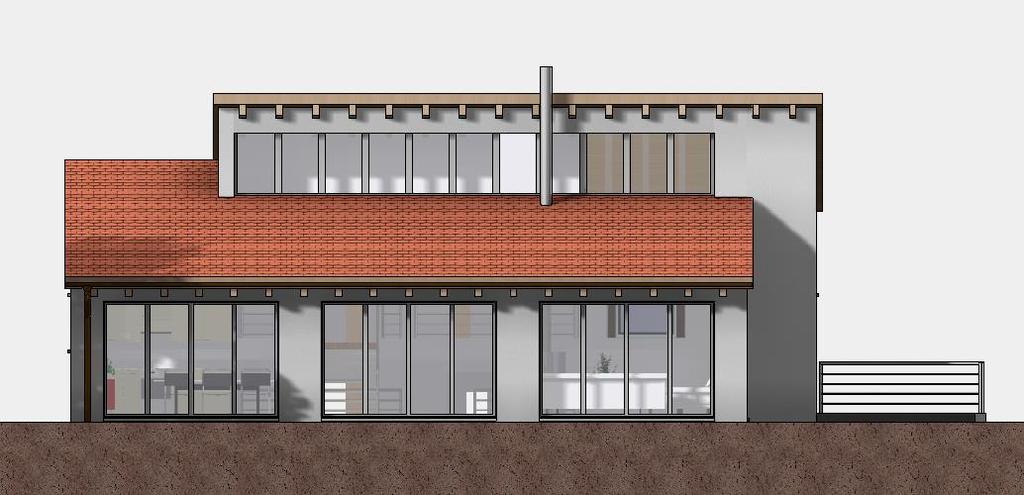
40 4. Create new view. 5. Adjust the following settings. 6. Next, open the render parameters on the same screen, adjust the following settings and close the screen by clicking OK. 7. Close the main screen with OK. The view will be calculated. 8. Load the "South façade" view onto the screen. 39


41 WORKSHOP END South façade The view can continue to be enhanced with 2D library parts. Display EXPLANATION You can use this button to determine whether, for the view, a solid image or render image is defined or not, in addition to the lines. Hidden line Only lines are displayed. Solid The colour surfaces are added to the background of the line display. Render The render image is added to the background of the line display. 40

42 DEFINE CUT-OUT If you right-click in the view, a menu item "Define cut-out" appears or, if one is already present, "Modify cut-out " and "Remove cut-out ". The function "Define section" determines an area to which the visibility of the view is restricted. Partial areas can therefore be defined from larger views. If you click "Modify section" the handles of the limitation framework become visible on which the section can be changed. Click "Remove section" to delete the limitation framework. WORKSHOP 1. Load the "South façade" view onto the screen. 2. Right-click in the view and select the point "Define cut out". 3. Drag the rectangle across P1 to P
 that continues to cover these lines and is not printed out. 5. Refresh view.")
43 P P 4. Delete the 4 view lines with the function DELETE SEGMENT. This deletion generates a deletion line (blue) that continues to cover these lines and is not printed out. 5. Refresh view. 6. Save work copy [Ctrl]+[W] WORKSHOP END 42
44 43


45 DEFINE PLOT WORKSHOP 1. Create new plot. Enter a name and the format and confirm with OK. 2. Set plan edge. In the menu click "LAY-OUT > FORMAT FRAME. 3. INSERT VIEW Click on the "Exterior view" and then on OK. 44


46 4. Set the view to the top left. 5. The view is too large. Load the model view "Exterior view". 6. Change the scale to 1: Load the plot view onto the screen. 45
47 8. PLACE VIEW Insert the views "Interior view" and "South façade". 9. Align views. Click on the view in question and position it. The function remains active and can be carried out for as long as required until it is cancelled with [Esc]. 10. Save work copy [Ctrl]+[W] WORKSHOP END TIP In the plot, the render images can also be combined with normal vector plans. 46

48 MODIFY SECTION (PLOT) Within the plot it is also possible to work directly in the sub views. WORKSHOP 1. Load the plot view onto the screen. 2. Double-click on the limitation framework of the south façade. The frame is highlighted red in this condition. 3. Right-click in the view and select the point "Modify cut-out". 4. Widen the view using the handles created and align with the others. 47

49 5. Update the view within the plot. If need be, execute the radiosity update. 6. To deactivate the view, either left-click outside this view in the plot or click on the name of the plot in views management. WORKSHOP END 48


50 CALCULATE FINAL IMAGES The quality of the images can be adjusted to your requirements. Do not set the quality unnecessarily high while working. Only do so before rendering the final image. Be also advised to lower the quality of the images when editing the project for long periods, and to increase it again when you are finished. The level of quality that can be set depends on your computer and its RAM. The size of your model is also a factor. If an image can no longer be calculated, a message appears on the screen. If this happens, the quality must be lowered. In the CAD_Object6 example file, the quality is set to half of that in the description for space reasons on the DVD. WORKSHOP 1. Load the model view "Exterior view". Ensure that the image is rendered. 2. Access screen parameters, modify the following settings and then close the screen with OK. 3. Refresh view. If need be, execute the radiosity update. 49

51 4. Do the same for the view "Interior view" as well. 5. For the "South façade" you reach the rendering parameters via the general screen parameters since the view is not a pure rendering. Set the same settings there as well but remain with the "Resolution" for image quality. Next, close both screens with OK. 6. Refresh view. If need be, execute the radiosity update. 7. Save work copy [Ctrl]+[W] WORKSHOP END 50
52 SAVE IMAGE Rendered model views can be saved as an image file. WORKSHOP 1. Load the model view "Exterior view". Ensure that the image is rendered. 2. In the menu "File > File exchange" select the point "Write pixel format ". 3. The "Write pixel format" screen opens. Enter a file name and confirm it with "Save". The image will be saved in the selected folder as an image file. 51

53 4. Do the same for the view "Interior view" as well. 5. The procedure is slightly different for the "South façade". Since the view is not pure rendering and also contains lines, the resolution must be entered manually. Load the view "South façade" onto the screen and from the menu "File > File exchange" select the menu item "Write pixel format". Enter the pixel size as follows: 6. Right-click in the view and select the point "Print preview". 7. Click OK to confirm the screen "Write pixel format". The "Write pixel format" screen opens. Enter a file name and confirm it with "Save". The image will be saved in the selected folder as an image file. 52

54 WORKSHOP END TIP For "Write bitmap" for normal views, always use the aspect ratio of the image. 53

55 PRINT If colour gradient hatches or transparencies exist in plans, certain printer drivers may not print them as transparent. In this case, the option "Print in highest quality" must be selected in the SETTINGS menu > SYSTEM > CONFIGURATION. WORKSHOP 1. Load the plot view onto the screen. 2. Click on the PRINT symbol. 3. Print on format size A2: Select the relevant printer or plotter, select the format under "Properties" and under "Range" select "Format". 4. Print on format size A3: Select the relevant printer or plotter, select the format under "Properties" and under "Range" select both "Format" and also the "Modify" option. 54
56 5. Save the file. WORKSHOP END 55
COURSE UNIT 1. Beginners MESSERLI ELITECAD VERSION
 MESSERLI ELITECAD VERSION 13 27.09.2013 COURSE UNIT 1 Switzerland: Austria: Germany: Messerli Informatik AG Messerli Informatik GmbH Messerli Informatik GmbH Pfadackerstrasse 6 Hamoderstraße 4 Konrad-Adenauer-Straße
13/02/2008. Users guide RoofCon Viewer
 Users guide RoofCon Viewer Table of contents Users guide RoofCon Viewer... 1 Table of contents... 2 Installation... 3 Select object... 3 Zoom... 3 Measure distance... 3 Toolbar and Drawing preferences...
SketchUp Starting Up The first thing you must do is select a template.
 SketchUp Starting Up The first thing you must do is select a template. While there are many different ones to choose from the only real difference in them is that some have a coloured floor and a horizon
AECOsim Building Designer Quick Start Guide
 AECOsim Building Designer Quick Start Guide Chapter A17 Rendering 2012 Bentley Systems, Incorporated www.bentley.com/aecosim Table of Contents Rendering...3 The Camera... 3 Materials... 5 Material Palettes...
SketchUp. SketchUp. Google SketchUp. Using SketchUp. The Tool Set
 Google Google is a 3D Modelling program which specialises in making computer generated representations of real-world objects, especially architectural, mechanical and building components, such as windows,
Chief Architect X10 New Feature List
 PRODUCTIVITY Saved Plan Views. Create and save multiple plan views (similar to saved cameras). Each view retains Layer Set, Annotation Set and Active Defaults. Open multiple Plan Views in Windows or Tabs,
With ClaroIdeas you can quickly and easily create idea maps using a combination of words, symbols and pictures.
 Welcome to ClaroIdeas ClaroIdeas is a fresh tool to support the creation and editing of concept maps or idea maps using visual and audio components. It has been specifically developed to support people
3D Architect Home Designer Getting Started Guide
 3D Architect Home Designer Getting Started Guide Produced and published in the UK by Eleco Software Limited 2016 Elecosoft plc. All rights reserved. The software and hardware names and labels used in this
Unit 21 - Creating a Navigation Bar in Macromedia Fireworks
 Unit 21 - Creating a Navigation Bar in Macromedia Fireworks Items needed to complete the Navigation Bar: Unit 21 - House Style Unit 21 - Graphics Sketch Diagrams Document ------------------------------------------------------------------------------------------------
Virtual MODELA USER'S MANUAL
 Virtual MODELA USER'S MANUAL Virtual MODELA is a program that simulates the movement of the tool on the screen. Contents Contents Part 1 Introduction 1-1 System Requirements... 4 1-2 Overview of Virtual
imos PLAN 2.0 We make every effort to ensure the content of this document is complete, accurate and up to date.
 imos PLAN 2.0 We make every effort to ensure the content of this document is complete, accurate and up to date. However, continuous development of the described software means it is not possible to guarantee
1 In the Mini Window Editor, double-click phase 1 (GF-Wall-External) to make it current:
 to make it current:") 1 This Quick Start tutorial introduces you to the basics of creating an intelligent drawing using the BIM components supplied with MicroGDS 2010. Here we demonstrate how to construct the external walls
1 This Quick Start tutorial introduces you to the basics of creating an intelligent drawing using the BIM components supplied with MicroGDS 2010. Here we demonstrate how to construct the external walls
Quick Crash Scene Tutorial
 Quick Crash Scene Tutorial With Crash Zone or Crime Zone, even new users can create a quick crash scene diagram in less than 10 minutes! In this tutorial we ll show how to use Crash Zone s unique features
Automatic PDF Refresh. PDF file references will refresh display when they have been externally updated, ensuring accuracy.
 PRODUCTIVITY / USER INTERFACE Revisions to 3D Viewer Files. Choose to update existing 3D Viewer models with newer revisions from Chief Architect, no need to manage multiple versions of the same project.
Virginia Western Community College ARC 221 Architectural CAD Applications Software I
 Virginia Western Community College ARC 221 Architectural CAD Applications Software I Prerequisites CAD 241 Course Description Teaches the principles and techniques of architectural drawing practices through
Bombardier Business Aircraft Customer Services. Technical Publications. SmartPubs Viewer 3.0 User Guide. Updated January 2013 [2013]
![Bombardier Business Aircraft Customer Services. Technical Publications. SmartPubs Viewer 3.0 User Guide. Updated January 2013 [2013]](/thumbs/90/103657167.jpg "Bombardier Business Aircraft Customer Services. Technical Publications. SmartPubs Viewer 3.0 User Guide. Updated January 2013 [2013]") Bombardier Business Aircraft Customer Services Technical Publications SmartPubs Viewer 3.0 User Guide Updated January 2013 [2013] Table of Contents Application Views... 5 Collection View... 5 Manual View...
Bombardier Business Aircraft Customer Services Technical Publications SmartPubs Viewer 3.0 User Guide Updated January 2013 [2013] Table of Contents Application Views... 5 Collection View... 5 Manual View...
Tutorial 14b: Advanced polygonal modeling
 Tutorial 14b: Advanced polygonal modeling Table of Contents................................... 3 2 Download items Tutorial data Tutorial PDF Part 1: Polygonal Modeling Note that you can also find a video
4) Finish the spline here. To complete the spline, double click the last point or select the spline tool again.
 Finish the spline here. To complete the spline, double click the last point or select the spline tool again.") 1) Select the line tool 3) Move the cursor along the X direction (be careful to stay on the X axis alignment so that the line is perpendicular) and click for the second point of the line. Type 0.5 for
1) Select the line tool 3) Move the cursor along the X direction (be careful to stay on the X axis alignment so that the line is perpendicular) and click for the second point of the line. Type 0.5 for
Materials Tutorial. Chapter 4: Setting Materials Defaults
 Chapter 4: Materials Tutorial Materials display on the surfaces of objects in 3D views and can make a 3D view appear highly realistic. When applied to most objects, material quantities will also be calculated
ezimagex2 User s Guide Version 1.0
 ezimagex2 User s Guide Version 1.0 Copyright and Trademark Information The products described in this document are copyrighted works of AVEN, Inc. 2015 AVEN, Inc. 4595 Platt Rd Ann Arbor, MI 48108 All
Autodesk Viz Render Illuminated Speaker; Charles Busa
 December 2-5, 2003 MGM Grand Hotel Las Vegas Autodesk Viz Render Illuminated Speaker; Charles Busa BD3-3 Autodesk Viz Render Illuminated This course is an introduction to the new Autodesk VIZ Render. Learn
imos Drawing Output The following document includes the topics borders and viewsets.
 imos Drawing Output The following document includes the topics borders and viewsets. We have attempted to keep the content of the document complete, accurate and under permanent review. However, due to
Import / Object modes: 5 Layers for organising your scene are available at the top of the screen.
 LUMION 1 VS LUMION 2 SCENES - In Lumion 2, the sky, clouds, fog, material settings, ambient shadows and reflections have been overhauled, so don't expect your Lumion 1 scenes to look identical when you
Home Designer Update Notes
 Home Designer 18.3.2.2 Update Notes October 28, 2016 1 General Notes This is a list of the changes made to Home Designer 2017 in the 18.3.2.2, 18.3.1.2, 18.3.0.47, 18.2.1.2, 18.2.0.42, and 18.1.1.4 program
DCN Synoptic Microphone Control. Software User Manual en LBB 3571
 DCN en LBB 3571 GENERAL CONTENTS Chapter 1-1.1 About 1.2 What is a synoptic layout? 1.3 Controlling microphones Chapter 2 - Getting Started 2.1 Starting 2.2 Using Help Chapter 3 - Preparing for a Conference
Basic Tutorials Series: Navigating the Software. RenoWorks Support Team Document #HWPRO0002
 Basic Tutorials Series: Navigating the Software RenoWorks Support Team Document #HWPRO0002 Navigating the software 2 1 Opening the Software Opening the Software There are two ways to open the program and
Layout Tutorial. Getting Started. Creating a Layout Template
 Layout Tutorial This tutorial will explain how create a layout template, send views to a layout page, then save the document in PDF format. In this tutorial you will learn about: Creating a Layout Template
EXERCISE 6: AEC OBJECTS
 EXERCISE 6: AEC OBJECTS ASSIGNMENT: In this exercise you will create a small pavilion using AEC extended objects, Doors, Windows and Stairs LEARNING OBJECTIVES: Modeling with AEC Objects Using Door, Windows,
Creating a New Plan File
 1 Tutorial NAME Creating a New Plan File 2 The first step in creating your own design is to open and name a new plan file. 1. From the MENU BAR, select File, New Plan. 2. From the MENU BAR, select File,
XnView Image Viewer. a ZOOMERS guide
 XnView Image Viewer a ZOOMERS guide Introduction...2 Browser Mode... 5 Image View Mode...14 Printing... 22 Image Editing...26 Configuration... 34 Note that this guide is for XnView version 1.8. The current
Using SymPrint to Make Overlays, Templates & More...
 Welcome to SymPrint SymPrint is an easy-to-use tool for creating communication overlays, worksheets, classroom activities and more using a modern toolbar and common-sense interface modeled after the programs
3 AXIS STANDARD CAD. BobCAD-CAM Version 28 Training Workbook 3 Axis Standard CAD
 3 AXIS STANDARD CAD This tutorial explains how to create the CAD model for the Mill 3 Axis Standard demonstration file. The design process includes using the Shape Library and other wireframe functions
Introduction Panning the View...9 Zooming the View...9 Zooming into the Selection...10 Zooming into a Rectangle...10 Adding Objects...
 Copyright Hengestone Holdings, Inc. All Rights Reserved. Copyright Idea Spectrum, Inc. All Rights Reserved. Idea Spectrum, and the Idea Spectrum logo are all trademarks of Idea Spectrum, Inc. Windows is
Autodesk Navisworks Freedom Quick Reference Guide
 WP CAD 00074 March 2012 Guide by Andy Davis Autodesk Navisworks Freedom Quick Reference Guide Quick Reference Guide to Autodesk Navisworks Freedom Opening a Model To open a model, click on the Application
1 General Principles. General Principles. In this chapter 1-1
 1 General Principles In this chapter 1 General Principles 1.1 User Interface 1.2 Title bar 1.3 Menu bar 1.4 Standard Toolbar 1.5 The drawing area 1.6 Component tabs 1.7 Status Bar 1.8 Manipulating Components
Revit 2018 Architecture Certification Exam Study Guide
 ELISE MOSS Autodesk Autodesk Certified Instructor Revit 2018 Architecture Certification Exam Study Guide Certified User and Certified Professional SDC P U B L I C AT I O N S Better Textbooks. Lower Prices.
WIRE BASICS ESTIMATED TIME REQUIRED. This tutorial will teach you the basics of sketching wires and using them as contours for solid objects.
 WIRE BASICS This tutorial will teach you the basics of sketching wires and using them as contours for solid objects. ESTIMATED TIME REQUIRED 30 Minutes LEARNING GOALS In this tutorial you will learn how
Chief Architect X Update Notes
 Chief Architect X3.4.2.7 Update Notes February 2, 2011 1 GENERAL NOTES This is a list of the changes made to Chief Architect X4 in the 13.1.2.3, 13.2.0.49, 13.3.2.20, 13.4.1.22 and 13.4.2.7 program updates.
Chief Architect X Update Notes
 Chief Architect X9.2.0.39 Update Notes March 23, 2017 1 General Notes This is a list of the changes made to Chief Architect X9 in the 19.2.0.39, 19.1.0.47 and 19.0.3.50 program update. 2.1 Program Overview
1st Point. 2nd Point. hold shift & drag along Y. Splines
 Splines STEP 1: open 3DS Max _ from the Command Panel under the Create tab click on Shapes (note: shapes are really Splines) _ under Object Type click on Ellipse STEP 2: Expand the Keyboard Entry tab type
Textures and UV Mapping in Blender
 Textures and UV Mapping in Blender Categories : Uncategorised Date : 21st November 2017 1 / 25 (See below for an introduction to UV maps and unwrapping) Jim s Notes regarding Blender objects, the UV Editor
Materials Tutorial. Setting Materials Defaults
 Materials Tutorial Materials display on the surfaces of objects in 3D views and can make a 3D view appear highly realistic. When applied to most objects, material quantities will also be calculated in
Draw Guide. Chapter 7 Working with 3D Objects
 Draw Guide Chapter 7 Working with 3D Objects Copyright This document is Copyright 2011 2014 by the LibreOffice Documentation Team. Contributors are listed below. You may distribute or modify it under the
PLAY VIDEO. Fences can be any shape from a simple rectangle to a multisided polygon, even a circle.
 Chapter Eight Groups PLAY VIDEO INTRODUCTION There will be times when you need to perform the same operation on several elements. Although this can be done by repeating the operation for each individual
COS 116 The Computational Universe Laboratory 10: Computer Graphics
 COS 116 The Computational Universe Laboratory 10: Computer Graphics As mentioned in lecture, computer graphics has four major parts: imaging, rendering, modeling, and animation. In this lab you will learn
Insight: Measurement Tool. User Guide
 OMERO Beta v2.2: Measurement Tool User Guide - 1 - October 2007 Insight: Measurement Tool User Guide Open Microscopy Environment: http://www.openmicroscopy.org OMERO Beta v2.2: Measurement Tool User Guide
BASICS OF MOTIONSTUDIO
 EXPERIMENT NO: 1 BASICS OF MOTIONSTUDIO User Interface MotionStudio combines draw, paint and animation in one easy easy-to-use program gram to save time and make work easy. Main Window Main Window is the
TSS. Event CAD Tutorial. Event Hire Software. Software Solutions for the Event Hire Industry. 2D/3D Layout and Presentation. T S Solutions Limited
 Event Hire Software - Software Solutions for the Event Hire Industry - Event CAD Tutorial 2D/3D Layout and Presentation T S Solutions Limited T S Solutions Limited Tel: 0117 956 4571 Email: info@tssweb.net
2014 Simplify3D. Quick Start Guide
 Quick Start Guide Preparation Installing Simplify3D Software 3 The Configuration Assistant 4 The Interface Layout 5 3D Printing Workflow Import Process Settings Preview Print! Import 7 Process Settings
SWITCHING FROM SKETCHUP TO VECTORWORKS
 SWITCHING FROM SKETCHUP TO VECTORWORKS INTRODUCTION There are a lot of 3D modeling software programs to choose from and each has its own strengths and weaknesses. For architects, flexibility and ease of
Contents. Introduction... 4
 Copyright Idea Spectrum, Inc. All Rights Reserved. Realtime Landscaping Architect, the Realtime Landscaping Architect logo, Idea Spectrum, and the Idea Spectrum logo are all trademarks of Idea Spectrum,
Materials Tutorial. Setting Materials Defaults
 Materials Tutorial Materials display on the surfaces of objects in 3D views and can make a 3D view appear highly realistic. When applied to most objects, material quantities will also be calculated in
Autodesk Fusion 360 Training: The Future of Making Things Attendee Guide
 Autodesk Fusion 360 Training: The Future of Making Things Attendee Guide Abstract After completing this workshop, you will have a basic understanding of editing 3D models using Autodesk Fusion 360 TM to
Revit Architecture 2015 Basics
 Revit Architecture 2015 Basics From the Ground Up Elise Moss Authorized Author SDC P U B L I C AT I O N S Better Textbooks. Lower Prices. www.sdcpublications.com Powered by TCPDF (www.tcpdf.org) Visit
COS 116 The Computational Universe Laboratory 10: Computer Graphics
 COS 116 The Computational Universe Laboratory 10: Computer Graphics As mentioned in lecture, computer graphics has four major parts: imaging, rendering, modeling, and animation. In this lab you will learn
Computer graphics Labs: Blender (1/3) Modelling, transparency and reflection
 Modelling, transparency and reflection") Computer graphics Labs: Blender (1/3) Modelling, transparency and reflection University of Liège Department of Aerospace and Mechanical engineering Designed with Blender 2.76b Introduction to the interface
Computer graphics Labs: Blender (1/3) Modelling, transparency and reflection University of Liège Department of Aerospace and Mechanical engineering Designed with Blender 2.76b Introduction to the interface
Tutorial 4: Texture Mapping Techniques
 Tutorial 4: Texture Mapping Techniques Completion time 40 minutes In the previous tutorial we learned how to create materials, and how to assign texture maps to those materials. In this tutorial we will
Lighting Techniques 1
 STEP 1: open your Class-05 Max fi le _ main menu / Customize / Units Setup _ set Display Unit Scale as shown in Image 1 _ set Lighting Units to: American STEP 2: select Daylight.01 _ command panel / modify
1. Introduction and system and hardware requirements
 Table of Contents 1. Introduction and system and hardware requirements... 3 2. Installation of the Wardrobe Module... 4 3. Starting work with the module... 7 3.1. Introduction... 7 3.2. Basic Options Wizard
solidthinking Environment...1 Modeling Views...5 Console...13 Selecting Objects...15 Working Modes...19 World Browser...25 Construction Tree...
 Copyright 1993-2009 solidthinking, Inc. All rights reserved. solidthinking and renderthinking are trademarks of solidthinking, Inc. All other trademarks or service marks are the property of their respective
Easy View Manual Nicolaudie-Sunlite
 1989-2004 Nicolaudie-Sunlite Table of Contents Part I Preface Part II 3D Visualizer 1 2... 2 1 First steps Menu... 2 Toolbar... 3 Mouse move... 4... 5 2 3D stage Your first stage... 5... 7 3 Stage settings
Home Designer Update Notes
 Home Designer 17.3.2.2 Update Notes October 14, 2015 1 General Notes This is a list of the changes made to Home Designer 2016 in the 17.3.2.2, 17.3.1.1, 17.3.0.25, 17.2.0.69, 17.1.2.2, 17.1.1.3, and 17.1.0.51
Transforming Objects and Components
 4 Transforming Objects and Components Arrow selection Lasso selection Paint selection Move Rotate Scale Universal Manipulator Soft Modification Show Manipulator Last tool used Figure 4.1 Maya s manipulation
AUTODESK FUSION 360 Designing a RC Car Body
 AUTODESK FUSION 360 Designing a RC Car Body Abstract This project explores how to use the sculpting tools available in Autodesk Fusion 360 Ultimate to design the body of a RC car. John Helfen john.helfen@autodesk.com
Microsoft Word Training
 Microsoft Word Training Objectives: Become familiar with the Word Window, toolbars, and menus Learn to Save and Print Learn how to create tables, forms and templates Opening Word / Menus / Toolbars Click
General Information Project management Introduction... 4 Getting Started Input geometry... 7
 Tutorial Shell Tutorial Shell All information in this document is subject to modification without prior notice. No part or this manual may be reproduced, stored in a database or retrieval system or published,
SunCast - User Guide. IES Virtual Environment 2013
 SunCast - User Guide IES Virtual Environment 2013 Contents 1 Introduction to SunCast... 3 1.1 SunCast Features...3 1.2 Getting Help...3 2 Starting SunCast... 3 2.1 Application Bar...3 2.2 Mode...4 3 The
Updated April 28, 2010
 Performance Chief Architect download is faster and more efficient now that Library Catalogs are download on demand and can be mass downloaded or on an as needed basis. New Ray Trace Rendering Engine. Enhanced
Controlling the Drawing Display
 Controlling the Drawing Display In This Chapter 8 AutoCAD provides many ways to display views of your drawing. As you edit your drawing, you can control the drawing display and move quickly to different
XnView 1.9. a ZOOMERS guide. Introduction...2 Browser Mode... 5 Image View Mode...15 Printing Image Editing...28 Configuration...
 XnView 1.9 a ZOOMERS guide Introduction...2 Browser Mode... 5 Image View Mode...15 Printing... 22 Image Editing...28 Configuration... 36 Written by Chorlton Workshop for hsbp Introduction This is a guide
Table of contents. I Preface. II First steps 1. 3D stage 2. Your first stage
 Table of contents I Preface 1 II First steps 3 1. 3D stage 2. Your first stage III User mode 2 3 7 1. Rendering options 2. Resolution 3. Cameras 4. DMX levels 5. Universes patch 6. Movie recorder 6 7 7
Quick Start Guide. ASR Automated Systems Research Inc. Toll free: Fax:
 Quick Start Guide ASR Automated Systems Research Inc. Toll free: 1-800-818-2051 Phone: 604-539-0122 e-mail: support@asrsoft.com Fax: 604-539-1334 www.asrsoft.com Copyright 1991-2014 ASR Automated Systems
LIGHTCONVERSE TOOLS Interface Overview
 MANUAL 1 Contents Contents... 1 LIGHTCONVERSE TOOLS Interface Overview... 2 Tool Manager... 3 Mouse... 4 Mouse Control Operation:... 4 3D Space Area... 4 Modes... 5 Balance Calculator in Warehouse Mode...
How to make a scene for products with the help of Album3DEngine
 How to make a scene for products with the help of Album3DEngine Designer guide Contents Introduction... 1 Required software... 2 Creating a gallery... 2 Step 1: Modeling with 3ds Max... 2 Step 2: Creating
ccassembler 3.1 Getting Started
 ccassembler 3.1 Getting Started Dated: 31.03.2017 www.cadclick.de - 1 - KiM GmbH 1 Basic Principles... 6 1.1 Installing anchor on anchor... 6 1.2 Modes and Actions... 7 1.3 Mouse control and direct input...
Lesson 1 Parametric Modeling Fundamentals
 1-1 Lesson 1 Parametric Modeling Fundamentals Create Simple Parametric Models. Understand the Basic Parametric Modeling Process. Create and Profile Rough Sketches. Understand the "Shape before size" approach.
CROMWELLSTUDIOS. Content Management System Instruction Manual V1. Content Management System. V1
 Content Management System Instruction Manual V1 www.cromwellstudios.co.uk Cromwell Studios Web Services Content Management System Manual Part 1 Content Management is the system by which you can change
Chief Architect Home Designer Interiors User s Guide
 Chief Architect Home Designer Interiors 2019 User s Guide Chief Architect, Inc. 6500 N. Mineral Dr. Coeur d Alene, Idaho 83815 HomeDesignerSoftware.com 1990 2018 by Chief Architect, Inc. All rights reserved.
Materials Tutorial. Setting Materials Defaults
 Materials Tutorial Materials display on the surfaces of objects in 3D views and can make a 3D view appear highly realistic. When applied to most objects, material quantities will also be calculated in
Materials Tutorial. Setting Materials Defaults
 Materials Tutorial Materials display on the surfaces of objects in 3D views and can make a 3D view appear highly realistic. When applied to most objects, material quantities will also be calculated in
Basic Modeling 1 Tekla Structures 12.0 Basic Training September 19, 2006
 Tekla Structures 12.0 Basic Training September 19, 2006 Copyright 2006 Tekla Corporation Contents Contents 3 1 5 1.1 Start Tekla Structures 6 1.2 Create a New Model BasicModel1 7 1.3 Create Grids 10 1.4
Revit 2017 Architecture Certification Exam Study Guide
 ELISE MOSS Autodesk Autodesk Certified Instructor Revit 2017 Architecture Certification Exam Study Guide Certified User and Certified Professional SDC P U B L I C AT I O N S Better Textbooks. Lower Prices.
Security Management System Object Counting
 Security Management System Object Counting This document describes the steps for using the Object Counting module available in the Security Management System software. (A) Object Counting Configuration
Contents. Introduction... 4
 Copyright 2008 Idea Spectrum, Inc. All Rights Reserved. Realtime Landscaping Plus, the Realtime Landscaping Plus logo, Idea Spectrum, and the Idea Spectrum logo are all trademarks of Idea Spectrum, Inc.
Quick Start Guide. ARIS Architect. Version 9.8 Service Release 2
 ARIS Architect Version 9.8 Service Release 2 October 2015 This document applies to ARIS Version 9.8 and to all subsequent releases. Specifications contained herein are subject to change and these changes
Window Designer. Opening Screen: When you start Window Designer, you will see the Opening Screen. Here you will be choosing from 4 options:
 Window Designer Opening Screen: When you start Window Designer, you will see the Opening Screen. Here you will be choosing from 4 options: New Design: Use this option when no pre-built templates are available
Getting Started with ShowcaseChapter1:
 Chapter 1 Getting Started with ShowcaseChapter1: In this chapter, you learn the purpose of Autodesk Showcase, about its interface, and how to import geometry and adjust imported geometry. Objectives After
ActivPanel. User Guide for Staff. Produced by C&IT Services
 ActivPanel User Guide for Staff Produced by C&IT Services TABLE OF CONTENTS TABLE OF CONTENTS... 2 OVERVIEW... 4 1.0 WHERE CAN I USE ACTIVPANEL?... 4 2.0 THE ACTIVPANEL COMPONENTS... 5 2.1 THE LCD TABLET...
BSc Computing Year 3 Graphics Programming 3D Maze Room Assignment Two. by Richard M. Mann:
 BSc Computing Year 3 Graphics Programming 3D Maze Room Assignment Two by Richard M. Mann: 20032144 April 2003 Table of Contents 1 INTRODUCTION...4 2 ANALYSIS & DESIGN...5 2.1 ROOM DESIGN... 5 2.1.1 Dimensions...5
CHAPTER 1 COPYRIGHTED MATERIAL. Getting to Know AutoCAD. Opening a new drawing. Getting familiar with the AutoCAD and AutoCAD LT Graphics windows
 CHAPTER 1 Getting to Know AutoCAD Opening a new drawing Getting familiar with the AutoCAD and AutoCAD LT Graphics windows Modifying the display Displaying and arranging toolbars COPYRIGHTED MATERIAL 2
Pagoda/Hypar 3. Manual
 Pagoda/Hypar 3 Manual Armstrong-White Automation (NZ) Ltd Armstrong-White Automation (NZ) Ltd 22 Kereru Grove, Greenhithe, North Shore City 0632 (Auckland), New Zealand. ph +64 9 413-7642 fax +64 9 413-7643
GETTING STARTED GUIDE NOW THAT YOU RE HERE LET S GET STARTED
 GETTING STARTED GUIDE NOW THAT YOU RE HERE LET S GET STARTED VECTORWORKS SPOTLIGHT GETTING STARTED GUIDE Vectorworks Spotlight Getting Started Guide Created using: Vectorworks Spotlight 2016 2016 Nemetschek
Mapping Environments Project 4 Modern Maps
 880106 Mapping Environments Project 4 Modern Maps Week 08-09: When Engineering Design Labs & University Campus: Where Group of 4: Who 15%: Worth 1 Aim: The overarching aim of this project is to introduce
GEOCIRRUS 3D Viewer. User Manual: GEOCIRRUS 3D Viewer Document version 1.6 Page 1
 GEOCIRRUS 3D Viewer Page 1 Table of Contents 3D Viewer Functionality... 3 Line of Sight (LoS)... 4 Identify... 8 Measurement... 9 3D Line Measure Tool... 10 3D Area Measure Tool... 11 Environment... 12
Microsoft Visio Working with Shapes
 Working with Visio Shapes Shape is the general term for the objects you will find on a stencil and objects created using the drawing tools. These include geometric shapes such as rectangles, triangles
3ds Max Cottage Step 1. Always start out by setting up units: We re going with this setup as we will round everything off to one inch.
 3ds Max Cottage Step 1 Always start out by setting up units: We re going with this setup as we will round everything off to one inch. File/Import the CAD drawing Be sure Files of Type is set to all formats
AGi32 version 2.3. Keyboard Shortcuts (cntd.) General. Function Keys. Mouse Functions. Keyboard Shortcuts F1 F2 F3 F4 F5 F6 F7 F8 F9 F10 F11 F12
 General. Function Keys. Mouse Functions. Keyboard Shortcuts F1 F2 F3 F4 F5 F6 F7 F8 F9 F10 F11 F12") Function Keys Help Viewpoints - Quick Add Snap To Arc F1 F2 F3 F4 F5 F6 F7 F8 F9 F10 F11 F12 Mouse Functions Left click: Select L R Keyboard Shortcuts Left Arrow Right Arrow Up Arrow Down Arrow Shift+
Function Keys Help Viewpoints - Quick Add Snap To Arc F1 F2 F3 F4 F5 F6 F7 F8 F9 F10 F11 F12 Mouse Functions Left click: Select L R Keyboard Shortcuts Left Arrow Right Arrow Up Arrow Down Arrow Shift+
Introduction to Google SketchUp
 Introduction to Google SketchUp When initially opening SketchUp, it will be useful to select the Google Earth Modelling Meters option from the initial menu. If this menu doesn t appear, the same option
Stamina Software Pty Ltd. TRAINING MANUAL Viságe Reporter
 Stamina Software Pty Ltd TRAINING MANUAL Viságe Reporter Version: 2 21 st January 2009 Contents Introduction...1 Assumed Knowledge...1 Pre Planning...1 Report Designer Location...2 Report Designer Screen
Beginners Guide to Snippet Master PRO
 Beginners Guide to Snippet Master PRO This document assumes that Snippet Master has been installed on your site. If not please contact the Bakas IT web team at webreg@bakasit.com.au. Initial Login Screen...