Current Status of Isogeometric Analysis in LS-DYNA
|
|
|
- Helen Ball
- 5 years ago
- Views:
Transcription


1 Current Status of Isogeometric Analysis in LS-DYNA Stefan Hartmann Developer Forum, September 24 th, 2013, Filderstadt, Germany Development in cooperation with: D.J. Benson: Professor of Applied Mechanics, University of California, San Diego, USA
2 Outline Isogeometric Analysis - motivation / definition NURBS-based finite elements - NURBS / *ELEMENT_SHELL_NURBS_PATCH / elements - connectivity Shell formulations - continuity / rotation free shells / blended shells Contact with NURBS - smoothness / example Current status - MPP / examples / limits / LSPP / Todo-List - mass-scaling / merging / trimmed NURBS / NURBS-solids / LSPP /
3 Isogeometric Analysis motivation & definition reduce effort of geometry conversion from CAD into a suitable mesh for FEA (?) reduce discretization errors adaptivity increase continuity of geometry representation contact / rot. free shells / ISOPARAMETRIC (FE-Analysis) use same approximation for geometry and deformation GEOMETRY DEFORMATION ISOGEOMETRIC (CAD - FEA) same description of the geometry in the design (CAD) and the analysis (FEA) CAD FEA common geometry descriptions in CAD - NURBS (Non-Uniform Rational B-splines) most commonly used - T-splines enhancement of NURBS - subdivision surfaces mainly used in animation industry - and others
 - refinement (h/p and k) without changing the initial geometry adaptivity - control points are normally not a part of the physical")
4 NURBS-based finite elements NURBS = Non Uniform Rational Basis Spline B-spline basis functions - recursive - positive everywhere - dependent on knot-vector and polynomial order - normally C (P-1) -continuity - partition of unity (like Lagrange polynomials) - refinement (h/p and k) without changing the initial geometry adaptivity - control points are normally not a part of the physical geometry (non-interpolatory basis functions) NURBS - B-spline basis functions + control net with weights - all mentioned properties for B-splines apply for NURBS A typical NURBS-Patch and the elements - elements are defined through the knot-vectors - shape functions for each control-point (DOFs) Control-Points Control-Net Elements
5 NURBS-based finite elements *ELEMENT_SHELL_NURBS_PATCH $---+--EID PID NPR PR NPS PS $---+--WFL----+-FORM INT----+-NISR----+-NISS----+IMASS $rk $sk $net+---n n n n n n n n Control Points Control Net s Elements 1 r 2 x z y 3 4 8
6 NURBS-based finite elements A typical NURBS-Patch and the definition of elements - elements are defined through the knot-vectors (interval between different values) - shape functions for each control-point x z y polynomial order: - quadratic in r-direction (pr=2) - quadratic in s-direction (ps=2) s s r NURBS-Patch (physical space) Control-Points sknot=[0,0,0,1,2,3,3,3] M 5 M 4 M 3 M 2 M N 1 N2 N 3 N 4 r Control-Net Element NURBS-Patch (parameter space) rknot=[0,0,0,1,2,2,2]
7 NURBS-based finite elements 31 Nurbs-Surface (physical space) s r Control Points (*NODE) Control Net (*ELEMENT_SHELL_NURBS_PATCH) Connectivity of Nurbs-Element (automatic) Nurbs-Element (automatic) Interpolation Node (automatic) Interpolation Element (automatic) from: LS-DYNA KEYWORD USER S MANUAL VOLUME I Nurbs-Surface (parameter space) B-spline basis functions (s-direction) s-knot: [0,0,0,1,2,2,2] s r Interpolation Elements (postprocessing/contact/bc) NISR=2 / NISS=2 Livermore Software Technology Corporation (LSTC) B-spline basis functions (r-direction) r-knot: [0,0,0,1,2,3,4,5,6,7,7,7]
 vs.")
 NURBS")
8 Shell formulations continuity at element boundary - Lagrange: C 0 - NURBS: C p-1 support of shape functions (control points) do overlap FORM=0: - shear deformable shell theory with rotational DOFs (6DOFs/control point) vs. FORM=1: (requires C 1 ) - rotation free shell theory without rotational DOFs (3DOFs/control point) FORM=4/-4: - hybrid shell formulation combination of FORM=0 and FORM=1 (especially necessary at patch boundaries where continuity drops to C 0 ) NURBS (bi-quadratic) C 1 -lines LAGRANGE (bi-quadratic)

 Two patches (rot-free, coupled) Two patches (rot-free, kink) Kink!")
9 Shell formulations multi-patch coupling (rotation free formulation) G 1 continuity along patch boundaries - at patch boundaries: C 0 -lines (no transmission of bending moments with rot-free formulation) - add rotational DOFs at patch boundary (hybrid/blended shell: FORM=4/-4) One single patch (rot-free) Two patches (rot-free, coupled) Two patches (rot-free, kink) Kink! Kink!
 keep angle at discontinuities (internal C 0")


10 Shell formulations multi-patch coupling (rotation free formulation) keep angle at discontinuities (internal C 0 -lines) - no transmission of bending moments with rot-free formulation kinks - add rotational DOFS at interior control points (FORM=4) rot-free (kink) coupling or formulation with rotational DOFs piano hinges 90 -angle Kink! 90 -angle
 - loss of smooth (contact) surface representation may lead to problems in tangential sliding interpolation shells (rough) NURBS")

11 Contact with NURBS all (penalty based) contacts available - use interpolation shell elements (lin. Quads) - loss of smooth (contact) surface representation may lead to problems in tangential sliding interpolation shells (rough) NURBS contact for (SMP only) *CONTACT_AUTOMATIC_1WAY_S2S - use NURBS representation on master side - smooth contact behavior (i.e. tangential sliding) interpolation shells (fine) NURBS-surface (smooth) *CONTROL_CONTACT $Optional $---SHLEDG----PSTIFF----ITHCNT----TDCNOF-----ftall shltrw----igactc 1
 - IGACTC=1: master surface defined by NURBS surface (smooth) - _SMOOTH: smooth curve-fitted surface")
 - termination time: t=0.1 v (r z ) 0.")
12 Contact with NURBS sliding example comparison *Contact_Automatic_One_Way_Surface_To_Surface - IGACTC=0: master surface defined by interpolation elements (faceted) - IGACTC=1: master surface defined by NURBS surface (smooth) - _SMOOTH: smooth curve-fitted surface to represent master surface Example: Tube-In-Tube (both elastic bodies properties of steel) - frictionless sliding - outer tube is fixed - inner tube is free to move - inner tube with initial rotational velocity (death: t=0.01) - termination time: t=0.1 v (r z ) 0.01 t y x z

13 Contact with NURBS sliding example discretization - inner tube: 8x12 bi-quadratic NURBS element - outer tube: 4x16 bi-quadratic NURBS element - 2x2 bi-linear interpolation shells per NURBS element Version A - inner tube is master - outer tube is slave y x z NURBS P P interpolation elements _SMOOTH IGACTC=0 IGACTC=1 free to rotate

14 Contact with NURBS sliding example discretization - inner tube: 8x12 bi-quadratic NURBS element - outer tube: 4x16 bi-quadratic NURBS element - 2x2 bi-linear interpolation shells per NURBS element Version B - inner tube is slave - outer tube is master y x z NURBS P P interpolation elements _SMOOTH IGACTC=0 IGACTC=1 free to rotate
 ncpu=1 _SMOOTH 8 min 43 sec 346484 6 min 10 sec (loss of contact at around t=0.")
15 Contact with NURBS sliding example computational time Version A Version B CPU time #of cycles CPU time #of cycles IGACTC=0 3 min 32 sec min 18 sec SMP (single) ncpu=1 IGACTC=1 9 min 27 sec min 55 sec SMP (single) ncpu=1 _SMOOTH 8 min 43 sec min 10 sec (loss of contact at around t=0.03) MPP (single) -np 1 NURBS contact (IGACTC=1) - insensitive to Slave-Master-Pair definition - more expensive than standard contact (IGACTC=0) but comparable with _SMOOTH option - NOTE: comparison is not representative (SMP vs. MPP), _SMOOTH option and Version B looses contact around t=0.03 (30% of computation time)
16 Current status - summary Keyword: *ELEMENT_SHELL_NURBS_PATCH - definition of NURBS-surfaces - shell formulations with/without rotational DOFs and hybrid shell - NURBS elements run in MPP with good scaling - NURBS contact (*CONTACT_AUTOMATIC_ONE_WAY_SURFACE_TO_SURFACE, IGACTC=1, SMP only) Pre- and Postprocessing - work in progress for LS-PrePost current status (lspp4.1beta) visualization of 2D-NURBS-Patches import IGES-format and construct *ELEMENT_SHELL_NURBS_PATCH modification of 2D-NURBS geometry much more to come! Postprocessing and boundary conditions (i.e. contact) mainly with - interpolation nodes (automatically created) - interpolation elements (automatically created) Analysis capabilities - implicit and explicit time integration - eigenvalue analysis - other capabilities (e.g. geometric stiffness for buckling) implemented but not yet tested LS-DYNA material library available (including umats)
17 Example Vibration of a square plate eigenvalue analysis - simply supported square plate - linear elastic material - consistent mass matrix - rotation free shell formulation L accuracy of first eigenvalue L Error=(Calculated-Exact)/Exact 1,0E+00 1,0E-02 1,0E-04 1,0E-06 1,0E-08 1,0E-10 1,0E-12 fully integrated shell (ELFORM=16) NURBS P=2 (rotation free) NURBS P=3 (rotation free) NURBS P=4 (rotation free) 1,0E Number of Nodes

 - Reissner-Mindlin formulation")


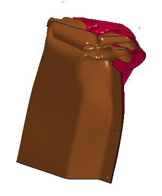
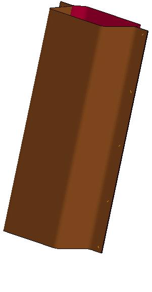
18 Example dynamic buckling nonlinear dynamic buckling - isotropic elastic-plastic material - linear plastic hardening - NURBS (P=2,3,4) - Reissner-Mindlin formulation Experimental results from Kyriakides S. Kyriakides, Personal communication, 2008 good agreement of - buckling load & buckling pattern - Reissner-Mindlin shell formulations (P=2,3,4)


19 Example - buckling standard benchmark for automobile crashworthiness quarter symmetry to reduce cost perturbation to initiate buckling mode J 2 plasticity with linear isotropic hardening mesh: quartic (P=4) elements control points - 3 integration points through thickness D.J. Benson

20 Example column crush spotweld modeling with *CONTACT_TIED_SHELL_EDGE_TO_SURFACE_OFFSET

21 Example - forming
22 Current status - limits regular NURBS-patch Control Points Control Net FEA: trimmed NURBS FEA: - standard in CAD 4 regular NURBS-patches trimming curve FEA: - reparametrization - C 0 -lines at patch boundaries
23 Summary NURBS-based elements run stable and scale good in MPP higher order accurate isogeometric analysis may be cost competitive code optimization necessary to make it faster NURBS contact works well model creation with standard NURBS is currently the bottleneck! ToDo-List perform a lot more studies in different fields experience motivate customers (and researchers) to play with these elements further implementation - post-processing directly with NURBS (partially available already) - mass scaling - NURBS contact implementation for MPP - merging of non-matching NURBS patches - trimmed NURBS (research currently done at UCSD) - make pre- and post-processing more user-friendly and faster - introduce 3D NURBS elements - much more
Frequency Domain Analysis for Isogeometric Element in LS-DYNA
 Frequency Domain Analysis for Isogeometric Element in LS-DYNA Liping Li 1, Yun Huang 1, Zhe Cui 1, Stefan Hartmann 2, David J. Benson 3 1 Livermore Software Technology Corporation, Livermore, CA, USA 2
Isogeometric Analysis Application to Car Crash Simulation
 Isogeometric Analysis Application to Car Crash Simulation S. Bouabdallah 2, C. Adam 2,3, M. Zarroug 2, H. Maitournam 3 De Vinci Engineering Lab, École Supérieure d Ingénieurs Léonard de Vinci 2 Direction
Recent Developments in Isogeometric Analysis with Solid Elements in LS-DYNA
 Recent Developments in Isogeometric Analysis with Solid Elements in LS-DYNA Liping Li David Benson Attila Nagy Livermore Software Technology Corporation, Livermore, CA, USA Mattia Montanari Nik Petrinic
Recent Advances on Higher Order 27-node Hexahedral Element in LS-DYNA
 14 th International LS-DYNA Users Conference Session: Simulation Recent Advances on Higher Order 27-node Hexahedral Element in LS-DYNA Hailong Teng Livermore Software Technology Corp. Abstract This paper
Modelling Flat Spring Performance Using FEA
 Modelling Flat Spring Performance Using FEA Blessing O Fatola, Patrick Keogh and Ben Hicks Department of Mechanical Engineering, University of Corresponding author bf223@bath.ac.uk Abstract. This paper
Example 24 Spring-back
 Example 24 Spring-back Summary The spring-back simulation of sheet metal bent into a hat-shape is studied. The problem is one of the famous tests from the Numisheet 93. As spring-back is generally a quasi-static
Solid and shell elements
 Solid and shell elements Theodore Sussman, Ph.D. ADINA R&D, Inc, 2016 1 Overview 2D and 3D solid elements Types of elements Effects of element distortions Incompatible modes elements u/p elements for incompressible
Recent Developments in LS-DYNA II
 9. LS-DYNA Forum, Bamberg 2010 Keynote-Vorträge II Recent Developments in LS-DYNA II J. Hallquist Livermore Software Technology Corporation A - II - 7 Keynote-Vorträge II 9. LS-DYNA Forum, Bamberg 2010
Distance Functions 1
 Distance Functions 1 Distance function Given: geometric object F (curve, surface, solid, ) Assigns to each point the shortest distance from F Level sets of the distance function are trimmed offsets F p
CHAPTER 4. Numerical Models. descriptions of the boundary conditions, element types, validation, and the force
 CHAPTER 4 Numerical Models This chapter presents the development of numerical models for sandwich beams/plates subjected to four-point bending and the hydromat test system. Detailed descriptions of the
Ultimate capacity analyses in LS-DYNA. Anders Jonsson,
 Ultimate capacity analyses in LS-DYNA Anders Jonsson, anders.jonsson@dynamore.se Ultimate capacity analyses in LS-DYNA A simplified cab frame roof crush load case Dimensions and model data Roof crush load
Revised Sheet Metal Simulation, J.E. Akin, Rice University
 Revised Sheet Metal Simulation, J.E. Akin, Rice University A SolidWorks simulation tutorial is just intended to illustrate where to find various icons that you would need in a real engineering analysis.
Linear Bifurcation Buckling Analysis of Thin Plate
 LESSON 13a Linear Bifurcation Buckling Analysis of Thin Plate Objectives: Construct a quarter model of a simply supported plate. Place an edge load on the plate. Run an Advanced FEA bifurcation buckling
Guidelines for proper use of Plate elements
 Guidelines for proper use of Plate elements In structural analysis using finite element method, the analysis model is created by dividing the entire structure into finite elements. This procedure is known
Introduction to 2 nd -order Lagrangian Element in LS-DYNA
 Introduction to 2 nd -order Lagrangian Element in LS-DYNA Hailong Teng Livermore Software Technology Corporation Nov, 2017 Motivation Users are requesting higher order elements for implicit. Replace shells.
Physically-Based Modeling and Animation. University of Missouri at Columbia
 Overview of Geometric Modeling Overview 3D Shape Primitives: Points Vertices. Curves Lines, polylines, curves. Surfaces Triangle meshes, splines, subdivision surfaces, implicit surfaces, particles. Solids
CHAPTER-10 DYNAMIC SIMULATION USING LS-DYNA
 DYNAMIC SIMULATION USING LS-DYNA CHAPTER-10 10.1 Introduction In the past few decades, the Finite Element Method (FEM) has been developed into a key indispensable technology in the modeling and simulation
Introduction to the Finite Element Method (3)
") Introduction to the Finite Element Method (3) Petr Kabele Czech Technical University in Prague Faculty of Civil Engineering Czech Republic petr.kabele@fsv.cvut.cz people.fsv.cvut.cz/~pkabele 1 Outline
Introduction to the Finite Element Method (3) Petr Kabele Czech Technical University in Prague Faculty of Civil Engineering Czech Republic petr.kabele@fsv.cvut.cz people.fsv.cvut.cz/~pkabele 1 Outline
Introduction to ANSYS LS-DYNA
 Lecture 12 Introduction to ANSYS LS-DYNA Extension 14.5 Release Introduction to ANSYS LS-DYNA 2012 ANSYS, Inc. November 8, 2012 1 Release 14.5 What is ANSYS LS-DYNA Extension ANSYS LS-DYNA in Workbench
Advances in LS-DYNA for Metal Forming (I)
") Advances in LS-DYNA for Metal Forming (I) Xinhai Zhu, Li Zhang, Yuzhong Xiao, and HouFu Fan Livermore Software Technology Corporation Abstract The following will be discussed: Enhancements in *CONTROL_FORMING_ONESTEP
Advances in LS-DYNA for Metal Forming (I) Xinhai Zhu, Li Zhang, Yuzhong Xiao, and HouFu Fan Livermore Software Technology Corporation Abstract The following will be discussed: Enhancements in *CONTROL_FORMING_ONESTEP
B-spline Curves. Smoother than other curve forms
 Curves and Surfaces B-spline Curves These curves are approximating rather than interpolating curves. The curves come close to, but may not actually pass through, the control points. Usually used as multiple,
Modeling Strategies for Dynamic Finite Element Cask Analyses
 Session A Package Analysis: Structural Analysis - Modeling Modeling Strategies for Dynamic Finite Element Cask Analyses Uwe Zencker, Günter Wieser, Linan Qiao, Christian Protz BAM Federal Institute for
LS-DYNA Implicit Workshop. Problem #1: Tensile Test
 LS-DYNA Implicit Workshop Problem #1: Tensile Test Objectives Learn how to activate LS-DYNA s implicit mode. Learn how to select linear or nonlinear analysis. Problem Description A static tensile test
Non-Linear Finite Element Methods in Solid Mechanics Attilio Frangi, Politecnico di Milano, February 3, 2017, Lesson 1
 Non-Linear Finite Element Methods in Solid Mechanics Attilio Frangi, attilio.frangi@polimi.it Politecnico di Milano, February 3, 2017, Lesson 1 1 Politecnico di Milano, February 3, 2017, Lesson 1 2 Outline
panelshop Solutions 2009 Version January 2009 icapp GmbH - Technoparkstrasse 1 - CH-8005 Zürich
 panelshop Solutions 2009 Version 9.0 30. January 2009 icapp GmbH - Technoparkstrasse 1 - CH-8005 Zürich www.icapp.ch contact@icapp.ch +41 43 818 2515 With the assistance of excellent tool and die shops
A Multiple Constraint Approach for Finite Element Analysis of Moment Frames with Radius-cut RBS Connections
 A Multiple Constraint Approach for Finite Element Analysis of Moment Frames with Radius-cut RBS Connections Dawit Hailu +, Adil Zekaria ++, Samuel Kinde +++ ABSTRACT After the 1994 Northridge earthquake
Modelling of Isogeometric Analysis for Plane Stress Problem Using Matlab GUI Norliyana Farzana Binti Zulkefli, Ahmad Razin Bin Zainal Abidin
 Modelling of Isogeometric Analysis for Plane Stress Problem Using Matlab GUI Norliyana Farzana Binti Zulkefli, Ahmad Razin Bin Zainal Abidin Faculty of Civil Engineering, Universiti Teknologi Malaysia,
AN ISOGEOMETRIC REISSNER-MINDLIN SHELL WITH LAGRANGE BASIS
 11th World Congress on Computational Mechanics (WCCM XI) 5th European Conference on Computational Mechanics (ECCM V) 6th European Conference on Computational Fluid Dynamics (ECFD VI) E. Oñate, J. Oliver
KU Leuven vibro-acoustics activities in an Industry 4.0 context
 KU Leuven vibro-acoustics activities in an Industry 4.0 context Wim Desmet KU Leuven Department of Mechanical Engineering Flanders Make - Virtual Department Mechatronics & Design overview KU Leuven team
Optimization of turbine blade fir-tree root geometry utilizing LS-Prepost in pre- and post-processing
 Optimization of turbine blade fir-tree root geometry utilizing LS-Prepost in pre- and post-processing Jiří Jankovec 1 1 Research and Testing Institute Plzen, Czech Republic Abstract The turbine blade fir-tree
Simulation of Fuel Sloshing Comparative Study
 3. LS-DYNA Anwenderforum, Bamberg 2004 Netfreie Verfahren Simulation of Fuel Sloshing Comparative Study Matej Vesenjak 1, Heiner Müllerschön 2, Alexander Hummel 3, Zoran Ren 1 1 University of Maribor,
Isogeometric Analysis of Solids & Structures Small and Finite Deformation Applications
 Trends & Challenges in Computational Mechanics Padua, Italy - September 12-14, 2011 Isogeometric Analysis of Solids & Structures Small and Finite Deformation Applications Robert L. Taylor Department of
Modeling 3D Objects: Part 2
 Modeling 3D Objects: Part 2 Patches, NURBS, Solids Modeling, Spatial Subdivisioning, and Implicit Functions 3D Computer Graphics by Alan Watt Third Edition, Pearson Education Limited, 2000 General Modeling
The Effect of full 3-dimenisonal Stress States on the Prediction of Damage and Failure in Sheet Metal Forming Simulation
 13. LS-DYNA Anwenderforum 2014 The Effect of full 3-dimenisonal Stress States on the Prediction of Damage and Failure in Sheet Metal Forming Simulation A. Haufe, A. Erhart DYNAmore GmbH, Stuttgart Th.
MAE Advanced Computer Aided Design. 01. Introduction Doc 02. Introduction to the FINITE ELEMENT METHOD
 MAE 656 - Advanced Computer Aided Design 01. Introduction Doc 02 Introduction to the FINITE ELEMENT METHOD The FEM is A TOOL A simulation tool The FEM is A TOOL NOT ONLY STRUCTURAL! Narrowing the problem
Modeling the behavior of dry sand with DEM for improved impact prediction
 Modeling the behavior of dry sand with DEM for improved impact prediction S.Sridhar, SushilKumar Vishwakarma Whirlpool Corporation. 1 Abstract Pumpkin ball impact test is similar to simple pendulum impact
Interactive Graphics. Lecture 9: Introduction to Spline Curves. Interactive Graphics Lecture 9: Slide 1
 Interactive Graphics Lecture 9: Introduction to Spline Curves Interactive Graphics Lecture 9: Slide 1 Interactive Graphics Lecture 13: Slide 2 Splines The word spline comes from the ship building trade
3D Modeling Parametric Curves & Surfaces. Shandong University Spring 2013
 3D Modeling Parametric Curves & Surfaces Shandong University Spring 2013 3D Object Representations Raw data Point cloud Range image Polygon soup Surfaces Mesh Subdivision Parametric Implicit Solids Voxels
A study of mesh sensitivity for crash simulations: comparison of manually and batch meshed models
 4. LS-DYNA Anwenderforum, Bamberg 25 Modellierung A study of mesh sensitivity for crash simulations: comparison of manually and batch meshed models Marc Ratzel*, Paul Du Bois +, Lars A. Fredriksson*, Detlef
Simulation of metal forming processes :
 Simulation of metal forming processes : umerical aspects of contact and friction People Contact algorithms LTAS-MCT in a few words Laboratoire des Techniques Aéronautiques et Spatiales (Aerospace Laboratory)
A Topology Optimization Interface for LS-Dyna
 A Topology Optimization Interface for LS-Dyna Dipl.-Ing. Nikola Aulig 1, Dr.- Ing. Ingolf Lepenies 2 Optimizer LS-Dyna 1 nikola.aulig@honda-ri.de Honda Research Institute Europe GmbH, Carl-Legien-Straße
ME 475 FEA of a Composite Panel
 ME 475 FEA of a Composite Panel Objectives: To determine the deflection and stress state of a composite panel subjected to asymmetric loading. Introduction: Composite laminates are composed of thin layers
Isogeometric models for impact analysis with LS-DYNA
 Isogeometric models for impact analysis with LS-DYNA Mattia Montanari 1, Liping Li 2, Nik Petrinic 1 1 Department of Engineering Science, University of Oxford Parks, Road, Oxford, OX1 3PJ, UK 2 Livermore
CSE 167: Introduction to Computer Graphics Lecture 12: Bézier Curves. Jürgen P. Schulze, Ph.D. University of California, San Diego Fall Quarter 2013
 CSE 167: Introduction to Computer Graphics Lecture 12: Bézier Curves Jürgen P. Schulze, Ph.D. University of California, San Diego Fall Quarter 2013 Announcements Homework assignment 5 due tomorrow, Nov
VALIDATE SIMULATION TECHNIQUES OF A MOBILE EXPLOSIVE CONTAINMENT VESSEL
 VALIDATE SIMULATION TECHNIQUES OF A MOBILE EXPLOSIVE CONTAINMENT VESSEL David Karlsson DYNAmore Nordic AB, Sweden KEYWORDS Hexa, Map, Explosive, LS-DYNA ABSTRACT A Mobile Explosive Containment Vessel (MECV)
Lateral Loading of Suction Pile in 3D
 Lateral Loading of Suction Pile in 3D Buoy Chain Sea Bed Suction Pile Integrated Solver Optimized for the next generation 64-bit platform Finite Element Solutions for Geotechnical Engineering 00 Overview
Spotweld Failure Prediction using Solid Element Assemblies. Authors and Correspondence: Abstract:
 Spotweld Failure Prediction using Solid Element Assemblies Authors and Correspondence: Skye Malcolm Honda R&D Americas Inc. Email smalcolm@oh.hra.com Emily Nutwell Altair Engineering Email enutwell@oh.hra.com
Computer Graphics Curves and Surfaces. Matthias Teschner
 Computer Graphics Curves and Surfaces Matthias Teschner Outline Introduction Polynomial curves Bézier curves Matrix notation Curve subdivision Differential curve properties Piecewise polynomial curves
The goal is the definition of points with numbers and primitives with equations or functions. The definition of points with numbers requires a
 The goal is the definition of points with numbers and primitives with equations or functions. The definition of points with numbers requires a coordinate system and then the measuring of the point with
Stress Analysis of thick wall bellows using Finite Element Method
 Stress Analysis of thick wall bellows using Finite Element Method Digambar J. Pachpande Post Graduate Student Department of Mechanical Engineering V.J.T.I. Mumbai, India Prof. G. U. Tembhare Assistant
MODELLING STIFFENED LIGHTWEIGHT STRUCTURES WITH ISOGEOMETRIC ANALYSIS VIA MORTAR METHODS
 ECCOMAS Congress 2016 VII European Congress on Computational Methods in Applied Sciences and Engineering M. Papadrakakis, V. Papadopoulos, G. Stefanou, V. Plevris (eds.) Crete Island, Greece, 5 10 June
Metafor FE Software. 2. Operator split. 4. Rezoning methods 5. Contact with friction
 ALE simulations ua sus using Metafor eao 1. Introduction 2. Operator split 3. Convection schemes 4. Rezoning methods 5. Contact with friction 1 Introduction EULERIAN FORMALISM Undistorted mesh Ideal for
Analysis of holes and spot weld joints using sub models and superelements
 MASTER S THESIS 2010:179 CIV Analysis of holes and spot weld joints using sub models and superelements Viktor Larsson MASTER OF SCIENCE PROGRAMME Mechanical Engineering Luleå University of Technology Department
Surface Modeling. Polygon Tables. Types: Generating models: Polygon Surfaces. Polygon surfaces Curved surfaces Volumes. Interactive Procedural
 Surface Modeling Types: Polygon surfaces Curved surfaces Volumes Generating models: Interactive Procedural Polygon Tables We specify a polygon surface with a set of vertex coordinates and associated attribute
Shape and parameter optimization with ANSA and LS-OPT using a new flexible interface
 IT / CAE Prozesse I Shape and parameter optimization with ANSA and LS-OPT using a new flexible interface Korbetis Georgios BETA CAE Systems S.A., Thessaloniki, Greece Summary: Optimization techniques becomes
TABLE OF CONTENTS SECTION 2 BACKGROUND AND LITERATURE REVIEW... 3 SECTION 3 WAVE REFLECTION AND TRANSMISSION IN RODS Introduction...
 TABLE OF CONTENTS SECTION 1 INTRODUCTION... 1 1.1 Introduction... 1 1.2 Objectives... 1 1.3 Report organization... 2 SECTION 2 BACKGROUND AND LITERATURE REVIEW... 3 2.1 Introduction... 3 2.2 Wave propagation
Post-Buckling Analysis of a Thin Plate
 LESSON 13b Post-Buckling Analysis of a Thin Plate Objectives: Construct a thin plate (with slight imperfection) Place an axial load on the plate. Run an Advanced FEA nonlinear static analysis in order
Motivation Patch tests Numerical examples Conclusions
 Weakening the tight coupling between geometry and simulation in isogeometric analysis: from sub- and super- geometric analysis to Geometry Independent Field approximation (GIFT) Elena Atroshchenko, Gang
AutoMesher for LS-DYNA Vehicle Modelling
 13 th International LS-DYNA Users Conference Session: Computing Technology AutoMesher for LS-DYNA Vehicle Modelling Ryan Alberson 1, David Stevens 2, James D. Walker 3, Tom Moore 3 Protection Engineering
COMPUTER AIDED GEOMETRIC DESIGN. Thomas W. Sederberg
 COMPUTER AIDED GEOMETRIC DESIGN Thomas W. Sederberg January 31, 2011 ii T. W. Sederberg iii Preface This semester is the 24 th time I have taught a course at Brigham Young University titled, Computer Aided
FE ANALYSES OF STABILITY OF SINGLE AND DOUBLE CORRUGATED BOARDS
 Proceedings of ICAD26 FE ANALYSES OF STABILITY OF SINGLE AND DOUBLE CORRUGATED BOARDS ICAD-26-43 Enrico Armentani enrico.armentani@unina.it University of Naples P.le V. Tecchio, 8 8125 Naples Italy Francesco
CSE 167: Introduction to Computer Graphics Lecture #11: Bezier Curves. Jürgen P. Schulze, Ph.D. University of California, San Diego Fall Quarter 2016
 CSE 167: Introduction to Computer Graphics Lecture #11: Bezier Curves Jürgen P. Schulze, Ph.D. University of California, San Diego Fall Quarter 2016 Announcements Project 3 due tomorrow Midterm 2 next
CSE 167: Introduction to Computer Graphics Lecture #13: Curves. Jürgen P. Schulze, Ph.D. University of California, San Diego Fall Quarter 2017
 CSE 167: Introduction to Computer Graphics Lecture #13: Curves Jürgen P. Schulze, Ph.D. University of California, San Diego Fall Quarter 2017 Announcements Project 4 due Monday Nov 27 at 2pm Next Tuesday:
3D Modeling techniques
 3D Modeling techniques 0. Reconstruction From real data (not covered) 1. Procedural modeling Automatic modeling of a self-similar objects or scenes 2. Interactive modeling Provide tools to computer artists
LS-DYNA s Linear Solver Development Phase1: Element Validation Part II
 LS-DYNA s Linear Solver Development Phase1: Element Validation Part II Allen T. Li 1, Zhe Cui 2, Yun Huang 2 1 Ford Motor Company 2 Livermore Software Technology Corporation Abstract This paper continues
R15.0 Structural Update
 R15.0 Structural Update 1 Tim Pawlak R&D Fellow ANSYS Structural Update Topics Geometry and Mesh Material Behavior Numerical Methods Composites Dynamics Submodeling Multiphysics Solvers User Interface
OPTIMIZATION OF STIFFENED LAMINATED COMPOSITE CYLINDRICAL PANELS IN THE BUCKLING AND POSTBUCKLING ANALYSIS.
 OPTIMIZATION OF STIFFENED LAMINATED COMPOSITE CYLINDRICAL PANELS IN THE BUCKLING AND POSTBUCKLING ANALYSIS. A. Korjakin, A.Ivahskov, A. Kovalev Stiffened plates and curved panels are widely used as primary
VALLIAMMAI ENGINEERING COLLEGE
 VALLIAMMAI ENGINEERING COLLEGE SRM Nagar, Kattankulathur 603 203 DEPARTMENT OF MECHANICAL ENGINEERING QUESTION BANK M.E: CAD/CAM I SEMESTER ED5151 COMPUTER APPLICATIONS IN DESIGN Regulation 2017 Academic
A Quadratic Pipe Element in LS-DYNA
 A Quadratic Pipe Element in LS-DYNA Tobias Olsson, Daniel Hilding DYNAmore Nordic AB 1 Bacground Analysis of long piping structures can be challenging due to the enormous number of shell/solid elements
Topology Optimization and Analysis of Crane Hook Model
 RESEARCH ARTICLE Topology Optimization and Analysis of Crane Hook Model Thejomurthy M.C 1, D.S Ramakrishn 2 1 Dept. of Mechanical engineering, CIT, Gubbi, 572216, India 2 Dept. of Mechanical engineering,
Representing Curves Part II. Foley & Van Dam, Chapter 11
 Representing Curves Part II Foley & Van Dam, Chapter 11 Representing Curves Polynomial Splines Bezier Curves Cardinal Splines Uniform, non rational B-Splines Drawing Curves Applications of Bezier splines
Workshop 15. Single Pass Rolling of a Thick Plate
 Introduction Workshop 15 Single Pass Rolling of a Thick Plate Rolling is a basic manufacturing technique used to transform preformed shapes into a form suitable for further processing. The rolling process
Cloth Simulation. COMP 768 Presentation Zhen Wei
 Cloth Simulation COMP 768 Presentation Zhen Wei Outline Motivation and Application Cloth Simulation Methods Physically-based Cloth Simulation Overview Development References 2 Motivation Movies Games VR
The NURBS and GeoPDEs packages Octave software for research on IGA
 The NURBS and GeoPDEs packages Octave software for research on IGA Rafael Vázquez IMATI Enrico Magenes, Pavia Consiglio Nazionale delle Ricerche R. Vázquez (IMATI-CNR Italy) The NURBS and GeoPDEs packages
Subdivision surfaces for CAD: integration through parameterization and local correction
 Workshop: New trends in subdivision and related applications September 4 7, 212 Department of Mathematics and Applications, University of Milano-Bicocca, Italy Subdivision surfaces for CAD: integration
Impact and Postbuckling Analyses
 ABAQUS/Explicit: Advanced Topics Lecture 8 Impact and Postbuckling Analyses ABAQUS/Explicit: Advanced Topics L8.2 Overview Geometric Imperfections for Postbuckling Analyses ABAQUS/Explicit: Advanced Topics
Element Order: Element order refers to the interpolation of an element s nodal results to the interior of the element. This determines how results can
 TIPS www.ansys.belcan.com 鲁班人 (http://www.lubanren.com/weblog/) Picking an Element Type For Structural Analysis: by Paul Dufour Picking an element type from the large library of elements in ANSYS can be
KEYWORDS non-linear FE analysis, pre-processing, decohesion, buckling.
 NON-LINEAR MULTI-SCALE ANALYSIS OF AEROSPACE STRUCTURES Orlin Mintchev, Reinhard Diez LASSO Ingenieurgesellschaft, Leinfelden-Echterdingen, Germany KEYWORDS non-linear FE analysis, pre-processing, decohesion,
Exercise 1. 3-Point Bending Using the GUI and the Bottom-up-Method
 Exercise 1 3-Point Bending Using the GUI and the Bottom-up-Method Contents Learn how to... 1 Given... 2 Questions... 2 Taking advantage of symmetries... 2 A. Preprocessor (Setting up the Model)... 3 A.1
Subdivision Surfaces
 Subdivision Surfaces 1 Geometric Modeling Sometimes need more than polygon meshes Smooth surfaces Traditional geometric modeling used NURBS Non uniform rational B-Spline Demo 2 Problems with NURBS A single
Preloads in LS-DYNA. Introduction Analysis Techniques (General) Dynamic Relaxation. Explicit Implicit. Bolt Preload Techniques
 Dynamic Relaxation. Explicit Implicit. Bolt Preload Techniques") Preloads in LS-DYNA Introduction Analysis Techniques (General) Dynamic Relaxation Explicit Implicit Transient Explicit with Mass Damping Implicit Analysis Bolt Preload Techniques Thermal Interference Contact
Preloads in LS-DYNA Introduction Analysis Techniques (General) Dynamic Relaxation Explicit Implicit Transient Explicit with Mass Damping Implicit Analysis Bolt Preload Techniques Thermal Interference Contact
COMP3421. Global Lighting Part 2: Radiosity
 COMP3421 Global Lighting Part 2: Radiosity Recap: Global Lighting The lighting equation we looked at earlier only handled direct lighting from sources: We added an ambient fudge term to account for all
Introduction to FEM Modeling
 Total Analysis Solution for Multi-disciplinary Optimum Design Apoorv Sharma midas NFX CAE Consultant 1 1. Introduction 2. Element Types 3. Sample Exercise: 1D Modeling 4. Meshing Tools 5. Loads and Boundary
Orbital forming of SKF's hub bearing units
 Orbital forming of SKF's hub bearing units Edin Omerspahic 1, Johan Facht 1, Anders Bernhardsson 2 1 Manufacturing Development Centre, AB SKF 2 DYNAmore Nordic 1 Background Orbital forming is an incremental
Tutorial #1 Introduction to LSDyna: Simple Cantilever By C. Daley
 Engineering 9093 Ice Class Ship Structures Tutorial #1 Introduction to LSDyna: Simple Cantilever By C. Daley Overview LSDyna is a special type of finite element program produced by Livermore Software Technology
3D Modeling Parametric Curves & Surfaces
 3D Modeling Parametric Curves & Surfaces Shandong University Spring 2012 3D Object Representations Raw data Point cloud Range image Polygon soup Solids Voxels BSP tree CSG Sweep Surfaces Mesh Subdivision
Fall CSCI 420: Computer Graphics. 4.2 Splines. Hao Li.
 Fall 2014 CSCI 420: Computer Graphics 4.2 Splines Hao Li http://cs420.hao-li.com 1 Roller coaster Next programming assignment involves creating a 3D roller coaster animation We must model the 3D curve
Simulation-Based Airbag Folding System JFOLD Version 2 -New Capabilities and Folding Examples
 Simulation-Based Airbag Folding System JFOLD Version 2 -New Capabilities and Folding Examples Shinya Hayashi 1, Richard Taylor 2 1 JSOL Corporation 2 Arup 2-18-25 Marunouchi, Naka-ku, Nagoya, Aichi, 460-0002,
Curves and Surfaces for Computer-Aided Geometric Design
 Curves and Surfaces for Computer-Aided Geometric Design A Practical Guide Fourth Edition Gerald Farin Department of Computer Science Arizona State University Tempe, Arizona /ACADEMIC PRESS I San Diego
Finite Element Method. Chapter 7. Practical considerations in FEM modeling
 Finite Element Method Chapter 7 Practical considerations in FEM modeling Finite Element Modeling General Consideration The following are some of the difficult tasks (or decisions) that face the engineer
Coustyx Tutorial Indirect Model
 Coustyx Tutorial Indirect Model 1 Introduction This tutorial is created to outline the steps required to compute radiated noise from a gearbox housing using Coustyx software. Detailed steps are given on
ANSYS Element. elearning. Peter Barrett October CAE Associates Inc. and ANSYS Inc. All rights reserved.
 ANSYS Element Selection elearning Peter Barrett October 2012 2012 CAE Associates Inc. and ANSYS Inc. All rights reserved. ANSYS Element Selection What is the best element type(s) for my analysis? Best
Through Process Modelling of Self-Piercing Riveting
 8 th International LS-DYNA User Conference Metal Forming (2) Through Process Modelling of Self-Piercing Riveting Porcaro, R. 1, Hanssen, A.G. 1,2, Langseth, M. 1, Aalberg, A. 1 1 Structural Impact Laboratory
Validation of a Finite Element Analysis (FEA) Model of a Nuclear Transportation Package under Impact Conditions
 Model of a Nuclear Transportation Package under Impact Conditions") Validation of a Finite Element Analysis (FEA) Model of a Nuclear Transportation Package under Impact Conditions Chris Berry Lead Engineering Analyst 11 th October 2016 Outline of presentation Background
Validation of a Finite Element Analysis (FEA) Model of a Nuclear Transportation Package under Impact Conditions Chris Berry Lead Engineering Analyst 11 th October 2016 Outline of presentation Background
Meshless Modeling, Animating, and Simulating Point-Based Geometry
 Meshless Modeling, Animating, and Simulating Point-Based Geometry Xiaohu Guo SUNY @ Stony Brook Email: xguo@cs.sunysb.edu http://www.cs.sunysb.edu/~xguo Graphics Primitives - Points The emergence of points
First extension of the TERRIFIC Isogeometric Toolkit
 TERRIFIC (FP7-2011-NMP-ICT-FoF 284981) D6.6 Deliverable D6.6 First extension of the TERRIFIC Isogeometric Toolkit Circulation: RE 1 Partners: SINTEF, UNIKL Authors: Quality Controller: Vibeke Skytt (SINTEF),
Curves. Computer Graphics CSE 167 Lecture 11
 Curves Computer Graphics CSE 167 Lecture 11 CSE 167: Computer graphics Polynomial Curves Polynomial functions Bézier Curves Drawing Bézier curves Piecewise Bézier curves Based on slides courtesy of Jurgen
Tube stamping simulation for the crossmember of rear suspension system
 Tube stamping simulation for the crossmember of rear suspension system G. Borgna A. Santini P. Monchiero Magneti Marelli Suspension Systems Abstract: A recent innovation project at Magneti Marelli Suspension
Isogeometric Analysis of Fluid-Structure Interaction
 Isogeometric Analysis of Fluid-Structure Interaction Y. Bazilevs, V.M. Calo, T.J.R. Hughes Institute for Computational Engineering and Sciences, The University of Texas at Austin, USA e-mail: {bazily,victor,hughes}@ices.utexas.edu
World-class finite element analysis (FEA) solution for the Windows desktop
 solution for the Windows desktop") World-class finite element analysis (FEA) solution for the Windows desktop fact sheet Siemens PLM Software www.siemens.com/plm/femap Summary Femap software is an advanced engineering analysis environment
World-class finite element analysis (FEA) solution for the Windows desktop fact sheet Siemens PLM Software www.siemens.com/plm/femap Summary Femap software is an advanced engineering analysis environment