Real-time Shadow Mapping
|
|
|
- Olivia Florence Ray
- 5 years ago
- Views:
Transcription

1 Electrical Engineering Faculty Technion Israel Institute of Technology Haifa, ISRAEL Real-time Shadow Mapping Joined Project in Computer Graphics for Rafael Armament Development Authority Igor Naigovzin Supervisors: Dr. Ayelet Tal - Technion Doron Tal - Technion Liav Adi - Rafael March, 2006
2 Acknowledgements The presented project is based on research conducted during my studies on Computer Science faculty at Technion Israel Institute of Technology. I want to thank especially my supervisors Dr. Ayelet Tal, graduate student Doron Tal both from Technion and to Liav Adi from Rafael Armament Development Authority for their enormous help and advice. 1
3 Contents Abstract 1 Introduction and Overview 2 Shadow Mapping 2.1 Description 2.2 First Pass 2.3 Projective Texture Mapping Homogeneous Texture Coordinates Texture Projector Texture Coordinates Generation Reverse Projection 2.4 Second Pass 3 Light Types 4 Self-Shadowing Artifacts 5 Filtering 6 Ambient Shadows 7 Projective Texture 8 Implementation 8.1 Background OpenSceneGraph Library Shaders Mechanism Vertex Programs Texture Fetching Fragment Programs 8.2 API 8.3 Improvements and Optimizations 9 Hardware Requirements 10 Summary 11 Results 12 Future Work 13 References 2
4 Abstract I present efficient real-time hardware accelerated method for rendering high-quality, antialiased shadows for complex scenes using the shadow mapping technique. The whole project is implemented by OpenSceneGraph library using shaders mechanism. The implementation includes both, CG and GLSL shader languages. This paper describes each step of the algorithm. 3

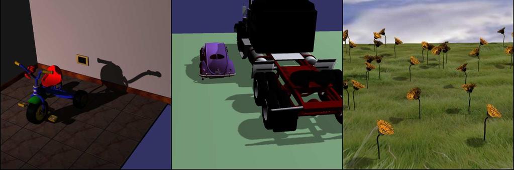
5 1 Introduction and Overview Recent developments in graphics hardware have led to systems which provide very high polygon throughput combined with sophisticated lighting and shading models. However, improvements in image quality are still focusing on local properties, e.g. using per fragment phong lighting. For realistic images, which should provide accurate impressions of the world in 3D, one must also consider the computation of global effects. One of the most important effects in this category are of course good-looking shadows. Shadows make 3D computer graphics look better. Without them, scenes often feel unnatural and flat, and the relative depths of objects in the scene can be very unclear. If you ve used OpenGL or Direct3D, you know that lights in these APIs do not automatically cast shadows. An example is shown in Figure 1. On the first image there is no shadows, making it very hard to determine whether the ball is on the ground or if it is floating above the ground. This is, on the other hand, easily determined on the following images, where shadows are shown. Figure1. Spatial Relationship. Left: it is hard to determine whether the ball is on the ground or floating on the air. Middle and Right: this is easily determined due to the shadows cast by the ball. There are lots of ways to compute shadows. The trouble with rendering high quality shadows is that they require a visibility test for each light source at each rasterized fragment. For ray tracers, adding an extra visibility test is trivial, but for rasterizers, it is not. Fortunately, there are a number of common cases where the light visibility test can be efficiently performed by a rasterizer. In the field of real-time and interactive rendering, there are only a few widely used algorithms. Casting shadows onto large receiver polygons is mostly done using projected geometry, whereas more complex receivers can only be handled using the shadow volume approach. These two methods have in common that they still require CPU resources to compute geometry and may generate a large amount of additional polygons that have to be pushed down the graphics pipeline. The main benefit of these algorithms is that all computations are done in object space which usually results in highly accurate shadows. Even if these techniques are capable of producing high-quality shadows, they are not suited for real-time applications, due to their object based computations, such as video games. They are usually used to produce shadows for static scenes or to compute shadows for large receiver planes, caused by only a few occluder objects. Another class of algorithms is based on the shadow mapping or depth mapping algorithm. These methods operate in image space which means that they rely on a sampling scheme to process the scene geometry. The shadow mapping algorithm can be used to compute shadows for arbitrary receiver and occluder geometry. Since sampling is the fundamental principal of all rasterization-based graphics architectures, shadow mapping is the first choice for realtime rendering. However, sampling methods all suffer from undersampling artifacts when it comes to higher frequency parts and the same for the shadow mapping algorithm. Sampling problems occur during the generation phase as well as when performing the actual shadow test. The first can be solved by increasing the image resolution and by using stochastic sampling instead of sampling at regular grid points. In order to resolve sampling artifacts during the shadow test, Reeves proposes a filtering method called percentage closer filtering which will be described later in more details. 4
6 2 Shadow Mapping Shadow mapping is an image-based shadowing technique developed by Lance Williams in It is particularly amenable to hardware implementation because it makes use of existing hardware functionality texturing and depth buffering. The only extra burden it places on hardware is the need to perform a high-precision scalar comparison for each texel fetched from the depth texture. Shadow mapping is also attractive to application programmers because it is very easy to use, and unlike stenciled shadow volumes, it requires no additional geometry processing. 2.1 Description The idea of the traditional shadow mapping consists of two steps. The first step serves the purpose of generating an image that contains depth information of the front-most pixel, seen by the light source. In computer graphics parlance, such an image is called a depth texture or shadow map. Such a depth texture is generating by setting up a camera with the position, direction, and view properties of the light source and rendering the scene. In the second pass, the scene is rendered once again from the actual camera point of view, but with the depth texture projected down from the light onto the scene using standard projective texture mapping. At each pixel, the depth sample (from the projected depth texture) is compared with fragment s distance from the light. If the latter is great, the pixel is not the closest surface to the light source. This means that the fragment is shadowed, and that it should not receive light during shading. Figure 2 illustrates the shadow mapping comparison. On the left panel of the figure, the point that is being shaded is in shadow, because the point s depth is greater than the depth that is recorded in the depth texture. In contrast, the right panel of the figure shows a case where are the point has the same depth as the recorded value in the depth texture. This means that there isn t any object between the point and the light source, so the point is lit (not in shadow). Figure2. The Shadow Mapping Depth Comparison. Left: the point that is being shaded is in shadow. Right: the point that is being shaded is not in the shadow. 5


7 2.2 First Pass First of all, the scene is rendered from the light s point of view. This is done by setting the camera view to the light view by the transformation shown in Figure 3. Figure3. Transformation from world space into light space. Next, the scene is rendered. Optimization is performed in this stage: instead of full rendering (color buffer and depth buffer), only rendering of the depth buffer into the depth texture is done using ARB_depth_texture, which defines a texture internal format for GL_DEPTH_COMPONENT, complete with various bits-per-texel choices. It usually takes about half the time that a full rendering takes. Furthermore, it is important that the viewport is only the size of the depth texture. Figure 4 illustrates a scene rendered from eye s point of view, light s point of view and the depth buffer of a scene rendered from the light s point of view. Figure4. Depth texture rendering. Left: the scene is rendered from the eye s point of view. Middle: the scene from the light s point of view. Right: the depth buffer from the light s point of view. 6

8 It is important that the near and far planes are located very precisely because the depth buffer has a limited precision. It is done by minimizing the distance between the near and the far planes by calculating the optimal near and far plane values which cover all the scene objects. This is done by calculating the bounding sphere of the whole scene and setting the near plane to be in a distance from the light source to the center of the scene minus radius of the scene, and the far plane to be in a distance from the light source to the center of the scene plus radius of the scene. This minimizes errors while comparing the depth values. Figure 5 illustrates how the settings of the near and far plane can affect the depth texture. In addition, the field of view of the light frustum is calculated in such a way that only the part of the scene which is seen by the eye is included. The geometrical solution is to calculate the convex hull of the eye frustum, and then set the light field of view to include the convex hull of the eye frustum. Figure5. Near and far plane settings. Left: the optimal near and far plane settings have been applied. It is seen that the contrast of the depth texture is large. Objects being close to the light source are nearly black. Right: the near and far plane not are optimized, the contrast of the depth texture degrades resulting in a less accuracy. The depth buffer needs to be copied into a depth texture. For a better performance, instead of rendering the scene into depth buffer and then copying it into the depth texture, rendering into depth texture is performed using fragment buffer object. 7

9 2.3 Projective Texture Mapping Projective texture mapping is a method of texture mapping that allows the texture image to be projected onto the scene as if by a slide projector. Figure 6 illustrates some example screen shots available in the NVIDIA OpenGL SDK. Figure6. Texture projected onto the scene Homogeneous Texture Coordinates Projective texture mapping is useful in a variety of lighting techniques, including shadow mapping. Projective texture mapping refers both to the way texture coordinates are assigned to vertices, and the way they are computed during rasterization of primitives. When performing projective texture mapping, we use homogeneous texture coordinates, or coordinates in projective space. When performing non-projective texture mapping, we use real texture coordinates, or coordinates in real space. For projective 2D texture mapping, the 3-component homogeneous coordinate vector (s, t, q) is interpolated over the primitive and then at each fragment, the interpolated homogeneous coordinates are projected to a real 2D texture coordinate, (s/q, t/q), to index into the texture image. For nonprojective 2D texture mapping, the 2-component real coordinate vector (s, t) is interpolated over the primitive and used directly to index into the texture image Texture Projector Consider that the texture is being projected onto the scene by a slide projector. This projector has most of the same properties that cameras have it has a viewing transform that transforms world space coordinate into projector space, and it has a projection transform that maps the projector space view volume to clip coordinates. Figure 7 illustrates the difference in transformations for a conventional camera vs. those for a projector. On the left image there is a sequence of transformations in the conventional pipeline, and on the right image there is a sequence of transformations for a projector. 8
10 Figure7. Difference in transformations for camera vs. projector. Left: a camera transformations pipeline. Right: a projector transformations pipeline Texture Coordinates Generation Using automatic texture coordinate generation texgen it is possible to transform the homogeneous texture coordinates (s, t, r, q) using the following matrix: 1. Multiply by the model view matrix. This applies any necessary model view transformations to the vertices. The model view matrix needs to be applied regardless of whether or not you are using projective texture mapping. 2. Multiply by the projector view matrix. This rotates and translates the vertices to the projector eye coordinates. 3. Multiply by projector projection matrix. This defines the projector s frustum, including its field of view and aspect ratio. In the case of shadow mapping the depth texture is projected from the light, so the projection view and projection matrixes are the light s one. 4. Scale and bias the results. Following steps 1 to 3, the transformed vertex values range from (-1) to 1. However, textures are indexed from 0 to 1, so the results have to be mapped to this range. This is done by multiplying the x, y and z components of the results by ½ and then adding ½. A single matrix multiplication accomplishes this mapping. 9

11 2.3.4 Reverse Projection Unlike a real projector, the math of projective texture mapping actually produces a dual projection. One along the projector s view direction, and another in the opposite direction. Figure 8 illustrates the reverse projective texture mapping effect. This problem is solved by comparing the value of q, cause the sign of q becomes negative behind the projector, which inverts the texture image in the reverse projection. Figure8. Reverse projective texture mapping: Produces a reverse projection as well. 10
12 2.4 Second Pass Next, the scene is rendered from the eye s point of view, but with the depth texture projected down from the light onto the scene using standard projective texture mapping. At each pixel, the depth sample (from the projected depth texture in (s/q, t/q)) is compared with the fragment s distance from the light that is r/q. If the latter is bigger (r/q > texture[s/q, t/q]), the pixel is not the closest surface to the light source. This means that the fragment is shadowed, and that it should not receive light during shading. If r/q texture[s/q, t/q], then the pixel is the closest surface to the light source. This means that the fragment is lit (not in shadow), and that it should receive light during shading. Figure 9 illustrates the whole process. Figure9. Shadow mapping: The whole process. 11

13 3 Light Types The simple implementation of shadow mapping only supports spot and directional lights. This is due to the fact that a single shadow mapping cannot encompass the entire hemisphere around itself. Cube mapping could be used to allow point light sources, however this would require up to six depth textures and therefore six renderings of the scene, decreasing the speed of the algorithm considerably. Directional lights are implemented by setting up the light source far away from the scene accordingly to its direction. 4 Self-Shadowing Artifacts The main problem when using shadow mapping is the limitation in resolution and precision of the depth texture. One artifact is self-shadowing which can be seen in figure 10. The cause is the resampling which take place when eye space pixel coordinates are transformed into light space to get the respective depth texture samples. Ideally, a surface point in eye space should map to the same surface point in the light coordinate system. Unfortunately, it is very likely that the result is slightly incorrect, due to machine rounding errors during the transformation of point from eye space into light space. The object might shadow itself, even if it is a lit part. Figure10. The effect of self-shadowing. Left: an error in depth comparison. Right: right depth comparison performed. To resolve this problem, a small bias is added to the depth texture values used in the comparison. This can be done using glpolygonoffset(factor, units), which offsets the depth value by an amount equal to: offset = factor*dz + units*r where DZ is the polygons slope and R is the smallest value guaranteed to produce a resolvable offset for the given implementation. The result of this can be seen in Figure 11. If the offset is too low, shadowing artifacts will appear. If the offset is too high, the shadow will move away from the object giving the impression that it is floating in case when the object is not. Finding the correct value is a challenging task which is highly scene dependant. 12

14 Figure11. The effect of biasing. Left: a good scene, which rendered with right polygon offset. Middle: no offset is used which results in many falsely shaded areas. Right: too high offset is used which results in moving shadows away. Another technique would be to render only back-facing polygons into the depth texture. Figure 12 illustrates the front-face culling process. This would result in the depth value when seen from the camera clearly being smaller than the corresponding depth texture value, thereby avoiding the biasing problem. This would, however, require the objects to be closed meshes, since false shadowing would otherwise occur, thereby loosing shadow mapping ability to calculate shadows independent of geometry. Figure12. Front-face culling. There is no point in rendering the polygons a, b into the depth texture cause only c, d cast shadow on objects. So polygons a, b are culled, and only polygons c, d are rendered into the depth texture. 13
 to smooth the edges.")
15 5 Filtering Although biasing errors are now minimized, there is still the problem of aliasing. Averaging depth values does not work. One way to reduce this problem is to use a filtering mechanism called percentage closer filtering (PCF) to smooth the edges. Instead of just comparing the depth value to the closest depth texture value, it is compared against a number of the closest values averaging the result. When shading each pixel in the eye view, PCF returns a value that indicates the amount of shadowing at each shaded point replacing the traditional depth comparison of ordinary shadow mapping. Figure 13 illustrates how percentage closer filtering (PCF) works. Basically, PCF works by reversing the order of filtering and comparing. Instead of first filtering the texture image over some specific region and using the resulting value for further processing, PCF performs the comparison step. PCF is based on the observation that as the size of PCF kernel increases, the resulting shadows become softer. The challenge is to vary the filter size intelligently to achieve the correct degree of softness. When linear filtering is performed on the depth texture, the graphics card hardware applies the 2x2 PCF. Figure 14 illustrates the PCF influence. Figure13. Percentage Closer Filtering (PCF). Left: the pixel to be shaded. Top: the shaded pixel without PCF. Bottom: the shaded pixel with 2x2 PCF kernel. 14


16 Figure14. Percentage Closer Filtering (PCF). Left: a shadow with no PCF. Middle: a shadow with 3x3 PCF kernel. Right: a shadow with 4x4 PCF kernel. Top: the nearest filter is used. Bottom: the linear filter is used. 6 Ambient Shadows Rendering the depth texture with standard OpenGL does not look very good. The shadow is completely black. To alleviate this problem, ambient shadows coefficient is used that determines the fraction of light that is actually blocked. Objects tend to look too flat if all the light is blocked because there is no shading variations to reveal surface curvature. Lightening the shadows also keeps them from being too "harsh". Figure 15 illustrates the ambient shadows influence. Figure15. The ambient shadowing. Left: the ambient shadows coefficient is set to 0.0 it is absolutely black. Middle: the ambient shadows coefficient is set to 0.4 still evidence of curvature in shadowed regions. Right: the ambient shadows coefficient is set to 0.8 more details of the scene is seen. 15
17 7 Projective Texture As projective texture mapping is part of the shadow mapping process, we can use it for projecting texture on the scene. Where there is a shadow (behind occluders), projective texture is not applied, which is true for a real projector. Figure 16 illustrates the result of projected texture and shadows both applied on the scene using different projective texture brightness. Figure16. Projective texture mapping. Left: a scene with projected texture with brightness 0.2. Middle: a scene with projected texture with brightness 0.5. Right: a scene with projected texture with brightness
.")
18 8 Implementation The whole project is implemented using OpenSceneGraph library (see section 8.1.1) and shaders mechanism in both CG and GLSL languages. The first and second passes is done in OpenSceneGraph, while the shadow calculations is done in fragment program without unnecessary use of vertex program (see section ). The core of shadows is packed into dll, which can be used by OpenSceneGraph users OpenSceneGraph Library Background The OpenSceneGraph is an open source, cross platform graphics toolkit for the development of high performance graphics applications such as flight simulators, games, virtual reality and scientific visualization. Based around the concept of a scene graph, it provides an object oriented framework on top of OpenGL freeing the developer from implementing and optimizing low level graphics calls, and provides many additional utilities for rapid development of graphics applications Shaders Mechanism Background In August 1999, the first Graphics Processing Unit (GPU) has been introduced in PC industry. A GPU is a 3D processor that integrates the whole graphics pipeline in one chip. Graphics processors free the PCs processor from all 3D specific calculations so the normal CPUs can save performance for application specific computations. Latest features of graphics cards are enabled by their drivers which establish the communications between the PC and application. These features work on all APIs which support them. If the underlying hardware does not support a feature, then the driver emulates it and it runs on the host CPU. An example of such a new technology is the programmable interfaces to graphics hardware. It allows the user to replace fixed wired functionality on the graphics chip with user defined programs. At the moment there are three stages in the graphics pipeline that can be accessed by user defined programs: the geometry of vertex processing unit, the texturing unit and the fragment processing unit Vertex Programs Vertex programs are small assembly like programs written by the programmer. Once a vertex program is enabled, the fixed wired vertex processing unit is bypassed and substituted by the vertex program. Figure 17 illustrates this bypass. The advantage of vertex program is that it is much faster than software implementation. Figure17. Bypassed vertex processing unit. 17
19 Vertex programs are written in a SIMD instruction set which is strictly sequential. This means there is no instruction to return before the end and there are also no conditional flow controls available. Note that vertex programs have many advantages due to their flexibility and speed, but they also require the user to implement all basic functionality by himself Texture Fetching Traditional texture fetching retrieves a value from a texture addresses by certain texture coordinates. For applying the projective texture sampling a different command is used in which the corresponding homogeneous textures coordinate s/q and t/q are used to access the texture and read the value at this position. In addition, when the above projective texture sampling is done on a depth texture, the hardware also makes the comparison Fragment Programs Fragment programs operate on pixel information. They bypass the part of the graphics pipe which deals with constructing the final pixel color. Fragment programs have the same advantages as vertex programs have, and suffer from the same disadvantages as vertex programs do. 8.2 API Shadows: Enable enables/disables the shadow UseShader defines which of the shader languages will be used (CG, GLSL or no shader) SetAntialiasingMode sets the antialiasing mode (2x2, 3x3, 4x4 or no antialiasing) SupportHardwareAntialiasing enables/disables hardware antialiasing support SetLightDirection sets the light source to be directional light source SetFrustum sets the user shadows frustum CalculateFrustumAutomatically enables automatically frustum calculations SetAmbientShadow sets the ambient shadow coefficient SetDefaultBias sets the default bias factor to 1.1 and bias units to 4.0 SetBias sets the user bias factor and units CullFaces enables/disables the front faces culling ProjectiveTexture: EnableProjectiveTexture enables/disables the projective texture SetProjectiveTextureFileName sets the projective texture from file SetProjectiveTextureBrightness sets the projective texture brightness 18
20 8.3 Improvements and Optimizations In the first pass instead of full rendering, only rendering into depth buffer is done. In the first pass instead of rendering the scene into depth buffer and then copying it into the depth texture, rendering into the depth texture is performed using framebuffer object. Depth texture size can be defined by the user. Light frustum is efficiently calculated each frame. Reverse projection is eliminated. Spot and directional lights, biasing, antialiasing and hardware antialiasing, ambient shadows, projected texture, CG and GLSL shading languages are supported. 9 Hardware Requirements Hardware accelerated shadow mapping is available today starting on NVIDIA GeForce 3 GPUs. It is exposed in OpenGL through the SGIX_shadow and SGIX_depth_texture extensions, and in Direct3D 8 through a special texture format. Antialiased shadow mapping is available starting on NVIDIA GeForce 4 GPUs using OpenGL through the ARB_shadow and ARB_depth_texture extensions. Framebuffer object is available starting on NVIDIA GeForce 6 GPUs using OpenGL through the EXT_framebuffer_object extension. The results described in section 11 tested on the following cards: NVIDIA GeForce 5200, 5900, 5950, 6600, 6800, Summary Shadow mapping is capable of computing shadow for any arbitrary geometry and best suited for realtime and interactive applications, because it can be completely ported to graphics hardware. The shadow mapping generation process growth linearly in time with the number of primitives. The total additional time is therefore roughly twice the time as without shadows. No lighting, shading and texture computation is required, while the depth texture is rendered, and only a few additional transformation calculations are needed. In contrast to these advantages, shadow mapping suffers from aliasing artifacts and insufficient depth texture resolution, leading to coarse shadows. Various techniques such as percentage closer filtering or adding a certain bias can be used to solve aliasing artifacts. Still, the limitation of the field of view and the waste of valuable depth texture space often remain an unsolved problem. 19


21 11 Results Figure18. Resulting images. 20
22 12 Future Work This project implements a traditional shadow mapping algorithm, which is definitely can be improved. The common improvement for shadow mapping is perspective shadow mapping. This approach adapts the depth texture resolution according to the camera setup, and generates a single perspective depth texture by using non-uniform parameterization. This method exploits graphics hardware and reduces shadow mapping aliasing significantly, because the area of projected depth texture pixels in post-perspective space is almost equivalent to the area of eye view pixels. Perspective shadow mapping provide nearby objects high resolution, while more distant objects are rendered with decreasing resolution. Aliasing artifacts and jagged edges occur on shadow boundaries. Thus, to obtain high-quality shadows the corresponding depth texture does not need an overall high resolution, but only requires high resolution on shadow boundaries. To determine these regions the adaptive shadow mapping algorithm evaluates how much depth texture pixels contribute to the total image quality, and refines the depth texture in such a way that it creates new higher resolution pieces if needed. On shadow boundaries, the depth texture resolution should be at least the same as the resolution in eye space to avoid coarse shadow. Traditional shadow mapping is only useful in conjunction with a perspective projection using a reasonable filed of view (FOV). Therefore, shadow mapping for hemispherical or omnidirectional light sources fails. Sphere mapping was the first environment mapping technique supported by consumer level hardware. This method generates a 2D texture image in the following way. In a first step a perfectly mirroring sphere is centered around the objects of interest. The appearance of the surrounding environment is then derived from an orthographic camera facing this ball. The disadvantage of this mapping is that pixels along the perimeter of the flattened ball get extremely distorted. Paraboloid mapping is another mapping similar to sphere mapping. Using this mapping, the 2D texture image is obtained by the view of an orthographic camera facing a perfectly mirroring paraboloid instead of a sphere. In contrast to the spherical parameterizations, this method does not introduce that much artifacts due to a better sampling rate. For omnidirectional lights, two paraboloids are simply attached back to back. Real life light sources are not point light sources, they cover a given area in space and therefore the transition of the shadow boundaries is usually more smooth. Soft shadows take care of this smoothing. Till now we discussed about shadows generation for one single light source. A number of lights can be added to the scene, which gives it more realistic quality. 21
23 13 References [1] Lance Williams, "Casting Curved Shadows on Curved Surfaces", SIGGRAPH 78. [2] William Reeves, David Salesin, "Rendering Antialiased Shadows With Depth Maps". SIGGRAPH 87. [3] Mark Segal, Fast Shadows and Lighting Effects Using Texture Mapping. SIGGRAPH 92. [4] Thomas Annen, Advanced Shadow Map Parameterization. Diploma thesis in Computer Science. [5] Simon Kozlov, Perspective Shadow Maps: Care and Feeding. GPU Gems. [6] Gary King, Perspective Shadow Maps. NVidia. [7] Randima Fernando, Percentage-Closer Soft Shadows. NVidia. [8] Cass Everitt, Projective Texture Mapping. NVidia. [9] Cass Everitt, Ashu Rege, Cem Ceneboyan, Hardware Shadow Mapping. NVidia. [10] Joen Sindholt, A Comparison of Shadow Algorithms. [11] GPU Gems. NVidia. [12] CG Tutorials. NVidia. 22
Computer Graphics Shadow Algorithms
 Computer Graphics Shadow Algorithms Computer Graphics Computer Science Department University of Freiburg WS 11 Outline introduction projection shadows shadow maps shadow volumes conclusion Motivation shadows
Computergrafik. Matthias Zwicker. Herbst 2010
 Computergrafik Matthias Zwicker Universität Bern Herbst 2010 Today Bump mapping Shadows Shadow mapping Shadow mapping in OpenGL Bump mapping Surface detail is often the result of small perturbations in
CMSC427 Advanced shading getting global illumination by local methods. Credit: slides Prof. Zwicker
 CMSC427 Advanced shading getting global illumination by local methods Credit: slides Prof. Zwicker Topics Shadows Environment maps Reflection mapping Irradiance environment maps Ambient occlusion Reflection
Pipeline Operations. CS 4620 Lecture 10
 Pipeline Operations CS 4620 Lecture 10 2008 Steve Marschner 1 Hidden surface elimination Goal is to figure out which color to make the pixels based on what s in front of what. Hidden surface elimination
Lecture 17: Shadows. Projects. Why Shadows? Shadows. Using the Shadow Map. Shadow Maps. Proposals due today. I will mail out comments
 Projects Lecture 17: Shadows Proposals due today I will mail out comments Fall 2004 Kavita Bala Computer Science Cornell University Grading HW 1: will email comments asap Why Shadows? Crucial for spatial
Practical Shadow Mapping
 Practical Shadow Mapping Stefan Brabec Thomas Annen Hans-Peter Seidel Max-Planck-Institut für Informatik Saarbrücken, Germany Abstract In this paper we propose several methods that can greatly improve
Pipeline Operations. CS 4620 Lecture Steve Marschner. Cornell CS4620 Spring 2018 Lecture 11
 Pipeline Operations CS 4620 Lecture 11 1 Pipeline you are here APPLICATION COMMAND STREAM 3D transformations; shading VERTEX PROCESSING TRANSFORMED GEOMETRY conversion of primitives to pixels RASTERIZATION
Shadow Mapping for Hemispherical and Omnidirectional Light Sources
 Shadow Mapping for Hemispherical and Omnidirectional Light Sources Abstract Stefan Brabec Thomas Annen Hans-Peter Seidel Computer Graphics Group Max-Planck-Institut für Infomatik Stuhlsatzenhausweg 85,
Pipeline Operations. CS 4620 Lecture 14
 Pipeline Operations CS 4620 Lecture 14 2014 Steve Marschner 1 Pipeline you are here APPLICATION COMMAND STREAM 3D transformations; shading VERTEX PROCESSING TRANSFORMED GEOMETRY conversion of primitives
Rasterization Overview
 Rendering Overview The process of generating an image given a virtual camera objects light sources Various techniques rasterization (topic of this course) raytracing (topic of the course Advanced Computer
Multi-View Soft Shadows. Louis Bavoil
 Multi-View Soft Shadows Louis Bavoil lbavoil@nvidia.com Document Change History Version Date Responsible Reason for Change 1.0 March 16, 2011 Louis Bavoil Initial release Overview The Multi-View Soft Shadows
TSBK03 Screen-Space Ambient Occlusion
 TSBK03 Screen-Space Ambient Occlusion Joakim Gebart, Jimmy Liikala December 15, 2013 Contents 1 Abstract 1 2 History 2 2.1 Crysis method..................................... 2 3 Chosen method 2 3.1 Algorithm
Last Time. Why are Shadows Important? Today. Graphics Pipeline. Clipping. Rasterization. Why are Shadows Important?
 Last Time Modeling Transformations Illumination (Shading) Real-Time Shadows Viewing Transformation (Perspective / Orthographic) Clipping Projection (to Screen Space) Graphics Pipeline Clipping Rasterization
graphics pipeline computer graphics graphics pipeline 2009 fabio pellacini 1
 graphics pipeline computer graphics graphics pipeline 2009 fabio pellacini 1 graphics pipeline sequence of operations to generate an image using object-order processing primitives processed one-at-a-time
CHAPTER 1 Graphics Systems and Models 3
 ?????? 1 CHAPTER 1 Graphics Systems and Models 3 1.1 Applications of Computer Graphics 4 1.1.1 Display of Information............. 4 1.1.2 Design.................... 5 1.1.3 Simulation and Animation...........
graphics pipeline computer graphics graphics pipeline 2009 fabio pellacini 1
 graphics pipeline computer graphics graphics pipeline 2009 fabio pellacini 1 graphics pipeline sequence of operations to generate an image using object-order processing primitives processed one-at-a-time
For Intuition about Scene Lighting. Today. Limitations of Planar Shadows. Cast Shadows on Planar Surfaces. Shadow/View Duality.
 Last Time Modeling Transformations Illumination (Shading) Real-Time Shadows Viewing Transformation (Perspective / Orthographic) Clipping Projection (to Screen Space) Graphics Pipeline Clipping Rasterization
What for? Shadows tell us about the relative locations. Vienna University of Technology 2
 Shadows What for? Shadows tell us about the relative locations and motions of objects Vienna University of Technology 2 What for? Shadows tell us about the relative locations and motions of objects And
Deferred Rendering Due: Wednesday November 15 at 10pm
 CMSC 23700 Autumn 2017 Introduction to Computer Graphics Project 4 November 2, 2017 Deferred Rendering Due: Wednesday November 15 at 10pm 1 Summary This assignment uses the same application architecture
The Traditional Graphics Pipeline
 Last Time? The Traditional Graphics Pipeline Participating Media Measuring BRDFs 3D Digitizing & Scattering BSSRDFs Monte Carlo Simulation Dipole Approximation Today Ray Casting / Tracing Advantages? Ray
Orthogonal Projection Matrices. Angel and Shreiner: Interactive Computer Graphics 7E Addison-Wesley 2015
 Orthogonal Projection Matrices 1 Objectives Derive the projection matrices used for standard orthogonal projections Introduce oblique projections Introduce projection normalization 2 Normalization Rather
Last Time. Reading for Today: Graphics Pipeline. Clipping. Rasterization
 Last Time Modeling Transformations Illumination (Shading) Real-Time Shadows Viewing Transformation (Perspective / Orthographic) Clipping Projection (to Screen Space) Scan Conversion (Rasterization) Visibility
Real-Time Shadows. Last Time? Today. Why are Shadows Important? Shadows as a Depth Cue. For Intuition about Scene Lighting
 Last Time? Real-Time Shadows Today Why are Shadows Important? Shadows & Soft Shadows in Ray Tracing Planar Shadows Projective Texture Shadows Shadow Maps Shadow Volumes Why are Shadows Important? Depth
Dual-Paraboloid Shadow Mapping. A paper by Stefan Brabec, Thomas Annen, Hans-Peter Seidel Presented By Patrick Wouterse, Selmar Kok
 A paper by Stefan Brabec, Thomas Annen, Hans-Peter Seidel Presented By Patrick Wouterse, Selmar Kok Introduction and Background An improved perspective shadow mapping technique Less memory and render passes
Shadow Techniques. Sim Dietrich NVIDIA Corporation
 Shadow Techniques Sim Dietrich NVIDIA Corporation sim.dietrich@nvidia.com Lighting & Shadows The shadowing solution you choose can greatly influence the engine decisions you make This talk will outline
Shadows in the graphics pipeline
 Shadows in the graphics pipeline Steve Marschner Cornell University CS 569 Spring 2008, 19 February There are a number of visual cues that help let the viewer know about the 3D relationships between objects
High-quality Shadows with Improved Paraboloid Mapping
 High-quality Shadows with Improved Paraboloid Mapping Juraj Vanek, Jan Navrátil, Adam Herout, and Pavel Zemčík Brno University of Technology, Faculty of Information Technology, Czech Republic http://www.fit.vutbr.cz
3D Rasterization II COS 426
 3D Rasterization II COS 426 3D Rendering Pipeline (for direct illumination) 3D Primitives Modeling Transformation Lighting Viewing Transformation Projection Transformation Clipping Viewport Transformation
Screen Space Ambient Occlusion TSBK03: Advanced Game Programming
 Screen Space Ambient Occlusion TSBK03: Advanced Game Programming August Nam-Ki Ek, Oscar Johnson and Ramin Assadi March 5, 2015 This project report discusses our approach of implementing Screen Space Ambient
CS 354R: Computer Game Technology
 CS 354R: Computer Game Technology Texture and Environment Maps Fall 2018 Texture Mapping Problem: colors, normals, etc. are only specified at vertices How do we add detail between vertices without incurring
The Traditional Graphics Pipeline
 Last Time? The Traditional Graphics Pipeline Reading for Today A Practical Model for Subsurface Light Transport, Jensen, Marschner, Levoy, & Hanrahan, SIGGRAPH 2001 Participating Media Measuring BRDFs
Programming Graphics Hardware
 Tutorial 5 Programming Graphics Hardware Randy Fernando, Mark Harris, Matthias Wloka, Cyril Zeller Overview of the Tutorial: Morning 8:30 9:30 10:15 10:45 Introduction to the Hardware Graphics Pipeline
Shadow Mapping. Render Scene and Access the Depth Texture. What is Projective Texturing? About Projective Texturing (1) About Projective Texturing (3)
 About Projective Texturing (3)") Render Scene and Access the Depth Texture Shadow Mapping Cass Everitt NVIDIA Corporation cass@nvidia.com Realizing the theory in practice Fragment s light position can be generated using eye-linear texture
Render Scene and Access the Depth Texture Shadow Mapping Cass Everitt NVIDIA Corporation cass@nvidia.com Realizing the theory in practice Fragment s light position can be generated using eye-linear texture
Real-Time Shadows. MIT EECS 6.837, Durand and Cutler
 Real-Time Shadows Last Time? The graphics pipeline Clipping & rasterization of polygons Visibility the depth buffer (z-buffer) Schedule Quiz 2: Thursday November 20 th, in class (two weeks from Thursday)
The Traditional Graphics Pipeline
 Final Projects Proposals due Thursday 4/8 Proposed project summary At least 3 related papers (read & summarized) Description of series of test cases Timeline & initial task assignment The Traditional Graphics
Real-Time Shadows. Last Time? Textures can Alias. Schedule. Questions? Quiz 1: Tuesday October 26 th, in class (1 week from today!
 Last Time? Real-Time Shadows Perspective-Correct Interpolation Texture Coordinates Procedural Solid Textures Other Mapping Bump Displacement Environment Lighting Textures can Alias Aliasing is the under-sampling
S U N G - E U I YO O N, K A I S T R E N D E R I N G F R E E LY A VA I L A B L E O N T H E I N T E R N E T
 S U N G - E U I YO O N, K A I S T R E N D E R I N G F R E E LY A VA I L A B L E O N T H E I N T E R N E T Copyright 2018 Sung-eui Yoon, KAIST freely available on the internet http://sglab.kaist.ac.kr/~sungeui/render
Shadows. Real-Time Hard Shadows. Collected by Ronen Gvili. Most slides were taken from : Fredu Durand Stefan Brabec
 Shadows Real-Time Hard Shadows Collected by Ronen Gvili. Most slides were taken from : Fredu Durand Stefan Brabec Hard Shadows Planar (Projected) Shadows Shadow Maps Volume (Stencil) Shadows 1 Soft Shadows
Acknowledgement: Images and many slides from presentations by Mark J. Kilgard and other Nvidia folks, from slides on developer.nvidia.
 Shadows Acknowledgement: Images and many slides from presentations by Mark J. Kilgard and other Nvidia folks, from slides on developer.nvidia.com Practical & Robust Stenciled Shadow Volumes for Hardware-Accelerated
Mattan Erez. The University of Texas at Austin
 EE382V: Principles in Computer Architecture Parallelism and Locality Fall 2008 Lecture 10 The Graphics Processing Unit Mattan Erez The University of Texas at Austin Outline What is a GPU? Why should we
Chapter 10 Computation Culling with Explicit Early-Z and Dynamic Flow Control
 Chapter 10 Computation Culling with Explicit Early-Z and Dynamic Flow Control Pedro V. Sander ATI Research John R. Isidoro ATI Research Jason L. Mitchell ATI Research Introduction In last year s course,
PowerVR Hardware. Architecture Overview for Developers
 Public Imagination Technologies PowerVR Hardware Public. This publication contains proprietary information which is subject to change without notice and is supplied 'as is' without warranty of any kind.
Real-Time Shadows. Last Time? Schedule. Questions? Today. Why are Shadows Important?
 Last Time? Real-Time Shadows The graphics pipeline Clipping & rasterization of polygons Visibility the depth buffer (z-buffer) Schedule Questions? Quiz 2: Thursday November 2 th, in class (two weeks from
The Rasterization Pipeline
 Lecture 5: The Rasterization Pipeline Computer Graphics and Imaging UC Berkeley CS184/284A, Spring 2016 What We ve Covered So Far z x y z x y (0, 0) (w, h) Position objects and the camera in the world
Overview. A real-time shadow approach for an Augmented Reality application using shadow volumes. Augmented Reality.
 Overview A real-time shadow approach for an Augmented Reality application using shadow volumes Introduction of Concepts Standard Stenciled Shadow Volumes Method Proposed Approach in AR Application Experimental
Texture Mapping II. Light maps Environment Maps Projective Textures Bump Maps Displacement Maps Solid Textures Mipmaps Shadows 1. 7.
 Texture Mapping II Light maps Environment Maps Projective Textures Bump Maps Displacement Maps Solid Textures Mipmaps Shadows 1 Light Maps Simulates the effect of a local light source + = Can be pre-computed
Real-Time Shadows. Computer Graphics. MIT EECS Durand 1
 Real-Time Shadows Computer Graphics MIT EECS 6.837 Durand 1 Why are Shadows Important? Depth cue Scene Lighting Realism Contact points 2 Shadows as a Depth Cue source unknown. All rights reserved. This
Spring 2009 Prof. Hyesoon Kim
 Spring 2009 Prof. Hyesoon Kim Application Geometry Rasterizer CPU Each stage cane be also pipelined The slowest of the pipeline stage determines the rendering speed. Frames per second (fps) Executes on
Rendering Objects. Need to transform all geometry then
 Intro to OpenGL Rendering Objects Object has internal geometry (Model) Object relative to other objects (World) Object relative to camera (View) Object relative to screen (Projection) Need to transform
Shadows. Shadows. Spatial relationship between objects. Shadows as depth cue. Spatial relationship between objects
 Shadows Thanks to: Frédo Durand and Seth Teller MIT Shadows Realism Depth cue 1 2 Shadows as depth cue Spatial relationship between objects 3 Michael McCool Univ of Waterloo 4 Spatial relationship between
Real-Time Rendering of a Scene With Many Pedestrians
 2015 http://excel.fit.vutbr.cz Real-Time Rendering of a Scene With Many Pedestrians Va clav Pfudl Abstract The aim of this text was to describe implementation of software that would be able to simulate
Point Cloud Filtering using Ray Casting by Eric Jensen 2012 The Basic Methodology
 Point Cloud Filtering using Ray Casting by Eric Jensen 01 The Basic Methodology Ray tracing in standard graphics study is a method of following the path of a photon from the light source to the camera,
Rendering. Converting a 3D scene to a 2D image. Camera. Light. Rendering. View Plane
 Rendering Pipeline Rendering Converting a 3D scene to a 2D image Rendering Light Camera 3D Model View Plane Rendering Converting a 3D scene to a 2D image Basic rendering tasks: Modeling: creating the world
C P S C 314 S H A D E R S, O P E N G L, & J S RENDERING PIPELINE. Mikhail Bessmeltsev
 C P S C 314 S H A D E R S, O P E N G L, & J S RENDERING PIPELINE UGRAD.CS.UBC.C A/~CS314 Mikhail Bessmeltsev 1 WHAT IS RENDERING? Generating image from a 3D scene 2 WHAT IS RENDERING? Generating image
Module Contact: Dr Stephen Laycock, CMP Copyright of the University of East Anglia Version 1
 UNIVERSITY OF EAST ANGLIA School of Computing Sciences Main Series PG Examination 2013-14 COMPUTER GAMES DEVELOPMENT CMPSME27 Time allowed: 2 hours Answer any THREE questions. (40 marks each) Notes are
Direct Rendering of Trimmed NURBS Surfaces
 Direct Rendering of Trimmed NURBS Surfaces Hardware Graphics Pipeline 2/ 81 Hardware Graphics Pipeline GPU Video Memory CPU Vertex Processor Raster Unit Fragment Processor Render Target Screen Extended
CS230 : Computer Graphics Lecture 4. Tamar Shinar Computer Science & Engineering UC Riverside
 CS230 : Computer Graphics Lecture 4 Tamar Shinar Computer Science & Engineering UC Riverside Shadows Shadows for each pixel do compute viewing ray if ( ray hits an object with t in [0, inf] ) then compute
CS451Real-time Rendering Pipeline
 1 CS451Real-time Rendering Pipeline JYH-MING LIEN DEPARTMENT OF COMPUTER SCIENCE GEORGE MASON UNIVERSITY Based on Tomas Akenine-Möller s lecture note You say that you render a 3D 2 scene, but what does
DEFERRED RENDERING STEFAN MÜLLER ARISONA, ETH ZURICH SMA/
 DEFERRED RENDERING STEFAN MÜLLER ARISONA, ETH ZURICH SMA/2013-11-04 DEFERRED RENDERING? CONTENTS 1. The traditional approach: Forward rendering 2. Deferred rendering (DR) overview 3. Example uses of DR:
Models and Architectures
 Models and Architectures Objectives Learn the basic design of a graphics system Introduce graphics pipeline architecture Examine software components for an interactive graphics system 1 Image Formation
Tutorial on GPU Programming #2. Joong-Youn Lee Supercomputing Center, KISTI
 Tutorial on GPU Programming #2 Joong-Youn Lee Supercomputing Center, KISTI Contents Graphics Pipeline Vertex Programming Fragment Programming Introduction to Cg Language Graphics Pipeline The process to
Robust Stencil Shadow Volumes. CEDEC 2001 Tokyo, Japan
 Robust Stencil Shadow Volumes CEDEC 2001 Tokyo, Japan Mark J. Kilgard Graphics Software Engineer NVIDIA Corporation 2 Games Begin to Embrace Robust Shadows 3 John Carmack s new Doom engine leads the way
Many rendering scenarios, such as battle scenes or urban environments, require rendering of large numbers of autonomous characters.
 1 2 Many rendering scenarios, such as battle scenes or urban environments, require rendering of large numbers of autonomous characters. Crowd rendering in large environments presents a number of challenges,
Hardware-driven visibility culling
 Hardware-driven visibility culling I. Introduction 20073114 김정현 The goal of the 3D graphics is to generate a realistic and accurate 3D image. To achieve this, it needs to process not only large amount
Adaptive Point Cloud Rendering
 1 Adaptive Point Cloud Rendering Project Plan Final Group: May13-11 Christopher Jeffers Eric Jensen Joel Rausch Client: Siemens PLM Software Client Contact: Michael Carter Adviser: Simanta Mitra 4/29/13
Applications of Explicit Early-Z Culling
 Applications of Explicit Early-Z Culling Jason L. Mitchell ATI Research Pedro V. Sander ATI Research Introduction In past years, in the SIGGRAPH Real-Time Shading course, we have covered the details of
Shadow Rendering EDA101 Advanced Shading and Rendering
 Shadow Rendering EDA101 Advanced Shading and Rendering 2006 Tomas Akenine-Möller 1 Why, oh why? (1) Shadows provide cues about spatial relationships among objects 2006 Tomas Akenine-Möller 2 Why, oh why?
Advanced Shading I: Shadow Rasterization Techniques
 Advanced Shading I: Shadow Rasterization Techniques Shadow Terminology umbra: light totally blocked penumbra: light partially blocked occluder: object blocking light Shadow Terminology umbra: light totally
CSE 167: Introduction to Computer Graphics Lecture #4: Vertex Transformation
 CSE 167: Introduction to Computer Graphics Lecture #4: Vertex Transformation Jürgen P. Schulze, Ph.D. University of California, San Diego Fall Quarter 2013 Announcements Project 2 due Friday, October 11
Spring 2011 Prof. Hyesoon Kim
 Spring 2011 Prof. Hyesoon Kim Application Geometry Rasterizer CPU Each stage cane be also pipelined The slowest of the pipeline stage determines the rendering speed. Frames per second (fps) Executes on
Topics and things to know about them:
 Practice Final CMSC 427 Distributed Tuesday, December 11, 2007 Review Session, Monday, December 17, 5:00pm, 4424 AV Williams Final: 10:30 AM Wednesday, December 19, 2007 General Guidelines: The final will
Introduction to Visualization and Computer Graphics
 Introduction to Visualization and Computer Graphics DH2320, Fall 2015 Prof. Dr. Tino Weinkauf Introduction to Visualization and Computer Graphics Visibility Shading 3D Rendering Geometric Model Color Perspective
03 RENDERING PART TWO
 03 RENDERING PART TWO WHAT WE HAVE SO FAR: GEOMETRY AFTER TRANSFORMATION AND SOME BASIC CLIPPING / CULLING TEXTURES AND MAPPING MATERIAL VISUALLY DISTINGUISHES 2 OBJECTS WITH IDENTICAL GEOMETRY FOR NOW,
TDA362/DIT223 Computer Graphics EXAM (Same exam for both CTH- and GU students)
") TDA362/DIT223 Computer Graphics EXAM (Same exam for both CTH- and GU students) Saturday, January 13 th, 2018, 08:30-12:30 Examiner Ulf Assarsson, tel. 031-772 1775 Permitted Technical Aids None, except
TDA362/DIT223 Computer Graphics EXAM (Same exam for both CTH- and GU students) Saturday, January 13 th, 2018, 08:30-12:30 Examiner Ulf Assarsson, tel. 031-772 1775 Permitted Technical Aids None, except
Interactive Computer Graphics A TOP-DOWN APPROACH WITH SHADER-BASED OPENGL
 International Edition Interactive Computer Graphics A TOP-DOWN APPROACH WITH SHADER-BASED OPENGL Sixth Edition Edward Angel Dave Shreiner Interactive Computer Graphics: A Top-Down Approach with Shader-Based
Soft shadows. Steve Marschner Cornell University CS 569 Spring 2008, 21 February
 Soft shadows Steve Marschner Cornell University CS 569 Spring 2008, 21 February Soft shadows are what we normally see in the real world. If you are near a bare halogen bulb, a stage spotlight, or other
CS 4620 Program 3: Pipeline
 CS 4620 Program 3: Pipeline out: Wednesday 14 October 2009 due: Friday 30 October 2009 1 Introduction In this assignment, you will implement several types of shading in a simple software graphics pipeline.
2D rendering takes a photo of the 2D scene with a virtual camera that selects an axis aligned rectangle from the scene. The photograph is placed into
 2D rendering takes a photo of the 2D scene with a virtual camera that selects an axis aligned rectangle from the scene. The photograph is placed into the viewport of the current application window. A pixel
Today. Texture mapping in OpenGL. Texture mapping. Basic shaders for texturing. Today. Computergrafik
 Computergrafik Today Basic shader for texture mapping Texture coordinate assignment Antialiasing Fancy textures Matthias Zwicker Universität Bern Herbst 2009 Texture mapping Glue textures (images) onto
Shadow Algorithms. CSE 781 Winter Han-Wei Shen
 Shadow Algorithms CSE 781 Winter 2010 Han-Wei Shen Why Shadows? Makes 3D Graphics more believable Provides additional cues for the shapes and relative positions of objects in 3D What is shadow? Shadow:
Scanline Rendering 2 1/42
 Scanline Rendering 2 1/42 Review 1. Set up a Camera the viewing frustum has near and far clipping planes 2. Create some Geometry made out of triangles 3. Place the geometry in the scene using Transforms
Shadows in Computer Graphics. by Björn Kühl im/ve University of Hamburg, Germany
 Shadows in Computer Graphics by Björn Kühl im/ve University of Hamburg, Germany Importance of Shadows Shadows provide cues to the position of objects casting and receiving shadows to the position of the
Computer Graphics I Lecture 11
 15-462 Computer Graphics I Lecture 11 Midterm Review Assignment 3 Movie Midterm Review Midterm Preview February 26, 2002 Frank Pfenning Carnegie Mellon University http://www.cs.cmu.edu/~fp/courses/graphics/
Computergrafik. Matthias Zwicker Universität Bern Herbst 2016
 Computergrafik Matthias Zwicker Universität Bern Herbst 2016 2 Today Basic shader for texture mapping Texture coordinate assignment Antialiasing Fancy textures 3 Texture mapping Glue textures (images)
VGP353 Week 2. Agenda: Assignment #1 due Introduce shadow maps. Differences / similarities with shadow textures Added benefits Potential problems
 VGP353 Week 2 Agenda: Assignment #1 due Introduce shadow maps Differences / similarities with shadow textures Added benefits Potential problems Shadow Textures Shadow textures have a number of faults:
GUERRILLA DEVELOP CONFERENCE JULY 07 BRIGHTON
 Deferred Rendering in Killzone 2 Michal Valient Senior Programmer, Guerrilla Talk Outline Forward & Deferred Rendering Overview G-Buffer Layout Shader Creation Deferred Rendering in Detail Rendering Passes
COMP environment mapping Mar. 12, r = 2n(n v) v
 v") Rendering mirror surfaces The next texture mapping method assumes we have a mirror surface, or at least a reflectance function that contains a mirror component. Examples might be a car window or hood,
Rendering mirror surfaces The next texture mapping method assumes we have a mirror surface, or at least a reflectance function that contains a mirror component. Examples might be a car window or hood,
1.2.3 The Graphics Hardware Pipeline
 Figure 1-3. The Graphics Hardware Pipeline 1.2.3 The Graphics Hardware Pipeline A pipeline is a sequence of stages operating in parallel and in a fixed order. Each stage receives its input from the prior
CS 130 Final. Fall 2015
 CS 130 Final Fall 2015 Name Student ID Signature You may not ask any questions during the test. If you believe that there is something wrong with a question, write down what you think the question is trying
BCC Sphere Transition
 BCC Sphere Transition The Sphere Transition shape models the source image onto a sphere. Unlike the Sphere filter, the Sphere Transition filter allows you to animate Perspective, which is useful in creating
CS 130 Exam I. Fall 2015
 S 3 Exam I Fall 25 Name Student ID Signature You may not ask any questions during the test. If you believe that there is something wrong with a question, write down what you think the question is trying
Game Architecture. 2/19/16: Rasterization
 Game Architecture 2/19/16: Rasterization Viewing To render a scene, need to know Where am I and What am I looking at The view transform is the matrix that does this Maps a standard view space into world
Clipping. CSC 7443: Scientific Information Visualization
 Clipping Clipping to See Inside Obscuring critical information contained in a volume data Contour displays show only exterior visible surfaces Isosurfaces can hide other isosurfaces Other displays can
Non-Linearly Quantized Moment Shadow Maps
 Non-Linearly Quantized Moment Shadow Maps Christoph Peters 2017-07-30 High-Performance Graphics 2017 These slides include presenter s notes for your convenience. 1 In this presentation we discuss non-linearly
Shadow Mapping. Marc Stamminger, University of Erlangen-Nuremberg
 Shadow Mapping Marc Stamminger, University of Erlangen-Nuremberg 1 Idea assumption: spot light with spot angle
EECS 487: Interactive Computer Graphics
 Shadow Mapping EECS 487: Interactive Computer Graphics Lecture 32: Interactive Visual Effects Shadow Map Ambient Occlusion A point is lit if it is visible from the light source similar to visible surface
Procedural modeling and shadow mapping. Computer Graphics CSE 167 Lecture 15
 Procedural modeling and shadow mapping Computer Graphics CSE 167 Lecture 15 CSE 167: Computer graphics Procedural modeling Height fields Fractals L systems Shape grammar Shadow mapping Based on slides
lecture 18 - ray tracing - environment mapping - refraction
 lecture 18 - ray tracing - environment mapping - refraction Recall Ray Casting (lectures 7, 8) for each pixel (x,y) { cast a ray through that pixel into the scene, and find the closest surface along the
CS GPU and GPGPU Programming Lecture 2: Introduction; GPU Architecture 1. Markus Hadwiger, KAUST
 CS 380 - GPU and GPGPU Programming Lecture 2: Introduction; GPU Architecture 1 Markus Hadwiger, KAUST Reading Assignment #2 (until Feb. 17) Read (required): GLSL book, chapter 4 (The OpenGL Programmable
Soft Shadows: Heckbert & Herf. Soft shadows. Heckbert & Herf Soft Shadows. Cornell University CS 569: Interactive Computer Graphics.
 Soft Shadows: Heckbert & Herf Soft shadows [Michael Herf and Paul Heckbert] Cornell University CS 569: Interactive Computer Graphics Figure : Hard shadow images from 2 2 grid of sample points on light