3D Rendering Pipeline
|
|
|
- Duane Davidson
- 5 years ago
- Views:
Transcription

1 3D Rendering Pipeline Reference: Real-Time Rendering 3 rd Edition Chapters 2 4 OpenGL SuperBible 6 th Edition Overview Rendering Pipeline Modern CG Inside a Desktop Architecture Shaders Tool Stage Asset Conditioning Stage The Application Stage The Geometry Stage The Rasterizer Stage 1

2 Type equation here. 2

3 3

 Fundamentals From 3D to 2D A high-level view")

4 Fundamentals Rendering Pipeline Graphics Rendering Pipeline to generate/render a 2-D image give a virtual camera, 3-D objects, lights sources, shading equations, textures, etc Similar to mechanical pipelines such as ski-lifts and car assemblies A non-pipelined system can be sped up by n times by each additional stage added The stages of the pipeline are executed in parallel Stalled by the slowest moving stage (bottleneck) Fundamentals From 3D to 2D A high-level view of our pipeline hardware and application 3D Models Textures Assets Application Input Devices: Mouse Keyboard Tablet Processor Graphics Processor Memory Frame Buffer Display Device From Chapter 1 Interactive Computer Graphics 5 th Edition 4
 Geometry Stage geometry transformations/projections, what is drawn, where drawn and should be drawn (typically on GPU) Rasterizer Stage draws")
5 Architecture Tools Stage (Offline) creation of assets through authoring tools Asset Conditioning Stage (Offline) Convert to compatible format Application Stage software running on the CPU ( drawing API calls, collision detection, animation, physics, etc ) Geometry Stage geometry transformations/projections, what is drawn, where drawn and should be drawn (typically on GPU) Rasterizer Stage draws the image using the generated data or perpixel operations. (Completely on the GPU) Tools Asset Conditioning Controlling the Pipeline Tools Stage (Offline) Through authoring tools Asset Conditioning Stage (Offline) Through exporters / converters Application Stage Through a programming language and Application Programming Interfaces (APIs) Geometry Stage Through Vertex, Tessellation, Geometry Shaders and various state settings Rasterizer Stage Through Fragment Shaders and various state settings Requires communication with the Graphics hardware! We need a way to control this system! 5


6 Fixed Pipeline Programmable Pipeline 6
7 Controlling the Pipeline API: (Application Programming Interface) Programmer uses an interface to control the graphics subsystem Graphics subsystems can be: Workstation (Quadro Card) Desktop or laptop (GeForce / Radeon) Console system (Custom Graphics Chipset) Mobile phone or tablet (Tegra / Intel) Standardized subsystem interface increases portability Lets developers ignore the platform ( to a limit ) Controlling the Pipeline The goal of any interface: Provide an abstraction layer Separate the application from the graphics subsystem Your app does not need to know the hardware APIs try to strike a balance between the abstraction level Game Engine High abstraction, potentially needs significant rewrites to make it work for purposes outside games Console Games Low abstraction allows designers to get maximum performance, but does not port well between consoles. The first generation of games are unfamiliar with the hardware and it takes time to understand it 7

 and independent of one another Controlling the Pipeline GPUs consist of large numbers")

8 Controlling the Pipeline Application invokes commands which are converted by a driver into commands for the underlying graphics hardware Hardware works on the commands as efficiently and quickly as possible Commands are queued /partially completed Multiple stages can be processed in parallel Many commands are repetitive tasks (vertex or pixel commands) and independent of one another Controlling the Pipeline GPUs consist of large numbers of small programmable processors (shader cores) Cores run small programs called shaders Cores have low throughput and lack advanced processor features GPU can contain hundreds to thousands of cores to perform large amounts of work 8
 at")
9 The Six Types of Shaders Vertex Shaders enable operations to be performed per vertex Tessellation Control Shader determines level of tessellation and generate data for tessellation engine Tessellation Evaluation Shader operates on the output vertices of the tessellation engine Geometry Shaders allow the creation and destruction of geometric primitives (points, lines, triangles) at run-time Pixel Shaders enable operation to be performed per fragment Compute Shader independent pipeline that operates on work items Effects The shaders require matching incoming and outgoing data between the stages Shaders do not exist in a vacuum The various shader stages can be utilized to create a myriad of effects Non-realistic to hyper-realistic effects are possible with shaders 9

10 Fundamentals Tools Stage Artist use digital content creation (DCC) applications to produce content without understanding how it works Maya in this course, free student edition: Utilize image editing program such as Adobe Photoshop or GIMP to create 2D Images You can use the Rowan Cloud s copy: Tools in this stage are expected to be easy to use and reliable so that non-technical people can get their work done! Fundamentals Tools Stage 10
11 Fundamentals Asset Conditioning Stage DCC is usually far more complex than the game engine can accept DCC Graph structure History of edits Animation controls Application specific features Application data format is usually a closed design We will utilize the FBX format to convert models from Maya to Unity in this course The Geometry Stage Moving to the GPU! Geometry Stage (Conceptual) The Geometry Stage is divided into several functional stages. 11
12 The Geometry Stage The Concept Primary purpose: get your objects to the proper place Object was created with local coordinates Must be converted into world coordinates Oriented according to the view Distort the projection Finally, the 3D world must be flattened into a 2D image (screen space coordinates) The Geometry Stage Local Coordinates: World Coordinates: 12

 to move it from model space into world space.")
13 The Geometry Stage - Model & World Transform A model transitions between many spaces or coordinate systems A model begins in Local Space or Model Space The origin of the model is situated in a convenient place for the artist/programmer TIP: From here on out, remember this to keep your axes straight: XYZ = RGB The Geometry Stage - Model & World Transform This model needs a model transform Dictates the necessary transformations (translate, rotate, scale) to move it from model space into world space. 13
 Local vs World In Unity, we can")

14 The Geometry Stage - Model & World Transform A single model may have multiple model transforms We call the model a mesh Each reference to that model data is an instance This allows us to have multiple copies of the same model, without duplicate base geometry (saves on memory) Local vs World In Unity, we can affect an object through either its local or world coordinates If you modify the position or rotation, you are doing so in World Space If you modify the local position or local rotation, you do so with respect to the parent s space Let s create a set of planets with carefully setup pivot points and groups 14


15 Local vs World Local vs World Create the following Hierarchy Download textures of Earth, Moon and Sun Setup Materials and assign to each object The pivot objects are empty game objects just meant to provide a pivot point to offset about 15


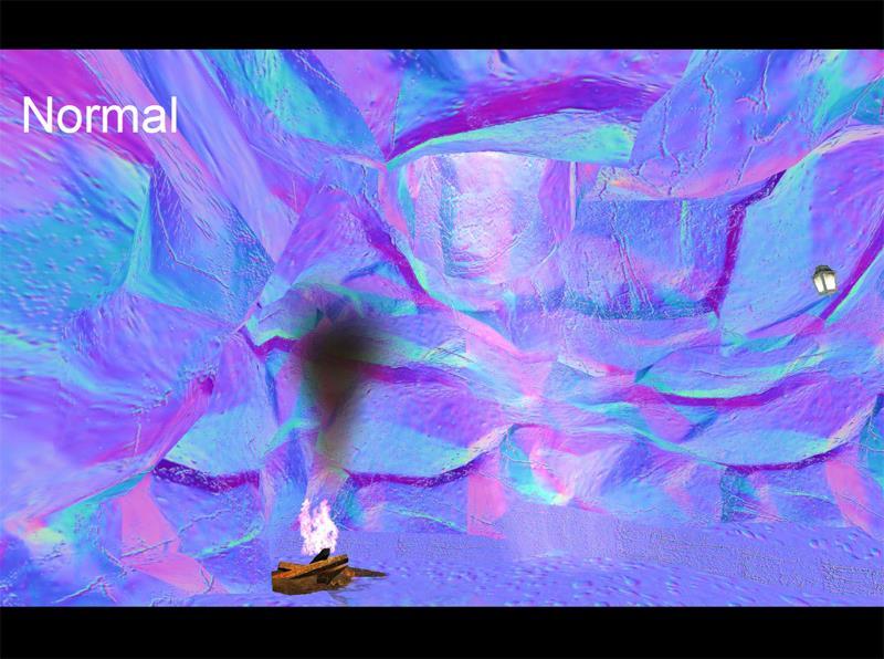
16 Local vs World The Geometry Stage - Model & World Transform A model is composed of vertices and normals Vertices can be thought of as points, which dictate the shape of the object Normals are utilized primarily in lighting to determine the amount of illumination on a surface Vertices and normals are transformed inside the pipeline in the vertex shader 16


17 The Geometry Stage Frustum Eye Coordinates Projection Coordinates Unity Camera Our camera component defines several important items How the screen is cleared and what color The projection type The near and far plane, which can impact the visuals of your scene in several ways 17


18 The Geometry Stage - World & View Transform After world space, we transform into view space The view field is called the View Frustum The purpose of the view camera is to orient the entire world so that the camera is facing down the +/- Z axis (Direct X is Left or positive, OpenGL is Right or negative) The Geometry Stage - World & View Transform There is no spoon - The Matrix The reality behind the camera is that there is no camera While we can create a camera class that operates like a reallife camera, it is still a mathematical abstraction Does not need to follow realworld rules We don t move a camera, we move the world in the opposite direction 18


19 The Geometry Stage - World & View Transform The Geometry Stage - View Transform To transform all of the objects in model space to camera / eye / view space, we invert the camera s transformations. This is accomplished by negating all the terms. 19


20 The Geometry Stage - Projections Our geometry still exists as 3D coordinates Convert the 3D points into homogenous coordinates Orthographic Projection and Perspective Projection Projection involves a volume, with orthographic being a rectangular box and perspective being a frustum All points are normalized between a [1,1,1] and [-1,-1,-1] volume The Geometry Stage - Orthographic Projection Orthographic view: keep lines parallel after being transformed Easiest method: disregard the z value through the following transform P 0 =
21 The Geometry Stage - Orthographic Projection This form of orthographic projection is non-invertible (determinant is zero) Once we step down from 3D to 2D, the data is lost! The Geometry Stage - Orthographic Projection This final cube is called the canonical view volume The coordinates are referred to as the normalized device coordinates 21
22 The Geometry Stage - Orthographic Projection A canonical view volume is created through a translate and scale transform P 0 = S s T t 2 r l t b f n l + r t + b f + n The Geometry Stage - Perspective Projection In a perspective projection, parallel lines converge Meant to represent our own way of viewing the world The father an object is, the smaller it becomes 22

23 The Geometry Stage - Projection Transform The view volume as seen from the side of a camera. The Geometry Stage - Projection Transform A scene waiting to be projected into 2D space 23

24 The Geometry Stage - Projection Transform An example of an orthographic view transformation The Geometry Stage - Projection Transform An example of a perspective view transformation 24


25 GPU Pipeline Overview The GPU implements the geometry and rasterization stages of the pipeline Each of the GPU stages have levels of configurability / programmability Green - full programmability Yellow - configurability Blue - completely fixed 25
26 GPU Pipeline Overview Vertex Shader Implement model and view transform, shading and projection (output is a vertex in eye coordinates) Geometry Shader Optional, operates on points, lines and triangles to destroy or create new primitives Clipping, Screen Mapping, Triangle Setup, Triangle Traversal fixed-function stages (implemented in hardware) Pixel Shader performs the final pixel value from fragments Merger customizable stage for merging buffers Vertex Shader The first stage that performs any graphical processing Deals exclusively with vertices Have access to vertex position, color, normal, UVs and more It is also responsible for transforming vertices from model to homogenous coordinate space 26
27 Vertex Shader Each incoming vertex is processed and outputted The vertex shader can not create or destroy vertices There is no communication between vertices and you don t know the order of processing Vertex Shader Some uses: Object deformations (twists, bends) Procedural deformations for flags and cloth Per-vertex lighting Page curls, heat haze, water ripples The vertex information is passed on to the optional Tessellation/Geometry Stages, Clipping, Screen Mapping Triangle Setup, Triangle Traversal 27

28 Tessellation Control & Evaluation Shaders Process of breaking large primitive patches into smaller primitives before rendering Most common use is to add geometric detail to lower fidelity meshes Has three phases: 1. Tessellation Control Shader 2. Fixed-function tessellation engine 3. Tessellation Evaluation Shader These stages are sandwiched between the vertex shader and geometry shader This shader is OPTIONAL and does not need to be active! Tessellation Control & Evaluation Shaders 28

29 Tessellation Control & Evaluation Shader A patch is a group of vertices Input vertices are referred to as control points Tessellation control shader responsible for: Per-patch inner and outer tessellation factors Position and other attributes for each output control point Per-patch user-defined varyings Tessellation Control defines to the engine how to split up the patch based on inner and outer factors Tessellation Evaluation Shader takes in tessellated points in a coordinate system with respect to the control points Up to YOU to determine final location for points Geometry Shader Located after the vertex shader/tessellation shaders and is optional Input is an object such as triangles, line segments or points and the associated vertices. Unique in that is can generate / transform / delete the amount of data passing through the pipeline Additional vertices outside the processed object can be passed in, which can be utilized for algorithms dependent on nearest-neighbors 29
30 Geometry Shader Optional phase, when not included vertex/tessellation data is interpolated and fed to the fragment shader We specify with layout qualifiers the type of primitive input and the expected primitive output: Input / Ouput Primitive Modes points lines triangles lines_adjacency triangles_adjacency Yes, we can change the input from one mode to another with geometry shaders! Clipping No reason to compute anything outside the view volume Any point that falls completely outside the -1, +1 view cube will not be passed onto the next stage Primitives that are on the boundary require clipping 30


31 Clipping You can also define additional clipping planes to slice the object, referred to as sectioning The clipping stage is almost always controlled by a fixed-operation stage in the 3D hardware. Clipping 31


32 Screen Mapping The X and Y coordinates are transformed into screen coordinates (At this point, we still retain the X, Y & Z coordinates) All three coordinates are referred to as window coordinates All that remains is scaling and translating from -1 to +1 to screen space Screen Mapping We can map the camera s image to only a portion of the scene by manipulating the Viewport Rect We could setup multiple cameras and have them all be visible by manipulating the Viewport Rect Here we see four cameras with four separate views to the window 32
33 Rasterization Stage Conversion of 2D vertices into color pixels (picture elements) This processes is called Rasterization or Scan Conversion. These are fixed-functionality stages! This stage is broken down into the following sub-stages: Rasterization Stage Triangle Setup Data for the triangles are computed for scan conversion and interpolation. Triangle Traversal Each pixel that has its center covered by a triangle has a fragment computed Determines which pixels are covered is called triangle traversal or scan conversion. Fragments are computed using interpolating techniques between the three vertices that make up the triangle 33
34 Pixel Shader Pixel shader can only operate on it s fragments passed in You can not operate on neighboring pixels One exception to this rule and it has to do with gradient calculation You can return: a fragment color depth information, reject processing fragments fog computations alpha testing and more You can have multiple render targets (MRTs) GTA : a-v-graphics-study/ Doom : om-2016-graphics-study/ 34

35 35
36 36
37 37
38 38

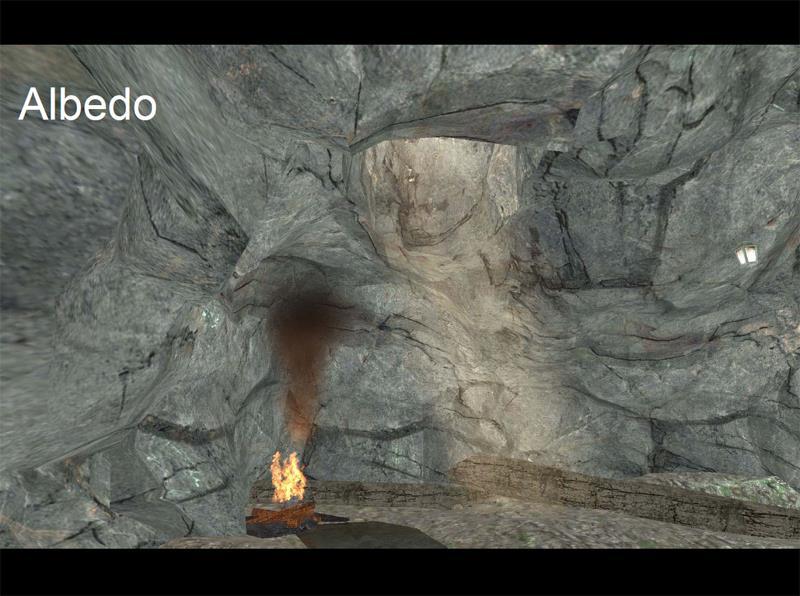
39 Rasterization Pixel Shading Applying textures is performed in this stage UV coordinates are passed from the vertex shader Coordinates are used to lookup the color value for the fragment being processed Merging Stage Depths and colors of the fragments are merged into the frame buffer Stencil Buffer and Z-buffer operations are performed as well as color blending for transparency and compositing This stage features a suite of highly configurable options, but it is not programmable You can specify the mathematical operation utilized during fragment combinations using addition/multiplication/etc and even clamps and bitwise logical operations 39

40 Rasterization - Merging The Z-Buffer contains the current closest fragment on the screen If a new fragment is closer, the z-buffer value is overwritten If it is further away the fragment is discarded. There is a significant weakness with the z-buffer Requires semi-transparent objects to be rendered in proper order from back to front Rasterization - Merging There are additional buffers beyond the color and z- buffer. Alpha channel Alpha checks can be processed and fragments discarded if they do not match a set alpha value. Stencil buffer An offscreen buffer to record the locations of rendered primitives. Can create cut outs and only allow certain parts of our screen rendered. (Good for reflections) Frame buffer This is actually every buffer utilized in the application, however sometimes it is referred to as the combined Z and color buffers Accumulation Buffer Accumulation of multiple frames into one buffer. (Can be used for motion blur or depth of fields and a number of other effects) 40
41 Rasterization - Merging This is the end of the pipeline All primitives are now rasterized A double buffer is utilized where graphics are drawn to an internal (not visible) buffer Either a bit swap is performed or a pointer swap and the monitor is update with the new image In this lab a technique called quad buffering is employed Utilizes 4 buffers, two for each eye, one front and one back buffer Requires additional memory and processing time 41
Rasterization Overview
 Rendering Overview The process of generating an image given a virtual camera objects light sources Various techniques rasterization (topic of this course) raytracing (topic of the course Advanced Computer
CS451Real-time Rendering Pipeline
 1 CS451Real-time Rendering Pipeline JYH-MING LIEN DEPARTMENT OF COMPUTER SCIENCE GEORGE MASON UNIVERSITY Based on Tomas Akenine-Möller s lecture note You say that you render a 3D 2 scene, but what does
The Application Stage. The Game Loop, Resource Management and Renderer Design
 1 The Application Stage The Game Loop, Resource Management and Renderer Design Application Stage Responsibilities 2 Set up the rendering pipeline Resource Management 3D meshes Textures etc. Prepare data
Rendering. Converting a 3D scene to a 2D image. Camera. Light. Rendering. View Plane
 Rendering Pipeline Rendering Converting a 3D scene to a 2D image Rendering Light Camera 3D Model View Plane Rendering Converting a 3D scene to a 2D image Basic rendering tasks: Modeling: creating the world
Rendering Objects. Need to transform all geometry then
 Intro to OpenGL Rendering Objects Object has internal geometry (Model) Object relative to other objects (World) Object relative to camera (View) Object relative to screen (Projection) Need to transform
Scanline Rendering 2 1/42
 Scanline Rendering 2 1/42 Review 1. Set up a Camera the viewing frustum has near and far clipping planes 2. Create some Geometry made out of triangles 3. Place the geometry in the scene using Transforms
The Rasterization Pipeline
 Lecture 5: The Rasterization Pipeline (and its implementation on GPUs) Computer Graphics CMU 15-462/15-662, Fall 2015 What you know how to do (at this point in the course) y y z x (w, h) z x Position objects
Pipeline Operations. CS 4620 Lecture Steve Marschner. Cornell CS4620 Spring 2018 Lecture 11
 Pipeline Operations CS 4620 Lecture 11 1 Pipeline you are here APPLICATION COMMAND STREAM 3D transformations; shading VERTEX PROCESSING TRANSFORMED GEOMETRY conversion of primitives to pixels RASTERIZATION
Spring 2009 Prof. Hyesoon Kim
 Spring 2009 Prof. Hyesoon Kim Application Geometry Rasterizer CPU Each stage cane be also pipelined The slowest of the pipeline stage determines the rendering speed. Frames per second (fps) Executes on
Spring 2011 Prof. Hyesoon Kim
 Spring 2011 Prof. Hyesoon Kim Application Geometry Rasterizer CPU Each stage cane be also pipelined The slowest of the pipeline stage determines the rendering speed. Frames per second (fps) Executes on
Pipeline Operations. CS 4620 Lecture 14
 Pipeline Operations CS 4620 Lecture 14 2014 Steve Marschner 1 Pipeline you are here APPLICATION COMMAND STREAM 3D transformations; shading VERTEX PROCESSING TRANSFORMED GEOMETRY conversion of primitives
CS 354R: Computer Game Technology
 CS 354R: Computer Game Technology Texture and Environment Maps Fall 2018 Texture Mapping Problem: colors, normals, etc. are only specified at vertices How do we add detail between vertices without incurring
Graphics and Interaction Rendering pipeline & object modelling
 433-324 Graphics and Interaction Rendering pipeline & object modelling Department of Computer Science and Software Engineering The Lecture outline Introduction to Modelling Polygonal geometry The rendering
Tutorial on GPU Programming #2. Joong-Youn Lee Supercomputing Center, KISTI
 Tutorial on GPU Programming #2 Joong-Youn Lee Supercomputing Center, KISTI Contents Graphics Pipeline Vertex Programming Fragment Programming Introduction to Cg Language Graphics Pipeline The process to
Adaptive Point Cloud Rendering
 1 Adaptive Point Cloud Rendering Project Plan Final Group: May13-11 Christopher Jeffers Eric Jensen Joel Rausch Client: Siemens PLM Software Client Contact: Michael Carter Adviser: Simanta Mitra 4/29/13
Computer Graphics. Lecture 02 Graphics Pipeline. Edirlei Soares de Lima.
 Computer Graphics Lecture 02 Graphics Pipeline Edirlei Soares de Lima What is the graphics pipeline? The Graphics Pipeline is a special software/hardware subsystem
Surface Graphics. 200 polys 1,000 polys 15,000 polys. an empty foot. - a mesh of spline patches:
 Surface Graphics Objects are explicitely defined by a surface or boundary representation (explicit inside vs outside) This boundary representation can be given by: - a mesh of polygons: 200 polys 1,000
C P S C 314 S H A D E R S, O P E N G L, & J S RENDERING PIPELINE. Mikhail Bessmeltsev
 C P S C 314 S H A D E R S, O P E N G L, & J S RENDERING PIPELINE UGRAD.CS.UBC.C A/~CS314 Mikhail Bessmeltsev 1 WHAT IS RENDERING? Generating image from a 3D scene 2 WHAT IS RENDERING? Generating image
CSE 167: Introduction to Computer Graphics Lecture #4: Vertex Transformation
 CSE 167: Introduction to Computer Graphics Lecture #4: Vertex Transformation Jürgen P. Schulze, Ph.D. University of California, San Diego Fall Quarter 2013 Announcements Project 2 due Friday, October 11
Game Architecture. 2/19/16: Rasterization
 Game Architecture 2/19/16: Rasterization Viewing To render a scene, need to know Where am I and What am I looking at The view transform is the matrix that does this Maps a standard view space into world
CS 381 Computer Graphics, Fall 2008 Midterm Exam Solutions. The Midterm Exam was given in class on Thursday, October 23, 2008.
 CS 381 Computer Graphics, Fall 2008 Midterm Exam Solutions The Midterm Exam was given in class on Thursday, October 23, 2008. 1. [4 pts] Drawing Where? Your instructor says that objects should always be
graphics pipeline computer graphics graphics pipeline 2009 fabio pellacini 1
 graphics pipeline computer graphics graphics pipeline 2009 fabio pellacini 1 graphics pipeline sequence of operations to generate an image using object-order processing primitives processed one-at-a-time
CS4620/5620: Lecture 14 Pipeline
 CS4620/5620: Lecture 14 Pipeline 1 Rasterizing triangles Summary 1! evaluation of linear functions on pixel grid 2! functions defined by parameter values at vertices 3! using extra parameters to determine
Chapter 5. Projections and Rendering
 Chapter 5 Projections and Rendering Topics: Perspective Projections The rendering pipeline In order to view manipulate and view a graphics object we must find ways of storing it a computer-compatible way.
CHAPTER 1 Graphics Systems and Models 3
 ?????? 1 CHAPTER 1 Graphics Systems and Models 3 1.1 Applications of Computer Graphics 4 1.1.1 Display of Information............. 4 1.1.2 Design.................... 5 1.1.3 Simulation and Animation...........
graphics pipeline computer graphics graphics pipeline 2009 fabio pellacini 1
 graphics pipeline computer graphics graphics pipeline 2009 fabio pellacini 1 graphics pipeline sequence of operations to generate an image using object-order processing primitives processed one-at-a-time
COMP30019 Graphics and Interaction Rendering pipeline & object modelling
 COMP30019 Graphics and Interaction Rendering pipeline & object modelling Department of Computer Science and Software Engineering The Lecture outline Introduction to Modelling Polygonal geometry The rendering
Lecture outline. COMP30019 Graphics and Interaction Rendering pipeline & object modelling. Introduction to modelling
 Lecture outline COMP30019 Graphics and Interaction Rendering pipeline & object modelling Department of Computer Science and Software Engineering The Introduction to Modelling Polygonal geometry The rendering
Lecture 2. Shaders, GLSL and GPGPU
 Lecture 2 Shaders, GLSL and GPGPU Is it interesting to do GPU computing with graphics APIs today? Lecture overview Why care about shaders for computing? Shaders for graphics GLSL Computing with shaders
Enhancing Traditional Rasterization Graphics with Ray Tracing. October 2015
 Enhancing Traditional Rasterization Graphics with Ray Tracing October 2015 James Rumble Developer Technology Engineer, PowerVR Graphics Overview Ray Tracing Fundamentals PowerVR Ray Tracing Pipeline Using
3D GRAPHICS. design. animate. render
 3D GRAPHICS design animate render 3D animation movies Computer Graphics Special effects Computer Graphics Advertising Computer Graphics Games Computer Graphics Simulations & serious games Computer Graphics
Real-Time Rendering (Echtzeitgraphik) Michael Wimmer
 Michael Wimmer") Real-Time Rendering (Echtzeitgraphik) Michael Wimmer wimmer@cg.tuwien.ac.at Walking down the graphics pipeline Application Geometry Rasterizer What for? Understanding the rendering pipeline is the key
Real-Time Rendering (Echtzeitgraphik) Michael Wimmer wimmer@cg.tuwien.ac.at Walking down the graphics pipeline Application Geometry Rasterizer What for? Understanding the rendering pipeline is the key
CSE 167: Lecture #5: Rasterization. Jürgen P. Schulze, Ph.D. University of California, San Diego Fall Quarter 2012
 CSE 167: Introduction to Computer Graphics Lecture #5: Rasterization Jürgen P. Schulze, Ph.D. University of California, San Diego Fall Quarter 2012 Announcements Homework project #2 due this Friday, October
Today. Rendering pipeline. Rendering pipeline. Object vs. Image order. Rendering engine Rendering engine (jtrt) Computergrafik. Rendering pipeline
 Computergrafik. Rendering pipeline") Computergrafik Today Rendering pipeline s View volumes, clipping Viewport Matthias Zwicker Universität Bern Herbst 2008 Rendering pipeline Rendering pipeline Hardware & software that draws 3D scenes on
Computergrafik Today Rendering pipeline s View volumes, clipping Viewport Matthias Zwicker Universität Bern Herbst 2008 Rendering pipeline Rendering pipeline Hardware & software that draws 3D scenes on
Models and The Viewing Pipeline. Jian Huang CS456
 Models and The Viewing Pipeline Jian Huang CS456 Vertex coordinates list, polygon table and (maybe) edge table Auxiliary: Per vertex normal Neighborhood information, arranged with regard to vertices and
Texturing Theory. Overview. All it takes is for the rendered image to look right. -Jim Blinn 11/10/2018
 References: Real-Time Rendering 3 rd Edition Chapter 6 Texturing Theory All it takes is for the rendered image to look right. -Jim Blinn Overview Introduction The Texturing Pipeline Example The Projector
TSBK03 Screen-Space Ambient Occlusion
 TSBK03 Screen-Space Ambient Occlusion Joakim Gebart, Jimmy Liikala December 15, 2013 Contents 1 Abstract 1 2 History 2 2.1 Crysis method..................................... 2 3 Chosen method 2 3.1 Algorithm
CSE 167: Introduction to Computer Graphics Lecture #9: Visibility. Jürgen P. Schulze, Ph.D. University of California, San Diego Fall Quarter 2018
 CSE 167: Introduction to Computer Graphics Lecture #9: Visibility Jürgen P. Schulze, Ph.D. University of California, San Diego Fall Quarter 2018 Announcements Midterm Scores are on TritonEd Exams to be
CSE 167: Introduction to Computer Graphics Lecture #10: View Frustum Culling
 CSE 167: Introduction to Computer Graphics Lecture #10: View Frustum Culling Jürgen P. Schulze, Ph.D. University of California, San Diego Fall Quarter 2015 Announcements Project 4 due tomorrow Project
Graphics Programming. Computer Graphics, VT 2016 Lecture 2, Chapter 2. Fredrik Nysjö Centre for Image analysis Uppsala University
 Graphics Programming Computer Graphics, VT 2016 Lecture 2, Chapter 2 Fredrik Nysjö Centre for Image analysis Uppsala University Graphics programming Typically deals with How to define a 3D scene with a
Notes on Assignment. Notes on Assignment. Notes on Assignment. Notes on Assignment
 Notes on Assignment Notes on Assignment Objects on screen - made of primitives Primitives are points, lines, polygons - watch vertex ordering The main object you need is a box When the MODELVIEW matrix
2D rendering takes a photo of the 2D scene with a virtual camera that selects an axis aligned rectangle from the scene. The photograph is placed into
 2D rendering takes a photo of the 2D scene with a virtual camera that selects an axis aligned rectangle from the scene. The photograph is placed into the viewport of the current application window. A pixel
Graphics Hardware. Instructor Stephen J. Guy
 Instructor Stephen J. Guy Overview What is a GPU Evolution of GPU GPU Design Modern Features Programmability! Programming Examples Overview What is a GPU Evolution of GPU GPU Design Modern Features Programmability!
CSE 690: GPGPU. Lecture 2: Understanding the Fabric - Intro to Graphics. Klaus Mueller Stony Brook University Computer Science Department
 CSE 690: GPGPU Lecture 2: Understanding the Fabric - Intro to Graphics Klaus Mueller Stony Brook University Computer Science Department Klaus Mueller, Stony Brook 2005 1 Surface Graphics Objects are explicitely
CSE 167: Introduction to Computer Graphics Lecture #11: Visibility Culling
 CSE 167: Introduction to Computer Graphics Lecture #11: Visibility Culling Jürgen P. Schulze, Ph.D. University of California, San Diego Fall Quarter 2017 Announcements Project 3 due Monday Nov 13 th at
Buffers, Textures, Compositing, and Blending. Overview. Buffers. David Carr Virtual Environments, Fundamentals Spring 2005 Based on Slides by E.
 INSTITUTIONEN FÖR SYSTEMTEKNIK LULEÅ TEKNISKA UNIVERSITET Buffers, Textures, Compositing, and Blending David Carr Virtual Environments, Fundamentals Spring 2005 Based on Slides by E. Angel Compositing,
CSC Graphics Programming. Budditha Hettige Department of Statistics and Computer Science
 CSC 307 1.0 Graphics Programming Department of Statistics and Computer Science Graphics Programming 2 Common Uses for Computer Graphics Applications for real-time 3D graphics range from interactive games
Ulf Assarsson Department of Computer Engineering Chalmers University of Technology
 Ulf Assarsson Department of Computer Engineering Chalmers University of Technology Tracing Photons One way to form an image is to follow rays of light from a point source finding which rays enter the lens
Optimizing and Profiling Unity Games for Mobile Platforms. Angelo Theodorou Senior Software Engineer, MPG Gamelab 2014, 25 th -27 th June
 Optimizing and Profiling Unity Games for Mobile Platforms Angelo Theodorou Senior Software Engineer, MPG Gamelab 2014, 25 th -27 th June 1 Agenda Introduction ARM and the presenter Preliminary knowledge
Computer Graphics (CS 543) Lecture 10: Soft Shadows (Maps and Volumes), Normal and Bump Mapping
 Lecture 10: Soft Shadows (Maps and Volumes), Normal and Bump Mapping") Computer Graphics (CS 543) Lecture 10: Soft Shadows (Maps and Volumes), Normal and Bump Mapping Prof Emmanuel Agu Computer Science Dept. Worcester Polytechnic Institute (WPI) Shadow Buffer Theory Observation:
Computer Graphics (CS 543) Lecture 10: Soft Shadows (Maps and Volumes), Normal and Bump Mapping Prof Emmanuel Agu Computer Science Dept. Worcester Polytechnic Institute (WPI) Shadow Buffer Theory Observation:
CSE 167: Introduction to Computer Graphics Lecture #5: Rasterization. Jürgen P. Schulze, Ph.D. University of California, San Diego Fall Quarter 2015
 CSE 167: Introduction to Computer Graphics Lecture #5: Rasterization Jürgen P. Schulze, Ph.D. University of California, San Diego Fall Quarter 2015 Announcements Project 2 due tomorrow at 2pm Grading window
The Graphics Pipeline
 The Graphics Pipeline Ray Tracing: Why Slow? Basic ray tracing: 1 ray/pixel Ray Tracing: Why Slow? Basic ray tracing: 1 ray/pixel But you really want shadows, reflections, global illumination, antialiasing
CSE 167: Lecture #4: Vertex Transformation. Jürgen P. Schulze, Ph.D. University of California, San Diego Fall Quarter 2012
 CSE 167: Introduction to Computer Graphics Lecture #4: Vertex Transformation Jürgen P. Schulze, Ph.D. University of California, San Diego Fall Quarter 2012 Announcements Project 2 due Friday, October 12
Bringing AAA graphics to mobile platforms. Niklas Smedberg Senior Engine Programmer, Epic Games
 Bringing AAA graphics to mobile platforms Niklas Smedberg Senior Engine Programmer, Epic Games Who Am I A.k.a. Smedis Platform team at Epic Games Unreal Engine 15 years in the industry 30 years of programming
Enhancing Traditional Rasterization Graphics with Ray Tracing. March 2015
 Enhancing Traditional Rasterization Graphics with Ray Tracing March 2015 Introductions James Rumble Developer Technology Engineer Ray Tracing Support Justin DeCell Software Design Engineer Ray Tracing
Shadow Algorithms. CSE 781 Winter Han-Wei Shen
 Shadow Algorithms CSE 781 Winter 2010 Han-Wei Shen Why Shadows? Makes 3D Graphics more believable Provides additional cues for the shapes and relative positions of objects in 3D What is shadow? Shadow:
Deferred Rendering Due: Wednesday November 15 at 10pm
 CMSC 23700 Autumn 2017 Introduction to Computer Graphics Project 4 November 2, 2017 Deferred Rendering Due: Wednesday November 15 at 10pm 1 Summary This assignment uses the same application architecture
Pipeline Operations. CS 4620 Lecture 10
 Pipeline Operations CS 4620 Lecture 10 2008 Steve Marschner 1 Hidden surface elimination Goal is to figure out which color to make the pixels based on what s in front of what. Hidden surface elimination
GUERRILLA DEVELOP CONFERENCE JULY 07 BRIGHTON
 Deferred Rendering in Killzone 2 Michal Valient Senior Programmer, Guerrilla Talk Outline Forward & Deferred Rendering Overview G-Buffer Layout Shader Creation Deferred Rendering in Detail Rendering Passes
CS230 : Computer Graphics Lecture 4. Tamar Shinar Computer Science & Engineering UC Riverside
 CS230 : Computer Graphics Lecture 4 Tamar Shinar Computer Science & Engineering UC Riverside Shadows Shadows for each pixel do compute viewing ray if ( ray hits an object with t in [0, inf] ) then compute
Computer graphics 2: Graduate seminar in computational aesthetics
 Computer graphics 2: Graduate seminar in computational aesthetics Angus Forbes evl.uic.edu/creativecoding/cs526 Homework 2 RJ ongoing... - Follow the suggestions in the Research Journal handout and find
The Graphics Pipeline and OpenGL I: Transformations!
 ! The Graphics Pipeline and OpenGL I: Transformations! Gordon Wetzstein! Stanford University! EE 267 Virtual Reality! Lecture 2! stanford.edu/class/ee267/!! Albrecht Dürer, Underweysung der Messung mit
PowerVR Hardware. Architecture Overview for Developers
 Public Imagination Technologies PowerVR Hardware Public. This publication contains proprietary information which is subject to change without notice and is supplied 'as is' without warranty of any kind.
Hardware-driven visibility culling
 Hardware-driven visibility culling I. Introduction 20073114 김정현 The goal of the 3D graphics is to generate a realistic and accurate 3D image. To achieve this, it needs to process not only large amount
OpenGL: Open Graphics Library. Introduction to OpenGL Part II. How do I render a geometric primitive? What is OpenGL
 OpenGL: Open Graphics Library Introduction to OpenGL Part II CS 351-50 Graphics API ( Application Programming Interface) Software library Layer between programmer and graphics hardware (and other software
2.11 Particle Systems
 2.11 Particle Systems 320491: Advanced Graphics - Chapter 2 152 Particle Systems Lagrangian method not mesh-based set of particles to model time-dependent phenomena such as snow fire smoke 320491: Advanced
Performance OpenGL Programming (for whatever reason)
") Performance OpenGL Programming (for whatever reason) Mike Bailey Oregon State University Performance Bottlenecks In general there are four places a graphics system can become bottlenecked: 1. The computer
Performance OpenGL Programming (for whatever reason) Mike Bailey Oregon State University Performance Bottlenecks In general there are four places a graphics system can become bottlenecked: 1. The computer
CS130 : Computer Graphics Lecture 2: Graphics Pipeline. Tamar Shinar Computer Science & Engineering UC Riverside
 CS130 : Computer Graphics Lecture 2: Graphics Pipeline Tamar Shinar Computer Science & Engineering UC Riverside Raster Devices and Images Raster Devices - raster displays show images as a rectangular array
CMSC427 Advanced shading getting global illumination by local methods. Credit: slides Prof. Zwicker
 CMSC427 Advanced shading getting global illumination by local methods Credit: slides Prof. Zwicker Topics Shadows Environment maps Reflection mapping Irradiance environment maps Ambient occlusion Reflection
2: Introducing image synthesis. Some orientation how did we get here? Graphics system architecture Overview of OpenGL / GLU / GLUT
 COMP27112 Computer Graphics and Image Processing 2: Introducing image synthesis Toby.Howard@manchester.ac.uk 1 Introduction In these notes we ll cover: Some orientation how did we get here? Graphics system
Enabling immersive gaming experiences Intro to Ray Tracing
 Enabling immersive gaming experiences Intro to Ray Tracing Overview What is Ray Tracing? Why Ray Tracing? PowerVR Wizard Architecture Example Content Unity Hybrid Rendering Demonstration 3 What is Ray
Could you make the XNA functions yourself?
 1 Could you make the XNA functions yourself? For the second and especially the third assignment, you need to globally understand what s going on inside the graphics hardware. You will write shaders, which
CS 4620 Program 3: Pipeline
 CS 4620 Program 3: Pipeline out: Wednesday 14 October 2009 due: Friday 30 October 2009 1 Introduction In this assignment, you will implement several types of shading in a simple software graphics pipeline.
The Rendering Pipeline (1)
") The Rendering Pipeline (1) Alessandro Martinelli alessandro.martinelli@unipv.it 30 settembre 2014 The Rendering Pipeline (1) Rendering Architecture First Rendering Pipeline Second Pipeline: Illumination
The Rendering Pipeline (1) Alessandro Martinelli alessandro.martinelli@unipv.it 30 settembre 2014 The Rendering Pipeline (1) Rendering Architecture First Rendering Pipeline Second Pipeline: Illumination
Cloth Simulation on the GPU. Cyril Zeller NVIDIA Corporation
 Cloth Simulation on the GPU Cyril Zeller NVIDIA Corporation Overview A method to simulate cloth on any GPU supporting Shader Model 3 (Quadro FX 4500, 4400, 3400, 1400, 540, GeForce 6 and above) Takes advantage
Rendering Grass with Instancing in DirectX* 10
 Rendering Grass with Instancing in DirectX* 10 By Anu Kalra Because of the geometric complexity, rendering realistic grass in real-time is difficult, especially on consumer graphics hardware. This article
Lecture 3 Sections 2.2, 4.4. Mon, Aug 31, 2009
 Model s Lecture 3 Sections 2.2, 4.4 World s Eye s Clip s s s Window s Hampden-Sydney College Mon, Aug 31, 2009 Outline Model s World s Eye s Clip s s s Window s 1 2 3 Model s World s Eye s Clip s s s Window
CS GPU and GPGPU Programming Lecture 2: Introduction; GPU Architecture 1. Markus Hadwiger, KAUST
 CS 380 - GPU and GPGPU Programming Lecture 2: Introduction; GPU Architecture 1 Markus Hadwiger, KAUST Reading Assignment #2 (until Feb. 17) Read (required): GLSL book, chapter 4 (The OpenGL Programmable
Shadows in the graphics pipeline
 Shadows in the graphics pipeline Steve Marschner Cornell University CS 569 Spring 2008, 19 February There are a number of visual cues that help let the viewer know about the 3D relationships between objects
Real-Time Graphics Architecture
 Real-Time Graphics Architecture Kurt Akeley Pat Hanrahan http://www.graphics.stanford.edu/courses/cs448a-01-fall Geometry Outline Vertex and primitive operations System examples emphasis on clipping Primitive
3D Programming. 3D Programming Concepts. Outline. 3D Concepts. 3D Concepts -- Coordinate Systems. 3D Concepts Displaying 3D Models
 3D Programming Concepts Outline 3D Concepts Displaying 3D Models 3D Programming CS 4390 3D Computer 1 2 3D Concepts 3D Model is a 3D simulation of an object. Coordinate Systems 3D Models 3D Shapes 3D Concepts
WebGL (Web Graphics Library) is the new standard for 3D graphics on the Web, designed for rendering 2D graphics and interactive 3D graphics.
 is the new standard for 3D graphics on the Web, designed for rendering 2D graphics and interactive 3D graphics.") About the Tutorial WebGL (Web Graphics Library) is the new standard for 3D graphics on the Web, designed for rendering 2D graphics and interactive 3D graphics. This tutorial starts with a basic introduction
About the Tutorial WebGL (Web Graphics Library) is the new standard for 3D graphics on the Web, designed for rendering 2D graphics and interactive 3D graphics. This tutorial starts with a basic introduction
EECE 478. Learning Objectives. Learning Objectives. Rasterization & Scenes. Rasterization. Compositing
 EECE 478 Rasterization & Scenes Rasterization Learning Objectives Be able to describe the complete graphics pipeline. Describe the process of rasterization for triangles and lines. Compositing Manipulate
CSE328 Fundamentals of Computer Graphics
 CSE328 Fundamentals of Computer Graphics Hong Qin State University of New York at Stony Brook (Stony Brook University) Stony Brook, New York 794--44 Tel: (63)632-845; Fax: (63)632-8334 qin@cs.sunysb.edu
Ciril Bohak. - INTRODUCTION TO WEBGL
 2016 Ciril Bohak ciril.bohak@fri.uni-lj.si - INTRODUCTION TO WEBGL What is WebGL? WebGL (Web Graphics Library) is an implementation of OpenGL interface for cmmunication with graphical hardware, intended
Real - Time Rendering. Graphics pipeline. Michal Červeňanský Juraj Starinský
 Real - Time Rendering Graphics pipeline Michal Červeňanský Juraj Starinský Overview History of Graphics HW Rendering pipeline Shaders Debugging 2 History of Graphics HW First generation Second generation
OpenGl Pipeline. triangles, lines, points, images. Per-vertex ops. Primitive assembly. Texturing. Rasterization. Per-fragment ops.
 OpenGl Pipeline Individual Vertices Transformed Vertices Commands Processor Per-vertex ops Primitive assembly triangles, lines, points, images Primitives Fragments Rasterization Texturing Per-fragment
Hands-On Workshop: 3D Automotive Graphics on Connected Radios Using Rayleigh and OpenGL ES 2.0
 Hands-On Workshop: 3D Automotive Graphics on Connected Radios Using Rayleigh and OpenGL ES 2.0 FTF-AUT-F0348 Hugo Osornio Luis Olea A P R. 2 0 1 4 TM External Use Agenda Back to the Basics! What is a GPU?
Module Contact: Dr Stephen Laycock, CMP Copyright of the University of East Anglia Version 1
 UNIVERSITY OF EAST ANGLIA School of Computing Sciences Main Series PG Examination 2013-14 COMPUTER GAMES DEVELOPMENT CMPSME27 Time allowed: 2 hours Answer any THREE questions. (40 marks each) Notes are
Introduction to Visualization and Computer Graphics
 Introduction to Visualization and Computer Graphics DH2320, Fall 2015 Prof. Dr. Tino Weinkauf Introduction to Visualization and Computer Graphics Visibility Shading 3D Rendering Geometric Model Color Perspective
CS 130 Exam I. Fall 2015
 S 3 Exam I Fall 25 Name Student ID Signature You may not ask any questions during the test. If you believe that there is something wrong with a question, write down what you think the question is trying
Lecture 4. Viewing, Projection and Viewport Transformations
 Notes on Assignment Notes on Assignment Hw2 is dependent on hw1 so hw1 and hw2 will be graded together i.e. You have time to finish both by next monday 11:59p Email list issues - please cc: elif@cs.nyu.edu
Course Title: Computer Graphics Course no: CSC209
 Course Title: Computer Graphics Course no: CSC209 Nature of the Course: Theory + Lab Semester: III Full Marks: 60+20+20 Pass Marks: 24 +8+8 Credit Hrs: 3 Course Description: The course coversconcepts of
CSE528 Computer Graphics: Theory, Algorithms, and Applications
 CSE528 Computer Graphics: Theory, Algorithms, and Applications Hong Qin Stony Brook University (SUNY at Stony Brook) Stony Brook, New York 11794-2424 Tel: (631)632-845; Fax: (631)632-8334 qin@cs.stonybrook.edu
Chapter IV Fragment Processing and Output Merging. 3D Graphics for Game Programming
 Chapter IV Fragment Processing and Output Merging Fragment Processing The per-fragment attributes may include a normal vector, a set of texture coordinates, a set of color values, a depth, etc. Using these
Culling. Computer Graphics CSE 167 Lecture 12
 Culling Computer Graphics CSE 167 Lecture 12 CSE 167: Computer graphics Culling Definition: selecting from a large quantity In computer graphics: selecting primitives (or batches of primitives) that are
Drawing Fast The Graphics Pipeline
 Drawing Fast The Graphics Pipeline CS559 Fall 2015 Lecture 9 October 1, 2015 What I was going to say last time How are the ideas we ve learned about implemented in hardware so they are fast. Important:
https://ilearn.marist.edu/xsl-portal/tool/d4e4fd3a-a3...
 Assessment Preview - This is an example student view of this assessment done Exam 2 Part 1 of 5 - Modern Graphics Pipeline Question 1 of 27 Match each stage in the graphics pipeline with a description
Models and Architectures
 Models and Architectures Objectives Learn the basic design of a graphics system Introduce graphics pipeline architecture Examine software components for an interactive graphics system 1 Image Formation
Today s Agenda. Basic design of a graphics system. Introduction to OpenGL
 Today s Agenda Basic design of a graphics system Introduction to OpenGL Image Compositing Compositing one image over another is most common choice can think of each image drawn on a transparent plastic