2D rendering takes a photo of the 2D scene with a virtual camera that selects an axis aligned rectangle from the scene. The photograph is placed into
|
|
|
- Magdalene O’Neal’
- 5 years ago
- Views:
Transcription
1

2 2D rendering takes a photo of the 2D scene with a virtual camera that selects an axis aligned rectangle from the scene. The photograph is placed into the viewport of the current application window. A pixel driven solution of this problem would visit the pixels of the viewport one by one, transform the pixel center back to the 2D virtual world, and determine which object contains this point. If several objects contained this point, the one with the highest priority is retained. The pixel is colored with the color of the selected object.

3 The core of a pixel driven algorithm is containment test, i.e. the determination whether a point is in the set of a 2D object. If the object is defined implicitly, this is usually equivalent to the check of the sign of the implicit equation. If the boundary of the object is defined, e.g. with parametric curve, whether or not a point is inside should be determined by counting how many times the boundary is crossed until infinity is reached from this point. If this is an odd number the point is inside, otherwise, outside.
4 2D rendering is a sequence, called pipeline, of computation steps. We start with the objects defined in their reference state, which can include points, parametric or implicit curves, 2D regions with curve boundaries. As we shall transform these objects, we they are vectorized, so curves are approximated by polylines and regions by polygons. The rendering pipeline thus processes only point, line (polyline) and triangle (polygon) primitives. Modeling transformation places the object in world coordinates. This typically involves scaling, rotation and translation to set the size, orientation and the position of the object. In world, objects meet each other and also the 2D camera, which is the window AABB (axis aligned bounding box or rectangle). We wish to see the content of the window in the picture on the screen, called viewport. Thus, screen projection transforms the world in a way that the window rectangle is mapped onto the viewport rectangle. This can be done in a single step, or in two steps when first the window is transformed to a square of corners (-1,-1) and (1,1) and then from here to the physical screen. Clipping removes those objects parts that are outside of the camera window, or alternatively outside of the viewport in screen, or outside of the square of corners (-1,-1) and (1,1) in normalized device space. The advantage of normalized device space becomes obvious now. Clipping here is independent of the resolution and of the window, so can be easily implemented in a fix hardware. Having transformed primitives onto the screen, where the unit is the pixel, they are rasterized. Algorithms find those sets of pixels which can provide the illusion of a line segment or a polygon.

5 Vectorization is executed by our program running on the CPU since the GPU expects lines and triangles. The other steps are mapped onto the GPU stages.
6 Vectorization is trivial for parametric curves. The parametric range is decomposed and increasing sample values are substituted into the equation of the curve, resulting in a sequence of points on the curve. Introducing a line segment between each subsequent pair of points, the curve is approximated by line segments. If the curve is closed, using the same strategy, a polygon approximation of the region can be found.
, and processing algorithms will be uniform and independent of")
7 Polylines are often further decomposed to line segments and polygons to triangles. Such a decomposition has the advantage that the resulting data element has constant size (a line segment has 2 vertices a triangle has 3), and processing algorithms will be uniform and independent of the size of the data element. Polylines can be easily decomposed to line segments. However, polygons are not so simple to decompose to triangles unless the polygon is convex. A polygon is broken down to smaller polygons and eventually to triangles by cutting them along diagonals. A diagonal is a line segment connecting two non-neighboring vertices, that is fully contained by the polygon. If the polygon is convex, then any line segment connecting two non-neighboring vertices is fully contained by the polygon (this is the definition of convexity), thus all of them are diagonals. This is not the case for concave polygons, when line segments connecting vertices can intersect edges or can fully be outside of the polygon. The good news is that all polygons, even concave ones, have diagonals, so they can be broken to triangles by diagonals (prove it). An even better news is that any polygon of at least 4 vertices has special diagonals, that allow exactly one triangle to be cut.

8 A vertex is an ear if the line segment between its previous and next vertices is a diagonal. According to the two ears theorem, every polygon of at least 4 vertices has at least two ears. So triangle decomposition should just search for ears and cut them until a single triangle remains. The proof of the two ears theorem is based on the recognition that any polygon can be broken down to triangles by diagonals. Let us start with one possible decomposition, and consider triangles as nodes of a graph, and add edges to this graph where two triangles share a diagonal. This graph is a tree since it is connected (the polygon is a single piece) and cutting every edge, the graph falls apart, i.e. there is no circle in it. By induction, it is easy to prove that every tree of at least 2 nodes has at least two leaves, which correspond to two ears.
9 For every step, we check whether or not a vertex is an ear. The line segment of its previous and next vertices is tested whether it is a diagonal. This is done by checking whether the line segment intersects any other edge (if it does, it is not a diagonal). If there is no intersection, we should determine whether the line segment is fully outside. Selecting an arbitrary inner point, e.g. the middle, we check whether this point is inside the polygon. By definition, a point is inside if traveling from this point to infinity, the polygon boundary is intersected odd number of times.
10 The first relevant step of rendering is placing the reference state primitives in world, typically scaling, rotating and finally translating its vertices. Recall that it is enough to execute these transformations to vertices, because points, lines and polygons are preserved by homogeneous linear transformations. These are affine transformations, and the resulting modeling transformation matrix will also be an affine transformation. If the third column is 0,0,1, then other matrix elements have an intuitive meaning, they specify what happens with basis vector i, basis vector j, and the origin itself.

11 To do transformations on the CPU, we use the following mat4 class. This type is built in GLSL as well.
12 Screen projection maps the window rectangle, which is the camera in 2D, onto the viewport rectangle, which can be imagined as the photograph. This simple projection is usually executed in two steps, first transforming the window onto a normalized square, and then transforming the square to the viewport. Transforming the window to a origin centered square of corners (-1,-1) and (1,1) is a sequence of two transformations: a translation that moves the center of the camera window to the origin; a scaling that modifies the window width and height to 2. These are affine transformations that can also be given as a matrix.
13 Projection is a scaling that makes the size of the window a square of edge length 2 while keeping the center in the origin. It might seem an over complication, but in 3D we use the same steps of view and projection transformations and they will be more complicated. The other advantage of separating view and projection transformations is that it is easy to invert the transformation in this form.

14 A 2D camera is thus represented by the center and the size of the camera window and is associated with view and projection transformations, as well as their inverse. Zoom and pan are just the modifications of the size and center, respectively.
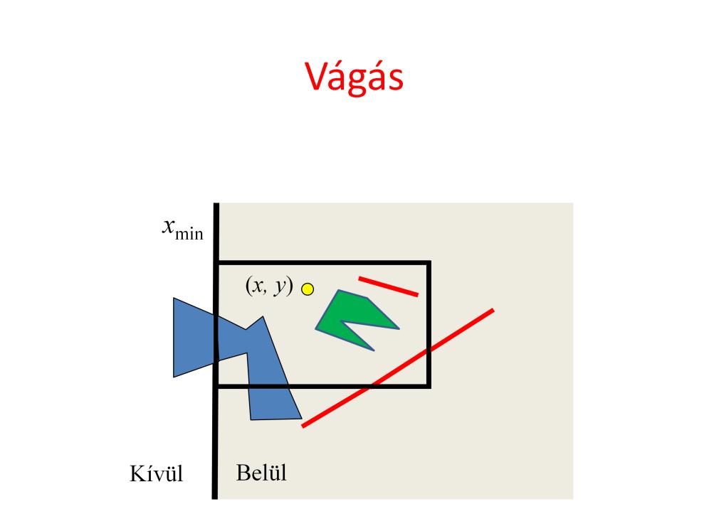
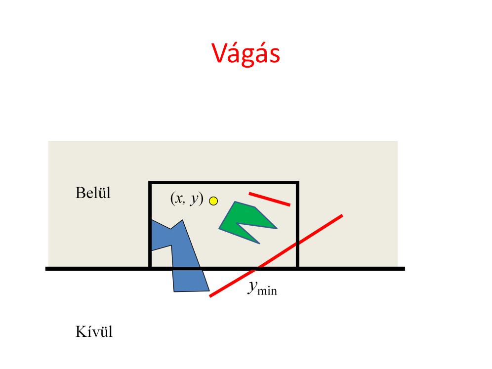
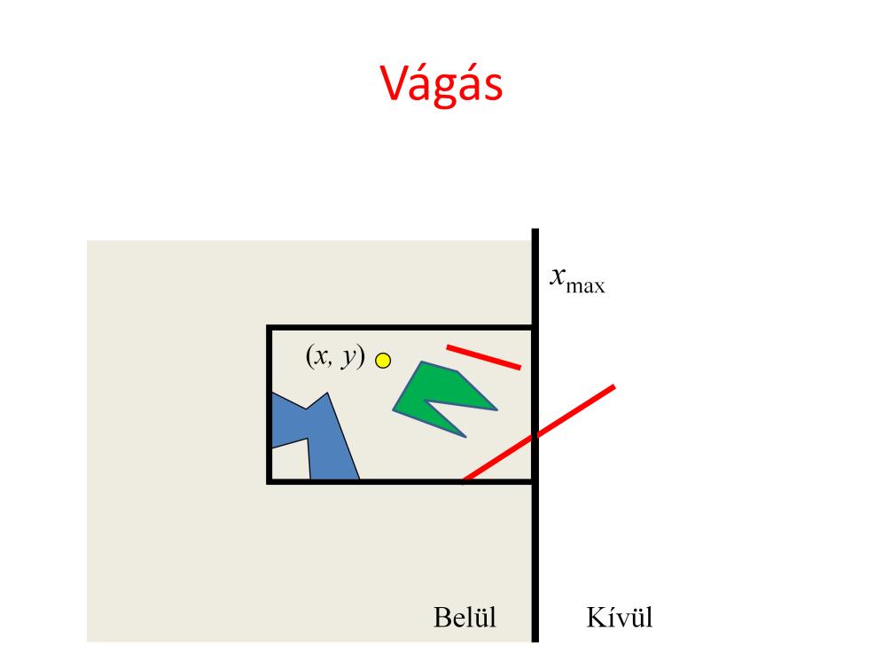
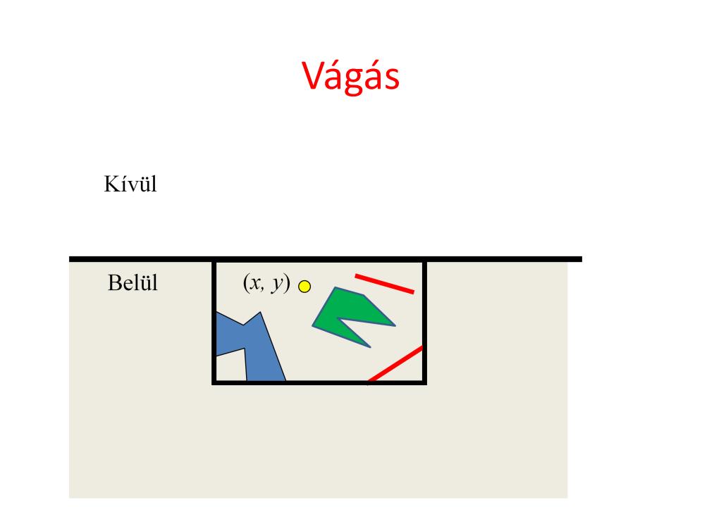
15 Clipping is executed usually in normalized device space where x,y must be between -1 and 1. To be general, we denote the limits by xmin, xmax A point is preserved by clipping if it satisfies x > x min = -1, x < x max = +1, y > y min = -1, y < y max = +1. Let us realize that each of these inequalities is a clipping condition for a half-plane. A point is inside the clipping rectangle if it is inside all four half planes since the clipping rectangle is the intersection of the half planes. This concept is very useful when line segments or polygons are clipped since testing whether or not the two endpoints of line segment or vertices of a polygon are outside the clipping rectangle cannot help to decide whether there is an inner part of the primitive.
16
17
18
19
20 Let us consider a line segment and clipping on a single half plane. If both endpoints are inside, then the complete line segment is inside since the inner region, the half plane, is convex. If both endpoints are outside, then the line segment is completely outside, since the outer region is also convex. If one endpoint is inside while the other is outside, then the intersection of the line segment and the clipping line is calculated, and the outer point is replaced by the intersection.

21 Polygon clipping is traced back to line clipping. We consider the edges of the polygon one-by-one. If both endpoints are in, the edge will also be part of the clipped polygon. If both of them are out, the edge is ignored. If one is in and the other is out, the inner part of the segment is computed and added as an edge of the clipped polygon. The input of this implementation is an array of vertices p and number of points n. The output is an array of vertices q and number of vertices m. Usually, we can assume that the ith edge has endpoints p[i] and p[i+1]. However, the last edge is an exception since its endpoints are p[n-1] and p[0].

22 The transformation from normalized device space to screen space is a scaling and a translation. This transformation is executed by the fixed function stage of the GPU. With glviewport, the parameters of the transformation can be supplied.
23 Before starting the discussion of rasterization it is worth looking at the pipeline and realizing that rasterization uses a different data element, the pixel, while phases discussed so far work with geometric primitives. A primitive may be converted to many pixels, thus the performance requirements become crucial at this stage. In order to maintain real-time frame rates, the process should output a new pixel in every few nanoseconds. It means that only those algorithms are acceptable that can deliver such performance.
24 Line drawing should provide the illusion of a line segment by coloring a few pixels. A line is thin and connected, so pixels should touch each other, should not cover unnecessary wide area and should be close to the geometric line. If the slope of the line is moderate, i.e. x is the faster growing coordinate, then it means that in every column exactly one pixel should be drawn (connected but thin), that one where the pixel center is closest to the geometric line. The line drawing algorithm iterates on the columns, and in a single column it finds the coordinate of the geometric line and finally obtains the closest pixel, which is drawn. This works, but a floating point multiplication, addition and a rounding operation is needed in a single cycle, which is too much for a few nanoseconds. So we modify this algorithm preserving its functionality but getting rid of the complicated operations.
25 The algorithm transformation is based on the incremental concept, which realizes that a linear function (the explicit equation of the line) is evaluated for an incremented X coordinate. So when X is taken, we already have the Y coordinate for X-1. The fact is that it is easier to compute Y(X) from its previous value than from X. The increment is m, the slope of the line, thus a single addition is enough to evaluate the line equation. This single addition can be made faster if we used fixed point number representation and not floating point format. As these numbers are non integers (m is less than 1), the fixed point representation should use fractional bits as well. It means that an integer stores the Tth power of 2 multiple of the non-integer value. Such values can be added as two integers. The number of fractional bits can be determined from the requirement that even the longest iteration must be correct. If the number of fractional bits is T, the error caused by the finite fractional part is 2^{-T} in a single addition. If errors are accumulated, the total error in the worst case is N 2^{-T} where N is the number of additions. N is the linear resolution of the screen, e.g In screen space the unit is the pixel, so the line will be correctly drawn if the total error is less than 1. It means that T=10, for example, satisfies all requirements. The line drawing algorithm based on the incremental concepts is as follows. First the slope of the line is computed. The y value is set according to the end point. This y stores the precise location of the line for a given x, so it is non integer. In a for cycle, the closest
26 integer is found, the pixel is written, and according to the incremental concept the new y values for the next column is obtained by a single addition. Rounding can be replaced by simple truncation if 0.5 is added to the y value. If fixed point representation is used, we shift m and y by T number of bits and rounding ignores the low T bits.
27 This algorithm can be implemented in hardware with a simple counter that generates increasing x values for every clock cycle. For y we use a register that stores both its fractional and integer parts. The y coordinate is incremented by m for every clock cycle.
28 For triangle rasterization, we need to find those pixels that are inside the triangle and color them. The search is done along horizontal lines of constant y coordinate. These lines are called scan lines and rasterization as scan conversion. For a single scan line, the triangle edges are intersected with the scan line and pixels are drawn between the minimum and maximum x coordinates. The incremental principle can also be applied to determine scan-line and edge intersections. Note that while y is incremented by 1, the x coordinate of the intersection grows with the inverse slope of the line, which is constant for the whole edge, and thus should be computed only once. Again, we have an algorithm that uses just increments and integer additions.

29 Rasterization has selected those pixels that belong to an object. The only remaining task is to obtain a color and write into the selected pixel. There are different options to find the color. It can be uniform for all points. Colors or any property from which the color is computed can be assigned to the vertices. Then the colors of internal pixels are generated by interpolation. Finally, we can also define the object vertices on a pattern image, called texture. The pattern is then mapped or wallpapered onto the object.
. Linear interpolation means that R is a linear function of pixel coordinates X, Y.")
30 The crucial problem is then the interpolation of the color, other property or texture coordinates for internal pixels. This interpolation must be fast as we have just a few nanoseconds for each pixel. Let us denote the interpolated property by R (it can be the red intensity or anything else). Linear interpolation means that R is a linear function of pixel coordinates X, Y. This linear function evaluation would require two multiplications and two additions. This can be reduced to a single addition if we use the incremental concept and focus on the difference between the R values of the current and previous pixels in this scanline.
31 Such an incremental algorithm is easy to be implemented directly in hardware. A counter increments its value to generate coordinate X for every clock cycle. A register that stores the actual R coordinate in fixed point, non-integer format (note that increment a is usually not an integer). This register is updated with the sum of its previous value and a for every clock cycle.

32 The final problem is how R increment a is calculated. One way of determining it is to satisfy the interpolation constraints at the three vertices. The other way is based on the recognition that we work with the plane equation where X,Y,R coordinates are multiplied by the coordinates of the plane s normal. The normal vector, in turn, can be calculated as a cross product of the edge vectors.
33 2D texture mapping can be imagined as wallpapering. We have a wallpaper that defines the image or the function of a given material property. This image is defined in texture space as a unit rectangle. The wallpapering process will cover the 3D surface with this image. This usually implies the distortion of the texture image. To execute texturing, we have to find a correspondence between the region and the 2D texture space. After tessellation, the region is a triangle mesh, so for each triangle, we have to identify a 2D texture space triangle, which will be painted onto the model triangle. The definition of this correspondence is called parameterization. A triangle can be parameterized with an affine transformation (x,y are linear functions of u, v). Screen space coordinates are obtained with affine transformation from x,y. Thus the mapping between texture space and screen space is also an affine linear transformation: The triangle is rasterized in screen space. When a pixel is processed, texture coordinate pair u,v must be determined from pixel coordinates X,Y.

34 Rasterization visits pixels inside the projection of the triangle and maps the center of the pixel from screen space to texture space to look up the texture color. This mapping will result in a point that is in between the texel centers. More importantly, this mapping may be a magnification, which means that a single step in screen space results in a larger step in texture space, so we may skip texels, and the result will be a mess or noise. From signal processing point of view, in this case, the texture is a high frequency signal which is sampled too rarely, resulting in sampling artifacts.

35 In case of oversampling or undersampling artifacts occur.

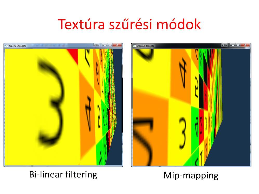
36 The solution for such sampling problems is filtering. Instead of mapping just the center of the pixel, the complete pixel rectangle must be mapped to texture space at least approximately, and the average of texels in this region should be returned as a color. However, it would be two time consuming. One efficient approximation is to prepare the texture not only in its original resolution, but also in half resolution, quarter resolution, etc. where a texel represents the average color of a square of the original texel. During rasterization, OpenGL estimates the magnification factor, and looks up the appropriate version of filtered, downsample texture. The collection of the original and downsampled textures is called mip-map.
37 If we do not like to prepare our texture with reduced resolution, there is another simpler filtering scheme. When a pixel center is mapped to texture space, not only the closest texel is obtained but the four closest ones, and the filtered color is computed as the bi-linear interpolation of their colors. The filtering method can be set separately when the pixel to texture space is a magnification or when it is a minification.
38
39
CSE528 Computer Graphics: Theory, Algorithms, and Applications
 CSE528 Computer Graphics: Theory, Algorithms, and Applications Hong Qin Stony Brook University (SUNY at Stony Brook) Stony Brook, New York 11794-2424 Tel: (631)632-845; Fax: (631)632-8334 qin@cs.stonybrook.edu
Rendering. Converting a 3D scene to a 2D image. Camera. Light. Rendering. View Plane
 Rendering Pipeline Rendering Converting a 3D scene to a 2D image Rendering Light Camera 3D Model View Plane Rendering Converting a 3D scene to a 2D image Basic rendering tasks: Modeling: creating the world
CSE328 Fundamentals of Computer Graphics
 CSE328 Fundamentals of Computer Graphics Hong Qin State University of New York at Stony Brook (Stony Brook University) Stony Brook, New York 794--44 Tel: (63)632-845; Fax: (63)632-8334 qin@cs.sunysb.edu
CS 130 Final. Fall 2015
 CS 130 Final Fall 2015 Name Student ID Signature You may not ask any questions during the test. If you believe that there is something wrong with a question, write down what you think the question is trying
2D Graphics Primitives II. Additional issues in scan converting lines. 1)Endpoint order. Want algorithms to draw the same pixels for each line
Endpoint order. Want algorithms to draw the same pixels for each line") walters@buffalo.edu CSE 480/580 Lecture 8 Slide 1 2D Graphics Primitives II Additional issues in scan converting lines 1)Endpoint order Want algorithms to draw the same pixels for each line How handle?
walters@buffalo.edu CSE 480/580 Lecture 8 Slide 1 2D Graphics Primitives II Additional issues in scan converting lines 1)Endpoint order Want algorithms to draw the same pixels for each line How handle?
Chapter 8: Implementation- Clipping and Rasterization
 Chapter 8: Implementation- Clipping and Rasterization Clipping Fundamentals Cohen-Sutherland Parametric Polygons Circles and Curves Text Basic Concepts: The purpose of clipping is to remove objects or
COMP30019 Graphics and Interaction Scan Converting Polygons and Lines
 COMP30019 Graphics and Interaction Scan Converting Polygons and Lines Department of Computer Science and Software Engineering The Lecture outline Introduction Scan conversion Scan-line algorithm Edge coherence
Computer Graphics. - Rasterization - Philipp Slusallek
 Computer Graphics - Rasterization - Philipp Slusallek Rasterization Definition Given some geometry (point, 2D line, circle, triangle, polygon, ), specify which pixels of a raster display each primitive
3D Rendering Pipeline (for direct illumination)
") Clipping 3D Rendering Pipeline (for direct illumination) 3D Primitives 3D Modeling Coordinates Modeling Transformation Lighting 3D Camera Coordinates Projection Transformation Clipping 2D Screen Coordinates
Clipping 3D Rendering Pipeline (for direct illumination) 3D Primitives 3D Modeling Coordinates Modeling Transformation Lighting 3D Camera Coordinates Projection Transformation Clipping 2D Screen Coordinates
521493S Computer Graphics Exercise 1 (Chapters 1-3)
") 521493S Computer Graphics Exercise 1 (Chapters 1-3) 1. Consider the clipping of a line segment defined by the latter s two endpoints (x 1, y 1 ) and (x 2, y 2 ) in two dimensions against a rectangular
521493S Computer Graphics Exercise 1 (Chapters 1-3) 1. Consider the clipping of a line segment defined by the latter s two endpoints (x 1, y 1 ) and (x 2, y 2 ) in two dimensions against a rectangular
Graphics (Output) Primitives. Chapters 3 & 4
 Primitives. Chapters 3 & 4") Graphics (Output) Primitives Chapters 3 & 4 Graphic Output and Input Pipeline Scan conversion converts primitives such as lines, circles, etc. into pixel values geometric description a finite scene area
Graphics (Output) Primitives Chapters 3 & 4 Graphic Output and Input Pipeline Scan conversion converts primitives such as lines, circles, etc. into pixel values geometric description a finite scene area
From Vertices to Fragments: Rasterization. Reading Assignment: Chapter 7. Special memory where pixel colors are stored.
 From Vertices to Fragments: Rasterization Reading Assignment: Chapter 7 Frame Buffer Special memory where pixel colors are stored. System Bus CPU Main Memory Graphics Card -- Graphics Processing Unit (GPU)
CSCI 4620/8626. Coordinate Reference Frames
 CSCI 4620/8626 Computer Graphics Graphics Output Primitives Last update: 2014-02-03 Coordinate Reference Frames To describe a picture, the world-coordinate reference frame (2D or 3D) must be selected.
Last class. A vertex (w x, w y, w z, w) - clipping is in the - windowing and viewport normalized view volume if: - scan conversion/ rasterization
 - clipping is in the - windowing and viewport normalized view volume if: - scan conversion/ rasterization") Lecture 6 Last class Last lecture (clip coordinates): A vertex (w x, w y, w z, w) - clipping is in the - windowing and viewport normalized view volume if: - scan conversion/ rasterization normalized view
Lecture 6 Last class Last lecture (clip coordinates): A vertex (w x, w y, w z, w) - clipping is in the - windowing and viewport normalized view volume if: - scan conversion/ rasterization normalized view
CS452/552; EE465/505. Clipping & Scan Conversion
 CS452/552; EE465/505 Clipping & Scan Conversion 3-31 15 Outline! From Geometry to Pixels: Overview Clipping (continued) Scan conversion Read: Angel, Chapter 8, 8.1-8.9 Project#1 due: this week Lab4 due:
Texture Mapping. Texture (images) lecture 16. Texture mapping Aliasing (and anti-aliasing) Adding texture improves realism.
 lecture 16. Texture mapping Aliasing (and anti-aliasing) Adding texture improves realism.") lecture 16 Texture mapping Aliasing (and anti-aliasing) Texture (images) Texture Mapping Q: Why do we need texture mapping? A: Because objects look fake and boring without it. Adding texture improves realism.
lecture 16 Texture mapping Aliasing (and anti-aliasing) Texture (images) Texture Mapping Q: Why do we need texture mapping? A: Because objects look fake and boring without it. Adding texture improves realism.
lecture 16 Texture mapping Aliasing (and anti-aliasing)
") lecture 16 Texture mapping Aliasing (and anti-aliasing) Texture (images) Texture Mapping Q: Why do we need texture mapping? A: Because objects look fake and boring without it. Adding texture improves realism.
lecture 16 Texture mapping Aliasing (and anti-aliasing) Texture (images) Texture Mapping Q: Why do we need texture mapping? A: Because objects look fake and boring without it. Adding texture improves realism.
OpenGL Graphics System. 2D Graphics Primitives. Drawing 2D Graphics Primitives. 2D Graphics Primitives. Mathematical 2D Primitives.
 D Graphics Primitives Eye sees Displays - CRT/LCD Frame buffer - Addressable pixel array (D) Graphics processor s main function is to map application model (D) by projection on to D primitives: points,
Geometric transformations assign a point to a point, so it is a point valued function of points. Geometric transformation may destroy the equation
 Geometric transformations assign a point to a point, so it is a point valued function of points. Geometric transformation may destroy the equation and the type of an object. Even simple scaling turns a
From Vertices To Fragments-1
 From Vertices To Fragments-1 1 Objectives Clipping Line-segment clipping polygon clipping 2 Overview At end of the geometric pipeline, vertices have been assembled into primitives Must clip out primitives
Computer Graphics. Attributes of Graphics Primitives. Somsak Walairacht, Computer Engineering, KMITL 1
 Computer Graphics Chapter 4 Attributes of Graphics Primitives Somsak Walairacht, Computer Engineering, KMITL 1 Outline OpenGL State Variables Point Attributes t Line Attributes Fill-Area Attributes Scan-Line
CS 465 Program 4: Modeller
 CS 465 Program 4: Modeller out: 30 October 2004 due: 16 November 2004 1 Introduction In this assignment you will work on a simple 3D modelling system that uses simple primitives and curved surfaces organized
Institutionen för systemteknik
 Code: Day: Lokal: M7002E 19 March E1026 Institutionen för systemteknik Examination in: M7002E, Computer Graphics and Virtual Environments Number of sections: 7 Max. score: 100 (normally 60 is required
Computer Graphics. Chapter 4 Attributes of Graphics Primitives. Somsak Walairacht, Computer Engineering, KMITL 1
 Computer Graphics Chapter 4 Attributes of Graphics Primitives Somsak Walairacht, Computer Engineering, KMITL 1 Outline OpenGL State Variables Point Attributes Line Attributes Fill-Area Attributes Scan-Line
Two-Dimensional Viewing. Chapter 6
 Two-Dimensional Viewing Chapter 6 Viewing Pipeline Two-Dimensional Viewing Two dimensional viewing transformation From world coordinate scene description to device (screen) coordinates Normalization and
Graphics Pipeline 2D Geometric Transformations
 Graphics Pipeline 2D Geometric Transformations CS 4620 Lecture 8 1 Plane projection in drawing Albrecht Dürer 2 Plane projection in drawing source unknown 3 Rasterizing triangles Summary 1 evaluation of
0. Introduction: What is Computer Graphics? 1. Basics of scan conversion (line drawing) 2. Representing 2D curves
 2. Representing 2D curves") CSC 418/2504: Computer Graphics Course web site (includes course information sheet): http://www.dgp.toronto.edu/~elf Instructor: Eugene Fiume Office: BA 5266 Phone: 416 978 5472 (not a reliable way) Email:
CSC 418/2504: Computer Graphics Course web site (includes course information sheet): http://www.dgp.toronto.edu/~elf Instructor: Eugene Fiume Office: BA 5266 Phone: 416 978 5472 (not a reliable way) Email:
Clipping and Scan Conversion
 15-462 Computer Graphics I Lecture 14 Clipping and Scan Conversion Line Clipping Polygon Clipping Clipping in Three Dimensions Scan Conversion (Rasterization) [Angel 7.3-7.6, 7.8-7.9] March 19, 2002 Frank
CHAPTER 1 Graphics Systems and Models 3
 ?????? 1 CHAPTER 1 Graphics Systems and Models 3 1.1 Applications of Computer Graphics 4 1.1.1 Display of Information............. 4 1.1.2 Design.................... 5 1.1.3 Simulation and Animation...........
2D Image Synthesis. 2D image synthesis. Raster graphics systems. Modeling transformation. Vectorization. u x u y 0. o x o y 1
 General scheme of a 2D CG application 2D Image Synthesis Balázs Csébfalvi modeling image synthesis Virtual world model world defined in a 2D plane Department of Control Engineering and Information Technology
Renderer Implementation: Basics and Clipping. Overview. Preliminaries. David Carr Virtual Environments, Fundamentals Spring 2005
 INSTITUTIONEN FÖR SYSTEMTEKNIK LULEÅ TEKNISKA UNIVERSITET Renderer Implementation: Basics and Clipping David Carr Virtual Environments, Fundamentals Spring 2005 Feb-28-05 SMM009, Basics and Clipping 1
CS488 2D Graphics. Luc RENAMBOT
 CS488 2D Graphics Luc RENAMBOT 1 Topics Last time, hardware and frame buffer Now, how lines and polygons are drawn in the frame buffer. Then, how 2D and 3D models drawing into the frame buffer Then, more
Chapter 3. Sukhwinder Singh
 Chapter 3 Sukhwinder Singh PIXEL ADDRESSING AND OBJECT GEOMETRY Object descriptions are given in a world reference frame, chosen to suit a particular application, and input world coordinates are ultimately
Direct Rendering of Trimmed NURBS Surfaces
 Direct Rendering of Trimmed NURBS Surfaces Hardware Graphics Pipeline 2/ 81 Hardware Graphics Pipeline GPU Video Memory CPU Vertex Processor Raster Unit Fragment Processor Render Target Screen Extended
Einführung in Visual Computing
 Einführung in Visual Computing 186.822 Rasterization Werner Purgathofer Rasterization in the Rendering Pipeline scene objects in object space transformed vertices in clip space scene in normalized device
CSE528 Computer Graphics: Theory, Algorithms, and Applications
 CSE528 Computer Graphics: Theory, Algorithms, and Applications Hong Qin State University of New York at Stony Brook (Stony Brook University) Stony Brook, New York 11794--4400 Tel: (631)632-8450; Fax: (631)632-8334
CS 4620 Midterm, March 21, 2017
 CS 460 Midterm, March 1, 017 This 90-minute exam has 4 questions worth a total of 100 points. Use the back of the pages if you need more space. Academic Integrity is expected of all students of Cornell
RASTERIZING POLYGONS IN IMAGE SPACE
 On-Line Computer Graphics Notes RASTERIZING POLYGONS IN IMAGE SPACE Kenneth I. Joy Visualization and Graphics Research Group Department of Computer Science University of California, Davis A fundamental
Graphics and Interaction Rendering pipeline & object modelling
 433-324 Graphics and Interaction Rendering pipeline & object modelling Department of Computer Science and Software Engineering The Lecture outline Introduction to Modelling Polygonal geometry The rendering
CS 4204 Computer Graphics
 CS 4204 Computer Graphics 3D Viewing and Projection Yong Cao Virginia Tech Objective We will develop methods to camera through scenes. We will develop mathematical tools to handle perspective projection.
The Traditional Graphics Pipeline
 Last Time? The Traditional Graphics Pipeline Participating Media Measuring BRDFs 3D Digitizing & Scattering BSSRDFs Monte Carlo Simulation Dipole Approximation Today Ray Casting / Tracing Advantages? Ray
S U N G - E U I YO O N, K A I S T R E N D E R I N G F R E E LY A VA I L A B L E O N T H E I N T E R N E T
 S U N G - E U I YO O N, K A I S T R E N D E R I N G F R E E LY A VA I L A B L E O N T H E I N T E R N E T Copyright 2018 Sung-eui Yoon, KAIST freely available on the internet http://sglab.kaist.ac.kr/~sungeui/render
3D Polygon Rendering. Many applications use rendering of 3D polygons with direct illumination
 Rendering Pipeline 3D Polygon Rendering Many applications use rendering of 3D polygons with direct illumination 3D Polygon Rendering What steps are necessary to utilize spatial coherence while drawing
The goal is the definition of points with numbers and primitives with equations or functions. The definition of points with numbers requires a
 The goal is the definition of points with numbers and primitives with equations or functions. The definition of points with numbers requires a coordinate system and then the measuring of the point with
CS602 Midterm Subjective Solved with Reference By WELL WISHER (Aqua Leo)
") CS602 Midterm Subjective Solved with Reference By WELL WISHER (Aqua Leo) www.vucybarien.com Question No: 1 What are the two focusing methods in CRT? Explain briefly. Page no : 26 1. Electrostatic focusing
CS602 Midterm Subjective Solved with Reference By WELL WISHER (Aqua Leo) www.vucybarien.com Question No: 1 What are the two focusing methods in CRT? Explain briefly. Page no : 26 1. Electrostatic focusing
Topics. From vertices to fragments
 Topics From vertices to fragments From Vertices to Fragments Assign a color to every pixel Pass every object through the system Required tasks: Modeling Geometric processing Rasterization Fragment processing
Announcements. Midterms graded back at the end of class Help session on Assignment 3 for last ~20 minutes of class. Computer Graphics
 Announcements Midterms graded back at the end of class Help session on Assignment 3 for last ~20 minutes of class 1 Scan Conversion Overview of Rendering Scan Conversion Drawing Lines Drawing Polygons
The Traditional Graphics Pipeline
 Final Projects Proposals due Thursday 4/8 Proposed project summary At least 3 related papers (read & summarized) Description of series of test cases Timeline & initial task assignment The Traditional Graphics
CSCI 4620/8626. Computer Graphics Clipping Algorithms (Chapter 8-5 )
") CSCI 4620/8626 Computer Graphics Clipping Algorithms (Chapter 8-5 ) Last update: 2016-03-15 Clipping Algorithms A clipping algorithm is any procedure that eliminates those portions of a picture outside
CSCI 4620/8626 Computer Graphics Clipping Algorithms (Chapter 8-5 ) Last update: 2016-03-15 Clipping Algorithms A clipping algorithm is any procedure that eliminates those portions of a picture outside
Surface shading: lights and rasterization. Computer Graphics CSE 167 Lecture 6
 Surface shading: lights and rasterization Computer Graphics CSE 167 Lecture 6 CSE 167: Computer Graphics Surface shading Materials Lights Rasterization 2 Scene data Rendering pipeline Modeling and viewing
Texture Mapping. Michael Kazhdan ( /467) HB Ch. 14.8,14.9 FvDFH Ch. 16.3, , 16.6
 HB Ch. 14.8,14.9 FvDFH Ch. 16.3, , 16.6") Texture Mapping Michael Kazhdan (61.457/467) HB Ch. 14.8,14.9 FvDFH Ch. 16.3, 16.4.5, 16.6 Textures We know how to go from this to this J. Birn Textures But what about this to this? J. Birn Textures How
Texture Mapping Michael Kazhdan (61.457/467) HB Ch. 14.8,14.9 FvDFH Ch. 16.3, 16.4.5, 16.6 Textures We know how to go from this to this J. Birn Textures But what about this to this? J. Birn Textures How
CMSC427 Transformations II: Viewing. Credit: some slides from Dr. Zwicker
 CMSC427 Transformations II: Viewing Credit: some slides from Dr. Zwicker What next? GIVEN THE TOOLS OF The standard rigid and affine transformations Their representation with matrices and homogeneous coordinates
The Traditional Graphics Pipeline
 Last Time? The Traditional Graphics Pipeline Reading for Today A Practical Model for Subsurface Light Transport, Jensen, Marschner, Levoy, & Hanrahan, SIGGRAPH 2001 Participating Media Measuring BRDFs
Adaptive Point Cloud Rendering
 1 Adaptive Point Cloud Rendering Project Plan Final Group: May13-11 Christopher Jeffers Eric Jensen Joel Rausch Client: Siemens PLM Software Client Contact: Michael Carter Adviser: Simanta Mitra 4/29/13
Clipping & Culling. Lecture 11 Spring Trivial Rejection Outcode Clipping Plane-at-a-time Clipping Backface Culling
 Clipping & Culling Trivial Rejection Outcode Clipping Plane-at-a-time Clipping Backface Culling Lecture 11 Spring 2015 What is Clipping? Clipping is a procedure for spatially partitioning geometric primitives,
Barycentric Coordinates and Parameterization
 Barycentric Coordinates and Parameterization Center of Mass Geometric center of object Center of Mass Geometric center of object Object can be balanced on CoM How to calculate? Finding the Center of Mass
COMP30019 Graphics and Interaction Rendering pipeline & object modelling
 COMP30019 Graphics and Interaction Rendering pipeline & object modelling Department of Computer Science and Software Engineering The Lecture outline Introduction to Modelling Polygonal geometry The rendering
Lecture outline. COMP30019 Graphics and Interaction Rendering pipeline & object modelling. Introduction to modelling
 Lecture outline COMP30019 Graphics and Interaction Rendering pipeline & object modelling Department of Computer Science and Software Engineering The Introduction to Modelling Polygonal geometry The rendering
CSE 167: Lecture #5: Rasterization. Jürgen P. Schulze, Ph.D. University of California, San Diego Fall Quarter 2012
 CSE 167: Introduction to Computer Graphics Lecture #5: Rasterization Jürgen P. Schulze, Ph.D. University of California, San Diego Fall Quarter 2012 Announcements Homework project #2 due this Friday, October
EF432. Introduction to spagetti and meatballs
 EF432 Introduction to spagetti and meatballs CSC 418/2504: Computer Graphics Course web site (includes course information sheet): http://www.dgp.toronto.edu/~karan/courses/418/fall2015 Instructor: Karan
Pipeline and Rasterization. COMP770 Fall 2011
 Pipeline and Rasterization COMP770 Fall 2011 1 The graphics pipeline The standard approach to object-order graphics Many versions exist software, e.g. Pixar s REYES architecture many options for quality
Realtime 3D Computer Graphics Virtual Reality
 Realtime 3D Computer Graphics Virtual Reality From Vertices to Fragments Overview Overall goal recapitulation: Input: World description, e.g., set of vertices and states for objects, attributes, camera,
Computer Graphics Geometry and Transform
 ! Computer Graphics 2014! 5. Geometry and Transform Hongxin Zhang State Key Lab of CAD&CG, Zhejiang University 2014-10-11! Today outline Triangle rasterization Basic vector algebra ~ geometry! Antialiasing
Scan Conversion. Drawing Lines Drawing Circles
 Scan Conversion Drawing Lines Drawing Circles 1 How to Draw This? 2 Start From Simple How to draw a line: y(x) = mx + b? 3 Scan Conversion, a.k.a. Rasterization Ideal Picture Raster Representation Scan
Today. Rendering pipeline. Rendering pipeline. Object vs. Image order. Rendering engine Rendering engine (jtrt) Computergrafik. Rendering pipeline
 Computergrafik. Rendering pipeline") Computergrafik Today Rendering pipeline s View volumes, clipping Viewport Matthias Zwicker Universität Bern Herbst 2008 Rendering pipeline Rendering pipeline Hardware & software that draws 3D scenes on
Computergrafik Today Rendering pipeline s View volumes, clipping Viewport Matthias Zwicker Universität Bern Herbst 2008 Rendering pipeline Rendering pipeline Hardware & software that draws 3D scenes on
Polygon Filling. Can write frame buffer one word at time rather than one bit. 2/3/2000 CS 4/57101 Lecture 6 1
 Polygon Filling 2 parts to task which pixels to fill what to fill them with First consider filling unclipped primitives with solid color Which pixels to fill consider scan lines that intersect primitive
Computer Graphics. The Two-Dimensional Viewing. Somsak Walairacht, Computer Engineering, KMITL
 Computer Graphics Chapter 6 The Two-Dimensional Viewing Somsak Walairacht, Computer Engineering, KMITL Outline The Two-Dimensional Viewing Pipeline The Clipping Window Normalization and Viewport Transformations
Computer Graphics 7 - Rasterisation
 Computer Graphics 7 - Rasterisation Tom Thorne Slides courtesy of Taku Komura www.inf.ed.ac.uk/teaching/courses/cg Overview Line rasterisation Polygon rasterisation Mean value coordinates Decomposing polygons
Rasterization. COMP 575/770 Spring 2013
 Rasterization COMP 575/770 Spring 2013 The Rasterization Pipeline you are here APPLICATION COMMAND STREAM 3D transformations; shading VERTEX PROCESSING TRANSFORMED GEOMETRY conversion of primitives to
CS 130 Exam I. Fall 2015
 S 3 Exam I Fall 25 Name Student ID Signature You may not ask any questions during the test. If you believe that there is something wrong with a question, write down what you think the question is trying
coding of various parts showing different features, the possibility of rotation or of hiding covering parts of the object's surface to gain an insight
 Three-Dimensional Object Reconstruction from Layered Spatial Data Michael Dangl and Robert Sablatnig Vienna University of Technology, Institute of Computer Aided Automation, Pattern Recognition and Image
Raster Displays and Scan Conversion. Computer Graphics, CSCD18 Fall 2008 Instructor: Leonid Sigal
 Raster Displays and Scan Conversion Computer Graphics, CSCD18 Fall 28 Instructor: Leonid Sigal Rater Displays Screen is represented by 2D array of locations called piels y Rater Displays Screen is represented
INTRODUCTION TO COMPUTER GRAPHICS. It looks like a matrix Sort of. Viewing III. Projection in Practice. Bin Sheng 10/11/ / 52
 cs337 It looks like a matrix Sort of Viewing III Projection in Practice / 52 cs337 Arbitrary 3D views Now that we have familiarity with terms we can say that these view volumes/frusta can be specified
Line Drawing. Introduction to Computer Graphics Torsten Möller / Mike Phillips. Machiraju/Zhang/Möller
 Line Drawing Introduction to Computer Graphics Torsten Möller / Mike Phillips Rendering Pipeline Hardware Modelling Transform Visibility Illumination + Shading Perception, Color Interaction Texture/ Realism
FROM VERTICES TO FRAGMENTS. Lecture 5 Comp3080 Computer Graphics HKBU
 FROM VERTICES TO FRAGMENTS Lecture 5 Comp3080 Computer Graphics HKBU OBJECTIVES Introduce basic implementation strategies Clipping Scan conversion OCTOBER 9, 2011 2 OVERVIEW At end of the geometric pipeline,
COMP371 COMPUTER GRAPHICS
 COMP371 COMPUTER GRAPHICS LECTURE 14 RASTERIZATION 1 Lecture Overview Review of last class Line Scan conversion Polygon Scan conversion Antialiasing 2 Rasterization The raster display is a matrix of picture
Computer Graphics. Texture Filtering & Sampling Theory. Hendrik Lensch. Computer Graphics WS07/08 Texturing
 Computer Graphics Texture Filtering & Sampling Theory Hendrik Lensch Overview Last time Texture Parameterization Procedural Shading Today Texturing Filtering 2D Texture Mapping Forward mapping Object surface
1 Introduction to Graphics
 1 1.1 Raster Displays The screen is represented by a 2D array of locations called pixels. Zooming in on an image made up of pixels The convention in these notes will follow that of OpenGL, placing the
Triangle Rasterization
 Triangle Rasterization Computer Graphics COMP 770 (236) Spring 2007 Instructor: Brandon Lloyd 2/07/07 1 From last time Lines and planes Culling View frustum culling Back-face culling Occlusion culling
CS 112 The Rendering Pipeline. Slide 1
 CS 112 The Rendering Pipeline Slide 1 Rendering Pipeline n Input 3D Object/Scene Representation n Output An image of the input object/scene n Stages (for POLYGON pipeline) n Model view Transformation n
C P S C 314 S H A D E R S, O P E N G L, & J S RENDERING PIPELINE. Mikhail Bessmeltsev
 C P S C 314 S H A D E R S, O P E N G L, & J S RENDERING PIPELINE UGRAD.CS.UBC.C A/~CS314 Mikhail Bessmeltsev 1 WHAT IS RENDERING? Generating image from a 3D scene 2 WHAT IS RENDERING? Generating image
UNIT 2 GRAPHIC PRIMITIVES
 UNIT 2 GRAPHIC PRIMITIVES Structure Page Nos. 2.1 Introduction 46 2.2 Objectives 46 2.3 Points and Lines 46 2.4 Line Generation Algorithms 48 2.4.1 DDA Algorithm 49 2.4.2 Bresenhams Line Generation Algorithm
For each question, indicate whether the statement is true or false by circling T or F, respectively.
 True/False For each question, indicate whether the statement is true or false by circling T or F, respectively. 1. (T/F) Rasterization occurs before vertex transformation in the graphics pipeline. 2. (T/F)
Clipping. CSC 7443: Scientific Information Visualization
 Clipping Clipping to See Inside Obscuring critical information contained in a volume data Contour displays show only exterior visible surfaces Isosurfaces can hide other isosurfaces Other displays can
CS602 MCQ,s for midterm paper with reference solved by Shahid
 #1 Rotating a point requires The coordinates for the point The rotation angles Both of above Page No 175 None of above #2 In Trimetric the direction of projection makes unequal angle with the three principal
Rasterization. CS 4620 Lecture Kavita Bala w/ prior instructor Steve Marschner. Cornell CS4620 Fall 2015 Lecture 16
 Rasterization CS 4620 Lecture 16 1 Announcements A3 due on Thu Will send mail about grading once finalized 2 Pipeline overview you are here APPLICATION COMMAND STREAM 3D transformations; shading VERTEX
Perspective Mappings. Contents
 Perspective Mappings David Eberly, Geometric Tools, Redmond WA 98052 https://www.geometrictools.com/ This work is licensed under the Creative Commons Attribution 4.0 International License. To view a copy
CS Exam 1 Review Problems Fall 2017
 CS 45500 Exam 1 Review Problems Fall 2017 1. What is a FrameBuffer data structure? What does it contain? What does it represent? How is it used in a graphics rendering pipeline? 2. What is a Scene data
Lets assume each object has a defined colour. Hence our illumination model is looks unrealistic.
 Shading Models There are two main types of rendering that we cover, polygon rendering ray tracing Polygon rendering is used to apply illumination models to polygons, whereas ray tracing applies to arbitrary
From Ver(ces to Fragments: Rasteriza(on
 From Ver(ces to Fragments: Rasteriza(on From Ver(ces to Fragments 3D vertices vertex shader rasterizer fragment shader final pixels 2D screen fragments l determine fragments to be covered l interpolate
Tópicos de Computação Gráfica Topics in Computer Graphics 10509: Doutoramento em Engenharia Informática. Chap. 2 Rasterization.
 Tópicos de Computação Gráfica Topics in Computer Graphics 10509: Doutoramento em Engenharia Informática Chap. 2 Rasterization Rasterization Outline : Raster display technology. Basic concepts: pixel, resolution,
S U N G - E U I YO O N, K A I S T R E N D E R I N G F R E E LY A VA I L A B L E O N T H E I N T E R N E T
 S U N G - E U I YO O N, K A I S T R E N D E R I N G F R E E LY A VA I L A B L E O N T H E I N T E R N E T Copyright 2018 Sung-eui Yoon, KAIST freely available on the internet http://sglab.kaist.ac.kr/~sungeui/render
Rasterization and Graphics Hardware. Not just about fancy 3D! Rendering/Rasterization. The simplest case: Points. When do we care?
 Where does a picture come from? Rasterization and Graphics Hardware CS559 Course Notes Not for Projection November 2007, Mike Gleicher Result: image (raster) Input 2D/3D model of the world Rendering term
CS 543: Computer Graphics. Rasterization
 CS 543: Computer Graphics Rasterization Robert W. Lindeman Associate Professor Interactive Media & Game Development Department of Computer Science Worcester Polytechnic Institute gogo@wpi.edu (with lots
Review of Tuesday. ECS 175 Chapter 3: Object Representation
 Review of Tuesday We have learnt how to rasterize lines and fill polygons Colors (and other attributes) are specified at vertices Interpolation required to fill polygon with attributes 26 Review of Tuesday
The graphics pipeline. Pipeline and Rasterization. Primitives. Pipeline
 The graphics pipeline Pipeline and Rasterization CS4620 Lecture 9 The standard approach to object-order graphics Many versions exist software, e.g. Pixar s REYES architecture many options for quality and
Computer Graphics and GPGPU Programming
 Computer Graphics and GPGPU Programming Donato D Ambrosio Department of Mathematics and Computer Science and Center of Excellence for High Performace Computing Cubo 22B, University of Calabria, Rende 87036,
Rasterization. CS4620 Lecture 13
 Rasterization CS4620 Lecture 13 2014 Steve Marschner 1 The graphics pipeline The standard approach to object-order graphics Many versions exist software, e.g. Pixar s REYES architecture many options for
Texturing Theory. Overview. All it takes is for the rendered image to look right. -Jim Blinn 11/10/2018
 References: Real-Time Rendering 3 rd Edition Chapter 6 Texturing Theory All it takes is for the rendered image to look right. -Jim Blinn Overview Introduction The Texturing Pipeline Example The Projector
INTRODUCTION TO COMPUTER GRAPHICS. cs123. It looks like a matrix Sort of. Viewing III. Projection in Practice 1 / 52
 It looks like a matrix Sort of Viewing III Projection in Practice 1 / 52 Arbitrary 3D views } view volumes/frusta spec d by placement and shape } Placement: } Position (a point) } look and up vectors }