3ds Max Cottage Step 1. Always start out by setting up units: We re going with this setup as we will round everything off to one inch.
|
|
|
- Ashley Baldwin
- 5 years ago
- Views:
Transcription


1 3ds Max Cottage Step 1 Always start out by setting up units: We re going with this setup as we will round everything off to one inch.


2 File/Import the CAD drawing Be sure Files of Type is set to all formats or AutoCAD drawing:


3 Turn on Rescale and set to inches: Turn off all layers except A-wall and click OK: Look at your layers (icon in the main menu)


4 Your file will look like this: Let s save the file now to Cottage001. (File/Save and then name.) To continue Tip: For better visibility, Hit F4 for edged faces Hit J to turn off the bounding box. Select the move tool: Set these all these values to 0 to position the drawing at the center of the grid.


5 Deselect the shape by clicking on the viewport background. Make a new layer and make it active with the check mark. Name it 3d model: Activate the top viewport Zoom to fit the shape. Activate the create tab in the command panel Activate Shapes with Splines Select Rectangle


6 Turn on Snap Right click on snap Set up snap to Vertex We will start with drawing the outer perimeters of the floor or foundation. Draw a box like this:
 Right click on the rectangle and convert")

7 Name it floor-foundation in the modify tab (looks like a bending shape) Right click on the rectangle and convert to an editable spline The outer walls will have the same dimensions, so let's set that up. Right click/select clone

 Tip your")
8 Name it walls Select copy (not instance) You now have 2 shapes exactly the same, one on top of the other. One is for the walls, one is for the floor. Walls is now selected. We have the outer wall. Next we need to create the inner walls. Go to the create tab in the command panel (looks like a white selection arrow) Tip your layers should look like this:


9 Turn OFF Start New Shape. This is counter-intuitive, but it will allow us to make the inner wall as part of the entire wall thickness. You'll see as we proceed. Draw the inner walls as shown below. No windows or doors, just match these white lines. Click Yes to close spline when finished drawing. In the modifier drop-down select Extrude. Set to 9 feet:


10 Lets extrude down the foundation now. Right click in layers to select: Select Extrude from the modifiers list: It will appear too tall at first. Set the height to minus 1 6 Set another color by clicking on the color swatch:


11 Now select the Walls and we will cut an opening for the door: Make sure the Walls object is selected. Drop down the modifier list and select Edit Poly Access the Polygon sub-object level: Turn on ignore backfacing: S


12 elect the Walls and hit Alt X to view in X-Ray mode hide Floor-foundation: Important select both the back and the front of this one wall. Use the control key to select more than one object in Max. Remember to arc rotate (orbit) around the object using the middle mouse button while holding down the Alt key.) Hit F2 to see through the red selection better:


13 Using slice plane to cut a hole for the door. Enter slice plane mode by making the Slice Plane button yellow. Rotate or move the plane into position, to make a cut. Turn on angle snap first: Rotate Slice plane, move into position, and make 2 as shown:


14 Rotate slice plane for the top position and cut. Use the read out for Z as shown below to 7' Exit slice plane by hitting the slice plane button so it is no longer yellow. Delete the 2 polygons of the door: Go to the border subobject level and select the openings on each side:


15 Click on Bridge to close the sides of the door: Now lets make the door for the doorway. Turn on Snap, making sure it is set to Vertex. In the Create panel, drop down and select Doors. Draw a door, snapping to the red lines; Click in a corner and drag across to make the width, drag forward to make the thickness, click and drag up to make the height. Each time you will snap to a vertex in the walls.

16 Make choices here regarding panels and set the pivot to flip swing 30 degrees: Tip hit the Esc key once or twice to exit door creation. Let's cut holes for 4 windows next. Select the front and back of the walls. Active Slice Plane again. Rotate and move the slice plane into position for the first edge. Tip: when in the move tool, you can use relative positioning for the width. When you hit enter the slice plane will move 4 feet on the X axis. Note the the numeric box will reset to 0.


17 Now go back to absolute measuring mode. Use 7' for the top horizontal cut and 3' for the bottom cut:


18 Delete the unwanted polygons: Exit the polygon sub-object level: Tip: click on the yellow.


19 In the create tab, drop down to windows: Tip: you can turn off angle snap. Make sure Snaps toggle is on. Try a sliding window. Tip: note the creation method, which is the order you are creating the window in. Make sure you zoom in enough to see what you are snapping to. I opened my window here:


20 Now we will clone the windows. Turn off angle snap. Holding down the shift key, drag a clone to the position of the second window. Make sure you choose copy not instance. Type in 3 to make 3 windows. When you hit OK you now have 4 windows: Select the walls object and use Alt-X on the keyboard to turn off X-ray view. Vary the window opening settings:
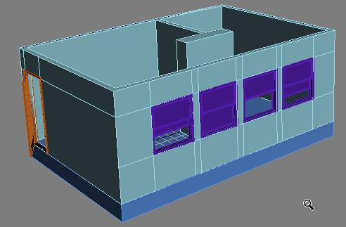
21
Walls and Windows. Here is a useful link to explore for later -- AutoCAD drawing tutorials:
 Walls and Windows Eventually we will import your CAD drawings and you will need well-constructed files which we will then use extrude, loft, and sweep, etc., in Max. Here is a useful link to explore for
1st Point. 2nd Point. hold shift & drag along Y. Splines
 Splines STEP 1: open 3DS Max _ from the Command Panel under the Create tab click on Shapes (note: shapes are really Splines) _ under Object Type click on Ellipse STEP 2: Expand the Keyboard Entry tab type
SolidWorks Intro Part 1b
 SolidWorks Intro Part 1b Dave Touretzky and Susan Finger 1. Create a new part We ll create a CAD model of the 2 ½ D key fob below to make on the laser cutter. Select File New Templates IPSpart If the SolidWorks
A Guide to Autodesk Maya 2015
 A Guide to Autodesk Maya 2015 Written by Mitchell Youngerman Table of Contents Layout of Toolbars...pg 1 Creating Objects...pg 2 Selecting & Deselecting Objects...pg 3 Changing Perspective... pg 4 Transforming
Table of Contents. KCD Terminology.2-4. KCD Dimensions KCD Toolbar KCD Top Ten Short Cuts...10
 Table of Contents KCD Terminology.2-4 KCD Dimensions...5-6 KCD Toolbar...7-9 KCD Top Ten Short Cuts......10 KCD Terminology Main KCD Screen A The Main Menu, this is where you will be able to find all the
SolidWorks 2½D Parts
 SolidWorks 2½D Parts IDeATe Laser Micro Part 1b Dave Touretzky and Susan Finger 1. Create a new part In this lab, you ll create a CAD model of the 2 ½ D key fob below to make on the laser cutter. Select
Autodesk Fusion 360: Model. Overview. Modeling techniques in Fusion 360
 Overview Modeling techniques in Fusion 360 Modeling in Fusion 360 is quite a different experience from how you would model in conventional history-based CAD software. Some users have expressed that it
Skateboard. Hanger. in the Feature Manager and click Sketch on the Context toolbar, Fig. 1. Fig. 2
 Chapter 3 Skateboard Hanger A. Sketch1 Lines. Step 1. Click File Menu > New, click Part Metric and OK. Step 2. Click Right Plane in the Feature Manager and click Sketch on the Context toolbar, Fig. 1.
Lesson 1: Creating T- Spline Forms. In Samples section of your Data Panel, browse to: Fusion 101 Training > 03 Sculpt > 03_Sculpting_Introduction.
 3.1: Sculpting Sculpting in Fusion 360 allows for the intuitive freeform creation of organic solid bodies and surfaces by leveraging the T- Splines technology. In the Sculpt Workspace, you can rapidly
EXERCISE 6: AEC OBJECTS
 EXERCISE 6: AEC OBJECTS ASSIGNMENT: In this exercise you will create a small pavilion using AEC extended objects, Doors, Windows and Stairs LEARNING OBJECTIVES: Modeling with AEC Objects Using Door, Windows,
Fixed Perimeter Rectangles Geometry Creating a Document
 Activity Overview: This activity provides the steps to create a TI-Nspire document that will be used to investigate side length and area in a rectangle with a fixed perimeter. An algebraic approach is
StickFont Editor v1.01 User Manual. Copyright 2012 NCPlot Software LLC
 StickFont Editor v1.01 User Manual Copyright 2012 NCPlot Software LLC StickFont Editor Manual Table of Contents Welcome... 1 Registering StickFont Editor... 3 Getting Started... 5 Getting Started...
Autodesk Inventor - Basics Tutorial Exercise 1
 Autodesk Inventor - Basics Tutorial Exercise 1 Launch Inventor Professional 2015 1. Start a New part. Depending on how Inventor was installed, using this icon may get you an Inch or Metric file. To be
REVIT ARCHITECTURE 2016
 Page 1 of 6 REVIT ARCHITECTURE 2016 Revit Architecture 2016: CREATE A CHAMFERED COLUMN COMPONENT About creating a chamfered column family typical to the Victorian cottage style. Add the column to your
A QUICK TOUR OF ADOBE ILLUSTRATOR CC (2018 RELEASE)
") A QUICK TOUR OF ADOBE ILLUSTRATOR CC (2018 RELEASE) Lesson overview In this interactive demonstration of Adobe Illustrator CC (2018 release), you ll get an overview of the main features of the application.
A QUICK TOUR OF ADOBE ILLUSTRATOR CC (2018 RELEASE) Lesson overview In this interactive demonstration of Adobe Illustrator CC (2018 release), you ll get an overview of the main features of the application.
Caustics - Mental Ray
 Caustics - Mental Ray (Working with real caustic generation) In this tutorial we are going to go over some advanced lighting techniques for creating realistic caustic effects. Caustics are the bent reflections
FormZ Tips created by Phil Jones, edited by Nancy Cheng, University of Oregon 11/16/05
 FormZ Tips created by Phil Jones, edited by Nancy Cheng, University of Oregon 11/16/05 window tools: 1 2 3 4 5 6 7 8 9 1 set reference plane use this to choose between standard reference planes. 2 perpendicular
Keyboard Shortcuts. Command Windows Macintosh
 S00ILCS5.qxp 3/19/2010 1:11 AM Page 477 Keyboard Shortcuts k Adobe Illustrator CS5 If a command on a menu includes a keyboard reference, known as a keyboard shortcut, to the right of the command name,
Modeling a Gear Standard Tools, Surface Tools Solid Tool View, Trackball, Show-Hide Snaps Window 1-1
 Modeling a Gear This tutorial describes how to create a toothed gear. It combines using wireframe, solid, and surface modeling together to create a part. The model was created in standard units. To begin,
Exercise Guide. Published: August MecSoft Corpotation
 VisualCAD Exercise Guide Published: August 2018 MecSoft Corpotation Copyright 1998-2018 VisualCAD 2018 Exercise Guide by Mecsoft Corporation User Notes: Contents 2 Table of Contents About this Guide 4
An Approach to Content Creation for Trainz
 An Approach to Content Creation for Trainz Paul Hobbs Part 6 GMax Basics (Updates and sample files available from http://www.44090digitalmodels.de) Page 1 of 18 Version 3 Index Foreward... 3 The Interface...
Lesson 1 Parametric Modeling Fundamentals
 1-1 Lesson 1 Parametric Modeling Fundamentals Create Simple Parametric Models. Understand the Basic Parametric Modeling Process. Create and Profile Rough Sketches. Understand the "Shape before size" approach.
Module 1: Basics of Solids Modeling with SolidWorks
 Module 1: Basics of Solids Modeling with SolidWorks Introduction SolidWorks is the state of the art in computer-aided design (CAD). SolidWorks represents an object in a virtual environment just as it exists
2D & 3D CAD SOFTWARE USER MANUAL. AutoQ3D CAD for ipad & iphone
 Type to enter text 2D & 3D CAD SOFTWARE USER MANUAL AutoQ3D CAD for ipad & iphone AUTOQ3D TEAM FIRST EDITION AutoQ3D CAD for ipad & iphone 2D / 3D cad software user manual 2015 by AutoQ3D Team. All rights
Brief 3ds max Shaping Tutorial
 Brief 3ds max Shaping Tutorial Part1: Power Key Axe Shaft Written by Maestro 1. Creation: Go to top view, create a 6 sided cylinder, 0.1 radius this is the perfect shaft thickness to fit in the hand, so
3 AXIS STANDARD CAD. BobCAD-CAM Version 28 Training Workbook 3 Axis Standard CAD
 3 AXIS STANDARD CAD This tutorial explains how to create the CAD model for the Mill 3 Axis Standard demonstration file. The design process includes using the Shape Library and other wireframe functions
L E S S O N 2 Background
 Flight, Naperville Central High School, Naperville, Ill. No hard hat needed in the InDesign work area Once you learn the concepts of good page design, and you learn how to use InDesign, you are limited
LESSON 2 MODELING BASICS
 LESSON 2 MODELING BASICS In this lesson we ll start to model a multi-story office building from scratch. We ll construct the base grid, create the two towers and place slabs between the stories. Also we
ARCHITECTURE & GAMES. A is for Architect Simple Mass Modeling FORM & SPACE. Industry Careers Framework. Applied. Getting Started.
 A is for Architect Simple Mass Modeling One of the first introductions to form and space usually comes at a very early age. As an infant, you might have played with building blocks to help hone your motor
K e y b o a r d s h o rt c ut s
 Keyboard shortcuts Mouse navigation Middle button (wheel) Click + drag = pan Double-click = re-center view Left button Click = tool operation Click + spacebar = pan Shift + click + drag = multi-select
Autodesk Fusion 360 Training: The Future of Making Things Attendee Guide
 Autodesk Fusion 360 Training: The Future of Making Things Attendee Guide Abstract After completing this workshop, you will have a basic understanding of editing 3D models using Autodesk Fusion 360 TM to
CHANNEL BLOCK SOLID. Step 7. For the Placement Point, click the bottom left gray rectangle and click OK. to fit drawing on the screen.
 Chapter 9 CHANNEL BLOCK SOLID A. Create Rectangle. Step 1. Change to the Front View. Use green Front View or ALT-6 F. Hold down ALT and press 6. Key-in F. Step 3. Create. Step 4. Rectangle. Step 5. 1 Point.
lundi 7 janvier 2002 Blender: tutorial: Building a Castle Page: 1
 lundi 7 janvier 2002 Blender: tutorial: Building a Castle Page: 1 www.blender.nl this document is online at http://www.blender.nl/showitem.php?id=4 Building a Castle 2000 07 19 Bart Veldhuizen id4 Introduction
S206E Lecture 3, 5/15/2017, Rhino 2D drawing an overview
 Copyright 2017, Chiu-Shui Chan. All Rights Reserved. S206E057 Spring 2017 Rhino 2D drawing is very much the same as it is developed in AutoCAD. There are a lot of similarities in interface and in executing
Module 4B: Creating Sheet Metal Parts Enclosing The 3D Space of Right and Oblique Pyramids With The Work Surface of Derived Parts
 Inventor (5) Module 4B: 4B- 1 Module 4B: Creating Sheet Metal Parts Enclosing The 3D Space of Right and Oblique Pyramids With The Work Surface of Derived Parts In Module 4B, we will learn how to create
Controlling the Drawing Display
 Controlling the Drawing Display In This Chapter 8 AutoCAD provides many ways to display views of your drawing. As you edit your drawing, you can control the drawing display and move quickly to different
SketchUp. SketchUp. Google SketchUp. Using SketchUp. The Tool Set
 Google Google is a 3D Modelling program which specialises in making computer generated representations of real-world objects, especially architectural, mechanical and building components, such as windows,
Extrude. Taper. STEP 04: Ctrl +V _ select Copy from the clone window _ name the copy: Slabs Mesh _ click OK
 Extrude STEP 01: open the class-08 3ds Max file _ select the ellipse _ command panel / modifier list _ select Extrude _ set the extrusion Amount: 400 _ STEP 02: with the perspective viewport current press
Chair. Top Rail. on the Standard Views toolbar. (Ctrl-7) on the Weldments toolbar. at bottom left corner of display to deter- mine sketch plane.
 on the Weldments toolbar. at bottom left corner of display to deter- mine sketch plane.") Chapter 7 A. 3D Sketch. Step 1. If necessary, open your CHAIR file. Chair Top Rail Step 2. Click Isometric on the Standard Views toolbar. (Ctrl-7) Step 3. Zoom in around top of back leg, Fig. 1. To zoom,
Chapter 7 A. 3D Sketch. Step 1. If necessary, open your CHAIR file. Chair Top Rail Step 2. Click Isometric on the Standard Views toolbar. (Ctrl-7) Step 3. Zoom in around top of back leg, Fig. 1. To zoom,
SOLIDWORKS: Lesson III Patterns & Mirrors. UCF Engineering
 SOLIDWORKS: Lesson III Patterns & Mirrors UCF Engineering Solidworks Review Last lesson we discussed several more features that can be added to models in order to increase their complexity. We are now
Tutorials For 3ds Max
 Desk - 3ds Max Modeling Tutorial Tutorials For 3ds Max Tutorials For 3ds Max Desk - 3ds Max Modeling Tutorial Hi everyone. In this 3D modeling tutorial i will show you how to create a Desk using 3d Studio
Revit Architecture 2015 Basics
 Revit Architecture 2015 Basics From the Ground Up Elise Moss Authorized Author SDC P U B L I C AT I O N S Better Textbooks. Lower Prices. www.sdcpublications.com Powered by TCPDF (www.tcpdf.org) Visit
To familiarize of 3ds Max user interface and adapt a workflow based on preferences of navigating Autodesk 3D Max.
 Job No: 01 Duration: 8H Job Title: User interface overview Objective: To familiarize of 3ds Max user interface and adapt a workflow based on preferences of navigating Autodesk 3D Max. Students should be
CO 2 Shell Car. Body. in the Feature Manager and click Sketch from the context toolbar, Fig. 1. on the Standard Views toolbar.
 CO 2 Shell Car Chapter 2 Body A. Save as "BODY". Step 1. If necessary, open your BLANK file. Step 2. Click File Menu > Save As. Step 3. Key-in BODY for the filename and press ENTER. B. FRONT Wheel Shell.
SmartArt Office 2007
 SmartArt Office 2007 This is not an official training handout of the, Davis School District SmartArt... 2 Inserting SmartArt... 2 Entering the Text... 2 Adding a Shape... 2 Deleting a Shape... 2 Adding
Editing Polygons. Adding material/volume: Extrude. Learning objectives
 Learning objectives Be able to: use the Extrude tool to add volume to a polygon know what edge loops are and how to insert edge loops in a polygon cut edges in a polygon know multiple methods of sewing
Tutorial Second Level
 AutoCAD 2018 Tutorial Second Level 3D Modeling Randy H. Shih SDC PUBLICATIONS Better Textbooks. Lower Prices. www.sdcpublications.com Powered by TCPDF (www.tcpdf.org) Visit the following websites to learn
Revit - Conceptual Mass. STEP 1: open Revit _ from the home screen under Families click on New Conceptual Mass _ open the Mass template file
 Revit - Conceptual Mass STEP 1: open Revit _ from the home screen under Families click on New Conceptual Mass _ open the Mass template file STEP 2: type LL to create a new level _ enter 100 _ create 2
Battery Holder 2 x AA
 Chapter 22 JSS Battery Holder 2 x AA A. Front Extrude. Step 1. Click File Menu > New, click Part Metric and OK. Step 2. Click Front Plane in the Feature Manager and click Sketch from the Context toolbar,
Inventor 201. Work Planes, Features & Constraints: Advanced part features and constraints
 Work Planes, Features & Constraints: 1. Select the Work Plane feature tool, move the cursor to the rim of the base so that inside and outside edges are highlighted and click once on the bottom rim of the
Getting Started with ShowcaseChapter1:
 Chapter 1 Getting Started with ShowcaseChapter1: In this chapter, you learn the purpose of Autodesk Showcase, about its interface, and how to import geometry and adjust imported geometry. Objectives After
3D Design with 123D Design
 3D Design with 123D Design Introduction: 3D Design involves thinking and creating in 3 dimensions. x, y and z axis Working with 123D Design 123D Design is a 3D design software package from Autodesk. A
AUTODESK FUSION 360 Designing a RC Car Body
 AUTODESK FUSION 360 Designing a RC Car Body Abstract This project explores how to use the sculpting tools available in Autodesk Fusion 360 Ultimate to design the body of a RC car. John Helfen john.helfen@autodesk.com
CO2 Rail Car. Wheel Rear Px. on the Command Manager toolbar.
 Chapter 6 CO2 Rail Car Wheel Rear Px A. Sketch Construction Lines. Step 1. Click File Menu > New, click Part Metric and OK. Step 2. Click Front (plane) in the Feature Manager (left panel), Fig. 1. Step
PAGE TITLE KEYBOARD SHORTCUTS
 PAGE TITLE KEYBOARD SHORTCUTS DEFAULT KEYBOARD SHORTCUTS MARKUP Align Bottom Ctrl + Alt + B Align Center Ctrl + Alt + E Align Left Ctrl + Alt + L Align Middle Ctrl + Alt + M Align Right Ctrl + Alt + R
4 TRANSFORMING OBJECTS
 4 TRANSFORMING OBJECTS Lesson overview In this lesson, you ll learn how to do the following: Add, edit, rename, and reorder artboards in an existing document. Navigate artboards. Select individual objects,
How to Make a Sign. Eagle Plasma LLC. Accessing the included step by step.dxf files
 Eagle Plasma LLC How to Make a Sign Accessing the included step by step.dxf files The following tutorial is designed to teach beginners, screen by screen, to create a simple sign project. In this lesson
The Rectangular Problem
 C h a p t e r 2 The Rectangular Problem In this chapter, you will cover the following to World Class standards: The tools for simple 2D Computer Aided Drafting (CAD) The Command Line and the Tray The Line
Max scene used to generate the image from the second pdf in this tutorial.
 Tutorial covers creating vector drawings from a 3ds max scene and methods for compositing these drawings back into a rendering. Rendering set up is based of the lighting set up from the mental ray/skylight/mr
3D ModelingChapter1: Chapter. Objectives
 Chapter 1 3D ModelingChapter1: The lessons covered in this chapter familiarize you with 3D modeling and how you view your designs as you create them. You also learn the coordinate system and how you can
Tutorial 1 Engraved Brass Plate R
 Getting Started With Tutorial 1 Engraved Brass Plate R4-090123 Table of Contents What is V-Carving?... 2 What the software allows you to do... 3 What file formats can be used?... 3 Getting Help... 3 Overview
PLAY VIDEO. Fences can be any shape from a simple rectangle to a multisided polygon, even a circle.
 Chapter Eight Groups PLAY VIDEO INTRODUCTION There will be times when you need to perform the same operation on several elements. Although this can be done by repeating the operation for each individual
Generating Vectors Overview
 Generating Vectors Overview Vectors are mathematically defined shapes consisting of a series of points (nodes), which are connected by lines, arcs or curves (spans) to form the overall shape. Vectors can
The Villa Savoye ( ), Poisy, Paris.
, Poisy, Paris.") Learning SketchUp Villa Savoye This tutorial will involve modeling the Villa Savoye by Le Corbusier Files needed to complete this tutorial are available in Mr. Cochran s Web Site The Villa Savoye (1929-1931),
Learning SketchUp Villa Savoye This tutorial will involve modeling the Villa Savoye by Le Corbusier Files needed to complete this tutorial are available in Mr. Cochran s Web Site The Villa Savoye (1929-1931),
7/21/2009. Chapters Learning Objectives. Fillet Tool
 Chapters 12-13 JULY 21, 2009 Learning Objectives Chapter 12 Chapter 13 Use the FILLET tool to draw fillets, rounds, and other rounded corners. Place chamfers and angled corners with the CHAMFER tool. Separate
Basic Modeling 1 Tekla Structures 12.0 Basic Training September 19, 2006
 Tekla Structures 12.0 Basic Training September 19, 2006 Copyright 2006 Tekla Corporation Contents Contents 3 1 5 1.1 Start Tekla Structures 6 1.2 Create a New Model BasicModel1 7 1.3 Create Grids 10 1.4
EDITING SHAPES. Lesson overview
 3 CREATING AND EDITING SHAPES Lesson overview In this lesson, you ll learn how to do the following: Create a document with multiple artboards. Use tools and commands to create basic shapes. Work with drawing
Let s Make a Front Panel using FrontCAD
 Let s Make a Front Panel using FrontCAD By Jim Patchell FrontCad is meant to be a simple, easy to use CAD program for creating front panel designs and artwork. It is a free, open source program, with the
GraphWorX64 Productivity Tips
 Description: Overview of the most important productivity tools in GraphWorX64 General Requirement: Basic knowledge of GraphWorX64. Introduction GraphWorX64 has a very powerful development environment in
1 In the Mini Window Editor, double-click phase 1 (GF-Wall-External) to make it current:
 to make it current:") 1 This Quick Start tutorial introduces you to the basics of creating an intelligent drawing using the BIM components supplied with MicroGDS 2010. Here we demonstrate how to construct the external walls
1 This Quick Start tutorial introduces you to the basics of creating an intelligent drawing using the BIM components supplied with MicroGDS 2010. Here we demonstrate how to construct the external walls
GETTING STARTED GUIDE NOW THAT YOU RE HERE LET S GET STARTED
 GETTING STARTED GUIDE NOW THAT YOU RE HERE LET S GET STARTED VECTORWORKS SPOTLIGHT GETTING STARTED GUIDE Vectorworks Spotlight Getting Started Guide Created using: Vectorworks Spotlight 2016 2016 Nemetschek
XPEL DAP SUPPORT. DAP Tool List & Overview DESCRIPTION ICON/TOOL (SHORTCUT)
") Pointer (S) Left-click on individual entities to add them to the current selection (selected entities will turn red). If the entity selected is a member of a group, the entire group will be added to the
Pointer (S) Left-click on individual entities to add them to the current selection (selected entities will turn red). If the entity selected is a member of a group, the entire group will be added to the
Google SketchUp. and SketchUp Pro 7. The book you need to succeed! CD-ROM Included! Kelly L. Murdock. Master SketchUp Pro 7 s tools and features
 CD-ROM Included! Free version of Google SketchUp 7 Trial version of Google SketchUp Pro 7 Chapter example files from the book Kelly L. Murdock Google SketchUp and SketchUp Pro 7 Master SketchUp Pro 7 s
Elise Moss Revit Architecture 2017 Basics From the Ground Up SDC. Better Textbooks. Lower Prices.
 Elise Moss Revit Architecture 2017 Basics From the Ground Up SDC P U B L I C AT I O N S Better Textbooks. Lower Prices. www.sdcpublications.com Powered by TCPDF (www.tcpdf.org) Visit the following websites
StickFont v2.12 User Manual. Copyright 2012 NCPlot Software LLC
 StickFont v2.12 User Manual Copyright 2012 NCPlot Software LLC StickFont Manual Table of Contents Welcome... 1 Registering StickFont... 3 Getting Started... 5 Getting Started... 5 Adding text to your
Autodesk Inventor Design Exercise 2: F1 Team Challenge Car Developed by Tim Varner Synergis Technologies
 Autodesk Inventor Design Exercise 2: F1 Team Challenge Car Developed by Tim Varner Synergis Technologies Tim Varner - 2004 The Inventor User Interface Command Panel Lists the commands that are currently
Ornamental Pro 2010 OP2010 Instruction Manual Table of Contents Objects... 3 Bar... 3 Description... 3 Creating New... 3 Creating a Curved Bar...
 Ornamental Pro 2010 OP2010 Instruction Manual Table of Contents Objects... 3 Bar... 3... 3... 3 Creating a Curved Bar... 3... 4 Twisted Bar... 4 Mitering Two Bars... 4 Extend... 4 Band... 5... 5... 5...
Getting Started Guide
 UX-App Getting Started Guide Contents Keyboard Shortcuts... 2 Basic Shortcuts... 2 Component Manipulation... 2 Working with groups... 3 Grid Control... 3 Context Menu... 4 User Interface... 5 Managing
INKSCAPE BASICS. 125 S. Prospect Avenue, Elmhurst, IL (630) elmhurstpubliclibrary.org. Create, Make, and Build
 elmhurstpubliclibrary.org. Create, Make, and Build") INKSCAPE BASICS Inkscape is a free, open-source vector graphics editor. It can be used to create or edit vector graphics like illustrations, diagrams, line arts, charts, logos and more. Inkscape uses Scalable
INKSCAPE BASICS Inkscape is a free, open-source vector graphics editor. It can be used to create or edit vector graphics like illustrations, diagrams, line arts, charts, logos and more. Inkscape uses Scalable
ILLUSTRATOR. Introduction to Adobe Illustrator. You will;
 ILLUSTRATOR You will; 1. Learn Basic Navigation. 2. Learn about Paths. 3. Learn about the Line Tools. 4. Learn about the Shape Tools. 5. Learn about Strokes and Fills. 6. Learn about Transformations. 7.
Transforming Objects and Components
 4 Transforming Objects and Components Arrow selection Lasso selection Paint selection Move Rotate Scale Universal Manipulator Soft Modification Show Manipulator Last tool used Figure 4.1 Maya s manipulation
TRAINING SESSION Q2 2016
 There are 8 main topics in this training session which focus on the Sketch tools in IRONCAD. Content Sketch... 2 3D Scene Background Settings... 3 Creating a new empty Sketch... 4 Foam with cut out for
Chapter 3. CO2 Car SolidWorks to Mastercam. A. Enable MasterCam Direct. Step 1. If necessary, open your body file in SolidWorks.
 Chapter 3 CO2 Car SolidWorks to Mastercam X 2007 A. Enable MasterCam Direct. Step 1. If necessary, open your body file in SolidWorks. Step 2. Click Tools Menu > Add-Ins. Step 3. In the dialog box scroll
CHAPTER 9. Diving Deeper into Modeling Techniques. In This Chapter
 CHAPTER 9 Diving Deeper into Modeling Techniques In This Chapter You have worked on an outdoor scene throughout this book so far, and now it s time to bring the focus to some interior exercises that will
User InterfaceChapter1:
 Chapter 1 User InterfaceChapter1: In this chapter you will learn about several aspects of the User Interface. You will learn about the overall layout of the UI, and then about the details of each element.
Paint/Draw Tools. Foreground color. Free-form select. Select. Eraser/Color Eraser. Fill Color. Color Picker. Magnify. Pencil. Brush.
 Paint/Draw Tools There are two types of draw programs. Bitmap (Paint) Uses pixels mapped to a grid More suitable for photo-realistic images Not easily scalable loses sharpness if resized File sizes are
Adobe Photoshop CS2 Reference Guide For Windows
 This program is located: Adobe Photoshop CS2 Reference Guide For Windows Start > All Programs > Photo Editing and Scanning >Adobe Photoshop CS2 General Keyboarding Tips: TAB Show/Hide Toolbox and Palettes
LABORATORY 4: TO CONSTRUCT CAD MULTIPLE VIEWS I AND II
 LABORATORY 4: TO CONSTRUCT CAD MULTIPLE VIEWS I AND II OBJECTIVES: After completing this session, you should be able to: 1. Use the User Coordinate System 2. Convert a solid model to a multiview using
2 Solutions Chapter 3. Chapter 3: Practice Example 1
 1 Solutions This section includes the step by step solutions for the practice exercise for the following chapters and sections: Chapter 3 Chapter 4 Chapter 5 Chapter 11: Rainbow Springs sample test Final
LAB_3: Main Toolbar buttons PART 2
 0 Main Toolbar The main toolbar in its floating form Cloning Objects Make a selection. > Edit menu > Clone Make a selection. > Hold down Shift key. > Move, rotate, or scale the selection with the mouse.
MET 107 Drawing Tool (Shapes) Notes Day 3
 Notes Day 3") MET 107 Drawing Tool (Shapes) Notes Day 3 Shapes: (Insert Tab Shapes) Example: Select on the rounded rectangle Then use the mouse to position the upper left corner and produce the size by dragging out
MET 107 Drawing Tool (Shapes) Notes Day 3 Shapes: (Insert Tab Shapes) Example: Select on the rounded rectangle Then use the mouse to position the upper left corner and produce the size by dragging out
Piping Design. Site Map Preface Getting Started Basic Tasks Advanced Tasks Customizing Workbench Description Index
 Piping Design Site Map Preface Getting Started Basic Tasks Advanced Tasks Customizing Workbench Description Index Dassault Systèmes 1994-2001. All rights reserved. Site Map Piping Design member member
Using Selection Tools and Layers
 Using Selection Tools and Layers A version of the melon head. Yours does not need to look just like this. Start by opening the Lesson 02 Start file provided. Select File>Save As and rename file adding
Design a Simple Fan in 123D Design
 Design a Simple Fan in 123D Design Learn to use 123D Design to make and print this simple fan. 123D Design is a free, powerful, yet simple 3D creation and editing tool. It allows you to design and build
Module 4A: Creating the 3D Model of Right and Oblique Pyramids
 Inventor (5) Module 4A: 4A- 1 Module 4A: Creating the 3D Model of Right and Oblique Pyramids In Module 4A, we will learn how to create 3D solid models of right-axis and oblique-axis pyramid (regular or
Create a Swirly Lollipop Using the Spiral Tool Philip Christie on Jun 13th 2012 with 12 Comments
 Advertise Here Create a Swirly Lollipop Using the Spiral Tool Philip Christie on Jun 13th 2012 with 12 Comments Tutorial Details Program: Adobe Illustrator CS5 Difficulty: Beginner Es timated Completion
Tangents. In this tutorial we are going to take a look at how tangents can affect an animation.
 Tangents In this tutorial we are going to take a look at how tangents can affect an animation. One of the 12 Principles of Animation is called Slow In and Slow Out. This refers to the spacing of the in
Contents. Introduction... 4
 Copyright 2008 Idea Spectrum, Inc. All Rights Reserved. Realtime Landscaping Plus, the Realtime Landscaping Plus logo, Idea Spectrum, and the Idea Spectrum logo are all trademarks of Idea Spectrum, Inc.
COURSE UNIT 1. Beginners MESSERLI ELITECAD VERSION
 MESSERLI ELITECAD VERSION 13 27.09.2013 COURSE UNIT 1 Switzerland: Austria: Germany: Messerli Informatik AG Messerli Informatik GmbH Messerli Informatik GmbH Pfadackerstrasse 6 Hamoderstraße 4 Konrad-Adenauer-Straße
Vectorworks Essential Tutorial Manual by Jonathan Pickup. Sample
 Vectorworks Essential Tutorial Manual by Jonathan Pickup Table of Contents 0.0 Introduction... iii 0.1 How to Use this Manual... iv 0.2 Real World Sizes... iv 0.3 New Ways of Drawing... v 1.0 Introduction