PREPARATION OF FIRE CONTROL EQUIPMENT
|
|
|
- Lesley Gilbert
- 5 years ago
- Views:
Transcription
1 CHAPTER 12 PREPARATION OF FIRE CONTROL EQUIPMENT Three types of firing charts can be constructed on the M16/M19 plotting board: the observed firing chart, the modified-observed firing chart, and the surveyed firing chart. This chapter discusses methods of constructing all three charts OBSERVED FIRING CHARTS The mobile nature of modern combat often requires mortars to provide accurate and responsive indirect fire support before survey information is available. The observed firing chart provides this ability. a. Pivot-Point Method Without Use of Range Arms. The observed firing chart (pivot point) is the simplest and fastest way to plot. The mortars are plotted at the pivot point. This allows the computer to use the vertical centerline to ensure that the mortar position and plot are parallel and to measure range faster. (1) Preparation of the plotting board. Two items are needed to set up the plotting board for operation: a direction (azimuth) and a range from the mortar position to the target. The azimuth and range from the mortar position to the target are usually obtained from a map by plotting each position and then determining the grid azimuth and range. That information is then transferred to the plotting board (Figure 12-1, page 12-2). For example, the computer determines the initial direction (azimuth) between the mortar position and target is 3220, and the range is 2,600 meters. (2) Determination of mounting azimuth. To determine the mounting azimuth (MAZ) from the DOF, the DOF is rounded to the nearest 50 mils. (Round-off rule for obtaining the mounting azimuth: 0 to 24, round to 00; 25 to 49, round to 50; 51 to 74, round to 50; 75 to 99, round to 100.) The aiming circle operator uses the mounting azimuth to lay the section, and the computer uses it to prepare the M16/M19 plotting board. This gives the computer a starting point for superimposing the referred deflection scale at a longer graduation. EXAMPLES DOF 3200 = MAZ 3200 DOF 1625 = MAZ 1650 DOF 3150 = MAZ 3150 (DOF 3150 is already at the nearest 50 mils; there is no need to round off.) (3) Referred deflection. The aiming circle operator gives the referred deflection to the FDC after the section is laid. The referred deflection can be any 100-mil deflection 12-1
2 from 0 to 6300, as long as all of the mortars can place out their aiming posts on the same deflection. Normally, the referred deflection used is 2800 to the front or 0700 to the rear. (4) Superimposition of referred deflection. The referred deflection is superimposed (written) on the azimuth disk under the mounting azimuth using the LARS (left add, right subtract) rule. The disk is normally numbered 400 mils left and right of the referred deflection (Figure 12-2), which is usually enough to cover the area of operation. However, if needed, the deflection scale can be superimposed all the way around the azimuth disk. 12-2
3 (5) Determination of firing data. After plotting the first round on the DOF at the determined range and superimposing the deflection scale, the computer rotates the azimuth disk until the first round is over the vertical centerline. He determines the deflection to fire the first round by using the deflection scale and the left portion of the vernier scale (Figure 12-3). (a) Read the first two digits from the deflection scale. Since deflections increase to the left, read the first number (100-mil indicator) to the right of the index mark. In this example, it is 27. (b) Read the third digit from the 10-mil graduations between deflection scale numbers 27 and 28 ( 100-mil indicators). Count the 10-mil graduations on the azimuth disk (from 27 to the index mark) to find that the index mark is between the eighth and ninth 10-mil graduations, making the third digit 8. (c) Read the fourth digit at the vernier scale. For deflections, use the left half of the vernier scale. Count the l-mil graduations, starting at the 0, to the left until one of the l-mil graduations of the vernier scale and one of the 10-mil graduations on the azimuth disk are aligned. In this example, the fourth l-mil graduation is aligned, making the fourth digit 4. (d) Determine the range by rotating the plot over the vertical centerline and reading the range to the nearest 25 meters. Enter the firing table (such as FT 81-AI-3) and determine the charge as follows: Open the FT at TAB "PART ONE" and turn back one page (page XXXIX). This page is the charge-vs-range chart (Figure 12-4, page 12-4). 12-3
4 It can be used to determine the lowest charge to engage the target. To use the chart, find the range to the target using the range bar at the bottom of the chart. The range bar is numbered every 500 meters from 0 to 5,000meters. Since the range to the target was determined to be 2,600 meters, estimate the 2,600 meters on the range bar. After determining the 2,600-meter point on the range bar, place a straightedge at the point so that it crosses the charge lines (Figure 12-5). The first charge line the straightedge crosses is the lowest charge possible to engage the target. 12-4
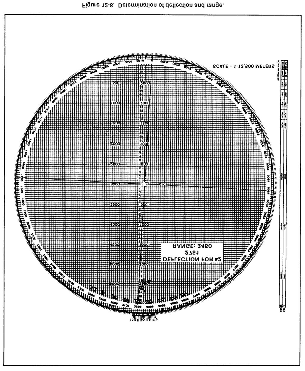
5 (e) Another method that can be used is to turn to page II in the FT. There is a listing of charges for M374A2 (HE) and M375A2 (WP) from charge 0 through charge 9. Below that listing is the charge listing for M301A3 illumination (illum) from charge 0 through charge 8. Write in after each charge the minimum and the maximum ranges that each charge zone covers (Figure 12-6). By looking at the maximum range, the correct charge to use can easily be determined. (6) Plotting of observer corrections. To plot the FO s corrections, the computer first indexes the FO s direction to the target. That OT direction is given in the call-for-fire or with the first correction. Going from the last round, he applies the FO s corrections. (a) For example, assume that the OT direction is 3050, and the FO sends these corrections: RIGHT 50, DROP 200. Ensuring that OT direction is indexed, make these corrections from the first plot (Figure 12-7, page 12-6). (b) To do this, move to the right one small square (50 meters), or the equivalent of one small square, then straight down the board four small squares (200 meters), or the equivalent of four small squares. Then, make a small plot, circle it, and label it "No. 2." To determine the firing data, rotate the disk until the No. 2 plot is over the vertical centerline. Then, read the deflection and range (Figure 12-8, page 12-7). Using the FT, determine the charge and elevation to fire the round, and compute the subsequent fire command. (c) Once the end of mission (EOM) has been given, update the M16/M19 plotting board (Figure 12-9, page 12-8). To do this, erase all the plots except the final plot. Then enclose that plot with a hollow cross and number it with the target number (Figure 12-10, page 12-8). (7) Engagement of other targets. To fire other targets on this chart, the computer must perform the following actions: (a) Grid. Go back to the map, plot the target location, and determine the range and direction. (b) Shift. Index the FO s direction to the target and apply the correction from the known point, which must be plotted on the chart. 12-5
6 b. Below Pivot-Point Method. The observed firing chart (with mortars plotted below pivot point) is used when the ranges to the targets being engaged are over 3,200 meters. (When theinitial range to the target is 2,900 meters or more, mortars are always plotted below the pivot point.) (1) Two items are needed to setup the board for operation: a gun-target azimuth and a range from the mortar position to the target. To construct the chart (a) Index the gun-target azimuth. (b) Drop below the pivot point 1,000 meters for 60-mm mortars, 2,000 meters for the 81-mm mortars, and 3,000 meters for the 4.2-inch and 120-mm mortars. 12-6
7 12-7
8 12-8
9 (c) Plot the mortar position 500 meters left or right of the vertical centerline (Figure 12-11). (2) Once these actions have been taken, ensure that the azimuth disk is still indexed on the gun target azimuth. Then, from the mortar position, plot the first round at the 12-9
10 range determined using the parallel-line method of plotting (Figure 12-12). Determine the mounting azimuth and referred deflection the same way as with the pivot-point method. (3) To determine the firing data to send to the mortar, align the mortar position below the target being engaged using the parallel-line method of plotting. Then read the deflection using the azimuth disk and vernier scale and measure the range between the mortars and target. To align the mortar position and target, since the mortar position is being plotted away from the pivot point, use the parallel-line method of plotting. With 12-10
11 the mortar position and target plotted, rotate the disk until the mortar position and the target are an equal distance from, or on, the same vertical line (Figure 12-13). NOTE: All directions are read from bottom to top. (4) Now determine ranges differently than with the mortar position plotted at the pivot point. Count each of the 50-meter squares from the mortar position to the target or place the edge of the computer s record alongside the two plots on the plotting board (mortar and target). Then make a tick mark on the edge of the computer s record at 12-11

12 each plot. Using the alternate range scale to the left of the pivot point, lay the computer s record along this scale with the mortar tick mark at 0 and read the range (Figure 12-14)
13 (5) To update the board after the EOM is given or to engage other targets, use the same method as with the pivot-point method. NOTE: When operating the M16 plotting board as an observed firing chart (pivot-point or below-pivot-point methods), no correction factors are applied to the data. c. Mortars Plotted at Pivot Point. With the pivot pin inserted in the pivot point of the plotting board, the computer can use the range scale arm the same as with the range arm to determine deflections and range to both the initial and subsequent rounds. (1) Determine the range and direction to the center of the sector from a map or by visual observation. Round off the azimuth to the initial round or direction of fire (DOF) to the nearest 50 mils to determine a mounting azimuth, and superimpose a deflection scale on the azimuth disk. (2) Make the initial plot by indexing the DOF (or initial azimuth) to the initial round at the index mark. This may be different from the mounting azimuth because of the round-off rule. Use the scale on the vertical centerline to make the initial plot at the correct range. (3) When the FO calls in a target direction (the OT azimuth), index the azimuth disk on the M16/M19 plotting board at the OT azimuth. It remains indexed on that azimuth until the mission is completed. Plot corrections from the FO IAW procedures. Once a correction has been plotted, rotate the range arm until the right edge of the range arm is over the new plot. Determine the range to the nearest 25 meters, and read the deflection to the nearest mil using the vernier scale. (4) Plot additional corrections, and use the range scale arm to determine range and deflection. Once the azimuth disk is indexed on the OT azimuth, the disk does not have to be rotated to determine ranges or deflections. d. Mortars Plotted Below Pivot Point. With the pivot pin inserted in the pivot point, the computer can use the left edge of the range scale arm to plot the initial round. The mounting azimuth and azimuth to the initial round are determined as for mortars plotted at pivot point. The computer indexes the azimuth disk on the DOF and aligns the right edge of the range scale arm on the vertical centerline. Next j he makes a small plot at the zero range on the left edge of the range scale arm. Then, still using the left edge, he makes a small plot at the range for the initial round. The mortar position plot must be marked with a hollow cross to further identify its position. Once the initial round is fired, the range scale arm is removed, and the left edge is used as a range scale. e. Care and Cleaning of Plotting Boards. Plotting boards must be handled with care to prevent bending, scratching, or chipping. They must be kept away from excessive heat or prolonged exposure to the sun, which may cause them to warp. When storing a board, it is placed in its carrying case, base down, on a horizontal surface. It is not placed on edge or have other equipment stored on it. The plotting board can normally be cleaned with a nongritty (art gum) eraser. If the board is excessively dirty, a damp cloth is used. The contact surface of the disk and base are cleaned often. The disk is removed by pushing a blunt instrument through the pivot point hole from the back of the base
14 12-2. MODIFIED-OBSERVED FIRING CHART The modified-observed firing chart can be constructed on the M16 plotting board. It is constructed when the mortar position or target is known to survey accuracy. Three basic items needed to construct the modified observed chart are: a DOF (usually to the center of the platoon area of responsibility), one point (mortar position, target, or reference point) that must be known to surveyed accuracy (eight-digit grid coordinates), and a grid intersection to represent the pivot point. a. Determination of Direction of Fire. The section sergeant usually determines DOF. In most cases, it is to the center of sector. The mortar location can be surveyed by map inspection, terrain inspection, or pacing from a known point on an azimuth, as long as the position of the base gun is known to a valid eight digits, (1) For the 60-mm and 81-mm mortars, the grid intersection representing the pivot point (Figure 12-15) is between 1,500 and 2,000 meters forward of the mortar location. This allows the full range of the mortar to be used. NOTE: When using the M16 plotting board with the 4.2-inch and 120-mm mortars, the grid intersection selected should be 2,000 to 2,500 meters forward of the mortar position. (2) The grid intersection should be outside the area of responsibility. This ensures that the pivot point does not interfere with plotting targets or corrections. The grid 12-14

15 intersection is also as close as possible to the area of responsibility. This ensures that as much of the area of responsibility as possible will be on the plotting board. b. Superimposition of Grid System on Plotting Board. Once the grid intersection has been determined, the computer indexes 0 on the azimuth disk. He then drops down 2,000 meters below the pivot point and writes in the north/south indicator on the vertical centerline at the 2,000-meter mark. Next, he goes 2,000 meters to the left of the pivot point on the heavy center horizontal line and writes the east/west indicator. To complete the grid system, the computer writes in the other north/south, east/west grid numbers as though looking at a map. By numbering every other heavy dark line (two large squares) on the plotting board, he retains a scale of 1:12,500 on the board (Figure 12-16)
 Read like a map: RIGHT and UP. (3) Remember that the scale is 1:12,500 (each small square is 50 meters by 50 meters) (Figure 12-17).")
16 c. Plotting of Mortar Position. Now that a grid system is on the board, the computer can plot any grid coordinates. To do this, he must (1) Ensure that the azimuth disk is indexed at 0. (2) Read like a map: RIGHT and UP. (3) Remember that the scale is 1:12,500 (each small square is 50 meters by 50 meters) (Figure 12-17). To superimpose the deflection scale, the computer writes the referred deflection on the board the same way as with the observed chart. Firing data are determined by using the parallel-line method of plotting

 Index the DOF. (2) Drop below the pivot point on the vertical centerline 2,000 to 2,500 meters.")
17 d. Field-Expedient Method for Construction. If the grid coordinates of the mortar position are known but a map is not available for determining the grid intersection to represent the pivot point, the computer can construct the modified-observed firing chart by using the following procedures: (1) Index the DOF. (2) Drop below the pivot point on the vertical centerline 2,000 to 2,500 meters. (3) Go 500 to l,000 meters left or right of the vertical centerline and make a plot (Figure 12-18)
18 (4) Rotate the azimuth disk and index "0." (5) Determine the l,000-meter grid that contaim the mortars (Figure l2-l9). The first, second, fifth, and sixth numbers of the mortar grid give the 1,000-meter grid square. (6) Superimpose the grid system. (7) Replot the mortar location to the surveyed grid

 and two targets have been fired on (Figure 12-20).")
19 12-3. TRANSFER OF TARGETS Transfer is the process of transferring a target from the observed chart to the modified-observed chart, or from the modified-observed chart to the surveyed chart, as more information becomes available. This occurs since the targets transferred are known points to the FO and FDC, and these points may be used in future missions. Transfer is always done using chart data (deflection and range to the final plot). EXAMPLE Assume that the mortar section is at grid (six digits: observed chart) and two targets have been fired on (Figure 12-20). The platoon leader determines that the eight-digit grid to the mortar position is (modified-observed chart) and designates the grid intersection to represent the pivot point. The computer constructs the chart and transfers the targets from the observed chart (Figure 12-21, page 12-20)
20 NOTE: No firing corrections are used with the observed chart. Once transferred to the modified-observed chart, the altitude of the target is assumed to be the same as that of the mortar position. a. Target Plotting. After transfer, through coordination with the FO, an RP or target may be identified to valid eight-digit coordinates. The plotting board is then reconstructed as a surveyed chart. When the situation permits, a registration mission should be conducted on the point for which the valid eight-digit coordinates were determined. Then firing corrections are computed
21 (1) When transferring targets from one type of chart to another, remember that the target plots on the observed chart are plotted at the data it takes to hit the target. This is not always the locations of the targets. (2) The same holds true for the modified-observed chart, except that with some targets, altitude correction (VI) may have been used. When replotting the target at the end of the mission, strip this altitude correction from the command range and plot the target using this range. Using this procedure gives a more accurate picture of the exact location of the target than the observed chart; however, it is not always the actual location of the target. b. Plotting of Previously Fired Targets. At the completion of the surveyed registration mission and the computation of the firing corrections, previously fired targets plotted on the plotting board must be forward plotted. Since the surveyed chart is the most accurate chart to use, all information on it should be the most accurate possible. EXAMPLE When targets AL0010 and AL0011 (Table 12-1) were fired before the surveyed registration, the data and the plots included all firing corrections, even though they may have been unknown at the time of firing. To forward plot these targets, the computer strips the firing correction from the range and deflection to plot them at their actual location. NOTE: To strip out the corrections, the signs must be reversed DEFLECTION CONVERSION TABLE When an adjustment is made to a sheaf, such as after the completion of the registration, the sheaf is paralleled or converged if engaging a point-type target, or opened when engaging a wider target. In these situations, the computer must determine the new data and convert the deviation corrections required into mils. He can use the deflection conversion table (Figure 12-22, page 12-22) or the mil-relation formula


22 a. To use the DCT, first round off the range at which the section is firing to the nearest 100 meters. This is required because the ranges on the table are divided into 100-meter increments. Next, go down the range column to find the range. The deflection is in meters across the top of the card. b. Using the number of meters the FO requested to move the strike of the round, find that number of meters and go straight down that column until itintersects with the range. That number is the number of mils that would have to be applied to the mortar sight to move the strike of the round the required meters. If the range is greater than 4,000 meters, divide the range and mil correction by two
23 EXAMPLE The mortar section has completed a registration mission and is prepared to adjust the sheaf. The final adjusted range for the RP is 2,750 meters. The No. 1 and No. 3 mortars fire one round each. The FO sends the following corrections: NUMBER 3, R30; NUMBER 1, L20; END OF MISSION, SHEAF ADJUSTED. Any corrections of 50 meters or more must be refired. For this example, the last deflection fired from No. 1 and No. 3 was 2931 mils. Using the DCT, round off the range to the nearest 100 meters (2,800). Find 2,800 meters in the range column and, using the FO s corrections, find 30 and 20 in the deflection-in-meters column. Go across and down those columns to where they intersect. The table shows that the requirements are 11 mils for 30 meters and 7 mils for 20 meters. Using this information, use the previous deflection fired, which was 2931 mils. Since the FO s correction for the No. 3 mortar was R30, which equals R11 mils (using the LARS rule), subtract 11 mils from 2931 mils. This gives a new deflection of 2920 mils. The correction for No. 1 mortar was L20, which equals L7 mils. Using the LARS rule for deflection, add 7 mils to 2931, which gives a new deflection of 2938 mils. If there is no deflection conversion table available, use the mil-relation formula (W/R x M) to convert the corrections from meters to mils. To use the formula for the same FO s corrections of R30 and L20 used in the example cited, cover the item needed (in this case M [mils]). The remainder of the formula states: divide W (width in meters) by R (range in thousandths). W/R = 20/2.8 = M W/R = 30/2.8 = M These are exactly the same figures determined by using the DCT GRID MISSION For an observed chart, the grid coordinates of the target must be plotted on the map, and a direction and distance determined from the mortar location to the target. For modified and surveyed charts, index 0 and plot the target using the grid coordinates. NOTE: Corrections for VI can be used on the modified and surveyed charts SHIFT MISSION For an observed chart, the known point must be plotted on the firing chart. This may be a fired-in target or a mark-center-of-sector round. The OT azimuth is indexed, and 12-23
24 the correction applied is sent in the call for fire. For modified and surveyed charts, the same procedure is used as for the observed chart POLAR MISSION The FO s location must be plotted on the plotting board before a polar mission can be fired. For an observed chart, the location can be plotted in three ways: by resection, by direction and distance, or by range and azimuth from a known point. a. Resection (Figure 12-23). Plot two known points on the plotting board. Then index the azimuths the FO sends from these two points, and draw lines from the known points toward the bottom of the board. The intersection of these lines is the FO s location

25 b. Direction and Distance (Figure 12-24). The FO sends the computer the grid to the FO position. The computer then plots the grid on the map, determines the direction and distance from the mortar position to that grid, transfers the direction and distance to the plotting board, and plots the FO s location. c. Range and azimuth from a known point. The FO must send the range from the known point and the azimuth on which that point is seen. Once that is known, the computer can index the azimuth, drop below the known point the range given, and plot the FO s location (Figure 12-25, page 12-26). For modified and surveyed charts, the 12-25
26 FO s location can be plotted if the grid of the FO is known, by indexing "0" and plotting the FO grid. If the grid is not known, then the computer can use resection, direction and distance, or range and azimuth from a known point
Referred Deflection. NOTE: Use 2800 and 0700 to avoid any sight blocks caused by the cannon. Figure Preparation of the plotting board.
 Chapter 12 Referred Deflection 12-5. The aiming circle operator gives the referred deflection to the FDC after the section is laid. The referred deflection can be any 100-mil deflection from 0 to 6300,
FIELD-EXPEDIENT SURVEY TECHNIQUES
 APPENDIX C FIELD-EXPEDIENT SURVEY TECHNIQUES Surveyed locations may be provided by the artillery survey personnel. Normally, a map spot location to six-digit or eight-digit grid coordinates is estimated
FM CHAPTER 6 DIRECTION
 CHAPTER 6 DIRECTION Being in the right place at the prescribed time is necessary to successfully accomplish military missions. Direction plays an important role in a soldier's everyday life. It can be
6-1. METHODS OF EXPRESSING DIRECTION
 CHAPTER 6 DIRECTION Being in the right place at the prescribed time is necessary to successfully accomplish military missions. Direction plays an important role in a soldier's everyday life. It can be
LESSON 6: DETERMINING DIRECTION
 LESSON 6: DETERMINING DIRECTION PURPOSE Directions play an important role in everyday life. People oftentimes express them as right, left, straight ahead, and so forth; but then the question arises, to
Lesson 7 Determining Direction. Key Terms. azimuth back azimuth degree grid azimuth grid north magnetic azimuth magnetic north true north
 Lesson 7 Determining Direction U.S. ARMY Key Terms J R O T C azimuth back azimuth degree grid azimuth grid north magnetic azimuth magnetic north true north WHAT YOU WILL LEARN TO DO Calculate direction
Reconnaissance and Surveillance Leader s Course Map Reading self study worksheet (Tenino, Washington Map)
") Reconnaissance and Surveillance Leader s Course Map Reading self study worksheet (Tenino, Washington Map) General Knowledge 1. Name the five Basic Colors on a map and what they represent? 1. 2. 3. 4. 5.
Reconnaissance and Surveillance Leader s Course Map Reading self study worksheet (Tenino, Washington Map) General Knowledge 1. Name the five Basic Colors on a map and what they represent? 1. 2. 3. 4. 5.
LOCATION W140005XQ STUDENT HANDOUT
 UNITED STATES MARINE CORPS THE BASIC SCHOOL MARINE CORPS TRAINING COMMAND CAMP BARRETT, VIRGINIA 22134-5019 LOCATION W140005XQ STUDENT HANDOUT W14005XQ Introduction Importance In This Lesson The class
Rutherford Atomic Model: Hidden Obstacles Student Advanced Version
 Rutherford Atomic Model: Hidden Obstacles Student Advanced Version This lab demonstrates the techniques that scientists used over a century ago to determine the basic structure of the atom. By rolling
Section 4.1 Investigating Circles
 Section 4.1 Investigating Circles A circle is formed when all the points in a plane that are the same distance away from a center point. The distance from the center of the circle to any point on the edge
CE 260 SURVEYING CHAPTER 5 THEODOLITES
 CE 260 SURVEYING CHAPTER 5 THEODOLITES General Background: Theodolites or Transits are surveying instruments designed to precisely measure horizontal and vertical angles. 1 They are used to establish straight
Math Lesson Plan 6th Grade Curriculum Total Activities: 302
 TimeLearning Online Learning for Homeschool and Enrichment www.timelearning.com Languages Arts, Math and more Multimedia s, Interactive Exercises, Printable Worksheets and Assessments Student Paced Learning
Grade 4 ISTEP+ T1 #1-2 ISTEP+ T1 # Identify, describe and draw parallelograms, rhombuses, and ISTEP+ T1 #5-6
 Unit 1 Naming and Constructing Geometric Figures 1 a B Use a compass and straightedge to construct geometric figures. 4.4.1 Identify, describe, and draw rays, right angles, acute angles, obtuse ISTEP+
Be sure to label all answers and leave answers in exact simplified form.
 Pythagorean Theorem word problems Solve each of the following. Please draw a picture and use the Pythagorean Theorem to solve. Be sure to label all answers and leave answers in exact simplified form. 1.
Right Triangles CHAPTER. 3.3 Drafting Equipment Properties of 45º 45º 90º Triangles p. 189
 CHAPTER Right Triangles Hiking is the most popular outdoor activity in the United States, with almost 40% of Americans hiking every year. Hikers should track their location and movements on a map so they
California Standard Study Island Topic Common Core Standard
 State: CA Subject: Math Grade Level: 4 California Standard Study Island Topic Standard NUMBER SENSE 1.0: Students understand the place value of whole numbers and decimals to two decimal places and how
Semester 2 Review Problems will be sectioned by chapters. The chapters will be in the order by which we covered them.
 Semester 2 Review Problems will be sectioned by chapters. The chapters will be in the order by which we covered them. Chapter 9 and 10: Right Triangles and Trigonometric Ratios 1. The hypotenuse of a right
Mathematics. Name: Class: Transforming Life chances
 Mathematics Name: Class: Transforming Life chances Children first- Aspire- Challenge- Achieve Aspire: To be the best I can be in everything that I try to do. To use the adults and resources available both
Unit 1, Lesson 1: Moving in the Plane
 Unit 1, Lesson 1: Moving in the Plane Let s describe ways figures can move in the plane. 1.1: Which One Doesn t Belong: Diagrams Which one doesn t belong? 1.2: Triangle Square Dance m.openup.org/1/8-1-1-2
MATH 1112 Trigonometry Final Exam Review
 MATH 1112 Trigonometry Final Exam Review 1. Convert 105 to exact radian measure. 2. Convert 2 to radian measure to the nearest hundredth of a radian. 3. Find the length of the arc that subtends an central
Angles and Directions
 Angles and Directions Angles and Directions Definitions Systems of Angle Measurement Angle Arithmetic Horizontal and Vertical Angles Angle and Direction Measuring Equipment 1 Angle Definitions A measure
Illinois State Standards Alignments Grades Three through Six
 Illinois State Standards Alignments Grades Three through Six Trademark of Renaissance Learning, Inc., and its subsidiaries, registered, common law, or pending registration in the United States and other
Chapter 1. Linear Equations and Straight Lines. 2 of 71. Copyright 2014, 2010, 2007 Pearson Education, Inc.
 Chapter 1 Linear Equations and Straight Lines 2 of 71 Outline 1.1 Coordinate Systems and Graphs 1.4 The Slope of a Straight Line 1.3 The Intersection Point of a Pair of Lines 1.2 Linear Inequalities 1.5
ENGINEERING SURVEYING (221 BE)
") ENGINEERING SURVEYING (221 BE) Horizontal Circular Curves Sr Tan Liat Choon Email: tanliatchoon@gmail.com Mobile: 016-4975551 INTRODUCTION The centre line of road consists of series of straight lines interconnected
ENGINEERING SURVEYING (221 BE) Horizontal Circular Curves Sr Tan Liat Choon Email: tanliatchoon@gmail.com Mobile: 016-4975551 INTRODUCTION The centre line of road consists of series of straight lines interconnected
RightStart Mathematics
 Most recent update: March 27, 2019 RightStart Mathematics Corrections and Updates for Level G/Grade 6 Lessons and Worksheets, second edition LESSON / WORKSHEET / SOLUTIONS CHANGE DATE CORRECTION OR UPDATE
Reflowing Xbox 360 Motherboard
 Reflowing Xbox 360 Motherboard Reflow the solder on your Xbox 360's motherboard. Written By: Andrew Bookholt ifixit CC BY-NC-SA www.ifixit.com Page 1 of 31 INTRODUCTION Use this guide to reflow the solder
Stage 6 Checklists Have you reached this Standard?
 Stage 6 Checklists Have you reached this Standard? Main Criteria for the whole year. Multiply and divide numbers with up to three decimal places by 10, 100, and 1000 Use long division to divide numbers
3RD GRADE COMMON CORE VOCABULARY M-Z
 o o o 3RD GRADE COMMON CORE VOCABULARY M-Z mass mass mass The amount of matter in an object. Usually measured by comparing with an object of known mass. While gravity influences weight, it does not affect
Gateway Regional School District VERTICAL ALIGNMENT OF MATHEMATICS STANDARDS Grades 3-6
 NUMBER SENSE & OPERATIONS 3.N.1 Exhibit an understanding of the values of the digits in the base ten number system by reading, modeling, writing, comparing, and ordering whole numbers through 9,999. Our
UNIT 4 INTRODUCTION TO FRACTIONS AND DECIMALS
 UNIT 4 INTRODUCTION TO FRACTIONS AND DECIMALS INTRODUCTION In this Unit, we will investigate fractions and decimals. We have seen fractions before in the context of division. For example, we can think
You ll use the six trigonometric functions of an angle to do this. In some cases, you will be able to use properties of the = 46
 Math 1330 Section 6.2 Section 7.1: Right-Triangle Applications In this section, we ll solve right triangles. In some problems you will be asked to find one or two specific pieces of information, but often
FRST 557. Lecture 9c. Switchbacks Vertical and Horizontal Design. Lesson Background and Overview:
 FST 557 Lecture 9c Switchbacks Vertical and Horizontal Design J u s t g iv e it o n e try, a n d if it don t w o rk w e ll c a ll in th e road crew to fix er up Lesson Background and Overview: Switchbacks
Level 3 will generally
 Same as Level4 understanding of the standard multiplication algorithm by analyzing partial products or errors use models and strategies to represent and solve realworld division without use of the standard
Year Long Mathematics Plan Fourth Grade First Quarter: Discovering Patterns and Relationships (~5 weeks)
") Year Long Mathematics Plan Fourth Grade First Quarter: Discovering Patterns and Relationships (~5 weeks) *Concepts covered: patterns, relationships, T-tables, and graphs. *Critical Content: comparing,
Year Long Mathematics Plan Fourth Grade First Quarter: Discovering Patterns and Relationships (~5 weeks) *Concepts covered: patterns, relationships, T-tables, and graphs. *Critical Content: comparing,
You ll use the six trigonometric functions of an angle to do this. In some cases, you will be able to use properties of the = 46
 Math 1330 Section 6.2 Section 7.1: Right-Triangle Applications In this section, we ll solve right triangles. In some problems you will be asked to find one or two specific pieces of information, but often
MS WORD INSERTING PICTURES AND SHAPES
 MS WORD INSERTING PICTURES AND SHAPES MICROSOFT WORD INSERTING PICTURES AND SHAPES Contents WORKING WITH ILLUSTRATIONS... 1 USING THE CLIP ART TASK PANE... 2 INSERTING A PICTURE FROM FILE... 4 FORMATTING
Distance in mm from nearest latitude line to location x 150 = seconds of latitude Distance in mm between latitude 2.5 tick marks (along the sides)
") LATITUDE FORMULA FOR 1:24000 SCALE WITH 2.5 TICK MARKS Distance in mm from nearest latitude line to location x 150 = seconds of latitude Distance in mm between latitude 2.5 tick marks (along the sides)
LATITUDE FORMULA FOR 1:24000 SCALE WITH 2.5 TICK MARKS Distance in mm from nearest latitude line to location x 150 = seconds of latitude Distance in mm between latitude 2.5 tick marks (along the sides)
Laboratory 6: Light and the Laser
 Laboratory 6: Light and the Laser WARNING NEVER LOOK DIRECTLY AT LASER LIGHT Index of Refraction: Snell's Law 1. Read the section on physical optics in some introductory physics text. 2. Set the semicircular
College Algebra Exam File - Fall Test #1
 College Algebra Exam File - Fall 010 Test #1 1.) For each of the following graphs, indicate (/) whether it is the graph of a function and if so, whether it the graph of one-to one function. Circle your
Cecil Jones Academy Mathematics Fundamentals
 Fundamentals Year 7 Knowledge Unit 1 Unit 2 Understand and use decimals with up to three decimal places Work with numbers up to ten million Explore the use of negative numbers Develop understanding of
Number and Operation Standard #1. Divide multi- digit numbers; solve real- world and mathematical problems using arithmetic.
 Number and Operation Standard #1 MN Math Standards Vertical Alignment for Grade 5 Demonstrate mastery of multiplication and division basic facts; multiply multi- digit numbers; solve real- world and mathematical
REMOTE PAGER SYSTEM RACEAIR TM QUICK START GUIDE
 RACEAIR TM REMOTE PAGER SYSTEM Introduction: Computech s RaceAir Remote Competition Weather Station with the Data Pager System consists of; the RaceAir Remote Sensor Assembly, the Computer Interface, the
Distance in mm from nearest latitude line to location x 150 = seconds of latitude Distance in mm between latitude 2.5 tick marks (along the sides)
") LATITUDE FORMULA FOR 1:24000 SCALE WITH 2.5 TICK MARKS Distance in mm from nearest latitude line to location x 150 = seconds of latitude Distance in mm between latitude 2.5 tick marks (along the sides)
LATITUDE FORMULA FOR 1:24000 SCALE WITH 2.5 TICK MARKS Distance in mm from nearest latitude line to location x 150 = seconds of latitude Distance in mm between latitude 2.5 tick marks (along the sides)
TEST EXAM PART 2 INTERMEDIATE LAND NAVIGATION
 NAME DATE TEST EXAM PART 2 INTERMEDIATE LAND NAVIGATION 1. Knowing these four basic skills, it is impossible to be totally lost; what are they? a. Track Present Location / Determine Distance / Sense of
Georgia Performance Standards for Fourth Grade
 Georgia Performance Standards for Fourth Grade Mathematics Terms for Georgia s (CRCT) Criterion Reference Competency Test Administered in April of Each Year Parents: We are counting on you to help us teach
1. Be sure to complete the exploration before working on the rest of this worksheet.
 PreCalculus Worksheet 4.1 1. Be sure to complete the exploration before working on the rest of this worksheet.. The following angles are given to you in radian measure. Without converting to degrees, draw
Field Handbook Supervision
 Field Handbook Supervision Contents CE Declaration of Conformity 2 Laser Cautions 2 LaserHead Use and Safety 3 Attaching the LaserHead to Profiler 4 Assembly 5 Attaching Profiler 6 Operation of SnapOn
MATHEMATICS Grade 4 Standard: Number, Number Sense and Operations. Organizing Topic Benchmark Indicator Number and Number Systems
 Standard: Number, Number Sense and Operations A. Use place value structure of the base-ten number system to read, write, represent and compare whole numbers and decimals. 2. Use place value structure of
2nd GRADE-Math Year at a Glance
 2nd Grade - Math Year at a Glance: 2017-2018 Chariton Community School District Operations and Algebraic Thinking Represent and solve problems Number and Operations in Base Ten Use place value understanding
Oracle <Insert Picture Here>
 Slide 1 Oracle Slide 2 WZT-6509 version B Sun Fire Nehalem and Westmere Rack-Mount Server Installation and Replacement Welcome to the installation and replacement
President of X DOT, Inc. NSMA 2014 Conference
 Coordinate Inaccuracies Presented by James C. Wolfson President of X DOT, Inc. NSMA 2014 Conference Introduction Review FCC/FAA coordinate and elevation requirements FAA Accuracy Codes Examples Tower site,
Grades 3-5 Special Education Math Maps First Grading Period
 First Grading Period 3-4 M E. Tell time to the nearest minute. 3-4 PFA B. Use patterns to make predictions, identify relationships, and solve problems. 3-4 NSO F. Count money and make change using both
Math Vocabulary Grades PK - 5
 Math Vocabulary ades P - 5 P 1 2 3 4 5 < Symbol used to compare two numbers with the lesser number given first > Symbol used to compare two numbers with the greater number given first a. m. The time between
Visual Physics Camera Parallax Lab 1
 In this experiment you will be learning how to locate the camera properly in order to identify and minimize the sources of error that are introduced by parallax and perspective. These sources of error
MA 154 Lesson 1 Delworth
 DEFINITIONS: An angle is defined as the set of points determined by two rays, or half-lines, l 1 and l having the same end point O. An angle can also be considered as two finite line segments with a common
Document Editor Basics
 Document Editor Basics When you use the Document Editor option, either from ZP Toolbox or from the Output option drop-down box, you will be taken to the Report Designer Screen. While in this window, you
The Smith Chart. One-to-one mapping between and z L z. More generally, anywhere along the transmission line. The math looks simple.
 The Smith Chart One-to-one mapping between and z L z z L L 1 1 z L 1 1 More generally, anywhere along the transmission line The math looks simple. But and z L are generally both complex. Actual calculation
First Trimester Second Trimester Third Trimester
 STANDARD 1 Number Sense: Develop number sense and use numbers and number relationships in problem-solving situations and communicate the reasoning used in solving these problems. (Aligned to Everyday Mathematics
Everyday Math and the Indiana Academic Standards for Grade 4 Mathematics
 Unit One 1.2-1.3 Identify, describe, and draw rays, right angles, acute angles, 4.4.1 Geometry Right Time Geometry obtuse angles and straight angles using appropriate mathematical tools and technology.
The Microscope: A Tool of the Scientist
 Name Class Date Microscope Lab The Microscope: A Tool of the Scientist Background Information (You may refer to page 61 of your textbook.) Problem One of the most important tools of a life scientist is
Archdiocese of Washington Catholic Schools Academic Standards Mathematics
 5 th GRADE Archdiocese of Washington Catholic Schools Standard 1 - Number Sense Students compute with whole numbers*, decimals, and fractions and understand the relationship among decimals, fractions,
Objective: Find areas by decomposing into rectangles or completing composite figures to form rectangles.
 Lesson 13 3 4 Lesson 13 Objective: Find areas by decomposing into rectangles or completing composite Suggested Lesson Structure Fluency Practice Application Problem Concept Development Student Debrief
SHAPE, SPACE & MEASURE
 STAGE 1 Know the place value headings up to millions Recall primes to 19 Know the first 12 square numbers Know the Roman numerals I, V, X, L, C, D, M Know the % symbol Know percentage and decimal equivalents
Objective: Use attributes to draw different polygons including triangles, quadrilaterals, pentagons, and hexagons. (7 minutes) (5 minutes)
 (5 minutes)") Lesson 3 2 8 Lesson 3 Objective: Suggested Lesson Structure Fluency Practice Application Problem Concept Development Student Debrief Total Time (12 minutes) (6 minutes) (32 minutes) (10 minutes) (60 minutes)
Lesson 3 2 8 Lesson 3 Objective: Suggested Lesson Structure Fluency Practice Application Problem Concept Development Student Debrief Total Time (12 minutes) (6 minutes) (32 minutes) (10 minutes) (60 minutes)
Objective: Construct a coordinate system on a plane.
 Lesson 2 Objective: Construct a coordinate system on a plane. Suggested Lesson Structure Fluency Practice Application Problem Concept Development Student Debrief Total Time (10 minutes) (7 minutes) (33
Microscopic Measurement
 Microscopic Measurement Estimating Specimen Size : The area of the slide that you see when you look through a microscope is called the " field of view ". If you know the diameter of your field of view,
ALGEBRA 1 NOTES. Quarter 3. Name: Block
 2016-2017 ALGEBRA 1 NOTES Quarter 3 Name: Block Table of Contents Unit 8 Exponent Rules Exponent Rules for Multiplication page 4 Negative and Zero Exponents page 8 Exponent Rules Involving Quotients page
2nd Grade Math Standards Learning Targets
 Standards Learning Target(s) Social Studies Skills MGSE2.NBT.1 Understand I can understand that the three digits of a three-digit Understand that the three digits of a number represent amounts of hundreds.
11.3 Surface Area of Pyramids and Cones
 11.3 Surface Area of Pyramids and Cones Learning Objectives Find the surface area of a pyramid. Find the surface area of a cone. Review Queue 1. A rectangular prism has sides of 5 cm, 6 cm, and 7 cm. What
Mathematics LV 4 (with QuickTables)
") Mathematics LV 4 (with QuickTables) This course covers the topics shown below. Students navigate learning paths based on their level of readiness. Institutional users may customize the scope and sequence
Mathematics LV 4 (with QuickTables) This course covers the topics shown below. Students navigate learning paths based on their level of readiness. Institutional users may customize the scope and sequence
Name: Teacher: Form: LEARNER JOURNAL. Set: Mathematics. Module 2 END OF YEAR TARGET: GCSE TARGET:
 Name: Teacher: Form: Set: LEARNER JOURNAL Mathematics Module 2 END OF YEAR TARGET: GCSE TARGET: MODULE 2 use a number line to represent negative numbers use inequalities with negative numbers compare and
Lesson 4: Angular measure and azimuths
 PRO TIPS: Map Reading Lesson 4: Angular measure and azimuths References: FM 21-25; FM 21-26; Map Lesson 4 in map section. Study assignment: read FM 21-25 Chapters 7 to 9, then go through this lesson and
UNIT 6 OPERATIONS WITH DECIMALS
 UNIT 6 OPERATIONS WITH DECIMALS INTRODUCTION In this Unit, we will use our understanding of operations, decimals, and place value to perform operations with decimals. The table below shows the learning
Area. Domain 4 Lesson 25. Getting the Idea
 Domain 4 Lesson 5 Area Common Core Standard: 7.G.6 Getting the Idea The area of a figure is the number of square units inside the figure. Below are some formulas that can be used to find the areas of common
K-6 Mathematics. Grade Level Vocabulary
 Grade Level Vocabulary K-6 In Edmonds School District, we believe students need to be taught how to read and speak the language of mathematics. While mathematical language can be confusing for students,
Oklahoma Learning Pathways
 BUI L F OKL ORT AHO MA 2015 2016 Oklahoma Learning Pathways Table of Contents Grade 3...3 Grade 4...5 Grade 5...8 Grade 6... 11 Grade 7... 15 Grade 8... 19 Algebra Readiness...22 Algebra I...25 Geometry...28
Binoculars. with. Digital Compass. Instruction Manual. Model: Lit. #: /08-12
 Binoculars with Digital Compass Model: 137570 Instruction Manual Lit. #: 98-1192/08-12 Right Eyepiece Focus Compass Power Switch Battery Cover Left Eyepiece Focus Parts Reference Tripod Attachment Socket
EF85mm f/1.2l II USM
 EF85mm f/1.2l II USM ENG Instruction Thank you for purchasing a Canon product. The Canon EF85mm f/1.2l II USM lens is a high-performance medium telephoto lens developed for EOS cameras. It is equipped
Instructors Manual. for. Construction Surveying and Layout. Third Edition. Part Two - Officework and Calculations. Chapters
 Instructors Manual for Construction Surveying and Layout Third Edition Part Two - Officework and Calculations Chapters 11-18 Prepared by Wesley G. Crawford TABLE OF CONTENTS Chapter 11 - Officework Practices...
Summer Solutions Common Core Mathematics 6. Common Core. Mathematics. Help Pages
 6 Common Core Mathematics 6 Vocabulary absolute deviation absolute value a measure of variability; in a set of data, the absolute difference between a data point and another point, such as the mean or
Place Value to Thousands
 Place Value to Thousands You can show,0 in a place-value chart. The value of each digit in a number depends on its place in the number. In,0 the value of: is hundred thousand or 00,000. is ten thousands
Excerpt from "Inside CorelCAD" - Windows edition To purchase the full book, please go to
 chapter 3 CAD Concepts 37 1. Start any drawing command, such as Line. : line Specify start point» (Move cursor.) 2. Right-click the coordinate field. Notice the short cut menu. 3. Choose Relative. (The
An Introduction to GeoGebra
 An Introduction to GeoGebra Downloading and Installing Acquiring GeoGebra GeoGebra is an application for exploring and demonstrating Geometry and Algebra. It is an open source application and is freely
QRPGuys Single Lever Keyer/Paddle
 QRPGuys Single Lever Keyer/Paddle First, familiarize yourself with the parts and check for all the components. If a part is missing, please contact us and we will send one. You must use qrpguys.parts@gmail.com
Area. Angle where two rays. Acute angle. Addend. a number to be added. an angle measuring less than 90 degrees. or line segments share an endpoint
 Acute angle Addend an angle measuring less than 90 degrees a number to be added Angle where two rays or line segments share an endpoint Area the measure of space inside a figure. Area is measured in square
Precalculus 4.1 Notes Angle Measures, Arc Length, and Sector Area
 Precalculus 4.1 Notes Angle Measures, Arc Length, and Sector Area An angle can be formed by rotating one ray away from a fixed ray indicated by an arrow. The fixed ray is the initial side and the rotated
ED-1100 PORTABLE VARIABLE EDDY CURRENT INSTRUMENT
 ED-1100 PORTABLE VARIABLE EDDY CURRENT INSTRUMENT EQUIPMENT SPECIFICATION ES-110-1 - 1.0 Description 1.1 The Model ED-1100 is a microprocessor based variable frequency eddy current instrument, with a liquid
Keysight M8000 Series BER Test Solutions
 Keysight M8000 Series BER Test Solutions J-BERT M8020A High-Performance BERT M8030A Multi-Channel BERT M8040A High-Performance BERT M8041A, M8051A, M8061A, M8062A, M8045A, M8046A & M8057A Tips for Preventing
PointWrite Touch Module User Manual
 PointWrite Touch Module User Manual Version: 1 Keep this user manual for future references. Table of contents Shipping Contents... 3 Product Overview... 4 About Touch Module...4 Dimensions...4 Preparation
Henrico County Public Schools Elementary Mathematics. SOL Math Vocabulary. Henrico County Public Schools Elementary Mathematics
 Henrico County Public Schools K-5 Attached is the K-5 SOL content specific mathematics vocabulary taken from the VDOE Curriculum Framework. This vocabulary is the mathematical language that should be used
Panasonic VRF Software. New features of VRF software
 Panasonic VRF Software New features of VRF software April 2013 1 Contents: Mounting scheme... 5 1. Import building scheme into software... 5 1.1. Export building scheme as DXF from AutoCAD... 5 1.2. Export
2. A circle is inscribed in a square of diagonal length 12 inches. What is the area of the circle?
 March 24, 2011 1. When a square is cut into two congruent rectangles, each has a perimeter of P feet. When the square is cut into three congruent rectangles, each has a perimeter of P 6 feet. Determine
Loading Transfer Ribbon
 14 Loading Transfer Ribbon Loading Transfer Ribbon The GT-Series printer has a flexible ribbon system. It supports 300 meter and 74 meter genuine Zebra ribbons. It also supports third party ribbons with
HIGH ORDER QUESTION STEMS STUDENT SCALE QUESTIONS FCAT ITEM SPECIFICATION
 Benchmark Support Task Cards MA.3.A.1.1 BENCHMARK: MA.3.A.1.1 Model multiplication and division, including problems presented in context: repeated addition, multiplicative comparison, array, how many combinations,
SHOW ME THE NUMBERS: DESIGNING YOUR OWN DATA VISUALIZATIONS PEPFAR Applied Learning Summit September 2017 A. Chafetz
 SHOW ME THE NUMBERS: DESIGNING YOUR OWN DATA VISUALIZATIONS PEPFAR Applied Learning Summit September 2017 A. Chafetz Overview In order to prepare for the upcoming POART, you need to look into testing as
Groveport Madison Local School District Third Grade Math Content Standards. Planning Sheets
 Standard: Patterns, Functions and Algebra A. Analyze and extend patterns, and describe the rule in words. 1. Extend multiplicative and growing patterns, and describe the pattern or rule in words. 2. Analyze
EzyRings. Table of Contents
 vcomp Pty Ltd (ABN 39 103 040 311) PO Box 7356 Cloisters Square Perth WA 6850 Telephone +618 9312 6158 Fax +618 9312 6158 EzyRings Reporting System Table of Contents Report Designer... 3 Company Header...
EXCEL SKILLS. Selecting Cells: Step 1: Click and drag to select the cells you want.
 Selecting Cells: Step 1: Click and drag to select the cells you want. Naming Cells: Viewlet available Step 2: To select different cells that are not next to each other, hold down as you click and
13 Vectorizing. Overview
 13 Vectorizing Vectorizing tools are used to create vector data from scanned drawings or images. Combined with the display speed of Image Manager, these tools provide an efficient environment for data
Route Surveying. Topic Outline
 Route Surveying CE 305 Intro To Geomatics By Darrell R. Dean, Jr., P.S., Ph.D. Topic Outline Horizontal alignment Types of Horizontal Curves Degree of Curve Geometric elements of curve Station ti number