CATIA V5 Parametric Surface Modeling
|
|
|
- Mildred Barnett
- 5 years ago
- Views:
Transcription

1 CATIA V5 Parametric Surface Modeling Version 5 Release 16 A- 1

2 Toolbars in A B A. Wireframe: Create 3D curves / lines/ points/ plane B. Surfaces: Create surfaces C. Operations: Join surfaces, Split & Trim surfaces, Change the 3D positions of surfaces, Fillets D. Replication: Pattern, Powercopy E. Analysis: Connection analysis, Draft analysis, curvature analysis F. Surface-based Features: (On Part Design Workbench), create a solid from surfaces, modify the solid by a surface A- 2 F D C E
 Point A- 3")
3 Point (Create a point in the 3D space) Point A- 3
, which is")

4 Extremum (max or min point) Extremum (create an extremum element (point, edge, or face), which is at the minimum or maximum distance on a curve, a surface, or a pad, according to given directions. ) A- 4

")
5 Line (Create a line in the 3D space) Line A- 5

 A-")
6 Plane Plane (Create a plane in the 3D space) A- 6 A-6


7 Projection onto a support Projection (project one or more elements onto a support. The projection can be normal to surface or along a specified direction.) Normal to surface Along a direction (vertical) A- 7


8 Combine Curves Combine Curves (create a curve resulting from the intersection of the extrusion of two curves. ) A 3D resultant Curve A- 8

9 Reflect Line Reflect Line (create curves for which the normal to the surface in each point present the same angle with a specified direction. They can be closed or open.) The normal of surface at all points along the curve is 38deg from the vertical axis A- 9

 Intersection curve between two")

10 Intersection Intersection (create wireframe geometry by intersecting elements.) Intersection curve between two surfaces Intersection point between a curve and a surface Intersection curve between a surface and a solid A- 10

 Offset the curve on the surface")
 We have a curve lying")
11 Parallel Curve Parallel Curve (create a curve that is parallel to a reference curve.) Offset the curve on the surface (The resultant curve is still on the surface) We have a curve lying on the surface A- 11


12 Corner Corner (create a corner between two curves) If several solutions may be possible, click the Next Solution button to move to another corner solution, or directly select the corner you want in the geometry A- 12
 Point-continuous, tangent-continuous or curvature-continuous Point-continuous, tangent-continuous or curvature-continuous The")
13 Connect Curve Connect Curve (create a connecting curve between two curves. ) Point-continuous, tangent-continuous or curvature-continuous Point-continuous, tangent-continuous or curvature-continuous The curvature in the middle can be controlled by tension A- 13

14 Spline Curve Spline Curve (create a 2D/ 3D spline curve) We can create an additional line to define the tangent direction at a point. A- 14
 First Create a point")
 Follows")
15 Helix Helix (create a helix curve like a spring) First Create a point and a straight line (Optional) With Taper Angle A- 15 (Optional) Follows a profile

16 Extrude Extrude (create a surface by extruding a profile along a given direction) If the profile is planar, the direction will be its normal by default. But you can change it to other direction. A- 16
 Remark: The axis must be a straight line. Sketch.1 Line.")
17 Revolve Revolve (create a surface by revolving a planar profile about an axis) Remark: The axis must be a straight line. Sketch.1 Line.1 A- 17
 A-")
18 Offset Offset (create a surface, or a set of surfaces, by offsetting an existing surface, or a set of surfaces) A- 18
 - With two guide curves (optional) - With pulling direction")


19 Sweep Sweep (create a surface by sweeping out a profile along one or two guide curves) Sweeping an Explicit profile - With reference surface (optional) - With two guide curves (optional) - With pulling direction (optional) (We can use the above three options to control the profile orientation) Sweeping a Linear profile - Two limits - Limit and middle - With reference surface - With tangency surface - With reference curve - With two tangency surfaces - With draft direction Profile We first create a guide curve (4 lines) A- 19 Guide Curve Explicit Line Circular Conical Then create a draft surface by sweeping an inclined linear profile along a guide curve


20 Sweep Con t Sweeping a Circular profile - Three guides - Two guides and radius - Center and two angles - Center and radius - Two guides and tangency surface - One guide and tangency surface Sweeping a Conical profile - Two guides - Three guides - Four guides - Five guides A- 20

 Passing through a point (optional) Support Surface Support Surface")
21 Fill Fill (create a surface to fill the opening among a number of boundary segments) The four points must be tangent-continuous or curvature-continuous We can specify the desired continuity type between any selected support surfaces and the fill surface (Point, Tangent or Curvature continuous) Passing through a point (optional) Support Surface Support Surface A- 21


22 Multi-sections Surface Multi-sections surface (create a surface by sweeping two or more section curves along an automatically computed or user-defined spine. The surface can be made to respect one or more guide curves. ) Further control pointpoint matching by manual coupling A- 22
")
23 Blend (Create a surface between two wireframe elements or surface edges) Blend A- 23
 A- 24")

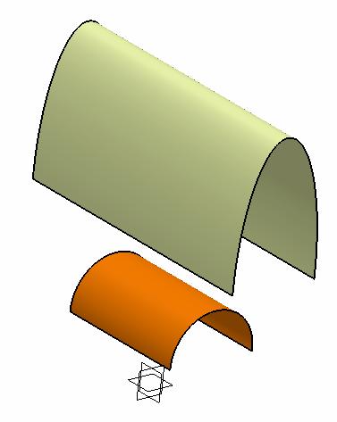
24 Join Join (join surfaces or curves as one element) A- 24 The two original surfaces are hidden; a Join surface is created

 Split Trim Cutting Element Original Result by Split Element to Cut Trim (trim two or more")
25 Split & Trim Split (split a surface or wireframe element by means of a cutting element. You can split a wireframe element by a point, another wireframe element or a surface; or a surface by a wireframe element or another surface. ) Split Trim Cutting Element Original Result by Split Element to Cut Trim (trim two or more surface or wireframe elements) Result by Trim A- 25

 A- 26")

26 Boundary Boundary (create the boundary curve of a surface) A- 26 We can select limit points to limit the boundary

27 Extract Extract (extract from elements (curves, points, surfaces or solids) Only Selected surface Only tangent surfaces are selected All surfaces are selected A- 27 For this case, the extracted element must be a curve.
 Smooth: a tangency constraint is imposed at the connection")

28 Shape Fillet Bi-tangent Shape Fillet (create a shape fillet between two surfaces) Smooth: a tangency constraint is imposed at the connection between the fillet surface and the support surfaces, thus smoothing the connection. Tri-tangent Shape Fillet (create a shape fillet between three surfaces) A- 28


29 Edge Fillet Edge Fillet (create a constant radius fillet along the internal edge of a joined surface) Select the edge of the Join Surface A- 29

 Click the box and select the point Create a point along the edge before filleting A- 30 After")
30 Variable Fillet Variable Fillet (create a variable radius fillet. In this type of fillet, the radius varies at selected points along a selected edge. The fillet surface is obtained by rolling a sphere, which radius would vary, over the selected edge. ) Click the box and select the point Create a point along the edge before filleting A- 30 After entering a new value for this point, we have a different radius here


31 Face-Face Fillet Face-Face fillet (create a face-face fillet. The fillet surface is obtained by rolling a sphere, which radius is larger than the distance between the selected elements, between the selected surfaces. ) Remark: This is a Joined Surface We can add this fillet between two faces that are not touching each other A- 31


32 Tri-tangent Fillet Tri-tangent Fillet (The creation of tritangent fillets involves the removal of one of the three faces selected, as the fillet surface is obtained by rolling a sphere, which radius is automatically computed to be larger than the removed surface, between the selected surfaces.) A- 32


33 Translate, Rotate, Symmetry, Scale Translate Rotate Translate Rotate Symmetry Scale Affinity Symmetry Scale A- 33 Affinity


34 Extrapolate a surface boundary: Extrapolate Tangent Continuity this will be a straight edge Tangent/Curvature Extrapolate a Curve: We can join the extrapolated surface with the original surface Extrapolation without support A- 34 Extrapolation with a support


35 Patterns Rectangular pattern Rectangular pattern Circular pattern User pattern First create a sketch with points Circular pattern User pattern A- 35
 / (( C1 + C2")
 / (( C1 + C2 ) / 2) A-")
36 Connect Checker Connect Checker (analyze how two surfaces are connected ) Distance - minimal distance between two vertices Tangency - angle between two surfaces Curvature Difference ( C2 - C1 ) / (( C1 + C2 ) / 2) Curve Connect Checker (analyze how two curves are connected ) Distance - minimal distance between two vertices Tangency - angle between two curves Curvature Difference ( C2 - C1 ) / (( C1 + C2 ) / 2) A- 36
 1 2 STEPS: 1. Click Feature Draft Analysis 2. Define the color scale (e.g. -1, 0, +1 deg) 3. Click the option Compass on the pop-up menu 4.")
37 Draft Analysis (analyze the draft angle on a surface) Draft Analysis (Remark: To view the draft result, we need to use the Shading with Material mode.) 1 2 STEPS: 1. Click Feature Draft Analysis 2. Define the color scale (e.g. -1, 0, +1 deg) 3. Click the option Compass on the pop-up menu 4. Select all surfaces 4 3 A- 37

 To MOVE a surface from One")

38 Create a New Geometrical Set To CREATE a new geometrical set:- - Select Insert/Geometrical Set on the top menu - Click ok (Remark: Provided that Hybrid Design is disabled, a geometrical set will be created automatically when the first wireframe/ surface/ plane is created) To MOVE a surface from One Geometrical Set to the other:- -Right-click on the surface to access the contextual menu -Select Change Geometrical Set -Select the other geometrical set from the list of Destination A- 38


39 Remark: Split (by Surface) The surface-based features (Split, Thick Surface, Close surface & Sew) are available only on Part Design Workbench Split (split a solid with a plane, face or surface ) A- 39


40 Thick Surface Thick Surface (add material to a surface in two opposite directions or in one direction) A- 40
 A-")
41 Close Surface Close Surface (Add material inside the enclosed surface so that a solid is created) A- 41


42 Sew Surface Sew Surface (a Boolean operation combining a surface with a body. This capability adds or removes material by modifying the surface of the solid.) A- 42

43 Exercise Exercise 1 - Sweep/ Extrude/ Offset - Blend/ Split/ Boundary - Fill/ Join Exercise 2 - Revolve/ Sweep/ Split - Shape Fillet/ Extrude - Symmetry/ Join - Thick Surface A- 43
 with symmetric endpoints as shown in Fig.2 Click Exit to complete A- 44 Fig.1 Fig.")
44 No sharp edges along the boundary Exercise 1 A A Section A-A (1) Start/Shape/ (2) To make a Sweep surface:- Click Sketch icon and select yz plane Draw an arc (R500) with one end (0,0) as shown in Fig.1 Click Exit to complete Deselect Sketch.1 Click Sketch icon again and select zx plane Draw an arc (R400) with symmetric endpoints as shown in Fig.2 Click Exit to complete A- 44 Fig.1 Fig.2

 (4) To make a sketch on the offset plane:- Click Sketch icon and select Plane.")
45 (Con t) Click Sweep icon Select Explicit as Profile Type Select Sketch.1 as Profile Select Sketch.2 as Guide Curve Hide Sketch.1 & Sketch.2 Exercise 1 (3) To make an Offset Plane:- Click Plane icon Select xy plane as Reference Enter 160mm as Offset (upward) (4) To make a sketch on the offset plane:- Click Sketch icon and select Plane.1 Draw the Profile as shown in Fig.3 Click Exit to complete A- 45 Fig.3


 To Offset the surface:- Click Offset icon Select Sweep.")
46 (5) To Project the sketch onto the surface:- Click Projection icon Select Along a direction as Projection type Select Sketch.3 as Projected Select Sweep.1 as Support Select xy plane as Direction Exercise 1 (6) To Split the surface:- Click Split icon Select Sweep.1 as Element to cut Select Project.1 as Cutting element (Click Other Side option to choose the outer portion) Hide Sketch.3 & Project.1 (6b) To Offset the surface:- Click Offset icon Select Sweep.1 as Surface Enter 6mm as Offset (Downward) A- 46
 Exercise 1 Plane.2 Plane.3 (8) To Split Surfaces:- Hide Surface Split.1; Show Surface Sweep.")

47 (7) To Create Two offset planes:- Click Plane icon Select zx plane as Reference Enter 50mm as Offset (positive side) Click Plane icon again Select zx plane as Reference Enter 230mm as Offset (positive side) Exercise 1 Plane.2 Plane.3 (8) To Split Surfaces:- Hide Surface Split.1; Show Surface Sweep.1 Click Split icon Select Sweep.1 as Element to cut Select Plane.2 as Cutting element Click Other Side option to choose the smaller portion Click Split icon again Select Offset.1 as Element to cut Select Plane.3 as Cutting element Click Other Side option to choose the smaller portion A- 47 Result of Split.2 Result of Split.3


48 (9) To Create a Blend:- Click Blend icon Select the edge of Split.2 as First Curve Select Split.2 as First Support Select the edge of Split.3 as Second Curve Select Split.3 as Second Support Select Tangency for First continuity and Second continuity Exercise 1 (10) To make a sketch on the offset plane:- Click Sketch icon and select Plane.1 Draw the Profile as shown in Fig.4 Click Exit to complete A- 48 Fig.4


49 (11) To Project the sketch onto the Blend:- Click Projection icon Select Along a direction as Projection type Select Sketch.4 as Projected Select Blend.1 as Support Select xy plane as Direction Exercise 1 (12) To Split the Blend:- Click Split icon Select Blend.1 as Element to cut Select Project.2 as Cutting element (Click Other Side option to choose the inner portion) Hide Sketch.4 & Project.2 A- 49
 To make 4 boundaries:- (1 st Boundary) Click Boundary icon Select Tangency continuity as Propagation type Select the edge as shown in Fig.")
50 (13) To Hide all constructive elements:- Hide all elements except Split.1 & Split.4 Exercise 1 Split.4 Split.1 (14) To make 4 boundaries:- (1 st Boundary) Click Boundary icon Select Tangency continuity as Propagation type Select the edge as shown in Fig.5 1 st Boundary 2 nd Boundary (2 nd Boundary) Click Boundary icon again Select Tangency continuity as Propagation type Select the edge as shown in Fig.5 Fig.5 A- 50
 Click Boundary icon again Select the edge as shown in Fig.")
 To Create a Fill:- Click Fill icon Select Boundary.1 then Split.4 then Tangent Select Boundary.")
51 (3 rd Boundary) Click Boundary icon again Select the edge as shown in Fig.6 Select the point as Limit 1 (4 th Boundary) Click Boundary icon again Select the edge as shown in Fig.6 Select the point as Limit 1 Exercise 1 4 th Boundary Fig.6 3 rd Boundary (15) To Create a Fill:- Click Fill icon Select Boundary.1 then Split.4 then Tangent Select Boundary.2 then Split.1 then Tangent Select Boundary.3 then Split.1 then Tangent Select Boundary.4 then Split.1 then Tangent A- 51 Split.4 Split.1


52 Exercise 1 (16) To Join surfaces:- Click Join icon Select Split.1, Fill.1 & Split.4 (17) Hide all Boundaries Result: No sharp edge between the step-down and the original surface A- 52 END of Exercise.1
 Click Exit to")
53 Exercise 2 (1) Start/Shape/ (2) To make a Revolve surface:- Click Sketch icon and select zx plane Draw an arc (R160) with one end (0,30) as shown in Fig.1, which should be tangent to a horizontal axis Draw another horizontal axis on x-axis (which will be selected to be the axis of rotation later) Click Exit to complete Fig.1 A- 53
 Enter 0deg as")
 To make the 2 nd Sketch:- Click Sketch icon and select xy")
54 (con t) Click Revolve icon Select Sketch.1 as Profile (Sketch axis will be selected as Revolution axis) Enter 0deg as Angle.1 Enter 180deg as Angle.2 Hide Sketch.1 Exercise 2 (3) To make the 2 nd Sketch:- Click Sketch icon and select xy Plane Draw an Arc (R90) as shown in Fig.2 Click Exit icon to complete Fig.2 A- 54
 Exercise 2 yz plane Click Plane icon again select yz Plane then select the end point of")

55 (4) To make reference planes:- Click Plane icon select yz Plane then select the end point of the arc ( Parallel through point will be automatically selected as Plane Type ) Exercise 2 yz plane Click Plane icon again select yz Plane then select the end point of the arc touching Sketch.2 (5) To make the 3 rd Sketch:- Click Sketch icon and select Plane.1 Draw an ellipse with one end touching Sketch.2 as shown in Fig.3 (While adding the constraint (D30), rightclick and select semiminor axis ) Click Exit to complete A- 55 Fig.3


 Click Exit to")
 To make a symmetric curve:- Click")
56 (6) To make the 4 th Sketch:- Click Sketch icon and select Plane.2 Draw an ellipse with one end touching Sketch.2 as shown in Fig.4 (While adding the constraint (D10), rightclick and select semiminor axis ) Click Exit to complete Exercise 2 Fig.4 touching Sketch.2 Result (7) To make a symmetric curve:- Click Symmetry icon Select Sketch.2 as Element select zx Plane as Reference Zx plane A- 56

 A-")
57 (7) To make a Multi-sections Surface:- Click Multi-sections Surface icon Select Sketch.3 as Section#1 Select Sketch.4 as Section#2 Select Sketch.2 as Guide#1 Select Symmetry.1 as Guide#2 Hide Sketch.2, Sketch.3, Sketch.4, Symmetry.1, Plane.1 & Plane.2 Exercise 2 (8) To Split the surface:- Click Split icon Select Multi-sections Surface.1 as Element to cut Select zx Plane as Cutting element (Click Other Side option to choose the correct portion) A- 57 Zx Plane

) as shown in Fig.")
58 (9) To make a Fillet between 2 surfaces:- Click Shape Fillet icon Select Split.1 as Support.1 Select Trim Support.1 Select Revolute.1 as Support.2 Select Trim Support.2 Enter 10mm as Radius (Click on the red arrow if it is not pointing outward) Exercise 2 (10) To make 5 th Sketch:- Click Sketch icon and select xy Plane Draw an Arc (R78, center at (0,0)) as shown in Fig.5 (One endpoint must be on x-axis) Circle center at (0,0) Endpoint on x-axis A- 58 Fig5

 To Split Surface:- Click Split icon Select")

59 (11) To make an Extrude:- Click Extrude icon Select Sketch.5 as Profile (The Sketch Plane, xy Plane will be automatically selected as Direction) Enter 20mm as Limit.1 Enter 20mm as Limit.2 Exercise 2 (12) To Split Surface:- Click Split icon Select Fillet.1 as Element to cut Select Extrude.1 as Cutting element (Click Other Side option to choose the bigger portion) Hide Extrude.1 & Sketch.5 A- 59
 To visual-check the tangency continuity along the interface:- Click Shading icon (All black surface edges now disappear) Check if any sharp")
60 (13) To make a Symmetry:- Click Symmetry icon Select Split.2 as Element Select zx Plane as Reference Exercise 2 (14) To visual-check the tangency continuity along the interface:- Click Shading icon (All black surface edges now disappear) Check if any sharp edge appears along the centre interface. If yes, go back to previous step(s) to correct the error. (15) To Join Surfaces:- Click Join icon Select Split.2 and Symmetry.2 as Elements to Join (Split.2 & Symmetry.2 will be hidden automatically) A- 60


 To add Fillets onto the solid:- Click Edge Fillet icon")
61 (16) To make a Solid:- Start/Mechanical Design/Part Design Click Thick Surface icon Click ok on the pop-up warning window Select Join.1 as Object to Offset Enter 2mm as First Offset (If the red-arrows are not pointing inward, click Reverse Direction or directly click on an arrow to change the direction) Hide Geometrical Set.1 Exercise 2 (17) To add Fillets onto the solid:- Click Edge Fillet icon Select all sharp edges Enter 0.5mm as Radius A- 61 END of Exercise.2
Additional Exercises. You will perform the following exercises to practice the concepts learnt in this course:
 Additional Exercises You will perform the following exercises to practice the concepts learnt in this course: Master Exercise : Mobile Phone Plastic Bottle Exercise 1 Master Exercise : Mobile Phone In
CATIA Surface Design
 CATIA V5 Training Exercises CATIA Surface Design Version 5 Release 19 September 2008 EDU_CAT_EN_GS1_FX_V5R19 Table of Contents (1/2) Creating Wireframe Geometry: Recap Exercises 4 Creating Wireframe Geometry:
Lesson 3: Surface Creation
 Lesson 3: Surface Creation In this lesson, you will learn how to create surfaces from wireframes. Lesson Contents: Case Study: Surface Creation Design Intent Stages in the Process Choice of Surface Sweeping
Solidworks 2006 Surface-modeling
 Solidworks 2006 Surface-modeling (Tutorial 2-Mouse) Surface-modeling Solid-modeling A- 1 Assembly Design Design with a Master Model Surface-modeling Tutorial 2A Import 2D outline drawing into Solidworks2006
Create Complex Surfaces
 Create Complex Surfaces In this lesson, you will be introduced to the functionalities available in the Generative Surface Design workbench. Lesson content: Case Study: Surface Design Design Intent Stages
Lesson 4: Surface Re-limitation and Connection
 Lesson 4: Surface Re-limitation and Connection In this lesson you will learn how to limit the surfaces and form connection between the surfaces. Lesson contents: Case Study: Surface Re-limitation and Connection
Generative Shape Design
 Generative Shape Design Copyright DASSAULT SYSTEMES 2002 1 Exercise 60 min. The Knob In this exercise you will have the opportunity to model an appliance Knob starting from an empty model. You will create
Education Curriculum Surface Design Specialist
 Education Curriculum Surface Design Specialist Invest your time in imagining next generation designs. Here s what we will teach you to give shape to your imagination. CATIA Surface Design Specialist CATIA
Inventor 201. Work Planes, Features & Constraints: Advanced part features and constraints
 Work Planes, Features & Constraints: 1. Select the Work Plane feature tool, move the cursor to the rim of the base so that inside and outside edges are highlighted and click once on the bottom rim of the
Mechanical Design V5R19 Update
 CATIA V5 Training Foils Mechanical Design V5R19 Update Version 5 Release 19 August 2008 EDU_CAT_EN_MD2_UF_V5R19 1 About this course Objectives of the course Upon completion of this course you will be able
A Comprehensive Introduction to SolidWorks 2011
 A Comprehensive Introduction to SolidWorks 2011 Godfrey Onwubolu, Ph.D. SDC PUBLICATIONS www.sdcpublications.com Schroff Development Corporation Chapter 2 Geometric Construction Tools Objectives: When
FreeStyle Shaper & Optimizer
 FreeStyle Shaper & Optimizer Preface What's New Getting Started Basic Tasks Advanced Tasks Workbench Description Customizing Glossary Index Dassault Systèmes 1994-99. All rights reserved. Preface CATIA
Licom Systems Ltd., Training Course Notes. 3D Surface Creation
 , Training Course Notes Work Volume and Work Planes...........................1 Overview..........................................1 Work Volume....................................1 Work Plane......................................1
Autodesk Inventor Design Exercise 2: F1 Team Challenge Car Developed by Tim Varner Synergis Technologies
 Autodesk Inventor Design Exercise 2: F1 Team Challenge Car Developed by Tim Varner Synergis Technologies Tim Varner - 2004 The Inventor User Interface Command Panel Lists the commands that are currently
Quick Surface Reconstruction
 CATIA V5 Training Exercises Quick Surface Reconstruction Version 5 Release 19 August 2008 EDU_CAT_EN_QSR_FX_V5R19 1 Table of Contents Master Exercise Presentation:Plastic Bottle 3 Design Intent - Plastic
FreeStyle Shaper Optimizer & Profiler
 FreeStyle Shaper Optimizer & Profiler Page 1 Preface Using This Guide More Information What's New? Getting Started Starting the FreeStyle Workbench Creating a First Surface Editing the Surface Creating
Parametric Modeling. With. Autodesk Inventor. Randy H. Shih. Oregon Institute of Technology SDC PUBLICATIONS
 Parametric Modeling With Autodesk Inventor R10 Randy H. Shih Oregon Institute of Technology SDC PUBLICATIONS Schroff Development Corporation www.schroff.com www.schroff-europe.com 2-1 Chapter 2 Parametric
Parametric Modeling with UGS NX 4
 Parametric Modeling with UGS NX 4 Randy H. Shih Oregon Institute of Technology SDC PUBLICATIONS Schroff Development Corporation www.schroff.com www.schroff-europe.com 2-1 Chapter 2 Parametric Modeling
Chapter 2 Parametric Modeling Fundamentals
 2-1 Chapter 2 Parametric Modeling Fundamentals Create Simple Extruded Solid Models Understand the Basic Parametric Modeling Procedure Create 2-D Sketches Understand the "Shape before Size" Approach Use
Structural & Thermal Analysis Using the ANSYS Workbench Release 12.1 Environment
 ANSYS Workbench Tutorial Structural & Thermal Analysis Using the ANSYS Workbench Release 12.1 Environment Kent L. Lawrence Mechanical and Aerospace Engineering University of Texas at Arlington SDC PUBLICATIONS
CATIA Electrical Space Reservation TABLE OF CONTENTS
 TABLE OF CONTENTS Introduction...1 Manual Format...2 Electrical Reservations...3 Equipment Reservations...5 Pathway Reservations...31 Advanced Reservations...49 Reservation Analysis...67 Clash...69 Sectioning...73
Lesson 6: Work in Multi-Model Environment with Surface
 Lesson 6: Work in Multi-Model Environment with Surface In this lesson, you will learn how to work in Multi-Model Environment with Surface. Lesson Contents: Case Study: Multi-Model Environment with Surface
Freestyle Shaper, Optimizer and Profiler
 CATIA V5 Training Foils Freestyle Shaper, Optimizer and Profiler Version 5 Release 19 August 2008 EDU_CAT_EN_FSS_FI_V5R19 1 About this course Objectives of the course In this course you will learn how
Modeling a Gear Standard Tools, Surface Tools Solid Tool View, Trackball, Show-Hide Snaps Window 1-1
 Modeling a Gear This tutorial describes how to create a toothed gear. It combines using wireframe, solid, and surface modeling together to create a part. The model was created in standard units. To begin,
Parametric Modeling with NX 12
 Parametric Modeling with NX 12 NEW Contains a new chapter on 3D printing Randy H. Shih SDC PUBLICATIONS Better Textbooks. Lower Prices. www.sdcpublications.com Powered by TCPDF (www.tcpdf.org) Visit the
Lesson 1 Parametric Modeling Fundamentals
 1-1 Lesson 1 Parametric Modeling Fundamentals Create Simple Parametric Models. Understand the Basic Parametric Modeling Process. Create and Profile Rough Sketches. Understand the "Shape before size" approach.
Module 4A: Creating the 3D Model of Right and Oblique Pyramids
 Inventor (5) Module 4A: 4A- 1 Module 4A: Creating the 3D Model of Right and Oblique Pyramids In Module 4A, we will learn how to create 3D solid models of right-axis and oblique-axis pyramid (regular or
Lesson 2: Wireframe Creation
 Lesson 2: Wireframe Creation In this lesson you will learn how to create wireframes. Lesson Contents: Case Study: Wireframe Creation Design Intent Stages in the Process Reference Geometry Creation 3D Curve
SOLIDWORKS 2016: A Power Guide for Beginners and Intermediate Users
 SOLIDWORKS 2016: A Power Guide for Beginners and Intermediate Users The premium provider of learning products and solutions www.cadartifex.com Table of Contents Dedication... 3 Preface... 15 Part 1. Introducing
Structural & Thermal Analysis using the ANSYS Workbench Release 11.0 Environment. Kent L. Lawrence
 ANSYS Workbench Tutorial Structural & Thermal Analysis using the ANSYS Workbench Release 11.0 Environment Kent L. Lawrence Mechanical and Aerospace Engineering University of Texas at Arlington SDC PUBLICATIONS
Autodesk Fusion 360: Model. Overview. Modeling techniques in Fusion 360
 Overview Modeling techniques in Fusion 360 Modeling in Fusion 360 is quite a different experience from how you would model in conventional history-based CAD software. Some users have expressed that it
Autodesk Inventor 6 Essentials Instructor Guide Chapter Four: Creating Placed Features Chapter Outline This chapter provides instruction on the follow
 Chapter Four: Creating Placed Features Chapter Outline This chapter provides instruction on the following topics and provides exercises for students to practice their skills. Day Two Topic: How to create
Design and Communication Graphics
 An approach to teaching and learning Design and Communication Graphics Solids in Contact Syllabus Learning Outcomes: Construct views of up to three solids having curved surfaces and/or plane surfaces in
3D ModelingChapter1: Chapter. Objectives
 Chapter 1 3D ModelingChapter1: The lessons covered in this chapter familiarize you with 3D modeling and how you view your designs as you create them. You also learn the coordinate system and how you can
Chapter 2 Parametric Modeling Fundamentals
 2-1 Chapter 2 Parametric Modeling Fundamentals Create Simple Extruded Solid Models Understand the Basic Parametric Modeling Procedure Create 2-D Sketches Understand the Shape before Size Approach Use the
Solid Bodies and Disjointed Bodies
 Solid Bodies and Disjointed Bodies Generally speaking when modelling in Solid Works each Part file will contain single solid object. As you are modelling, each feature is merged or joined to the previous
Module 4B: Creating Sheet Metal Parts Enclosing The 3D Space of Right and Oblique Pyramids With The Work Surface of Derived Parts
 Inventor (5) Module 4B: 4B- 1 Module 4B: Creating Sheet Metal Parts Enclosing The 3D Space of Right and Oblique Pyramids With The Work Surface of Derived Parts In Module 4B, we will learn how to create
3. Preprocessing of ABAQUS/CAE
 3.1 Create new model database 3. Preprocessing of ABAQUS/CAE A finite element analysis in ABAQUS/CAE starts from create new model database in the toolbar. Then save it with a name user defined. To build
Introduction to ANSYS DesignModeler
 Lecture 5 Modeling 14. 5 Release Introduction to ANSYS DesignModeler 2012 ANSYS, Inc. November 20, 2012 1 Release 14.5 Preprocessing Workflow Geometry Creation OR Geometry Import Geometry Operations Meshing
Parametric Modeling. with. Autodesk Inventor Randy H. Shih. Oregon Institute of Technology SDC
 Parametric Modeling with Autodesk Inventor 2009 Randy H. Shih Oregon Institute of Technology SDC PUBLICATIONS Schroff Development Corporation www.schroff.com Better Textbooks. Lower Prices. 2-1 Chapter
Skateboard. Hanger. in the Feature Manager and click Sketch on the Context toolbar, Fig. 1. Fig. 2
 Chapter 3 Skateboard Hanger A. Sketch1 Lines. Step 1. Click File Menu > New, click Part Metric and OK. Step 2. Click Right Plane in the Feature Manager and click Sketch on the Context toolbar, Fig. 1.
Nose Cone. Chapter 4. Rocket 3D Print. A. Revolve. Step 1. Click File Menu > New, click Part and OK. SOLIDWORKS 16 Nose Cone ROCKET 3D PRINT Page 4-1
 Chapter 4 Rocket 3D Print Nose Cone A. Revolve. Step 1. Click File Menu > New, click Part and OK. Step 2. Click Front Plane in the Feature Manager and click Sketch on the content toolbar, Fig. 1. Step
Battery Holder. Chapter 9. Boat. A. Front Extrude. Step 1. Click File Menu > New, click Part and OK. SolidWorks 10 BATTERY HOLDER AA BOAT Page 9-1
 Chapter 9 Boat Battery Holder A. Front Extrude. Step 1. Click File Menu > New, click Part and OK. AA Step 2. Click Front (plane) in the Feature Manager and click Sketch from the Content toolbar, Fig. 1.
Solid Modeling: Part 1
 Solid Modeling: Part 1 Basics of Revolving, Extruding, and Boolean Operations Revolving Exercise: Stepped Shaft Start AutoCAD and use the solid.dwt template file to create a new drawing. Create the top
Parametric Modeling with. Autodesk Fusion 360. First Edition. Randy H. Shih SDC. Better Textbooks. Lower Prices.
 Parametric Modeling with Autodesk Fusion 360 First Edition Randy H. Shih SDC PUBLICATIONS Better Textbooks. Lower Prices. www.sdcpublications.com Powered by TCPDF (www.tcpdf.org) Visit the following websites
COPYRIGHT DASSAULT SYSTEMES Version 5 Release 19 January 2009 EDU-CAT-EN-ASL-FS-V5R19
 CATIA Training CATIA Aerospace Sheet Metal Design Detailed Steps COPYRIGHT DASSAULT SYSTEMES Version 5 Release 19 January 2009 EDU-CAT-EN-ASL-FS-V5R19 Table of Contents Additional Exercise: Aerostructure...3
Create the Through Curves surface
 Create the Through Curves surface 1. Open ffm4_mc_fender. 2. Select all three strings, and then on the Analyze Shape toolbar, click Show End Points. Notice there are two curves in the strings on the left
3D Design with 123D Design
 3D Design with 123D Design Introduction: 3D Design involves thinking and creating in 3 dimensions. x, y and z axis Working with 123D Design 123D Design is a 3D design software package from Autodesk. A
An Introduction to Autodesk Inventor 2012 and AutoCAD Randy H. Shih SDC PUBLICATIONS. Schroff Development Corporation
 An Introduction to Autodesk Inventor 2012 and AutoCAD 2012 Randy H. Shih SDC PUBLICATIONS www.sdcpublications.com Schroff Development Corporation Visit the following websites to learn more about this book:
VERO UK TRAINING MATERIAL
 VERO UK TRAINING MATERIAL VISI Basic 2-D Modelling course (V-16) VISI Modelling 2D Design Introduction Many component designs follow a similar route, beginning with a 2D design, part modelled using solids
SOLIDWORKS: Lesson III Patterns & Mirrors. UCF Engineering
 SOLIDWORKS: Lesson III Patterns & Mirrors UCF Engineering Solidworks Review Last lesson we discussed several more features that can be added to models in order to increase their complexity. We are now
Exercise Guide. Published: August MecSoft Corpotation
 VisualCAD Exercise Guide Published: August 2018 MecSoft Corpotation Copyright 1998-2018 VisualCAD 2018 Exercise Guide by Mecsoft Corporation User Notes: Contents 2 Table of Contents About this Guide 4
An Introduction to Autodesk Inventor 2013 and AutoCAD
 An Introduction to Autodesk Inventor 2013 and AutoCAD 2013 Randy H. Shih SDC PUBLICATIONS Schroff Development Corporation Better Textbooks. Lower Prices. www.sdcpublications.com Visit the following websites
Ansoft HFSS Solids Menu
 Ansoft HFSS Use the commands on the Solids menu to: Draw simple 3D objects such as cylinders, boxes, cones, and spheres. Draw a spiral or helix. Sweep a 2D object to create a 3D object. 2D objects can
SOLIDWORKS 2018 Reference Guide
 SOLIDWORKS 2018 Reference Guide A comprehensive reference guide with over 250 standalone tutorials David C. Planchard, CSWP, SOLIDWORKS Accredited Educator SDC PUBLICATIONS Better Textbooks. Lower Prices.
Module 1: Basics of Solids Modeling with SolidWorks
 Module 1: Basics of Solids Modeling with SolidWorks Introduction SolidWorks is the state of the art in computer-aided design (CAD). SolidWorks represents an object in a virtual environment just as it exists
An Introduction to Autodesk Inventor 2010 and AutoCAD Randy H. Shih SDC PUBLICATIONS. Schroff Development Corporation
 An Introduction to Autodesk Inventor 2010 and AutoCAD 2010 Randy H. Shih SDC PUBLICATIONS Schroff Development Corporation www.schroff.com 2-1 Chapter 2 Parametric Modeling Fundamentals Create Simple Extruded
3 AXIS STANDARD CAD. BobCAD-CAM Version 28 Training Workbook 3 Axis Standard CAD
 3 AXIS STANDARD CAD This tutorial explains how to create the CAD model for the Mill 3 Axis Standard demonstration file. The design process includes using the Shape Library and other wireframe functions
Skateboard. Hanger. in the Feature Manager and click Sketch. (S) on the Sketch. Line
 on the Sketch. Line") Chapter 3 Skateboard Hanger A. Sketch 1. Step 1. Click File Menu > New, click Part Metric and OK. Step 2. Click Right Plane from the Content toolbar, Fig. 1. in the Feature Manager and click Sketch Step
Chapter 3 Skateboard Hanger A. Sketch 1. Step 1. Click File Menu > New, click Part Metric and OK. Step 2. Click Right Plane from the Content toolbar, Fig. 1. in the Feature Manager and click Sketch Step
Module 5: Creating Sheet Metal Transition Piece Between a Square Tube and a Rectangular Tube with Triangulation
 1 Module 5: Creating Sheet Metal Transition Piece Between a Square Tube and a Rectangular Tube with Triangulation In Module 5, we will learn how to create a 3D folded model of a sheet metal transition
User Guide. for. JewelCAD Professional Version 2.0
 User Guide Page 1 of 121 User Guide for JewelCAD Professional Version 2.0-1 - User Guide Page 2 of 121 Table of Content 1. Introduction... 7 1.1. Purpose of this document... 7 2. Launch JewelCAD Professional
Learning Autodesk Inventor 2014
 Learning Autodesk Inventor 2014 Modeling, Assembly and Analysis Randy H. Shih SDC P U B L I C AT I O N S Better Textbooks. Lower Prices. www.sdcpublications.com Visit the following websites to learn more
Surfacing using Creo Parametric 3.0
 Surfacing using Creo Parametric 3.0 Overview Course Code Course Length TRN-4506-T 3 Days In this course, you will learn how to use various techniques to create complex surfaces with tangent and curvature
Delta Dart. Socket. (L) on the Sketch toolbar. Fig. 1. (S) on the Sketch toolbar. on the Sketch toolbar. on the Standard Views toolbar.
 on the Sketch toolbar. Fig. 1. (S) on the Sketch toolbar. on the Sketch toolbar. on the Standard Views toolbar.") Chapter 6 Delta Dart Socket A. Sketch. Step 1. Click File Menu > New, click Part Metric and OK. Step 2. Click Front Plane in the Feature Manager and click Sketch from the Content toolbar, Fig. 1. Step
Chapter 6 Delta Dart Socket A. Sketch. Step 1. Click File Menu > New, click Part Metric and OK. Step 2. Click Front Plane in the Feature Manager and click Sketch from the Content toolbar, Fig. 1. Step
SheetMetal Design Version 5 Release 13. SheetMetal Design
 SheetMetal Design Page 1 Overview Conventions What's New? Getting Started Entering the Workbench Defining the Parameters Creating the First Wall Creating the Side Walls Creating a Cutout Creating Automatic
Equipment Support Structures
 Equipment Support Structures Overview Conventions What's New? Getting Started Setting Up Your Session Creating a Simple Structural Frame Creating Non-uniform Columns Creating Plates with Openings Bracing
Equipment Support Structures
 Page 1 Equipment Support Structures Preface Using This Guide Where to Find More Information Conventions What's New? Getting Started Setting Up Your Session Creating a Simple Structural Frame Creating Non-uniform
Feature-Based Modeling and Optional Advanced Modeling. ENGR 1182 SolidWorks 05
 Feature-Based Modeling and Optional Advanced Modeling ENGR 1182 SolidWorks 05 Today s Objectives Feature-Based Modeling (comprised of 2 sections as shown below) 1. Breaking it down into features Creating
The Beret-Palette Ring. Designed by Luiz Maia
 The Beret-Palette Ring Designed by Luiz Maia Table of Contents Part I Description of the model.p. 3 Part II Building the ring..p. 4-25 The beret-palette....p. 4-11 The shank/paintbrush p. 12 The handle
Course Modules for CATIA V6 2013x Essentials for New Users Training Online:
 Course Modules for CATIA V6 2013x - 100 Essentials for New Users Training Online: 1 Launching CATIA V6 The PLM Story Import IGI Models (Essentials) Launching CATIA V6 Choosing a Security Context 2 V6 Navigation
Autodesk Inventor 2018
 Learning Autodesk Inventor 2018 Modeling, Assembly and Analysis Randy H. Shih SDC PUBLICATIONS Better Textbooks. Lower Prices. www.sdcpublications.com Powered by TCPDF (www.tcpdf.org) Visit the following
Lesson 1: Creating T- Spline Forms. In Samples section of your Data Panel, browse to: Fusion 101 Training > 03 Sculpt > 03_Sculpting_Introduction.
 3.1: Sculpting Sculpting in Fusion 360 allows for the intuitive freeform creation of organic solid bodies and surfaces by leveraging the T- Splines technology. In the Sculpt Workspace, you can rapidly
Revolve Vertices. Axis of revolution. Angle of revolution. Edge sense. Vertex to be revolved. Figure 2-47: Revolve Vertices operation
 Revolve Vertices The Revolve Vertices operation (edge create revolve command) creates circular arc edges or helixes by revolving existing real and/or non-real vertices about a specified axis. The command
Delta Dart. Propeller. in the Feature Manager and click Sketch from the Content toolbar, Fig. 1. on the Sketch toolbar.
 Chapter 8 Delta Dart Propeller A. Base for Blade. Step 1. Click File Menu > New, click Part Metric and OK. Step 2. Click Top Plane in the Feature Manager and click Sketch from the Content toolbar, Fig.
Swept Blend Creates a quilt using swept blend geometry.
 Swept Blend Creates a quilt using swept blend geometry. 1 A surface can be defined by a set of cross-sections located at various points along a controlling Spine Curve. In Pro/SURFACE, this is known as
Complex Shapes Creation with Hybrid Modelling
 Complex Shapes Creation with Hybrid Modelling Peter De Strijker Technical Sales Executive MFG - Benelux Our Customer s Industries Discrete product manufacture Agenda Quality Analyses of sketches and surfaces
Siemens NX 6 Surface-modeling (Tutorial 2 Mouse)
") Siemens NX 6 Surface-modeling (Tutorial 2 Mouse) Surface-modeling Solid-modeling Assembly Design Design with a Master Model Design in Context Version 1a Feb 2010 Copyright 2010 by Intellectual Technology
Siemens NX 6 Surface-modeling (Tutorial 2 Mouse) Surface-modeling Solid-modeling Assembly Design Design with a Master Model Design in Context Version 1a Feb 2010 Copyright 2010 by Intellectual Technology
GDL Toolbox 2 Reference Manual
 Reference Manual Archi-data Ltd. Copyright 2002. New Features Reference Manual New Save GDL command Selected GDL Toolbox elements can be exported into simple GDL scripts. During the export process, the
TRAINING GUIDE SOLIDS-LESSON-3
 TRAINING GUIDE SOLIDS-LESSON-3 Mastercam Training Guide Objectives You will generate the solid model from the existing 2-dimensional geometry. This Lesson covers the following topics: Open an existing
Glider. Wing. Top face click Sketch. on the Standard Views. (S) on the Sketch toolbar.
 on the Sketch toolbar.") Chapter 5 Glider Wing 4 Panel Tip A. Open and Save As "WING 4 PANEL". Step 1. Open your WING BLANK file. Step 2. Click File Menu > Save As. Step 3. Key-in WING 4 PANEL for the filename and press ENTER.
Chapter 5 Glider Wing 4 Panel Tip A. Open and Save As "WING 4 PANEL". Step 1. Open your WING BLANK file. Step 2. Click File Menu > Save As. Step 3. Key-in WING 4 PANEL for the filename and press ENTER.
Lesson 2 Constructive Solid Geometry Concept. Parametric Modeling with I-DEAS 2-1
 Lesson 2 Constructive Solid Geometry Concept Parametric Modeling with I-DEAS 2-1 2-2 Parametric Modeling with I-DEAS Introduction In the 1980s, one of the main advancements in Solid Modeling was the development
Adding Fillet, Shell, and Draft Features
 Learn how to: Adding Fillet, Shell, and Draft Features I-DEAS Tutorials: Fundamental Skills add draft features add fillet features use the Ball Corner Fillet option add shell features Before you begin...
SolidWorks 2013 and Engineering Graphics
 SolidWorks 2013 and Engineering Graphics An Integrated Approach Randy H. Shih SDC PUBLICATIONS Schroff Development Corporation Better Textbooks. Lower Prices. www.sdcpublications.com Visit the following
Solid Bodies and Disjointed bodies
 Solid Bodies and Disjointed bodies Generally speaking when modelling in Solid Works each Part file will contain single solid object. As you are modelling, each feature is merged or joined to the previous
Multi-Axis Surface Machining
 CATIA V5 Training Foils Multi-Axis Surface Machining Version 5 Release 19 January 2009 EDU_CAT_EN_MMG_FI_V5R19 1 About this course Objectives of the course Upon completion of this course you will be able
SOLIDWORKS 2016 and Engineering Graphics
 SOLIDWORKS 2016 and Engineering Graphics An Integrated Approach Randy H. Shih SDC PUBLICATIONS Better Textbooks. Lower Prices. www.sdcpublications.com Powered by TCPDF (www.tcpdf.org) Visit the following
AutoCAD 2009 Tutorial
 AutoCAD 2009 Tutorial Second Level: 3D Modeling Randy H. Shih Oregon Institute of Technology SDC PUBLICATIONS Schroff Development Corporation www.schroff.com Better Textbooks. Lower Prices. AutoCAD 2009
Input CAD Solid Model Assemblies - Split into separate Part Files. DXF, IGES WMF, EMF STL, VDA, Rhino Parasolid, ACIS
 General NC File Output List NC Code Post Processor Selection Printer/Plotter Output Insert Existing Drawing File Input NC Code as Geometry or Tool Paths Input Raster Image Files Report Creator and Designer
Advanced CAD Modelling Course (SolidWorks 2009)
") Advanced CAD Modelling Course (SolidWorks 2009) Published by: The National Centre for Technology in Education And T4 Technology Subjects Support Service National Centre for Technology in Education Dublin
Advanced CAD Modelling Course (SolidWorks 2009) Published by: The National Centre for Technology in Education And T4 Technology Subjects Support Service National Centre for Technology in Education Dublin
Tools for Design. with VEX Robot Kit: Randy H. Shih Oregon Institute of Technology SDC PUBLICATIONS
 Tools for Design with VEX Robot Kit: AutoCAD 2011 and Autodesk Inventor 2011 2D Drawing 3D Modeling Hand Sketching Randy H. Shih Oregon Institute of Technology INSIDE: SUPPLEMENTAL FILES ON CD SDC PUBLICATIONS
Aerospace Sheet Metal Design
 CATIA V5 Training Foils Aerospace Sheet Metal Design Version 5 Release 19 January 2009 EDU_CAT_EN_ASL_FI_V5R19 1 About this course Objectives of the course Upon completion of this course you will be able
December 3, :30 to 5:30 pm. Speaker Name: Tom Short, P.E. Course Title: Taking A Step Into The World Of 3D
 Las Vegas, Nevada December 3, 2002 1:30 to 5:30 pm Speaker Name: Tom Short, P.E. Course Title: Taking A Step Into The World Of 3D Course ID: GD122 Course Outline: Are you an experienced AutoCAD 2D user
Alibre Design Tutorial - Simple Revolve Translucent Glass Lamp Globe
 Alibre Design Tutorial - Simple Revolve Translucent Glass Lamp Globe Part Tutorial Exercise 2: Globe-1 In this Exercise, We will set System Parameters first. Then, in sketch mode, we will first Outline
Autodesk Inventor 2016 Learn by doing. Tutorial Books
 Autodesk Inventor 2016 Learn by doing Tutorial Books Copyright 2015 Kishore This book may not be duplicated in any way without the express written consent of the publisher, except in the form of brief
Tools for Design. A practical guide to 2D Drawing, Sketching, 3D Parametric Modeling and Finite Element Analysis
 Tools for Design Using AutoCAD 2011, Autodesk Inventor 2011, and LEGO MINDSTORMS NXT & TETRIX A practical guide to 2D Drawing, Sketching, 3D Parametric Modeling and Finite Element Analysis INSIDE: SUPPLEMENTAL
Rhinoceros Car Modeling Tutorial
 Rhinoceros Car Modeling Tutorial This tutorial will guide you to car nurbs modeling process using Rhinoceros 3.0. To start a car modeling you will need some car images (or sketches) to get an idea of the
Aerospace Sheetmetal Design
 Aerospace Sheetmetal Design Page 1 Overview Conventions What's New? Getting Started Entering the Aerospace SheetMetal Design Workbench Defining the Aerospace SheetMetal Parameters Creating a Web from a
Doctor Walt s Solid Edge Version 19 Workbook 137
 Still using the SMART DIMENSION Tool, click on the left vertical edge of the sketch. Move the cursor to the left and click to set the text position. Type 1.5 for the value and hit the ENTER Key. Next,
Lecture 4, 5/27/2017, Rhino Interface an overview
 數字建築與城市设计 Spring 2017 Lecture 4, 5/27/2017, Rhino Interface an overview Copyright 2017, Chiu-Shui Chan. All Rights Reserved. This lecture concentrates on the use of tools, 3D solid modeling and editing
Autodesk Fusion 360 Training: The Future of Making Things Attendee Guide
 Autodesk Fusion 360 Training: The Future of Making Things Attendee Guide Abstract After completing this workshop, you will have a basic understanding of editing 3D models using Autodesk Fusion 360 TM to