Automated calculation report (example) Date 05/01/2018 Simulation type
|
|
|
- Hilda Roxanne Bruce
- 5 years ago
- Views:
Transcription

1 Automated calculation report (example) Project name Tesla Semi Date 05/01/2018 Simulation type Moving
2 Table of content Contents Table of content... 2 Introduction... 3 Project details... 3 Disclaimer D model... 4 Model details... 4 Views... 4 Drag... 6 Drag coefficient... 6 Drag force and power versus velocity... 6 Sources of drag underpressure... 7 Sources of drag overpressure... 9 Sources drag surface friction Wind flow patterns...13 Vertical set of streamlines...14 Horizontal set of streamlines D flow patterns - velocity D flow patterns - pressure Noise
3 Introduction Thank you for choosing AirShaper to analyze & optimize the aerodynamics of your design. We hope that this report will provide you with the necessary insight. Should you require further assistance, feel free to get in touch with our experts via Project details Project name Tesla semi Date 05/01/2018 Simulation type 3D file Moving tesla_semi.stl Rotation- X Y Z [ ] Units meters Wind speed [m/s] 25 Temperature [ C] 15 Density [kg/m³] Atmospheric pressure [Pa] Calculation algorithm V0.1 Number of cells Accuracy Speed Expert interpretation Normal Normal No Disclaimer Calculation results provided by AirShaper are based on a virtual wind tunnel. The size of this virtual wind tunnel is much larger than the flow phenomena you see on the images below. So don t worry, your model was not clamped between virtual walls. No matter how accurate, simulations are always a simplification or reality, containing modeling, discretization and iteration errors. Therefore, especially in safety critical applications, we always recommend to perform a physical wind tunnel test. To find a wind tunnel institute suited for your project, please contact us at info@airshaper.com 3

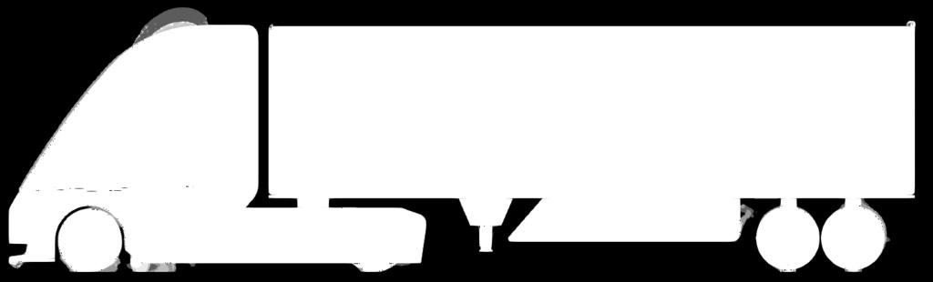
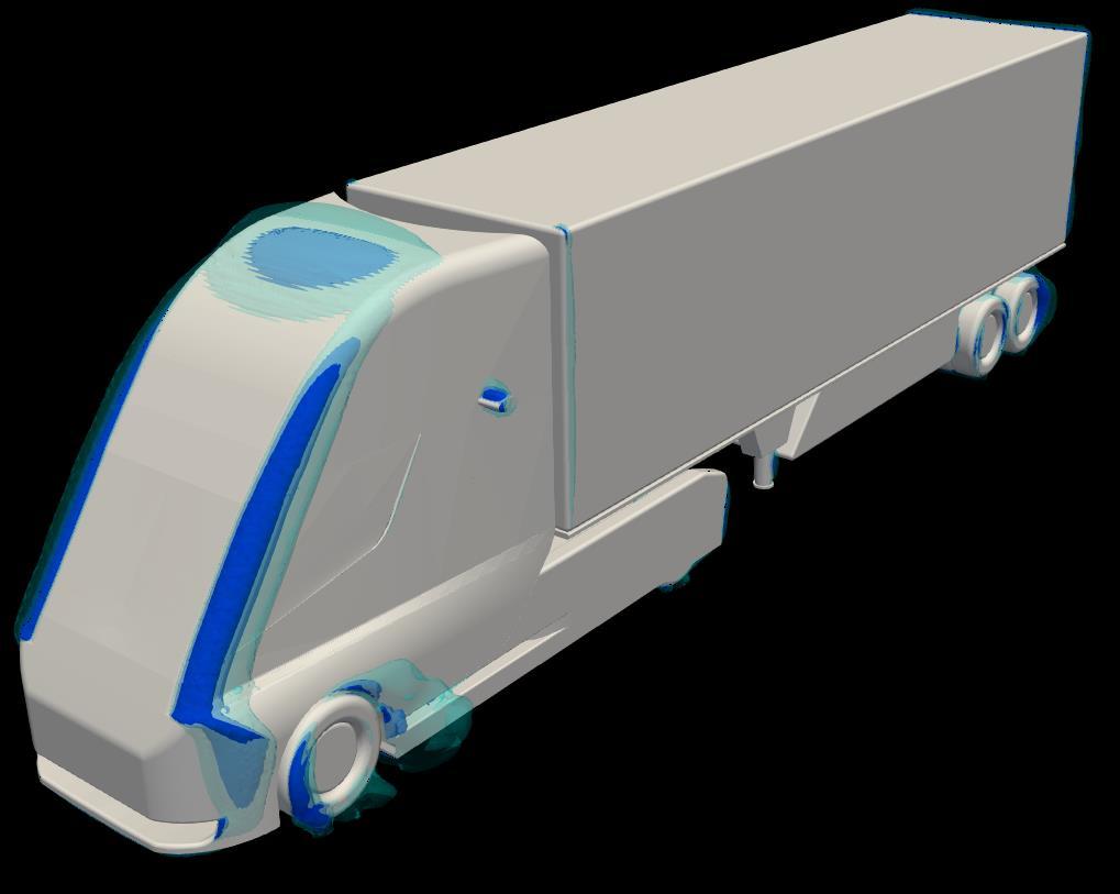
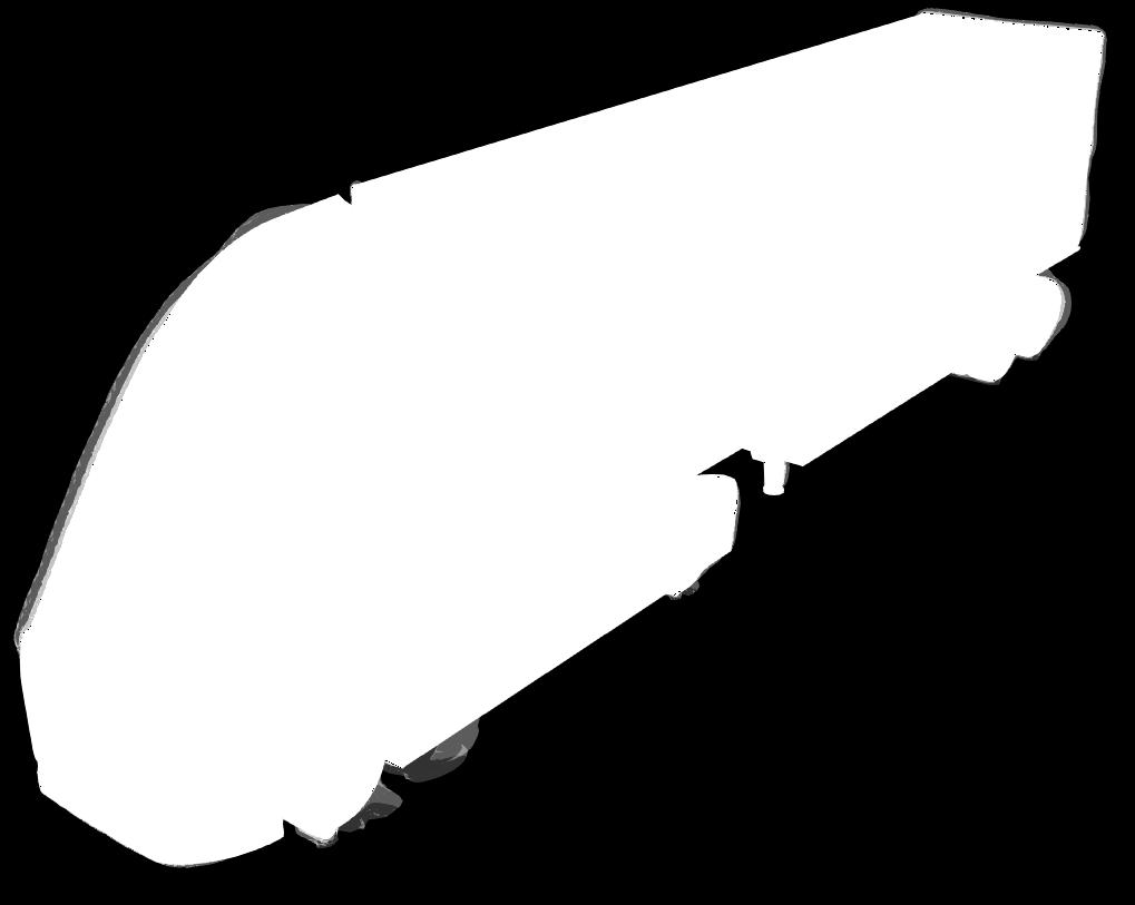
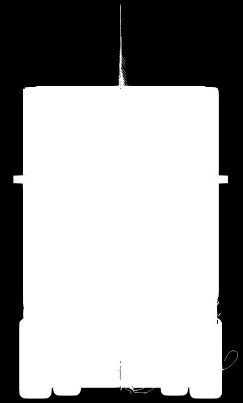
4 3D model The images below summarize the 3D model you have uploaded for the calculation. We ve analyzed it into the following key figures Model details Length [m] Width [m] 2.72 Height [m] 3.96 Frontal surface A [m²] 9.74 Views 3D view Top view 4

5 Side view Front view 5
 and friction drag (sliding over the surface). In most cases (at speeds < 300 km/h) the pressure drag is dominant.")
6 Drag Drag, or air resistance, is the force of the wind on an object in the direction of the wind. It is composed of pressure drag (pushing/pulling normal the surface) and friction drag (sliding over the surface). In most cases (at speeds < 300 km/h) the pressure drag is dominant. Drag coefficient The drag coefficient is a dimensionless quantity that indicates the aerodynamic resistance of an object moving through the air. It is defined as follows: C d = 2F d ρv²a The scale below illustrates typical C d values (NASA and Wikipedia). More streamlined objects will have a low C d, less streamlines objects will have a high C d. The C d of your project has been indicated as well. Please note that this is an indicative figure, mainly suited for comparing different concepts on the AirShaper platform. For a highly accurate value, contact us at info@airshaper.com. YOUR PROJECT: 0.35 Drag force and power versus velocity The C d provides a measure for the aerodynamic efficiency of an object. By approximation, the actual drag force F d on the object as well as the power required to propel it will vary in function of the wind speed according the following formulae: F d = ρv²c da 2 P = F d v For your project, that leads to the force & power curves shown below. Please keep in mind that this curve is an estimation, based on extrapolation from the simulation wind speed. For more accurate forces at a given velocity, please perform a simulation for that velocity. YOUR PROJECT: 1304 N YOUR PROJECT: 32.6 kw 6


7 Sources of drag underpressure Underpressure zones are areas with a pressure lower than that of the local surrounding air. Often these zones are caused by abrupt changes in shape, most pronounced at abrupt changes in cross section or surface geometry. Smooth these out to lower drag. The images below provide insight into which features of your object are causing drag by showing clouds of low pressure. The darker the cloud, the more significant the cause of drag. Top view Front view 7

8 Side view 3D view 8
, for example")


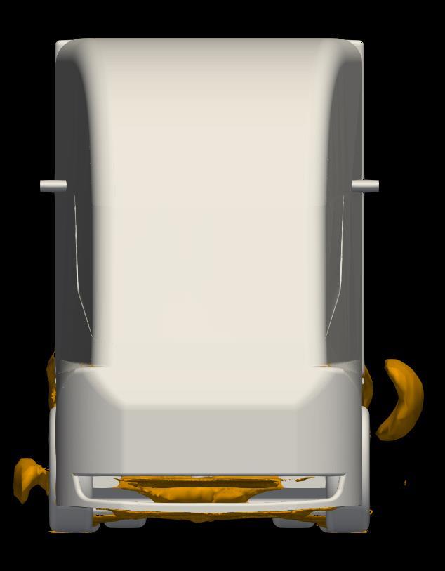
9 Sources of drag overpressure Air impacts the object and this creates overpressure. The highest pressure is reached when the air comes to a complete standstill (with respect to the object), for example at the tip of a rocket. It s called the stagnation point and the pressure at that location is the stagnation pressure. The more perpendicular a forward-facing surface is to the flow, the more likely it will create overpressure and thus drag. Likewise, a backward-facing surface experiencing underpressure will pull the object backwards, again creating drag. Try to reduce peaks in overpressure and underpressure by smoothing the surface at peak locations, critical transitions etc. to recude drag. Top view Side view 9

10 Front view 3D view 10
 can reduce friction drag.")

, you will see rather straight streamlines and at least some")
11 Sources drag surface friction Friction drag is caused by air sliding across the surface, generating friction in the process. The faster the air moves along a surface, the higher the friction force. A smooth surface (a coating with low roughness for example) can reduce friction drag. The images below show the friction drag, mapped in color on the surface of your object. Although friction drag typically contributes only a small amount to the total drag, it might be worth to try and re-route some of the air to reduce it. Also shown are streamlines, showing the pattern followed when air moves across the surface. This allows you to find locations where detachment occurs: as long as the flow is able to follow the surface (attached flow), you will see rather straight streamlines and at least some shear (color green to red) force associated with it. Once the flow detaches, it will start to swirl (curly streamlines) and move slower with respect to the surface (lower shear forces color towards blue). To optimize airflow, look at these detachment spots and try to make transitions & angles smoother. Top view Side view 11

12 Front view 3D front 12
 in the air, upstream of the object, as illustrated below (image courtesy of Paul Selhi).")

.")
13 Wind flow patterns Understanding the way the wind flows past your object is the basis for optimizing your design. In physical wind tunnels, this is often done by releasing smoke (small oil droplets) in the air, upstream of the object, as illustrated below (image courtesy of Paul Selhi). These streamlines can provide multiple insights. First of all, it allows to spot laminar flow zones (steady streamlines) and turbulent zones (swirling streamlines). The transition from laminar to turbulent often occurs when the airflow is unable to follow the surface of the object, because the negative angle of the surface is too large or because of a geometrical disturbance in the surface. This is called separation which, in most cases, increases drag. Another observation is the compression and expansion of these streamlines (the density of the streamlines). As the air can be considered as incompressible at speeds below 300 km/h, the air needs to speed up when the available cross section narrows. Speeding up and slowing down air, by changes in geometry / cross section, can again be a source of drag. Reducing these changes in velocity, by smoothing these geometry / cross section changes, can reduce drag. In the virtual world, the streamlines can be colored by the velocity, allowing to detect increases/decreases in velocity directly and not just via streamline density. The images below show the streamlines (the trajectory a weightless particle would follow when released in the air) both for a vertical and horizontal array of smoke sources. A second, more advanced visualization technique in physical wind tunnels is to light up a 2D plane with a laser and film it from a direction perpendicular to this plane (see images above courtesy of Flanders Bike Valley and formula1-dictionary.net). This makes it possible to detect in-plane movement patterns of particles. This is shown in the second series of images, 2D flow patterns, colored by velocity and by pressure. 13


14 Vertical set of streamlines Top view Side view 14

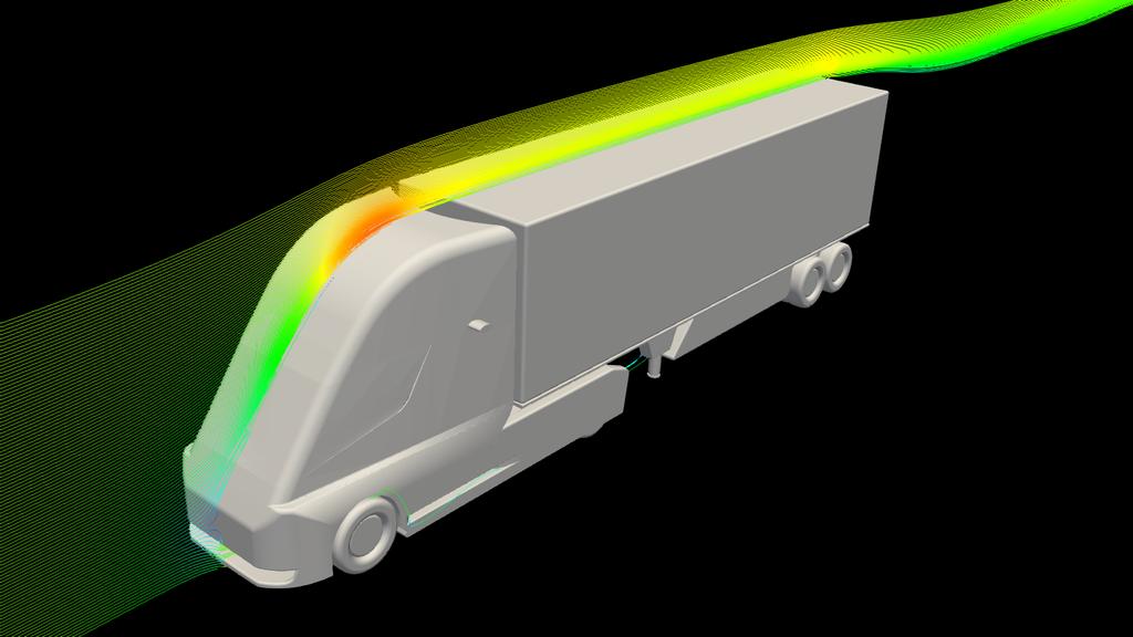
15 Front view 3D view 15


16 Horizontal set of streamlines Top view Side view 16

17 Front view 3D view 17


18 2D flow patterns - velocity Top view Side view 18


19 2D flow patterns - pressure Top view Side view 19
 have been introduced to obtain a rough estimation of the local noise generation without")

20 Noise Noise estimation by means of simulations is an advanced field of engineering. Therefore, more simplified models ( acoustic analogies ) have been introduced to obtain a rough estimation of the local noise generation without going through prohibitively expensive simulations. To reduce the noise generation in your design, look for the origin of these noise clouds in the images below. Typically, noise is generated slightly downstream of the location where the flow is disturbed. Smoothen the source and you can reduce noise generation. Avoid cavities and external parts. Top view Bottom view 20

21 Side view Front view 21

22 3D view 22
Introduction to ANSYS CFX
 Workshop 03 Fluid flow around the NACA0012 Airfoil 16.0 Release Introduction to ANSYS CFX 2015 ANSYS, Inc. March 13, 2015 1 Release 16.0 Workshop Description: The flow simulated is an external aerodynamics
THE APPLICATION OF AN ATMOSPHERIC BOUNDARY LAYER TO EVALUATE TRUCK AERODYNAMICS IN CFD
 THE APPLICATION OF AN ATMOSPHERIC BOUNDARY LAYER TO EVALUATE TRUCK AERODYNAMICS IN CFD A SOLUTION FOR A REAL-WORLD ENGINEERING PROBLEM Ir. Niek van Dijk DAF Trucks N.V. CONTENTS Scope & Background Theory:
Team 194: Aerodynamic Study of Airflow around an Airfoil in the EGI Cloud
 Team 194: Aerodynamic Study of Airflow around an Airfoil in the EGI Cloud CFD Support s OpenFOAM and UberCloud Containers enable efficient, effective, and easy access and use of MEET THE TEAM End-User/CFD
Chapter 4: Immersed Body Flow [pp (8e), or (9e)]
![Chapter 4: Immersed Body Flow [pp (8e), or (9e)]](/thumbs/91/104697741.jpg "Chapter 4: Immersed Body Flow [pp (8e), or (9e)]") Chapter 4: Immersed Body Flow [pp. 445-459 (8e), or 374-386 (9e)] Dr. Bing-Chen Wang Dept. of Mechanical Engineering Univ. of Manitoba, Winnipeg, MB, R3T 5V6 When a viscous fluid flow passes a solid body
Chapter 4: Immersed Body Flow [pp. 445-459 (8e), or 374-386 (9e)] Dr. Bing-Chen Wang Dept. of Mechanical Engineering Univ. of Manitoba, Winnipeg, MB, R3T 5V6 When a viscous fluid flow passes a solid body
CIBSE Application Manual AM11 Building Performance Modelling Chapter 6: Ventilation Modelling
 Contents Background Ventilation modelling tool categories Simple tools and estimation techniques Analytical methods Zonal network methods Computational Fluid Dynamics (CFD) Semi-external spaces Summary
SolidWorks Flow Simulation 2014
 An Introduction to SolidWorks Flow Simulation 2014 John E. Matsson, Ph.D. SDC PUBLICATIONS Better Textbooks. Lower Prices. www.sdcpublications.com Powered by TCPDF (www.tcpdf.org) Visit the following websites
F1 in Schools Car Design Simulation Tutorial
 F1 in Schools Car Design Simulation Tutorial Abstract: Gain basic understanding of simulation to quickly gain insight on the performance for drag on an F1 car. 1 P a g e Table of Contents Getting Started
An Introduction to SolidWorks Flow Simulation 2010
 An Introduction to SolidWorks Flow Simulation 2010 John E. Matsson, Ph.D. SDC PUBLICATIONS www.sdcpublications.com Schroff Development Corporation Chapter 2 Flat Plate Boundary Layer Objectives Creating
Isotropic Porous Media Tutorial
 STAR-CCM+ User Guide 3927 Isotropic Porous Media Tutorial This tutorial models flow through the catalyst geometry described in the introductory section. In the porous region, the theoretical pressure drop
DrivAer-Aerodynamic Investigations for a New Realistic Generic Car Model using ANSYS CFD
 DrivAer-Aerodynamic Investigations for a New Realistic Generic Car Model using ANSYS CFD Thomas Frank (*), BenediktGerlicher (*), Juan Abanto (**) (*) ANSYS Germany, Otterfing, Germany (**) ANSYS Inc.,
Aerodynamic Study of a Realistic Car W. TOUGERON
 Aerodynamic Study of a Realistic Car W. TOUGERON Tougeron CFD Engineer 2016 Abstract This document presents an aerodynamic CFD study of a realistic car geometry. The aim is to demonstrate the efficiency
ANSYS AIM Tutorial Turbulent Flow Over a Backward Facing Step
 ANSYS AIM Tutorial Turbulent Flow Over a Backward Facing Step Author(s): Sebastian Vecchi, ANSYS Created using ANSYS AIM 18.1 Problem Specification Pre-Analysis & Start Up Governing Equation Start-Up Geometry
COMPUTATIONAL FLUID DYNAMICS ANALYSIS OF ORIFICE PLATE METERING SITUATIONS UNDER ABNORMAL CONFIGURATIONS
 COMPUTATIONAL FLUID DYNAMICS ANALYSIS OF ORIFICE PLATE METERING SITUATIONS UNDER ABNORMAL CONFIGURATIONS Dr W. Malalasekera Version 3.0 August 2013 1 COMPUTATIONAL FLUID DYNAMICS ANALYSIS OF ORIFICE PLATE
Compressible Flow in a Nozzle
 SPC 407 Supersonic & Hypersonic Fluid Dynamics Ansys Fluent Tutorial 1 Compressible Flow in a Nozzle Ahmed M Nagib Elmekawy, PhD, P.E. Problem Specification Consider air flowing at high-speed through a
NUMERICAL 3D TRANSONIC FLOW SIMULATION OVER A WING
 Review of the Air Force Academy No.3 (35)/2017 NUMERICAL 3D TRANSONIC FLOW SIMULATION OVER A WING Cvetelina VELKOVA Department of Technical Mechanics, Naval Academy Nikola Vaptsarov,Varna, Bulgaria (cvetelina.velkova1985@gmail.com)
Modeling Evaporating Liquid Spray
 Tutorial 16. Modeling Evaporating Liquid Spray Introduction In this tutorial, FLUENT s air-blast atomizer model is used to predict the behavior of an evaporating methanol spray. Initially, the air flow
Dimensioning and Airflow Simulation of the Wing of an Ultralight Aircraft
 Dimensioning and Airflow Simulation of the Wing of an Ultralight Aircraft Richárd Molnár 1 Gergely Dezső 2* Abstract: Increasing interest to ultralight aircrafts usually made of composite materials leads
Detached Eddy Simulation Analysis of a Transonic Rocket Booster for Steady & Unsteady Buffet Loads
 Detached Eddy Simulation Analysis of a Transonic Rocket Booster for Steady & Unsteady Buffet Loads Matt Knapp Chief Aerodynamicist TLG Aerospace, LLC Presentation Overview Introduction to TLG Aerospace
Computational Simulation of the Wind-force on Metal Meshes
 16 th Australasian Fluid Mechanics Conference Crown Plaza, Gold Coast, Australia 2-7 December 2007 Computational Simulation of the Wind-force on Metal Meshes Ahmad Sharifian & David R. Buttsworth Faculty
Flow Structures Extracted from Visualization Images: Vector Fields and Topology
 Flow Structures Extracted from Visualization Images: Vector Fields and Topology Tianshu Liu Department of Mechanical & Aerospace Engineering Western Michigan University, Kalamazoo, MI 49008, USA We live
Computational Domain Selection for. CFD Simulation
 Computational Domain Selection for CFD Simulation Scope of the this Presentation The guidelines are very generic in nature and has been explained with examples. However, the users may need to check their
Abstract. Die Geometry. Introduction. Mesh Partitioning Technique for Coextrusion Simulation
 OPTIMIZATION OF A PROFILE COEXTRUSION DIE USING A THREE-DIMENSIONAL FLOW SIMULATION SOFTWARE Kim Ryckebosh 1 and Mahesh Gupta 2, 3 1. Deceuninck nv, BE-8830 Hooglede-Gits, Belgium 2. Michigan Technological
Effect of Leading Edge Porosity on the Flow Field of an Air Launched Grenade
 Effect of Leading Edge Porosity on the Flow Field of an Air Launched Grenade Zachary M. Hall Aerospace Engineering Department Auburn University, AL 36849 Abstract Reported are the results of experiments
Backward facing step Homework. Department of Fluid Mechanics. For Personal Use. Budapest University of Technology and Economics. Budapest, 2010 autumn
 Backward facing step Homework Department of Fluid Mechanics Budapest University of Technology and Economics Budapest, 2010 autumn Updated: October 26, 2010 CONTENTS i Contents 1 Introduction 1 2 The problem
Ch. 25 The Reflection of Light
 Ch. 25 The Reflection of Light 25. Wave fronts and rays We are all familiar with mirrors. We see images because some light is reflected off the surface of the mirror and into our eyes. In order to describe
THE EFFECTS OF THE PLANFORM SHAPE ON DRAG POLAR CURVES OF WINGS: FLUID-STRUCTURE INTERACTION ANALYSES RESULTS
 March 18-20, 2013 THE EFFECTS OF THE PLANFORM SHAPE ON DRAG POLAR CURVES OF WINGS: FLUID-STRUCTURE INTERACTION ANALYSES RESULTS Authors: M.R. Chiarelli, M. Ciabattari, M. Cagnoni, G. Lombardi Speaker:
MAE 3130: Fluid Mechanics Lecture 5: Fluid Kinematics Spring Dr. Jason Roney Mechanical and Aerospace Engineering
 MAE 3130: Fluid Mechanics Lecture 5: Fluid Kinematics Spring 2003 Dr. Jason Roney Mechanical and Aerospace Engineering Outline Introduction Velocity Field Acceleration Field Control Volume and System Representation
STAR-CCM+ User Guide 6922
 STAR-CCM+ User Guide 6922 Introduction Welcome to the STAR-CCM+ introductory tutorial. In this tutorial, you explore the important concepts and workflow. Complete this tutorial before attempting any others.
SPC 307 Aerodynamics. Lecture 1. February 10, 2018
 SPC 307 Aerodynamics Lecture 1 February 10, 2018 Sep. 18, 2016 1 Course Materials drahmednagib.com 2 COURSE OUTLINE Introduction to Aerodynamics Review on the Fundamentals of Fluid Mechanics Euler and
Flow Field of Truncated Spherical Turrets
 Flow Field of Truncated Spherical Turrets Kevin M. Albarado 1 and Amelia Williams 2 Aerospace Engineering, Auburn University, Auburn, AL, 36849 Truncated spherical turrets are used to house cameras and
International Power, Electronics and Materials Engineering Conference (IPEMEC 2015)
") International Power, Electronics and Materials Engineering Conference (IPEMEC 2015) Numerical Simulation of the Influence of Intake Grille Shape on the Aerodynamic Performance of a Passenger Car Longwei
International Power, Electronics and Materials Engineering Conference (IPEMEC 2015) Numerical Simulation of the Influence of Intake Grille Shape on the Aerodynamic Performance of a Passenger Car Longwei
4.5 Conservative Forces
 4 CONSERVATION LAWS 4.5 Conservative Forces Name: 4.5 Conservative Forces In the last activity, you looked at the case of a block sliding down a curved plane, and determined the work done by gravity as
Transportation Engineering - II Dr.Rajat Rastogi Department of Civil Engineering Indian Institute of Technology - Roorkee
 Transportation Engineering - II Dr.Rajat Rastogi Department of Civil Engineering Indian Institute of Technology - Roorkee Lecture 18 Vertical Curves and Gradients Dear students, I welcome you back to the
VALIDATION OF FLOEFD AUTOMOTIVE AERODYNAMIC CAPABILITIES USING DRIVAER TEST MODEL
 VALIDATION OF FLOEFD AUTOMOTIVE AERODYNAMIC CAPABILITIES USING DRIVAER TEST MODEL MAXIM VOLYNKIN, ANDREY IVANOV, GENNADY DUMNOV MENTOR - A SIEMENS BUSINESS, MECHANICAL ANALYSIS DIVISION, MOSCOW, RUSSIA
First Steps - Ball Valve Design
 COSMOSFloWorks 2004 Tutorial 1 First Steps - Ball Valve Design This First Steps tutorial covers the flow of water through a ball valve assembly before and after some design changes. The objective is to
Verification of Laminar and Validation of Turbulent Pipe Flows
 1 Verification of Laminar and Validation of Turbulent Pipe Flows 1. Purpose ME:5160 Intermediate Mechanics of Fluids CFD LAB 1 (ANSYS 18.1; Last Updated: Aug. 1, 2017) By Timur Dogan, Michael Conger, Dong-Hwan
Numerical Modeling Study for Fish Screen at River Intake Channel ; PH (505) ; FAX (505) ;
 ; FAX (505) ;") Numerical Modeling Study for Fish Screen at River Intake Channel Jungseok Ho 1, Leslie Hanna 2, Brent Mefford 3, and Julie Coonrod 4 1 Department of Civil Engineering, University of New Mexico, Albuquerque,
Numerical Modeling Study for Fish Screen at River Intake Channel Jungseok Ho 1, Leslie Hanna 2, Brent Mefford 3, and Julie Coonrod 4 1 Department of Civil Engineering, University of New Mexico, Albuquerque,
TUTORIAL#4. Marek Jaszczur. Turbulent Thermal Boundary Layer on a Flat Plate W1-1 AGH 2018/2019
 TUTORIAL#4 Turbulent Thermal Boundary Layer on a Flat Plate Marek Jaszczur AGH 2018/2019 W1-1 Problem specification TUTORIAL#4 Turbulent Thermal Boundary Layer - on a flat plate Goal: Solution for Non-isothermal
Computational Fluid Dynamics (CFD) for Built Environment
 for Built Environment") Computational Fluid Dynamics (CFD) for Built Environment Seminar 4 (For ASHRAE Members) Date: Sunday 20th March 2016 Time: 18:30-21:00 Venue: Millennium Hotel Sponsored by: ASHRAE Oryx Chapter Dr. Ahmad
Computational Fluid Dynamics (CFD) for Built Environment Seminar 4 (For ASHRAE Members) Date: Sunday 20th March 2016 Time: 18:30-21:00 Venue: Millennium Hotel Sponsored by: ASHRAE Oryx Chapter Dr. Ahmad
Modeling Evaporating Liquid Spray
 Tutorial 17. Modeling Evaporating Liquid Spray Introduction In this tutorial, the air-blast atomizer model in ANSYS FLUENT is used to predict the behavior of an evaporating methanol spray. Initially, the
The viscous forces on the cylinder are proportional to the gradient of the velocity field at the
 Fluid Dynamics Models : Flow Past a Cylinder Flow Past a Cylinder Introduction The flow of fluid behind a blunt body such as an automobile is difficult to compute due to the unsteady flows. The wake behind
Computational Flow Analysis of Para-rec Bluff Body at Various Reynold s Number
 International Journal of Engineering Research and Technology. ISSN 0974-3154 Volume 6, Number 5 (2013), pp. 667-674 International Research Publication House http://www.irphouse.com Computational Flow Analysis
CFD Analysis of a Fully Developed Turbulent Flow in a Pipe with a Constriction and an Obstacle
 CFD Analysis of a Fully Developed Turbulent Flow in a Pipe with a Constriction and an Obstacle C, Diyoke Mechanical Engineering Department Enugu State University of Science & Tech. Enugu, Nigeria U, Ngwaka
Vector Visualization. CSC 7443: Scientific Information Visualization
 Vector Visualization Vector data A vector is an object with direction and length v = (v x,v y,v z ) A vector field is a field which associates a vector with each point in space The vector data is 3D representation
Transition Flow and Aeroacoustic Analysis of NACA0018 Satish Kumar B, Fred Mendonç a, Ghuiyeon Kim, Hogeon Kim
 Transition Flow and Aeroacoustic Analysis of NACA0018 Satish Kumar B, Fred Mendonç a, Ghuiyeon Kim, Hogeon Kim Transition Flow and Aeroacoustic Analysis of NACA0018 Satish Kumar B, Fred Mendonç a, Ghuiyeon
Using wind tunnel tests to study pressure distributions around a bluff body: the case of a circular cylinder
 World Transactions on Engineering and Technology Education Vol.8, No.3, 010 010 WIETE Using wind tunnel tests to study pressure distributions around a bluff body: the case of a circular cylinder Josué
iric Software Changing River Science River2D Tutorials
 iric Software Changing River Science River2D Tutorials iric Software Changing River Science Confluence of the Colorado River, Blue River and Indian Creek, Colorado, USA 1 TUTORIAL 1: RIVER2D STEADY SOLUTION
Second Symposium on Hybrid RANS-LES Methods, 17/18 June 2007
 1 Zonal-Detached Eddy Simulation of Transonic Buffet on a Civil Aircraft Type Configuration V.BRUNET and S.DECK Applied Aerodynamics Department The Buffet Phenomenon Aircraft in transonic conditions Self-sustained
TUTORIAL#3. Marek Jaszczur. Boundary Layer on a Flat Plate W1-1 AGH 2018/2019
 TUTORIAL#3 Boundary Layer on a Flat Plate Marek Jaszczur AGH 2018/2019 W1-1 Problem specification TUTORIAL#3 Boundary Layer - on a flat plate Goal: Solution for boudary layer 1. Creating 2D simple geometry
Application of Wray-Agarwal Turbulence Model for Accurate Numerical Simulation of Flow Past a Three-Dimensional Wing-body
 Washington University in St. Louis Washington University Open Scholarship Mechanical Engineering and Materials Science Independent Study Mechanical Engineering & Materials Science 4-28-2016 Application
McNair Scholars Research Journal
 McNair Scholars Research Journal Volume 2 Article 1 2015 Benchmarking of Computational Models against Experimental Data for Velocity Profile Effects on CFD Analysis of Adiabatic Film-Cooling Effectiveness
CFD Post-Processing of Rampressor Rotor Compressor
 Gas Turbine Industrial Fellowship Program 2006 CFD Post-Processing of Rampressor Rotor Compressor Curtis Memory, Brigham Young niversity Ramgen Power Systems Mentor: Rob Steele I. Introduction Recent movements
Simulation and Validation of Turbulent Pipe Flows
 Simulation and Validation of Turbulent Pipe Flows ENGR:2510 Mechanics of Fluids and Transport Processes CFD LAB 1 (ANSYS 17.1; Last Updated: Oct. 10, 2016) By Timur Dogan, Michael Conger, Dong-Hwan Kim,
Estimating Vertical Drag on Helicopter Fuselage during Hovering
 Estimating Vertical Drag on Helicopter Fuselage during Hovering A. A. Wahab * and M.Hafiz Ismail ** Aeronautical & Automotive Dept., Faculty of Mechanical Engineering, Universiti Teknologi Malaysia, 81310
9.9 Coherent Structure Detection in a Backward-Facing Step Flow
 9.9 Coherent Structure Detection in a Backward-Facing Step Flow Contributed by: C. Schram, P. Rambaud, M. L. Riethmuller 9.9.1 Introduction An algorithm has been developed to automatically detect and characterize
RBF Morph An Add-on Module for Mesh Morphing in ANSYS Fluent
 RBF Morph An Add-on Module for Mesh Morphing in ANSYS Fluent Gilles Eggenspieler Senior Product Manager 1 Morphing & Smoothing A mesh morpher is a tool capable of performing mesh modifications in order
Simulation of Laminar Pipe Flows
 Simulation of Laminar Pipe Flows 57:020 Mechanics of Fluids and Transport Processes CFD PRELAB 1 By Timur Dogan, Michael Conger, Maysam Mousaviraad, Tao Xing and Fred Stern IIHR-Hydroscience & Engineering
Photoresist with Ultrasonic Atomization Allows for High-Aspect-Ratio Photolithography under Atmospheric Conditions
 Photoresist with Ultrasonic Atomization Allows for High-Aspect-Ratio Photolithography under Atmospheric Conditions 1 CONTRIBUTING AUTHORS Robb Engle, Vice President of Engineering, Sono-Tek Corporation
Computation of Velocity, Pressure and Temperature Distributions near a Stagnation Point in Planar Laminar Viscous Incompressible Flow
 Excerpt from the Proceedings of the COMSOL Conference 8 Boston Computation of Velocity, Pressure and Temperature Distributions near a Stagnation Point in Planar Laminar Viscous Incompressible Flow E. Kaufman
Introduction to CFX. Workshop 2. Transonic Flow Over a NACA 0012 Airfoil. WS2-1. ANSYS, Inc. Proprietary 2009 ANSYS, Inc. All rights reserved.
 Workshop 2 Transonic Flow Over a NACA 0012 Airfoil. Introduction to CFX WS2-1 Goals The purpose of this tutorial is to introduce the user to modelling flow in high speed external aerodynamic applications.
STAR-CCM+: Ventilation SPRING Notes on the software 2. Assigned exercise (submission via Blackboard; deadline: Thursday Week 9, 11 pm)
") STAR-CCM+: Ventilation SPRING 208. Notes on the software 2. Assigned exercise (submission via Blackboard; deadline: Thursday Week 9, pm). Features of the Exercise Natural ventilation driven by localised
STAR-CCM+: Ventilation SPRING 208. Notes on the software 2. Assigned exercise (submission via Blackboard; deadline: Thursday Week 9, pm). Features of the Exercise Natural ventilation driven by localised
AERODYNAMIC ANALYSIS OF PERSONAL VEHICLE SIDE MIRROR
 Journal of Engineering Science and Technology 7 th EURECA 2016 Special Issue July (2018) 52-64 School of Engineering, Taylor s University AERODYNAMIC ANALYSIS OF PERSONAL VEHICLE SIDE MIRROR ABDULKAREEM
ANSYS FLUENT. Airfoil Analysis and Tutorial
 ANSYS FLUENT Airfoil Analysis and Tutorial ENGR083: Fluid Mechanics II Terry Yu 5/11/2017 Abstract The NACA 0012 airfoil was one of the earliest airfoils created. Its mathematically simple shape and age
Detached-Eddy Simulation of a Linear Compressor Cascade with Tip Gap and Moving Wall *)
") FOI, Stockholm, Sweden 14-15 July, 2005 Detached-Eddy Simulation of a Linear Compressor Cascade with Tip Gap and Moving Wall *) A. Garbaruk,, M. Shur, M. Strelets, and A. Travin *) Study is carried out
FOI, Stockholm, Sweden 14-15 July, 2005 Detached-Eddy Simulation of a Linear Compressor Cascade with Tip Gap and Moving Wall *) A. Garbaruk,, M. Shur, M. Strelets, and A. Travin *) Study is carried out
Design and Development of Unmanned Tilt T-Tri Rotor Aerial Vehicle
 Design and Development of Unmanned Tilt T-Tri Rotor Aerial Vehicle K. Senthil Kumar, Mohammad Rasheed, and T.Anand Abstract Helicopter offers the capability of hover, slow forward movement, vertical take-off
Recent & Upcoming Features in STAR-CCM+ for Aerospace Applications Deryl Snyder, Ph.D.
 Recent & Upcoming Features in STAR-CCM+ for Aerospace Applications Deryl Snyder, Ph.D. Outline Introduction Aerospace Applications Summary New Capabilities for Aerospace Continuity Convergence Accelerator
WONG HSI, J. J. MIAU,
 Flow Separation Control with a Truncated Ellipse Airfoil in Cycling Aerodynamics WONG HSI, J. J. MIAU Department of Aeronautics and Astronautics (DAA), National Cheng Kung University, Tainan, Taiwan (R.O.C)
Calculate a solution using the pressure-based coupled solver.
 Tutorial 19. Modeling Cavitation Introduction This tutorial examines the pressure-driven cavitating flow of water through a sharpedged orifice. This is a typical configuration in fuel injectors, and brings
NUMERICAL SIMULATION OF LOCAL LOSS COEFFICIENTS OF VENTILATION DUCT FITTINGS
 Eleventh International IBPSA Conference Glasgow, Scotland July 7-30, 009 NUMERICAL SIMULATION OF LOCAL LOSS COEFFICIENTS OF VENTILATION DUCT FITTINGS Vladimir Zmrhal, Jan Schwarzer Department of Environmental
INVESTIGATION OF FLOW BEHAVIOR PASSING OVER A CURVETURE STEP WITH AID OF PIV SYSTEM
 INVESTIGATION OF FLOW BEHAVIOR PASSING OVER A CURVETURE STEP WITH AID OF PIV SYSTEM Noor Y. Abbas Department of Mechanical Engineering, Al Nahrain University, Baghdad, Iraq E-Mail: noor13131979@gmail.com
1. Interpreting the Results: Visualization 1
 1. Interpreting the Results: Visualization 1 visual/graphical/optical representation of large sets of data: data from experiments or measurements: satellite images, tomography in medicine, microsopy,...
High-Lift Aerodynamics: STAR-CCM+ Applied to AIAA HiLiftWS1 D. Snyder
 High-Lift Aerodynamics: STAR-CCM+ Applied to AIAA HiLiftWS1 D. Snyder Aerospace Application Areas Aerodynamics Subsonic through Hypersonic Aeroacoustics Store release & weapons bay analysis High lift devices
Measurements in Fluid Mechanics
 Measurements in Fluid Mechanics 13.1 Introduction The purpose of this chapter is to provide the reader with a basic introduction to the concepts and techniques applied by engineers who measure flow parameters
Express Introductory Training in ANSYS Fluent Workshop 04 Fluid Flow Around the NACA0012 Airfoil
 Express Introductory Training in ANSYS Fluent Workshop 04 Fluid Flow Around the NACA0012 Airfoil Dimitrios Sofialidis Technical Manager, SimTec Ltd. Mechanical Engineer, PhD PRACE Autumn School 2013 -
STAR-CCM+: Wind loading on buildings SPRING 2018
 STAR-CCM+: Wind loading on buildings SPRING 2018 1. Notes on the software 2. Assigned exercise (submission via Blackboard; deadline: Thursday Week 3, 11 pm) 1. NOTES ON THE SOFTWARE STAR-CCM+ generates
Bicycle frame shape and the effect on performance
 University of Arkansas, Fayetteville ScholarWorks@UARK Mechanical Engineering Undergraduate Honors Theses Mechanical Engineering 5-2013 Bicycle frame shape and the effect on performance Connor McWilliams
Steady Flow: Lid-Driven Cavity Flow
 STAR-CCM+ User Guide Steady Flow: Lid-Driven Cavity Flow 2 Steady Flow: Lid-Driven Cavity Flow This tutorial demonstrates the performance of STAR-CCM+ in solving a traditional square lid-driven cavity
Physical or wave optics
 Physical or wave optics In the last chapter, we have been studying geometric optics u light moves in straight lines u can summarize everything by indicating direction of light using a ray u light behaves
Vector Field Visualization: Introduction
 Vector Field Visualization: Introduction What is a Vector Field? Why It is Important? Vector Fields in Engineering and Science Automotive design [Chen et al. TVCG07,TVCG08] Weather study [Bhatia and Chen
AERO-VIBRO-ACOUSTIC NOISE PREDICTION FOR HIGH SPEED ELEVATORS
 AERO-VIBRO-ACOUSTIC NOISE PREDICTION FOR HIGH SPEED ELEVATORS Antti Lehtinen 1, Gabriela Roivainen 2, Jukka Tanttari 3, Jaakko Ylätalo 1 1 FS Dynamics Finland Hermiankatu 1 33720 Tampere antti.lehtinen@fsdynamics.fi
Introduction to C omputational F luid Dynamics. D. Murrin
 Introduction to C omputational F luid Dynamics D. Murrin Computational fluid dynamics (CFD) is the science of predicting fluid flow, heat transfer, mass transfer, chemical reactions, and related phenomena
Development of Hybrid Fluid Jet / Float Polishing Process
 COMSOL Conference - Tokyo 2013 Development of Hybrid Fluid Jet / Float Polishing Process A. Beaucamp, Y. Namba Dept. of Mechanical Engineering, Chubu University, Japan Zeeko LTD, United Kingdom Research
Modelling wind driven airflow rate with CFD and verification of. approximation formulas based on wind pressure coefficients
 Modelling wind driven airflow rate with CFD and verification of approximation formulas based on wind pressure coefficients S. Leenknegt 1 *, B. Piret 1, A. Tablada de la Torre 1, D. Saelens 1 (1) Division
Extension and Validation of the CFX Cavitation Model for Sheet and Tip Vortex Cavitation on Hydrofoils
 Extension and Validation of the CFX Cavitation Model for Sheet and Tip Vortex Cavitation on Hydrofoils C. Lifante, T. Frank, M. Kuntz ANSYS Germany, 83624 Otterfing Conxita.Lifante@ansys.com 2006 ANSYS,
Convection Cooling of Circuit Boards 3D Natural Convection
 Convection Cooling of Circuit Boards 3D Natural Convection Introduction This example models the air cooling of circuit boards populated with multiple integrated circuits (ICs), which act as heat sources.
Numerical calculation of the wind action on buildings using Eurocode 1 atmospheric boundary layer velocity profiles
 Numerical calculation of the wind action on buildings using Eurocode 1 atmospheric boundary layer velocity profiles M. F. P. Lopes IDMEC, Instituto Superior Técnico, Av. Rovisco Pais 149-1, Lisboa, Portugal
Verification and Validation of Turbulent Flow around a Clark-Y Airfoil
 Verification and Validation of Turbulent Flow around a Clark-Y Airfoil 1. Purpose 58:160 Intermediate Mechanics of Fluids CFD LAB 2 By Tao Xing and Fred Stern IIHR-Hydroscience & Engineering The University
4. RHEOELECTRIC ANALOGY
 4. RHEOELECTRIC ANALOGY 4.1 Rheoelectric tank for transonic flow analogy The structure of the particular solutions used for the illustrated examples gives information also about the details of the mapping
ON INVESTIGATING THE C-TRANSITION CURVE FOR NOISE REDUCTION
 On Investigating The C-Transition Curve for Noise Reduction ON INVESTIGATING THE C-TRANSITION CURVE FOR NOISE REDUCTION Azma Putra 1*, Or Khai Hee 2, Saifudin Hafiz Yahaya 3 1,2 Faculty of Mechanical Engineering,
Middle East Technical University Mechanical Engineering Department ME 485 CFD with Finite Volume Method Fall 2017 (Dr. Sert)
") Middle East Technical University Mechanical Engineering Department ME 485 CFD with Finite Volume Method Fall 2017 (Dr. Sert) ANSYS Fluent Tutorial Developing Laminar Flow in a 2D Channel 1 How to use This
Middle East Technical University Mechanical Engineering Department ME 485 CFD with Finite Volume Method Fall 2017 (Dr. Sert) ANSYS Fluent Tutorial Developing Laminar Flow in a 2D Channel 1 How to use This
GLASGOW 2003 INTEGRATING CFD AND EXPERIMENT
 GLASGOW 2003 INTEGRATING CFD AND EXPERIMENT A Detailed CFD and Experimental Investigation of a Benchmark Turbulent Backward Facing Step Flow Stephen Hall & Tracie Barber University of New South Wales Sydney,
Numerical Analysis of the Bleed Slot Design of the Purdue Mach 6 Wind Tunnel
 43rd AIAA Aerospace Sciences Meeting and Exhibit, Jan 10 13, Reno, Nevada Numerical Analysis of the Bleed Slot Design of the Purdue Mach 6 Wind Tunnel Ezgi S. Taskinoglu and Doyle D. Knight Dept of Mechanical
Direct Numerical Simulation of a Low Pressure Turbine Cascade. Christoph Müller
 Low Pressure NOFUN 2015, Braunschweig, Overview PostProcessing Experimental test facility Grid generation Inflow turbulence Conclusion and slide 2 / 16 Project Scale resolving Simulations give insight
The Standard Module - Ventilation Systems
 Chapter 3 The Standard Module - Ventilation Systems 3.1 Introduction The PIPENET Vision Standard module is a tool for steady state flow modelling of networks of pipes and ducts. It can model incompressible
NUMERICAL MODELING STUDY FOR FLOW PATTERN CHANGES INDUCED BY SINGLE GROYNE
 NUMERICAL MODELING STUDY FOR FLOW PATTERN CHANGES INDUCED BY SINGLE GROYNE Jungseok Ho 1, Hong Koo Yeo 2, Julie Coonrod 3, and Won-Sik Ahn 4 1 Research Assistant Professor, Dept. of Civil Engineering,
NUMERICAL ANALYSIS OF WIND EFFECT ON HIGH-DENSITY BUILDING AERAS
 NUMERICAL ANALYSIS OF WIND EFFECT ON HIGH-DENSITY BUILDING AERAS Bin ZHAO, Ying LI, Xianting LI and Qisen YAN Department of Thermal Engineering, Tsinghua University Beijing, 100084, P.R. China ABSTRACT
Effect of Yaw Angle on Drag Over Clean Rectangular Cavities
 ISSN (e): 2250 3005 Volume, 07 Issue, 08 August 2017 International Journal of Computational Engineering Research (IJCER) Effect of Yaw Angle on Drag Over Clean Rectangular Cavities * Dhaval Shiyani 1,
How to Enter and Analyze a Wing
 How to Enter and Analyze a Wing Entering the Wing The Stallion 3-D built-in geometry creation tool can be used to model wings and bodies of revolution. In this example, a simple rectangular wing is modeled
Numerical analysis of fluid flow inside air intake system
 Numerical analysis of fluid flow inside air intake system Numerical analysis of fluid flow inside air intake system Regis Ataides Martin Kessler Marcelo Kruger Geraldo Severi Jr. Cesareo de La Rosa Siqueira
Vehicle Cabin Noise from Turbulence Induced by Side-View Mirrors. Hua-Dong Yao, 2018/8/29 Chalmers University of Technology, Sweden
 Vehicle Cabin Noise from Turbulence Induced by Side-View Mirrors Hua-Dong Yao, 2018/8/29 Chalmers University of Technology, Sweden An Important Cabin Noise Source Turbulence As the development of quiet