User Interface Introduction... 4 User Interface - Main Menu... 5 User Interface - Tool Bar... 6 File Handlers... 7 Edit Controls... 8 Indicators...
|
|
|
- Harry Allison
- 6 years ago
- Views:
Transcription
1
2 User Interface Introduction... 4 User Interface - Main Menu... 5 User Interface - Tool Bar... 6 File Handlers... 7 Edit Controls... 8 Indicators Lights Pixel Shader User Interface - Scene Tree Components of Node Node Types Renaming Nodes Selecting Nodes Including and Excluding Mesh Nodes User Interface - Preview Window Play Control Panel User Interface - Modify Page Pipelines Converting Model to Static 3D Prop Converting Model with Animations to iprop Converting Bone-Skinned Models to Avatars Modifying and Replacing Meshes in Models Exporting Custom Head to Head-Morphing Template Section Details in Modify Page Node Section Including and Excluding Mesh Nodes Excluding Back Faces Making and Removing Sub-Prop Transform Section Aligning Nodes Resetting Transform of Modified Model Pivot Section Pivot of Prop Relocating Pivot Normal The Concept of Normal Flipping the Normal Unifying the Normal Utilizing Flip Face Mode Auto-Smoothing Mesh Nodes Animation Section Character Section Posing Avatar for Exporting OBJ Setting Bones for Converting to Non-Human Character... 96
3 Multiple Channel Texture Mapping Types of Maps Modifying Texture Settings - Basic Modifying Texture Settings - Advanced Texture Channel UV Offset and Tiling Synchronizing Texture UV Changes to All Channels Load and Save Materials External Texture and Material Sharing Adding New Material with the Make Unique Feature UV Settings Section Model Mapping Method Export Exporting an OBJ File Exporting Props or Characters Export Options Keyboard Shortcuts

4 User Interface Introduction The user interface of 3DXchange is divided into 6 sections: 1. Main Menu 2. Tool Bar 3. Scene Tree 4. Preview Window 5. Play Control Panel 6. Modify Page

5 User Interface - Main Menu 1. File - To open, to export (.iprop, iavatar or.obj file), to link to Google 3D Warehouse web site, to edit the original SKP file, to reload file and to exit 3DXchange. 2. Edit - To undo/redo, to make sub-prop, to exclude SKP back faces, to switch to different camera view and to enable/disable two-side picking mode. 3. View - To show / hide preview information (FPS, Rendering Shader, Face Count), grid, world axis, dummy shadow, highlight (wire frame and bounding box), normal, and to enable/disable pixel shader mode. 4. Help - To invoke the Help document and about box window. Note: If the loaded model contains DRM data or DRM material, you will not be able to export it as an OBJ model file. DRM (Digital Right Management) is a protective mechanism for the official content released by Reallusion.
6 User Interface - Tool Bar 1. File Handlers 2. Edit Controls 3. Indicators 4. Lights 5. Pixel Shader
7 F I L E H A N D L E R S 1. Open (Ctrl + O) - Click to load mode or character files (.iprop,.iavatar,.vns,.fbx,.obj,.3ds,.skp). 2. Export (Ctrl + E) - Click to invoke the export dialog box. 3. Google 3D Warehouse - Click to launch the Google 3D Warehouse web site to search for models. 4. Reload (F5) - Click this button to retrieve the initial status of the currently used source file. All previously made changes will be discarded.
8 E D I T C O N T R O L S 1. Undo (Ctrl + Z)/Redo (Ctrl + Y) - You may use these two buttons to undo / redo the last modification. 2. Home (Home) - Click this button to set the camera to the initial view of the scene. 3. Camera Zoom (Z) - Press this button, drag up / down in the preview window to zoom in / out the camera. 4. Camera Pan (X) - Press this button and drag to move the camera horizontally / vertically. (Dragging with right mouse button may rotate the camera around the selected node and dragging with both mouse buttons may zoom in/out the camera view. 5. Camera Rotate (C) - Press this button to rotate the camera around the selected node or nodes. 6. Select Object (Q) - Drag in the preview window to select mesh nodes. With Ctrl key held, you may also click to select multiple mesh nodes. 7. Move Object (W) - Move selected root or parent node. 8. Rotate Object (E) - Rotate selected root or parent node. 9. Scale Object (R) - Scale selected root or parent node.
9 Tips: Press down the Shift key to accelerate the speed of Pan, Rotate and Zoom by ten times. The Move / Rotate / Scale Object tools are enabled only when the root node or single parent node is selected.
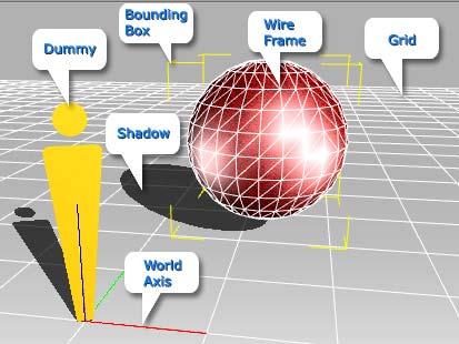
10 I N D I C A T O R S 1. 2-Side Picking - Choose this mode to enable the ability to select mesh nodes (or polygonal faces for flipping) from both their front or back (transparent) side. 2. Grid (Ctrl + G) - Press this button to show / hide the gird on the floor. The size for each grid is 100 x 100 units. 3. World Axis (Ctrl + A) - Press this button to show / hide the world axis (0, 0, 0). The Red / Green / Blue line represent the X / Y / Z axis 4. Dummy (Ctrl + D) - Press this button to show / hide a dummy (same size as the default character in iclone ) in the center of the scene as a scale reference for imported models. The dummy can neither be edited nor exported. 5. Shadow - Press this button to show / hide the shadow. 6. Show Normal - Press this button to show / hide the normal for each mesh face. 7. Wire Frame - Press this button to show / hide the wire frame of the selected node or nodes. 8. Bounding Box - Press this button to show / hide the bounding box of the selected node or nodes.
11
12 L I G H T S 1. Front Light - Toggle the light at the front.


 on the right")
13 2. Side Light - Toggle the light at the right side. 3. Full Light - Toggle three lights located evenly around the scene. 4. Color Light - Toggle two color lights (red and green) on the right and on the left side.

14 P I X E L S H A D E R Now 3DXchange is synced with the iclone4 Pixel Shader for advanced real-time material and multi-texture display. You can now preview or prepare the content in 3DXchange, and enjoy the same visual result in iclone4. The Pixel Shader (highly system-resource-consuming) mainly shows some of the texture effects, such as; bump, specular, glow and texture reflection effects. When the Pixel Shader is turned on / off (Ctrl + F1), the 3D viewer will show the Pixel Shader / Quick Shader at the top-left corner.

15 Pixel Shader OFF Pixel Shader ON Bump Effect Pixel Shader On Specular Effect Pixel Shader ON Glow Effect Pixel Shader ON Reflection Effect
16 User Interface - Scene Tree The scene tree lists all the mesh or non-mesh nodes in a scene. It mounts all the objects according to the hierarchy of the loaded files as they are exported from other 3D applications. It also shows the editable status for each object and provides check boxes for you to include/exclude mesh objects during exporting. Component of Node Node Types Renaming Nodes Selecting Nodes Including and Excluding Nodes Hiding the Excluded Nodes


17 C O M P O N E N T S O F N O D E In this section, we will describe the components of a node with illustrations. The name of these components can be seen throughout this document and other common 3D software. Vertex (Plural: Vertices) A vertex is a point in 3D space. When two or more polygonal faces share one single corner, this corner is also a vertex for all of them. Vertices of a node (points in red) Face When three or more vertices are linked by edges and form a closed space, the space is called a face. Pyramid formed by 4 faces, each face is a shape of triangle.


18 Mesh A mesh contains a collection of polygons, which can be of different types (Triangles, quads, multi-sided). Mesh house formed by polygons Pivot A pivot is a specific position used as a reference for the transformations of objects. Every object or a group of objects has a pivot point that can be moved relative to the object. Pivot is also known as "center" in some other 3D software. Please refer to Pivot Section for more information. Pivot of a ring
 data. After the object is exported to iclone, you may then see the name of the these nodes in the Scene Manager or animate it.")
19 N O D E T Y P E S There are three types of nodes shown in the scene tree. They are separated by being attached with two different icons. - This indicates that the node is a root or sub-root node. You may then modify its RTS (Rotate, Transform, Scale) data. After the object is exported to iclone, you may then see the name of the these nodes in the Scene Manager or animate it. For more information about how to make a sub-root node, please refer to the Making and Removing Sub-Prop section. - This indicates that the mesh of the node is editable. The mesh can be adjusted and replaced by means of any external 3D modeling tool, smoothed, or applied with various materials in 3DXchange. When you want to utilize the Export Selected Only in the export panel, then you must first select one or more nodes of the same kind. (Please note that if you want to modify the transform data of this kind of node, then you must first make it as a sub-node and then modify its parent's (sub-root) transform data.) - This indicates that the node contains no mesh for editing. It indicates that bone nodes or dummy nodes cannot be modified in 3DXchange. Tip: After you load a bone-skinned character, the bone nodes cannot be excluded.
20 R E N A M I N G N O D E S 3DXchange provides with a conventional method to change the node names of props. It facilitates you to recognize and organize the nodes in your scene. 1. Select the node for name changing. 2. Click on the name again or press the F2 key to start the name-editing mode. 3. Press Enter or click on another node after you finish changing the name. Note: If you load a Standard, Non-standard or Non-human character from iclone, all the node names are locked for re-editing in order to prevent animation-missing issues.

21 S E L E C T I N G N O D E S You may select mesh nodes in the Preview Window or in the Scene Tree. Select in the Preview Window Select the Select Object the Select Object mode. tool or press the Q key on your keyboard to enter Click on the mesh you want to select. You may select multiple mesh nodes with the Ctrl key pressed down. Drag to create a rectangle in the preview window in order to select specific nodes. Please note that only the nodes of which the center within the rectangle will be selected.
22 Note: If the Select Object tool is not enabled, you may: Double click on the target node to select it from the preview window. Ctrl + Double-click may select multiple nodes in the preview window. Select in the Scene Tree To Select a series of nodes: 1. Press and hold the Shift key on your keyboard. 2. Click the first node you wish to select. 3. Click the last node you wish to select. 4. Release the Shift key.

23 To Select non-series nodes: 1. Press and hold the Ctrl key on your keyboard. 2. Click on the nodes you want to adjust. 3. Release the Ctrl key. To "Select All", "Select None" or "Invert" o Click the Select All button to select all the nodes in the scene tree. o Click the Select None button to deselect all nodes. o Click the Invert button to deselect the currently-selected nodes and select other nodes. Nodes Selected Invert the selection
24 I N C L U D I N G A N D E X C L U D I N G M E S H N O D E S Usually after importing 3D model files, you sometimes export all the nodes in the scene as an entity to be further edited in iclone. However, you may want to export specific parts of the nodes in order to disassemble the objects and transform them in iclone as separate objects, without influencing the other fixed parts of the nodes. How to include/exclude nodes? When you use 3DXchange to convert a model, you actually convert the model's included mesh nodes into a new iclone compatible avatar or prop. There are two methods to include or exclude mesh nodes In the Scene Tree, enable the box beside the name of the mesh to include it. To exclude it, just disable the box. Included Excluded
25 Select one or more nodes and enable/disable the Included box from the Node section in order to include or exclude these nodes altogether. Included Excluded To show nodes for export: Combine with the Select method, you may use the Include feature to show/hide the node for review before exporting. 1. Press the Q key to toggle the Select Object mode. 2. Select nodes for export. 3. Click the Invert button.
26 4. Disable the Included box so you may show only the wanted mesh nodes. To export specific parts of the nodes: 1. Import a 3D model file. All the nodes in the scene tree are included by default.
27 2. In the scene tree, disable the boxes (exclude), on the left side of the nodes, that you DO NOT wish to export. (You will then see the excluded nodes disappear from the 3D viewer, as these nodes will be excluded from exporting) 3. Export (Ctrl + E) the included nodes as a prop (.iprop). 4. Apply the prop from the prop custom library of iclone. Result in iclone
28 Use the Include Feature for Quick-Reviewing You may use the Included feature to show/hide the specific nodes in order to quickly review the selected results. Select nodes Exclude the nodes to review the selected results. If you disable the including box of the root node or sub-prop node, then the child nodes will be excluded as well. Root node (Sub-Prop node) included Root node (Sub-Prop node) excluded Note: The Include / Exclude behavior does not affect the original content and structure of the source files. You may click the Reload button (F5) to retrieve their initial status.


29 S C E N E T R E E D I S P L A Y - H I D I N G T H E E X C L U D E D N O D E S You may clean up the display window of the Scene Tree in order to organize your desired nodes. To Hide the Excluded Nodes: 1. Check off the boxes beside the un-necessary nodes. 2. Click Hide Excluded button. 3. Afterward, the Scene Tree only displays the desired node. Note: Click the Show All button to display all the nodes of the scene. Please refer to Including and Excluding Mesh Nodes for more details.


30 User Interface - Preview Window The preview window of 3DXchange provides several characteristics: Loading Files - You may drag and drop prop or character files directly into the preview window to load them.

31 Adjusting Camera View - In the preview window, you may drag with left mouse button, right mouse button or both mouse buttons to change the view of the camera. Displaying Indicators and Effects - You may show / hide all the indicators, toggle light effects or the pixel shader mode in the preview window. FPS, Rendering Mode and Face Count - These information shows at the top-left corner of the preview window. It provides the frames per second that can be rendered during playback, the rendering mode you are using and the face count of the entire model, as well as the selected mesh. You may use Ctrl + F to show/hide the information.
32 Play Control Panel The Play Control Panel contains buttons for playback when the loaded file is a bone-skinned model with embedded animation clips. 1. Time Slider - Drag and jump to a specific frame in the preview window. 2. Mark in/mark out - Drag these two triangles to mark the range for playing or creating animation clips. 3. Play/Pause - Click to playback/pause the current content in the preview window. 4. Stop - Click to stop playback. 5. Start - Move the time slider to the Mark in position. 6. Previous - Move the time slider to the previous adjacent frame. 7. Next - Move the time slider to the next adjacent frame. 8. End - Move the time slider to the Mark out position. 9. Loop on/off - Click to toggle the loop mode on/off during play.


33 User Interface - Modify Page 1. Quick Jump to a Specific Section o If you want to quickly skip to a specific section, then click the button and select the section name from the drop-down menu. o Please refer to Keyboard Shortcuts for more information.

34 2. Expanding/Collapsing Sections - You may expand or collapse each section by clicking the +/- symbol. 3. Scrolling Modify Page o Drag the scroll bar up/down to navigate the whole page. o Alternatively, you may click and drag on the empty space to scroll it up/down.
35 Pipelines
36 C O N V E R T I N G M O D E L T O S T A T I C 3 D P R O P 3DXchange allows you to convert any 3D model file into a static 3D prop (.iprop), regardless whether the model is bone-skinned rigged or animated. The supported file formats for this pipeline are: Illustration Supported File Format.vns.iProp.FBX.skp.3ds.obj To convert model to static prop 1. Load a model file in the format described above. 2. Optionally modify the nodes of the model: o Adjust Transform Data o Pivot Section o Adjust Normal o Modify Material 3. Export (Ctrl + E) the entire model as one single prop (.iprop).


37 4. Load into iclone. To separate mesh from the model after conversion If you want to have one or more specific mesh nodes seen or transformed in iclone, please follow the steps below: 1. Load a model file of the format described above.


38 2. Select the node to be dissect in the Scene Tree. 3. Make the node as a sub-prop. 4. Optionally edit the pivot of the sub-root node. Eccentric Pivot Bottom-centered Pivot 5. Repeat step 3 and 4 until all the target mesh nodes are turned to sub-nodes. 6. Export (Ctrl + E) the model as a prop (.iprop).

39 7. Load into iclone. You may then see all the nodes in the Scene Manager. Note: You may also modify the material of a selected mesh node before converting the model into a prop. Please refer to Material Section for more information.

40 C O N V E R T I N G M O D E L W I T H A N I M A T I O N S T O I P R O P Some model file of specific formats may contain animations. You can use 3DXchange to embed these animations into the model and convert the model as an iprop for use iclone. The supported file formats for this pipeline are: Illustration Supported File Format.FBX.3ds Generating Animation Clips Since the original animation clips are all merged into one-single clip after the model is loaded, you must first manually split them into individual clips: 1. Load a model file of the format described above with Transform animations. Click the Play button to see the transform animation. 2. Use the Mark in and Mark out fields in the Animation Section to assign a range. Alternatively, you may use the mark in and mark out triangles under the time slider to form the range. 3. Click Add New Clip to add a new clip into the animation clip list.
 the model as an iprop (.iprop). 6. Load into iclone.")


41 4. Repeat last step until all or some of the clips are added. 5. Export (Ctrl + E) the model as an iprop (.iprop). 6. Load into iclone. Right click on the iprop and all the animation clips you have added will be listed in the Perform entry of the right-click menu. Loading and Sampling (for Bone-skinned FBX only) 1. Load a bone-skinned FBX model file with bone-offset animations. 2. A message will prompt as below:
42 Note: o You may then select the animation take from the drop down list (The Default contains no animation) o Enable the Import Animation box and type in the number you want to sample per second. The higher the value, the more details will be extracted from the original animation. o Enable the Smooth Curve and type in a time range if you want to eliminate the severe-rotation-change issue within that range. The units are milli-second. Play back to sequentially view all the animation clips. You may also modify the material of a selected mesh node before converting the model into a prop. Please refer to Material Section for more information.


43 C O N V E R T I N G B O N E - S K I N N E D M O D E L S T O A V A T A R S 3DXchange helps you convert almost all bone-skinned model, with or without embedded animations, into avatar for use with the IK and FK features in iclone. The exported avatar is called Non-human Character since the bone structure and the mesh nodes totally differ from the Standard Characters in iclone. The supported file formats for this pipeline are: Illustration Supported File Format.vns.iProp.FBX Generating Non-human Character from iclone iprop or FBX File The models from iclone are embedded with AML animation clips. Though these clips cannot be loaded into 3DXchange, they can be extracted and converted into motion clip files after the iprop is converted into an Non-human Character. 1. Drag and drop any bone-skinned model into 3DXchange. You may encounter the Sampling dialog box if you load an FBX file. Please refer to Loading and Sampling for more information. Bone-skinned iprop from iclone Bone-skinned FBX model with animations 2. Generating motion clips if the FBX file is embedded with animations. (Skip this step if the loaded model is bone-skinned content from iclone)

 5. Optionally, You may modify the mesh of the new-generated character.")

44 3. Click the Convert to Character button in the Character section. 4. A command dialog box for setting bones pops up. Click the OK button and the iprop will now become a character. (Please refer to Setting Bones for Converting to Non-Human Character section for more information about the dialog box) 5. Optionally, You may modify the mesh of the new-generated character. Please refer to Modifying Mesh for more information. 6. Export (Ctrl + E) the model as an avatar (.iavatar). 7. Load the character into iclone. Right click on the new-generated avatar and all the animation clips you added will be listed in the Perform entry of the right-click menu. Perform list in iclone
45 Note: If the loaded model is a bone-skinned iprop from iclone, you can not play to view the embedded animations. However, these animations will be extracted from the model once it is converted into a character. The extracted motion clips are stored, by default, in C:\Documents and Settings\All Users\Documents\Reallusion\Custom\iClone 4 Custom\Motion\. If you encounter an issue where the character hops as you are using the IK and FK methods in iclone, then please delete the first clip and key in Perform and Motion Layer track. You may also modify the material of a selected mesh node before converting the model into an avatar. Please refer to Material Section for more information.


46 M O D I F Y I N G A N D R E P L A C I N G M E S H E S I N M O D E L S If you want to create a new custom appearance that is different from the initial look of the model, then you can update each mesh node of the model by means of the Replace Model feature in 3DXchange. The supported file formats for this pipeline are: Illustration Supported File Format.vns.iProp.FBX.skp.3ds.obj Modifying Mesh You can sculpt a mesh node with an external 3D modeling tool in order to generate a new appearance in your model. 1. Load a model file of the format described above. Single-mesh model Head mesh of a character 2. Select the mesh node to be sculpted. 3. Export the mesh as an OBJ file. 4. Sculpt the OBJ file in an external 3D modeling tool (e.g. 3DS Max, Maya, Argile, Zbrush etc.). Save the sculpted model as OBJ file after you finish sculpting.

 5.")


47 Modify the mesh with Zbrush. Modify the mesh with Argile. (Please not that Zbrush allows you to export Normal Map image.) 5. Click the Replace Mesh button and load the sculpted OBJ file. Mesh replaced in 3DXchange Drag the Normal Map onto the face mesh Mesh replaced in 3DXchange with right mouse button and apply it to the Normal channel can increase the wrinkles and details on the face. 6. Export (Ctrl + E) the model.


48 7. Load the prop or character into iclone. Result in iclone Note: This pipeline applies to all kinds of characters in iclone, including; Standard Characters, Non-standard Characters and Non-human Characters.


49 E X P O R T I N G C U S T O M H E A D T O H E A D - M O R P H I N G T E M P L A T E 3DXchange provides an embedded default head with a restricted number of vertices. You may customize the shape of the head and export it as a headmorphing template in order to apply to iclone characters with G3 head. Modifying Default Head 1. In the Head Morph section, click the Export Model button to save the embedded default head into the desired directory (.obj). 2. Modify the OBJ file in an external 3D modeling tool (Zbrush in this case). Export the modified model as OBJ file again.

50 3. In 3DXchange, click the Import Model button in the Head Morph section to load the OBJ file. Exporting Custom Head to Head-Morphing Template 4. If the loaded head is not located in the center of the origin, then click the Auto Align button to relocate it. 5. Optionally, you may smooth the head mesh. 6. Click the Export button in the Head Morph section to export the model as a VNS file (.vns).

51 Head-morphing in iclone 6. Launch iclone and apply an actor with a G3 head to your project. 7. Go to Head/Face, in the Modify page, scroll to the Facial Feature section and choose the Head item.


52 8. Click the Custom button and select the VNS exported in step Adjust the Weight value to decide the strength of the effect caused by the VNS model. Weight = 50 Weight = 100
53 Section Details in Modify Page
54 Node Section The node section shows the selected node names and helps you make or remove Sub-Props, along with including/excluding the selected nodes. Including and Excluding Nodes Excluding Back Faces Making and Removing Sub-Prop
55 I N C L U D I N G A N D E X C L U D I N G M E S H N O D E S Usually after importing 3D model files, you sometimes export all the nodes in the scene as an entity to be further edited in iclone. However, you may want to export specific parts of the nodes in order to disassemble the objects and transform them in iclone as separate objects, without influencing the other fixed parts of the nodes. How to include/exclude nodes? When you use 3DXchange to convert a model, you actually convert the model's included mesh nodes into a new iclone compatible avatar or prop. There are two methods to include or exclude mesh nodes In the Scene Tree, enable the box beside the name of the mesh to include it. To exclude it, just disable the box. Included Excluded


56 Select one or more nodes and enable/disable the Included box from the Node section in order to include or exclude these nodes altogether. Included Excluded To show nodes for export: Combine with the Select method, you may use the Include feature to show/hide the node for review before exporting. 1. Press the Q key to toggle the Select Object mode. 2. Select nodes for export. 3. Click the Invert button.


57 4. Disable the Included box so you may show only the wanted mesh nodes. To export specific parts of the nodes: 1. Import a 3D model file. All the nodes in the scene tree are included by default.

 3. Export (Ctrl + E) the included nodes as a prop (.iprop). 4.")
58 2. In the scene tree, disable the boxes (exclude), on the left side of the nodes, that you DO NOT wish to export. (You will then see the excluded nodes disappear from the 3D viewer, as these nodes will be excluded from exporting) 3. Export (Ctrl + E) the included nodes as a prop (.iprop). 4. Apply the prop from the prop custom library of iclone. Result in iclone

59 Use the Include Feature for Quick-Reviewing You may use the Included feature to show/hide the specific nodes in order to quickly review the selected results. Select nodes Exclude the nodes to review the selected results. If you disable the including box of the root node or sub-prop node, then the child nodes will be excluded as well. Root node (Sub-Prop node) included Root node (Sub-Prop node) excluded Note: The Include / Exclude behavior does not affect the original content and structure of the source files. You may click the Reload button (F5) to retrieve their initial status.


60 E X C L U D I N G B A C K F A C E S If the imported file is an SKP file, then 3DXchange can generate the corresponding Back Face for each node. You may see them listed in the Scene Tree. Excluding Back Faces 1. Load the SKP file. 2. You will see the front and back faces listed in the Scene Tree.


61 The Total Faces Count will be high since the back faces are all included. 3. In the Main Menu, select Edit/Exclude SKP Back Faces. All the back faces will be excluded without affecting the look of the model.

62 The total face count decreases by half. 4. Click the Hide Excluded button under the scene tree, in order to clear the display of the scene tree. Note: If you need to assign different textures to both sides of a polygon, such as a wall, then you may need to do the same to the back side node. If there is no need for the camera to view the inside of the model, then it is highly recommended that you exclude the back sides during export. Please refer to for more details about Back Faces.

 it directly without any modification as an iclone prop. Export unmodified prop One-piece prop without sub node in iclone 2.")
63 M A K I N G A N D R E M O V I N G S U B - P R O P If you simply export a model composed of multiple mesh nodes, then it appears as one single object in iclone. However, once you turn one or more nodes into Sub- Props, you can further access and animate them in iclone. After you make a Sub-Prop from one or more mesh nodes, you can rotate, move, and scale it in 3DXchange. You may also use it to test the pivot setting. Making a Sub-Prop 1. Load a model with multiple mesh nodes. Export (Ctrl + E) it directly without any modification as an iclone prop. Export unmodified prop One-piece prop without sub node in iclone 2. Select one or more nodes that you wish to show in the iclone Scene Manager. Please note that the nodes you selected must be under a same parent and in the same level in the node hierarchy.

 Root and Sub-Prop nodes generated Manipulate the root or Sub-Prop nodes 6.")
64 3. Click the Make Sub-Prop button in the Node Section. 4. Optionally, rename the newly generated parent node. 5. Repeat step 2 to step 4 until all the mesh nodes, that can be transformed in iclone, are put into sub nodes. (Please note that you may need to modify the location of the pivot for each root node.) Root and Sub-Prop nodes generated Manipulate the root or Sub-Prop nodes 6. Export (Ctrl + E) the whole model as an iclone prop.
 can be difficult as you must adjust them one by one to get the correct result.")
65 7. Load the prop in iclone and you may adjust the transform data of the parent node. Removing Sub-Prop The nodes are now all at the same level in the structure. Transforming related nodes (feet and legs in the example) can be difficult as you must adjust them one by one to get the correct result. Legs node transformed Feet must be rotated and relocated


66 Re-organizing the structure can save a lot of time with this issue. 1. Select the parent node you want to remove. 2. Click the Remove Sub-Prop button. 3. The node will be removed and its child node will be ungrouped and moved up one level.


67 4. Repeat the Add Sub-Prop method to re-arrange the structure. Select nodes for combining into one sub prop Re-arranged The entire structure is re-arranged Easier transforming in iclone Note: The Make Sub-Prop feature is disabled if the imported model is boneskinned or the selected mesh node is excluded. Each created parent node allows you to change the position and orientation of its pivot for better modification of the transformation.
68 Transform Section When you want to set the size, orientation and location of an imported model as it is applied into iclone, adjust the transform data of the model by typing values into the Move, Rotate and Scale fields. Alternatively, you may also press down or drag the up/down arrow buttons of each field to change the the value. Aligning Nodes Resetting Transform of Modified Model

69 A L I G N I N G N O D E S Sometimes the model or the mesh nodes may not be built on the center of the scene root. You can align them by means of the Align to Center button. You can also align the pivot of the model, a node, or specific nodes to the scene root. The Align to Ground, however, aligns the bottom center of the bounding box for the model. Please note that the aligning feature only works to the Scene Root or Sub- Prop nodes Nodes Align to Center or Ground: 1. Load a model with meshes. 2. Select the nodes. Click the Make Sub-Prop button to generate one of their Sub-Prop nodes.


70 3. Click the Align to Center or the Align to Ground button in the Transform section. The Sub-Prop, in accordance with the center or the bottom center of the bounding box, will be aligned to the origin. Align to Center Align to Ground


71 R E S E T T I N G T R A N S F O R M O F M O D I F I E D M O D E L After the orientation of a parent node is made to change, the Scale Gizmo will also be rotated, which can make it hard to adjust the size along the X, Y, or Z axis. 3DXchange provides a feature for you to rectify the direction of the Gizmo so the angles of the three axis of the node can be align to the ones of the X, Y, Z axis. Resetting Transform of Modified Model Reset Transform can also help you initialize one or more nodes of current size and orientation. The angle of the node will be set (0, 0, 0), and the size, (100, 100, 100). 1. Select the Root Node of the mesh node to adjust the size and orientation. 2. Use the Rotate Object tool to rotate the node. 3. Use the Scale Object tool to scale the node.


72 4. Click the Reset Transform button. The current transform status returns to be the initial status of the node. Before Reset Transform clicked After

73 Note: After you rotate a node, its Gizmo will be rotated as well. This increases the difficulty as you want to scale the node (uniform scaling excepted). Gizmo rotated along with the node Scale direction Click the Reset Transform button in order to rectify the direction of its Gizmo and align the direction of the scene root coordination.
74 Pivot Section In the Pivot section, you can set the pivot of a selected node to a desired position or you can rectify the direction of the pivot. By combining the use of the Pivot section and Transform section, you may also relocate or initialize the node. Pivot of Prop Relocating Pivot

75 P I V O T O F P R O P Each object has its own Pivot, which is the base for the Transform data. If you intend to attach or link a prop to another, then the pivots will also be the bases for both objects. The pivot can also be taken as the Center of the object. You may see the position of the pivot, in selected objects, by using the Gizmo located at the same place as the pivot. How does the pivot affect Transform Data Since the pivot is the base for the transform data to refer to, the Move, Rotate and Scale work according to the pivots of objects. If a pivot is outside of the model entity, an unexpected result happens. This happens especially in Rotate and Scale, when you adjust the transform data of the object. Move Rotate Scale
.")

76 Where does the pivot come from? The pivot is generated automatically after you create and object via your favorite 3D modeling too (such as SketchUp). In general, the pivot is set to be located at the origin. Therefore, if you create your object away from the origin, then the pivot of it will be eccentric. iclone also loads objects with their pivots align to the world axis if you double-click to apply them. Create Model in SketchUp. The pivot of the model is set at the origin. Double-click to load the model. The pivot aligns to the world axis.


 You may use this method, if you want to set the pivot to the mesh center when the node is already set")

77 R E L O C A T I N G P I V O T You might come across models that have eccentric pivots. With 3DXchange, you may freely change the pivot of the selected object without the use of any external software. In the Pivot Section, you may relocate the pivot. Set Pivot to Pivot Center This method is suitable for nodes that revolve on their own axis or scale from their own center. (e.g. tire) You may use this method, if you want to set the pivot to the mesh center when the node is already set to a designated position. Pivot is eccentric Pivot at the Mesh Center Set Pivot to Bottom Center Basically, the pivot of a general node shall be set to the bottom center so that it can follow the terrain. Once it is scaled, if the pivot is set to the bottom center, the mesh can be resized without offsetting it from the terrain. Pivot at the Mesh Center Pivot at the Bottom Center

78 Set Pivot to Scene Root If you want to create a prop that has revolutionary orbit around another target, then this method is the right approach. (e.g. planet or door) You may use this method to set the pivot of a model elsewhere: 1. Select a parent node to relocate its pivot. 2. Move the node away from the origin. 3. Click the Scene Root button. The pivot of the prop is re-located to align to the scene root. Pivot at the Bottom Center Pivot at the Scene Root
79 Normal In this section, we cover the concept of normal, the methods to adjust the normal and how to smooth surfaces by means of setting the angle of the normals. The Concept of Normal Auto-Smoothing Mesh Nodes Flipping the Normal Unifying the Normal Utilizing Flip Face Mode


80 T H E C O N C E P T O F N O R M A L A normal in the 3D world refers to the vector that is perpendicular to a surface. A face or polygon contains only one normal direction. The normals indicate the front and back side of faces. The front faces (polygons with normal) will be rendered, and then appear in the 3D programs, while the back faces will not. Therefore, if you turn the camera towards the back faces then they may look transparent and you will see through them. You may use this feature to create any mesh inside-out such as; turning a ball into a sky dome. View from the front side of the mesh View from the back side of the mesh Normal flipped Normal and Faces A. The directional line of the left face. B. The directional line of the right face. C. The angle formed by these two faces.

81 Show Normal and Adjust Normal Length 1. Pick one or more mesh nodes to show the normal line. Go to the Normal section. 2. In the Normal section, enable the Show Normal box.

82 3. Drag the Normal Length slider to decide the length of the normal lines.
83 F L I P P I N G T H E N O R M A L Sometimes you may import a model that has had some of its faces disappear. This might be because of the incorrect normal direction. For example; no matter how you adjust the perspective of the camera, sometimes you might be able to see the inside of a box without being covered by the outside of the box. For this, you may use the Flip feature to rotate the faces inside out. Flipping Normal 1. Load a model. In this case, the hood is missing because of the opposite direction of the normal. 2. In the Tool Bar, press the 2-Side Picking tool. If you do not enable this tool, then you will not be able to pick any face from its back side. 3. Select the mesh nodes that disappeared in the tree view.

84 4. Click the Flip button in the Normal section. Tips: This feature is especially useful when you want to create a doom-like environment, or terrain, where the camera focuses on the scene. See Unifying the Normal if some of the faces fail to be rendered with the other faces, causing holes or cavities on the surface of the objects.

85 U N I F Y I N G T H E N O R M A L If you use the Flip function and you still fail to mend the holes or cavities on the surface, then you might need to apply the feature in this section. Unifying the normal adjusts all the normals outward or inward so that the holes on the surface are fixed. To unify the normals, please follow the steps below: 1. Select the mesh nodes that have holes on the surface. 2. Click the Unify button. Before Unifying After Unifying Pease apply the Flip Face Mode feature if the problem persists.
86 U T I L I Z I N G F L I P F A C E M O D E When one or more faces of a mesh node disappear, instead of modifying the whole model in the original 3D modeling tool, you may use the Flip Face Mode feature provided by 3DXchange to fix the issue. Face break 1. Press the 2-Side Picking tool in the Tool Bar.


87 2. Click the Flip Face Mode button to toggle the mode. 3. Directly click on the missing face or faces in the Preview Window.
88 4. Click the Flip Face Mode button again to leave the mode.

89 A U T O - S M O O T H I N G M E S H N O D E S In the 3D virtual world, each model is composed of numerous mesh faces, also known as polygons. One model can be composed of many different number of faces. The more faces, the smoother the model and the more computer resources it consumes. 3DXchange introduces the Auto Smooth feature that smoothes the surfaces of models without increasing the number of polygons. The edges of two adjacent faces can be smoothed when the angle they form is less than the one you define. 1. Select the mesh node you wish to smooth. 2. Click the up / down arrow to increase / decrease the value of the angle. You may also directly key in the value. (The animation below shows how the value affects the result.) 3. Click the Auto Smooth button.


90 4. (Optional) If smoothing does not seem to work, then please enable the Weld Vertex box and click Auto Smooth again. Before Auto Smooth After Auto Smooth Note: Sometimes the meshes of the imported model look like one-piece, but they are actually composed of separated faces or vertices. The Weld Vertex feature welds these adjacent faces and vertices together, in order to keep the mesh holistic sequence to respond to the Auto Smooth feature.

91 Animation Section This documentation describes feature details in the features in the Animation section. The supported file formats are: Illustration Supported File Format.FBX.3ds Adding Animation Clips If you have imported a model with embedded animation or motions, then you may separate them into different clips after the model is exported: 1. To assign a range of a clip, set frame values in the Mark in and Mark out fields in the Animation section. Alternatively, to define the range, you may also drag the two triangular markers under the play bar. 2. Click the Add New Clip button to add a new clip into the animation list.

92 Updating Animation Clips You may change the range of a selected clip by clicking on the Update Clip Range feature. 1. Select one of the clips in the clip list. 2. Set frame values to the Mark in and Mark out fields in order to assign a new range for the clip. Alternatively, to define the range, you may also drag the two triangular markers under the play bar. 3. Click the Update Animation Clip button to update the range. Clip List The order of the items in the clip list decides the order of the items to be shown inside the iclone right-click menu. Move Up/Move Down buttons: Click these buttons to change the order of the Clip list. Delete button: Click to delete the selected animation clip. Rename button: Click to rename the selected animation clip. More About the Animation Clips The animation clips created will be converted into motion clips and stored, by default, in (unless you specify another destination folder in the export dialog box): C:\Documents and Settings\All Users\Documents\Reallusion\Template\iClone 4 Template\iClone Template\ These motion clips can be applied to any model that has the same bone structure in iclone.
93 Character Section In the Character section, you may export or import the meshes of the character or you may pose the character before export its meshes for sculpting. Pipeline: Modifying Mesh of Avatar Posing Avatar for Exporting OBJ Setting Bones for Converting to Non-Human Character
94 P O S I N G A V A T A R F O R E X P O R T I N G O B J The loaded avatar always strikes in default pose. However, when you want to modify its mesh node with an external 3D modeling tool then some faces of the mesh node may be folded by other meshes or faces. For this, 3DXchange provides the Pose feature to help set different avatar poses in order to reveal the covered part of the mesh node. In addition to that, you may export iclone characters, with custom pose, in OBJ format. The supported file formats are: Illustration Supported File Format.VNS.iAvatar Posing the Characters 1. Drag and drop an iclone character into 3DXchange. 2. Click the Load Pose button in the Character section and load a motion file (.imotion). (Please note that 3DXchange extracts the pose in its first frame of the imotion file and then applies the pose to the current character.)
. 2. Use the motion editor to create a desired pose.")
95 3. For more information about the modifying mesh pipeline, please refer to the Modifying Mesh of Avatar. Creating Pose for Characters Note: 1. Launch iclone and apply one actor (standard, non-standard or non-human character). 2. Use the motion editor to create a desired pose. Please refer to The Concept of Motion Layer Editing and IK, FK for Non-Human Actor for more information. 3. In the timeline, select the single frame where the actor strikes the wanted pose in the Collect Clip track. 4. Right-click in the frame and select Add Motion to Library, to export the motion file (.imotion). Click the Reset Pose button to apply the default pose to the character. The motion file created with the Standard or Non-standard actor can not be applied to any Non-human actor, and vice versa.

96 S E T T I N G B O N E S F O R C O N V E R T I N G T O N O N - H U M A N C H A R A C T E R When you click the Convert to Character button in the Character Section, you will see the dialog box shown below: Bone Axis This setting decides the global direction of the bones. Therefore, it is crucial if you want to use IK correctly in iclone. 1. Click the bones one by one from parent nodes to child nodes. 2. Check the coordination of each node and find the color line that goes along with the bone direction. (R = X, G = Y, B = Z) In this case, the red line is the global direction of the bone structure.


97 3. Select the X, Y or Z radio button. Bone Bounding Size (for iclone 4.2 or above only) This feature helps you pick specific bones to modify the offset through IK or FK methods in iclone. 1. Select one of the bones in the tree view that has a very small bounding.

98 2. Drag the Bone Bounding Size to decide the size of the reaction range (yellow box) for picking the bone. 3. Convert the model to a character and load into iclone. 4. Right click and select Motion Menu/Edit Motion in the right-click menu. 5. The bone can now be easily picked in the preview window since the bounding size has been increased.


99 Bone Building Rules for Converting to Character: The bone structure must follow the rules below in order to be converted into a nonhuman character, and successfully modify its motion with the IK method. Except the root node, all the translate and scale animations for character bones will be ignored while the rotate animation is kept. The bone pivots must be at the proper position. The illustration below shows the improper position of the pivot. To attain correct results with IK method, the bone structure must be: Connected and aligned under one same hierarchical structure The bones must be non-mirrored in order to ensure that the direction of all bones are identical.
100 Multiple Channel Texture Mapping 3DXchange supports the following Texture Mapping effects: Diffuse, Opacity, Glow, Bump (Normal included), Specular, Reflection, and Blend. Material settings are also provided to modify: Diffuse Color, Ambient Color, Specular color, Opacity, Self-illumination, Specular, and Glossiness settings. Types of maps Modifying Texture Settings - Basic Modifying Texture Settings - Advanced Texture Channel UV Offset and Tiling Synchronizing UV Changes to Channels Load and Save Materials External Texture and Material Sharing Adding New Material with Make Unique Feature


101 T Y P E S O F M A P S Diffuse map The diffuse map is the most frequently used texture mapping method. It wraps the bitmap image onto the geometrical 3D surface while displaying its original pixel color. Any bitmap image such as; scanned images or images captured by digital camera, can be used as diffuse map in order to represent photo realistic quality surface. Users can also use image software to make pre-render texture effects such as shadow, bevel, bump, lighting or weathering effects. This approach can effectively simulate real-world 3D effects while greatly saving system resources and rendering time. Meshes with no texture Diffuse textures applied Opacity map Create transparency and cut-out effects from grayscale images. The black part will get cut out, the white part will be fully displayed and the gray value will determine the transparency (alpha) level of the object. Use bright gray RGB (253,253,253) on the Opacity map to make a 2-sided 3D Surface from a Plane mesh.

 When you click the Import Bump button you will find.")

102 Mesh with diffuse only Opacity texture applied Bump map (Pixel Shader only) Bump mapping uses the grayscale values of an image map to create variations in the shading of the surface to which the map is applied. It adds details to 3D models without increasing the number of polygons. In 3DXchange, white areas of a bump map are shown as high and black areas are shown as low. Mesh with diffuse only Bump texture applied Normal map (Pixel Shader only) When you click the Import Bump button you will find. Check this box if the map you are loading is a normal map. A Normal map (Pixel shader only) is made from a high polygon model. Its color representation will affect surfaces like a regular bump map while providing higher degrees of detail. 3DXchange can import normal maps created in ZBrush or 3D Studio Max. By using Normal Maps you can make simple low-poly models appear as highly detailed 3D objects.
 This texture defines the area of a surface for reflecting light.")
 This texture mapping technique allows")
 is, the stronger the")
103 If the image you are loading is not a specially designed normal map then the result will not be as good. Specular Map (Pixel Shader only) This texture defines the area of a surface for reflecting light. The white area has full light reflection, while the black area does not. Mesh with diffuse only Specular texture applied Glow Map (Pixel Shader only) This texture mapping technique allows users to control the glow shape, color and strength. Glow maps will blend with your original diffuse maps, so the lighter the diffuse (or glow color) is, the stronger the glow effect presented. A bright diffuse map in combination with a bright glow map might cause overexposure. Mesh without any texture Glow texture applied
104 Note: Tips to create a subtle and effective glow effect: Choose a diffuse image which could ideally glow in the real world. Prepare the glow map, pattern and color design Start by testing from a darker glow map, then increase the brightness to gradually find the best brightness setting. Reflection Map (Pixel Shader only) Reflection map is also referred to as environment map. The image map is projected onto a 3D surface in order to imitate a reflection of the environment. Prop with texture and a Reflection image Reflection image projected onto the object


105 Blend Map You may add any kind of images to the Blend map in order to mix with the Diffuse map and increase the details and subtleties of the object. 3DXchange provides three methods for blending; Multiply, Addition and Overlay. Blend Mode: Multiply Blend Mode: Addition Blend Mode: Overlay

106 M O D I F Y I N G T E X T U R E S E T T I N G S - B A S I C In this example, we will use a Prop to describe the method of modifying texture settings in the seven channels. Loading Image for Channels 1. Pick the mesh of the loaded model. 2. In the Material section, double click on one of the texture channels and select one image file. o The Strength slider defines the display weight of the channel as it is mapped to the object. o Please note that if you enable the External Texture box, as you load images, then the images will be excluded as the model is exported. In order to prevent any texture-missing issue, please make sure that the image files always moved along with the exported file.


107 To show a channel menu, you may drag the image file with right mouse button from explorer and onto a target mesh node. Embedding External File for Channels 1. Select the channel with an external texture. 2. Click the Embed Texture button to include the image into the model. Note: You do not need to worry about the location of the image as you move the exported file. However, this method can increase the size of the exported file. 1. : By clicking the Open button or double-clicking on the icon of the channel, you may directly select an image file to replace the texture. 2. : If you want to remove the texture, click the Delete button.


108 M O D I F Y I N G T E X T U R E S E T T I N G S - A D V A N C E D Diffuse, Ambient and Specular Colors A. Diffuse Color: The Diffuse color defines the overall color that is reflected on an object. B. Ambient Color: The Ambient color refers to the illumination surrounding a subject or scene. C. Specular Color: The Specular color only defines the color of the highlighted area of an object. Therefore, you must decrease the Diffuse color to see the effect. Diffuse Color = Ambient Color = Diffuse Color = Ambient Color =

109 Diffuse Color = Specular Color = Diffuse Color = Specular Color = Opacity The Opacity setting decides the transparent level of a mesh, but no real-life distortion appears in the mesh bumps. Opacity = 50 Opacity = 100

110 Self-illumination Increasing the Self-illumination value of an object will decrease the light effect of the mesh. This will cause the shadow on a mesh to decreases as well. You may use this feature to create a sky dome or cartoon-like 3D models. Self-illumination = 0 Self-illumination = 100 Specular and Glossiness A. Specular: The Specular value defines the strength of the highlighted area of a mesh. B. Glossiness: The Glossiness value defines the range of the specular on that type of the material. Plastic: Specular Value = 35 Glossiness Value = 15 Metal: Specular Value = 200 Glossiness Value = 10
, then the result may be grainy when you apply texture in 3DXchange.")
111 T E X T U R E C H A N N E L U V O F F S E T A N D T I L I N G Mapping Issues from Google SketchUp and 3D Warehouse We can easily download SketchUp (SKP) 3D models and convert them into iclone. However, if the original model from Google SketchUp has no prior texture assignment (purely with default color material), then the result may be grainy when you apply texture in 3DXchange. Custom UV Offset and Tiling 3DXchange provides a Texture Channel UV Offset and a Tiling feature to solve this problem. You may also use these features to best align a texture map to the target faces. Note: Hold the up/down controls of the UV Offset and Tiling values to immediately see the texture changes in the 3D viewer. For more information, please refer to Synchronizing UV Changes to Channels.


112 How to fix the grainy texture tiling issue 1. Select the mesh with grainy texture. 2. Press the Material Picker and click on the face. 3. Select the Diffuse channel and click the buttons to load an image as the diffuse texture. In the illustration below, the massive grainy texture tile makes it look like a solid color.

113 4. Adjust the Tiling value to create an appropriate mapping result. In most SketchUp cases, this is a small value: Tiling U = Tiling V = Adjusting Individual Texture Channels We can create many possible multi-texturing effects by altering the values of Offset and Tiling to different texture channels. Opacity Bump Tiling U: Tiling V: Tiling U: Tiling V: 0.020


114 Specular Glow Tiling U: Tiling V: Tiling U: Tiling V: Rotating and Flipping a Texture Image Original Texture button clicked button clicked button clicked

115 S Y N C H R O N I Z I N G T E X T U R E U V C H A N G E S T O A L L C H A N N E L S A material with multiple textures presents a higher degree realism. However as the UV offset or tiling values are adjusted, all related channels must have the identical UV values in order to maintain the correct mapping results. 3DXchange provides two features to help synchronize the UV values between multiple texture channels. Lock Ratio Enable the Lock Ratio box to simultaneously adjust the U and V values. Lock Ratio: unchecked. Adjust Tiling U from 1 to 2. (Tiling V remains 1) Lock Ratio: checked. Adjust Tiling U from 1 to 2. (Tiling V changes to 2 simultaneously)

116 Affect All Channels When this option is enabled, any change in the UV offset or tiling value will be applied to the other texture channels - Diffuse, Bump, Opacity, Specular, Glow. Only the reflection and blend maps will remain unchanged. Below We will take the Diffuse and Bump maps as example. Current Channel: Diffuse. Affect All Channels: unchecked. Adjust Offset U from 0 to 0.5. Only the Diffuse map moves. Current Channel: Diffuse. Affect All Channels: checked. Adjust Tiling U from 0 to 0.5. Bump map moves simultaneously.


 3.")
117 L O A D A N D S A V E M A T E R I A L S Material settings and textures can both be saved as a material file, and loaded back into the meshes in 3DXchange. Load Material 1. Select the target mesh node for material change. 2. Click the Load Material button and browse the material in Windows Explorer. o iclone provides a material library in which templates, with texture settings, are optimized and ready for use. The extension for material templates is.imtl. (You may find them in C:\Documents and Settings\All Users\Documents\Reallusion\Template\iClone 4 Template\iClone Template\Materials Lib) 3. Alternatively, click the Explore button to open the material library folder. 4. Switch the display mode to view thumbnail images for material templates. For applying a material, drag the selected material template file and drop onto a target node in 3DXchange.

118 Save Material Once you save modified material settings as new material template, then they can be used repetitively. Save as Material Template 1. Use the Pick tool to pick the material from where you want to save the texture settings as a material template. 2. Click Save Material button. 3. Browse the destination folder to store the template. What is saved in a Material Template? The texture maps and their seven channel offsetting and tiling status. The Strength value of each channel. The Diffuse, Ambient, and Specular colors. For more information, please refer to the Modifying Texture Settings - Advanced section. The Opacity, Self-Illumination, Specular and the Glossiness values. For more information, please refer to the Modifying Texture Settings - Advanced section. The 2-Sided status is also saved. Affect All Materials When a mesh contains multiple material IDs, it may be difficult to individually adjust their texture settings. 3DXchange provides a feature for you to change all of them at the same time. 1. In the Select Material drop-down list, pick any material to modify. 2. Modify the parameters: Diffuse Color, Ambient Color, Specular Color, Opacity, Self-illumination, Specular and Glossiness. (For more information about the effects of these settings, please refer to the Modifying Texture Settings - Advanced section.) 3. Check the Affect All Materials to apply these settings to all the materials on the list.

119 The initial appearance of the mesh. One of the materials is modified. Diffuse Color: Blue Ambient Color: Dark Blue Affect All Materials: Unchecked Affect All Materials: checked.
120 Note: o Please visit our online content store for a full collection of Total Materials - photo-realistic, seamless tiling, and top quality iclone materials.

121 E X T E R N A L T E X T U R E A N D M A T E R I A L S H A R I N G External Texture 1. Load a model into 3DXchange. 2. Double click on any one of the channels for the model. 3. In the explorer, check the box and select an image. Click the Open button to load the image as one of the textures. 3DXchange skips 'including the image file' when you export the model. Instead it records the path of the external file to keep the file size smaller. If you modify the image file by means of any image editor, the textures for all the objects that share it update altogether. Material Sharing In 3DXchange, you may also define different meshes to use the same textures and material settings by using the Pick and Paint tools in the Material section. 1. Select one mesh from where you want to share the textures and material settings.

122 2. Press the Pick button and click on the face of the material for sharing. The texture images and the material settings are thus retrieved. 3. Press the Paint button and start to click on the target faces.
123 4. Repeat step 3 until all the target faces are assigned with the same textures and material settings (press ESC to cancel the Paint mode).

 2.")
124 A D D I N G N E W M A T E R I A L W I T H T H E M A K E U N I Q U E F E A T U R E When loading a model with meshes that share one same material (material settings and textures), make sure that you split them into different materials to adjust the settings. For this you may use the provided Make Unique feature. Synchronizing Material with Same Material If several meshes are assigned with the same material, then once you modify the material (texture and material settings), all the meshes will be affected. 1. Use the Pick tool to click on meshes and find out if they are using the same material ID (identical name in the Select Material list) 2. Modify the texture or material settings of the material ID. The other meshes are all affected Glow map applied

125 Using Make Unique to Add New Material 1. Use the Pick tool to select the mesh you wish to individually separate material. 2. Click the Make Unique button in the Material section. The material of the mesh is then isolated and renamed with a suffix Copy added. 3. You may then modify the content of this new material without affecting any other material.
126 UV Settings Section In the UV Settings section, you may assign best UV coordination in accordance with the shape of specific mesh nodes. You can also decide the offset and tiling times of the coordination and change the direction of it. Model Mapping Method

127 M O D E L M A P P I N G M E T H O D Assigning Mapping Method 1. Select a mesh node. 2. In the UV Settings section, choose the UV Type radio button that best suits the shape of the picked mesh. 3. Optionally adjust the Align direction, Offset, Tiling and Rotate values. 4. Click the Apply button to apply the new UV coordination of the mesh. 5. You may also click the Default button to discard all the adjustments and retrieve the initial UV type of the mesh.

128 Types of Texture Mapping - ways to wrap bitmap images around a 3D surface You can use the following UV Types to wrap a bitmap image around a 3D surface regardless of its original UV coordinates. Simply choose the best UV type that fits the topology of your target 3D model. UV Type: Planar Align: X (Project image on Y-Z plane) UV Type: Planar Align: Y (Project image on X-Z plane) UV Type: Planar Align: Z (Project image on X-Y plane)


129 Offset, Tiling and Rotate Tile number - adjust the repeat number of the tile in X or Y direction, or fine tune the texture size. If the number is < 1, then it will enlarge the size of the texture. 3DXchange allows the number value to be changed in steps of 0.01 UV Offset - offset the texture location on the 3D object to fine tune the size and alignment (can be changed in steps of 0.01) Rotation - rotate the texturing angle Offset Initial Appearance Offset U: 0.1 Offset V: 0.1 Tiling Tiling U: 0.1 Tiling V: 0.1 Tiling U: 5 Tiling V: 1 Tiling U: 1 Tiling V: 5 Tiling U: 5 Tiling V: 5 Rotat e Align: Z Initial Appearance Rotate: 30 Rotate: 60
130 Export Exporting an OBJ File Exporting Props or Characters Exporting Options

131 E X P O R T I N G A N O B J F I L E You are allowed to export almost every mesh node into an OBJ file for further use in other 3D modeling tools. Converting mesh to OBJ file 1. Select the mesh you want to export as an OBJ file. 2. In the main menu, choose File/Export OBJ... Note: 3. Name the new OBJ file and select the target folder for storing. 4. Click the OK button to export the avatar as an OBJ file. Select the Z-Up or Y-Up radio button in accordance with the 3D tool you want to use to modify the exported OBJ file. If you only want to export the selected mesh, then please enable the Export Selected Mesh box. Props with embedded iclone DRM (Digital Right Management) cannot be exported as OBJ files.
132 E X P O R T I N G P R O P S O R C H A R A C T E R S Exporting Props or Characters 1. Click the Export (Ctrl + E) button in the Tool Bar. 2. In the Export iclone Content dialog box, key in the file name. 3. Refer to the Export Options section for more information about how to set these options. 4. In the Destination section, select the iclone Version to which you want to export the model via the iclone Version drop-down list. You may also manually change the destination folders (described below) for storing the model or motions of the model. 5. Click OK button to export the model as a prop or as a character.

133 Destination Folder Select the iclone Content Folder radio button for Model and Motion (enabled only when you have generated motion clips) to convert the model into the default custom folder: C:\Documents and Settings\All Users\Documents\Reallusion\Template\iClone 4 Template\iClone Template\ Choose the Custom Folder radio button and click the Browse... button to convert the model into your favorite folder. Click the button to set the Custom Folder path to the iclone Content Folder, by default, in: C:\Documents and Settings\All Users\Documents\Reallusion\Template\iClone 4 Template\iClone Template\ You may then create new folders in it to build your own custom avatars or props library.


134 E X P O R T O P T I O N S Export Option section Choose the All radio button in order to export the model as a prop with embedded Perform animation clips. Choose Geometry only to export the model as a static prop. Choose Animation only to export only the animation clips you defined. If you want to export only the selected mesh nodes, then make sure you have selected one or more mesh nodes and then enabled the Export Selected Model Only box. (Please note that the standard character, non-standard character and the non-human character are not supported in the Export Selected Model Only feature.) Export Selected Only: Disabled All included nodes will be exported to iclone


135 Export Selected Only: Enabled Only the select node or nodes will be exported Max. texture size The Max. texture size decides the texture resolution shown in iclone. The higher the resolution the better results you get in iclone. Original look in 3DXchange Export 256 x 256 texture Result in iclone Export 1024 x 1024 texture Result in iclone Export 4096 x 4096 texture Result in iclone
Getting Started with ShowcaseChapter1:
 Chapter 1 Getting Started with ShowcaseChapter1: In this chapter, you learn the purpose of Autodesk Showcase, about its interface, and how to import geometry and adjust imported geometry. Objectives After
XPEL DAP SUPPORT. DAP Tool List & Overview DESCRIPTION ICON/TOOL (SHORTCUT)
") Pointer (S) Left-click on individual entities to add them to the current selection (selected entities will turn red). If the entity selected is a member of a group, the entire group will be added to the
Pointer (S) Left-click on individual entities to add them to the current selection (selected entities will turn red). If the entity selected is a member of a group, the entire group will be added to the
Toon Boom Harmony Essentials V15.0
 Essentials Toon Boom Harmony Essentials V15.0 Keyboard Shortcuts Guide TOON BOOM ANIMATION INC. 4200 Saint-Laurent, Suite 1020 Montreal, Quebec, Canada H2W 2R2 +1 514 278 8666 contact@toonboom.com toonboom.com
Animation Basics. Learning Objectives
 Animation Basics Learning Objectives After completing this chapter, you will be able to: Work with the time slider Understand animation playback controls Understand animation and time controls Morph compound
Toon Boom Harmony Essentials 16.0
 Essentials Toon Boom Harmony Essentials 16.0 Keyboard Shortcuts TOON BOOM ANIMATION INC. 4200 Saint-Laurent, Suite 1020 Montreal, Quebec, Canada H2W 2R2 +1 514 278 8666 contact@toonboom.com toonboom.com
Lesson 11. Polygonal Spaceship
 11 Polygonal Spaceship In this lesson, you will build and texture map a polygonal spaceship. Starting with a polygonal cube, you will extrude facets until you have a completed ship. You will then be able
User InterfaceChapter1:
 Chapter 1 User InterfaceChapter1: In this chapter you will learn about several aspects of the User Interface. You will learn about the overall layout of the UI, and then about the details of each element.
Avid FX Tutorials. Understanding the Tutorial Exercises
 Avid FX Tutorials Understanding the Tutorial Exercises The following tutorial exercises provide step-by-step instructions for creating various kinds of effects, while exploring many aspects of the Avid
User Guide. for. JewelCAD Professional Version 2.0
 User Guide Page 1 of 121 User Guide for JewelCAD Professional Version 2.0-1 - User Guide Page 2 of 121 Table of Content 1. Introduction... 7 1.1. Purpose of this document... 7 2. Launch JewelCAD Professional
To familiarize of 3ds Max user interface and adapt a workflow based on preferences of navigating Autodesk 3D Max.
 Job No: 01 Duration: 8H Job Title: User interface overview Objective: To familiarize of 3ds Max user interface and adapt a workflow based on preferences of navigating Autodesk 3D Max. Students should be
12 APPLYING EFFECTS. Lesson overview
 12 APPLYING EFFECTS Lesson overview In this lesson, you ll learn how to do the following: Use various effects, such as Pathfinder, Scribble, and Drop Shadow. Use Warp effects to distort type. Create three-dimensional
Introducing New & Updated Features in Marvelous Designer 4
 Introducing New & Updated Features in Marvelous Designer 4 Quadrangulate (New in MD4) To transform the synchronized triangular mesh to quad mesh (quadrangulate the mesh structure). Main Menu 3D Garment
solidthinking Environment...1 Modeling Views...5 Console...13 Selecting Objects...15 Working Modes...19 World Browser...25 Construction Tree...
 Copyright 1993-2009 solidthinking, Inc. All rights reserved. solidthinking and renderthinking are trademarks of solidthinking, Inc. All other trademarks or service marks are the property of their respective
About this document. Introduction. Where does Life Forms fit? Prev Menu Next Back p. 2
 Prev Menu Next Back p. 2 About this document This document explains how to use Life Forms Studio with LightWave 5.5-6.5. It also contains short examples of how to use LightWave and Life Forms together.
Beginners Guide Maya. To be used next to Learning Maya 5 Foundation. 15 juni 2005 Clara Coepijn Raoul Franker
 Beginners Guide Maya To be used next to Learning Maya 5 Foundation 15 juni 2005 Clara Coepijn 0928283 Raoul Franker 1202596 Index Index 1 Introduction 2 The Interface 3 Main Shortcuts 4 Building a Character
12 APPLYING EFFECTS. Lesson overview
 12 APPLYING EFFECTS Lesson overview In this lesson, you ll learn how to do the following: Use various effects like Pathfinder, Distort & Transform, Offset Path, and Drop Shadow effects. Use Warp effects
3ds Max certification prep
 3ds Max certification prep Study online at quizlet.com/_25oorz 1. 24 Frames per second 2. 25 Frames per second, Europe 3. 30 Frames per second, Americas and Japan 4. Absolute mode, off set mode 5. How
Draw Guide. Chapter 7 Working with 3D Objects
 Draw Guide Chapter 7 Working with 3D Objects Copyright This document is Copyright 2011 2014 by the LibreOffice Documentation Team. Contributors are listed below. You may distribute or modify it under the
Working with the Dope Sheet Editor to speed up animation and reverse time.
 Bouncing a Ball Page 1 of 2 Tutorial Bouncing a Ball A bouncing ball is a common first project for new animators. This classic example is an excellent tool for explaining basic animation processes in 3ds
ORGANIZING YOUR ARTWORK WITH LAYERS
 9 ORGANIZING YOUR ARTWORK WITH LAYERS Lesson overview In this lesson, you ll learn how to do the following: Work with the Layers panel. Create, rearrange, and lock layers and sublayers. Move objects between
Transforming Objects and Components
 4 Transforming Objects and Components Arrow selection Lasso selection Paint selection Move Rotate Scale Universal Manipulator Soft Modification Show Manipulator Last tool used Figure 4.1 Maya s manipulation
Press the Plus + key to zoom in. Press the Minus - key to zoom out. Scroll the mouse wheel away from you to zoom in; towards you to zoom out.
 Navigate Around the Map Interactive maps provide many choices for displaying information, searching for more details, and moving around the map. Most navigation uses the mouse, but at times you may also
A Guide to Processing Photos into 3D Models Using Agisoft PhotoScan
 A Guide to Processing Photos into 3D Models Using Agisoft PhotoScan Samantha T. Porter University of Minnesota, Twin Cities Fall 2015 Index 1) Automatically masking a black background / Importing Images.
Phoenix Keyboard Shortcuts R2. New additions are highlighted. Keyboard Shortcuts
 New additions are highlighted Keyboard Shortcuts General File Browser Minimize application + D Refresh file list Ctrl + R or F5 Full screen Toggle Tab Cancel Esc Ok and close Return Viewer Undo (redo)
Detailed Table of content. 3D View by tools - Header. 3D View by tools - Header detailed
 3D View by tools - Header Detailed Table of content...1 Introduction...16 Header...16 All Modes - View Menu...17 All Modes - Navigation Menu...24 All Modes, all Object types - Show / Hide...29 Object Mode
COS 116 The Computational Universe Laboratory 10: Computer Graphics
 COS 116 The Computational Universe Laboratory 10: Computer Graphics As mentioned in lecture, computer graphics has four major parts: imaging, rendering, modeling, and animation. In this lab you will learn
ADOBE ILLUSTRATOR CS3
 ADOBE ILLUSTRATOR CS3 Chapter 2 Creating Text and Gradients Chapter 2 1 Creating type Create and Format Text Create text anywhere Select the Type Tool Click the artboard and start typing or click and drag
Modeling Technology Group
 Modeling Technology Group Hiroshi Hayashi David Ogirala Matt Nedrich Jeff Ridenbaugh Spencer Smith Saba Bokhari John Gray Charles Hellstrom Bryan Linthicum Polygon Models (part-1) What are polygons? -
4) Finish the spline here. To complete the spline, double click the last point or select the spline tool again.
 Finish the spline here. To complete the spline, double click the last point or select the spline tool again.") 1) Select the line tool 3) Move the cursor along the X direction (be careful to stay on the X axis alignment so that the line is perpendicular) and click for the second point of the line. Type 0.5 for
1) Select the line tool 3) Move the cursor along the X direction (be careful to stay on the X axis alignment so that the line is perpendicular) and click for the second point of the line. Type 0.5 for
How-To Guide SAP 3D Visual Enterprise Author 8.0 Document Version: How To Work with Textures
 How-To Guide SAP 3D Visual Enterprise Author 8.0 Document Version: 1.0-2014-07-04 Document History Document Version Description 1.0 First version Document History 2014 SAP AG or an SAP affiliate company.
Maya Muscle Advanced Techniques
 Maya Muscle Advanced Techniques 10 The Maya Muscle Advanced Techniques tutorials assume that you have a basic familiarity with the main tools and features of Maya, as well as basic Maya rigging knowledge.
3D Modeling Course Outline
 3D Modeling Course Outline Points Possible Course Hours Course Overview 4 Lab 1: Start the Course Identify computer requirements. Learn how to move through the course. Switch between windows. Lab 2: Set
Keynote 08 Basics Website:
 Website: http://etc.usf.edu/te/ Keynote is Apple's presentation application. Keynote is installed as part of the iwork suite, which also includes the word processing program Pages and the spreadsheet program
Virtual MODELA USER'S MANUAL
 Virtual MODELA USER'S MANUAL Virtual MODELA is a program that simulates the movement of the tool on the screen. Contents Contents Part 1 Introduction 1-1 System Requirements... 4 1-2 Overview of Virtual
Tangents. In this tutorial we are going to take a look at how tangents can affect an animation.
 Tangents In this tutorial we are going to take a look at how tangents can affect an animation. One of the 12 Principles of Animation is called Slow In and Slow Out. This refers to the spacing of the in
Photogrammetry Guide to Creating Digital 3D Models
 Photogrammetry Guide to Creating Digital 3D Models By Emily Hauf (SUNY Geneseo) and the Paleontological Research Institution Guide Version 1.0 Part I - Photography Create studio setup with black cloth
Introduction to Maya
 1 M CO PY RI GH TE D MA TE RI AL Introduction to Maya aya is a powerful 3D modeling, animation, effects, and rendering solution that has been used in everything from product design to feature films. In
critical theory Computer Science
 Art/Science Shading, Materials, Collaboration Textures Example title Artists In the recommend real world, two the main following: factors determine the appearance of a surface: basic understanding what
Character Modeling COPYRIGHTED MATERIAL
 38 Character Modeling p a r t _ 1 COPYRIGHTED MATERIAL 39 Character Modeling Character Modeling 40 1Subdivision & Polygon Modeling Many of Maya's features have seen great improvements in recent updates
ARCHITECTURE & GAMES. A is for Architect Simple Mass Modeling FORM & SPACE. Industry Careers Framework. Applied. Getting Started.
 A is for Architect Simple Mass Modeling One of the first introductions to form and space usually comes at a very early age. As an infant, you might have played with building blocks to help hone your motor
SCENE FILE MANIPULATION SCENE FILE MANIPULATION GETTING STARTED MODELING ANIMATION MATERIALS + MAPPING RENDERING. Saving Files. Save.
 SCENE FILE MANIPULATION SCENE FILE MANIPULATION There are several things you can do with a scene file in 3ds Max. You can save a file, save a file temporarily and retrieve it, and combine scene files.
1.1: Introduction to Fusion 360
 .: Introduction to Fusion 360 Fusion 360 is a cloud- based CAD/CAM tool for collaborative product development. The tools in Fusion enable exploration and iteration on product ideas and collaboration within
move object resize object create a sphere create light source camera left view camera view animation tracks
 Computer Graphics & Animation: CS Day @ SIUC This session explores computer graphics and animation using software that will let you create, display and animate 3D Objects. Basically we will create a 3
Toon Boom Harmony 14.0 Essentials Edition Keyboard Shortcuts
 Toon Boom Harmony 14.0 Essentials Edition Keyboard Shortcuts Legal Notices Toon Boom Animation Inc. 4200 Saint-Laurent, Suite 1020 Montreal, Quebec, Canada H2W 2R2 Tel: +1 514 278 8666 Fax: +1 514 278
GCC vinyl cutter, cutting plotter for sign making
 Plotter Setup In "Plotter Setup," you can choose "Plotter List," "Environment," "Pen," and so on. [Plotter list] In this area, you can choose the machine type and set some basic information for your plotter
Kobold. Shoe Modeling Tutorial 01: Model and animate a red high heel shoe. Software: CINEMA 4D R14
 Kobold Chara teranimation Shoe Modeling Tutorial 01: Model and animate a red high heel shoe Software: CINEMA 4D R14 www.koboldcharakteranimation.com Shoe Modeling Tutorial 01: Model and animate a red high
Legal Notices. Toon Boom Animation Inc Saint-Laurent, Suite 1020 Montreal, Quebec, Canada H2W 2R2. Tel: Fax:
 Storyboard Pro 5.5 Keyboard Shortcuts Guide Legal Notices Toon Boom Animation Inc. 4200 Saint-Laurent, Suite 1020 Montreal, Quebec, Canada H2W 2R2 Tel: +1 514 278 8666 Fax: +1 514 278 2666 toonboom.com
D3D Pythons 1. Material Utilities
 D3D Pythons Material Utilities Manual Version.3 Content Important Information.................................................... Copyright........................................................... Disclaimer...........................................................Overview...............................................................Configuration.....................................................
Autodesk Fusion 360 Training: The Future of Making Things Attendee Guide
 Autodesk Fusion 360 Training: The Future of Making Things Attendee Guide Abstract After completing this workshop, you will have a basic understanding of editing 3D models using Autodesk Fusion 360 TM to
3ds Max Cottage Step 1. Always start out by setting up units: We re going with this setup as we will round everything off to one inch.
 3ds Max Cottage Step 1 Always start out by setting up units: We re going with this setup as we will round everything off to one inch. File/Import the CAD drawing Be sure Files of Type is set to all formats
2nd Set of Gollum s Hotkeys
 2nd Set of Gollum s Hotkeys Hotkeys and Maps In Maya Display Settings 4 Shading > Wireframe 5 Shaded display 6 Shaded and Textured display 7 Lighting > Use All Lights 1 Rough Quality Display Setting 2
USING THE TRIBALL FOR POSITIONING
 USING THE TRIBALL FOR POSITIONING Although many important positioning tools are available, none are as versatile as the TriBall tool. This TriBall tool offers complete repositioning of many items: Shapes
Adobe Illustrator CS5 Part 2: Vector Graphic Effects
 CALIFORNIA STATE UNIVERSITY, LOS ANGELES INFORMATION TECHNOLOGY SERVICES Adobe Illustrator CS5 Part 2: Vector Graphic Effects Summer 2011, Version 1.0 Table of Contents Introduction...2 Downloading the
1. Click on the link below, this will open your web browser.
 Walk-in Slide: AU 2014 Social Media Feed 1. Click on the link below, this will open your web browser http://aucache.autodesk.com/social/visualization.html 2. Use Extended Display to project the website
2. Drag and drop the cloud image onto your desktop to be used later in the tutorial.
 Do the following tutorial. You will use the Earth Map image and Photo image below. 1. Copy the Earth Map image and paste it into photoshop. Open photoshop. Go to menu/file/new. Name it lastname-earth.
Flash offers a way to simplify your work, using symbols. A symbol can be
 Chapter 7 Heavy Symbolism In This Chapter Exploring types of symbols Making symbols Creating instances Flash offers a way to simplify your work, using symbols. A symbol can be any object or combination
Full Screen Layout. Main Menu Property-specific Options. Object Tools ( t ) Outliner. Object Properties ( n ) Properties Buttons
 Outliner. Object Properties ( n ) Properties Buttons") Object Tools ( t ) Full Screen Layout Main Menu Property-specific Options Object Properties ( n ) Properties Buttons Outliner 1 Animation Controls The Create and Add Menus 2 The Coordinate and Viewing
Object Tools ( t ) Full Screen Layout Main Menu Property-specific Options Object Properties ( n ) Properties Buttons Outliner 1 Animation Controls The Create and Add Menus 2 The Coordinate and Viewing
First Animated Model Yellow Submarine
 Course: 3D Design Title: First Animated Model Yellow Submarine Blender: Version 2.6X Level: Beginning Author; Neal Hirsig (May 2012) First Animated Model Yellow Submarine Most of you are perhaps too young
MagicInfo VideoWall Author
 MagicInfo VideoWall Author MagicInfo VideoWall Author User Guide MagicInfo VideoWall Author is a program designed to construct a VideoWall layout and create VideoWall content by adding various elements
9 ADVANCED LAYERING. Lesson overview
 9 ADVANCED LAYERING Lesson overview In this lesson, you ll learn how to do the following: Import a layer from another file. Clip a layer. Create and edit an adjustment layer. Use Vanishing Point 3D effects
How to draw and create shapes
 Adobe Flash Professional Guide How to draw and create shapes You can add artwork to your Adobe Flash Professional documents in two ways: You can import images or draw original artwork in Flash by using
Lesson 01 Polygon Basics 17. Lesson 02 Modeling a Body 27. Lesson 03 Modeling a Head 63. Lesson 04 Polygon Texturing 87. Lesson 05 NURBS Basics 117
 Table of Contents Project 01 Lesson 01 Polygon Basics 17 Lesson 02 Modeling a Body 27 Lesson 03 Modeling a Head 63 Lesson 04 Polygon Texturing 87 Project 02 Lesson 05 NURBS Basics 117 Lesson 06 Modeling
Spiky Sphere. Finding the Sphere tool. Your first sphere
 Spiky Sphere Finding the Sphere tool The Sphere tool is part of ShapeWizards suite called MagicBox (the other tools in the suite are Pursuit, Shell, Spiral). You can install all these tools at once by
How You Use the Timeline
 How You Use the Timeline The Timeline and the Canvas display two different views of the same sequence. The Timeline shows the chronological arrangement of clips and layered video and audio clip items,
XSI TO SINS: COMMANDS & SHORTCUTS
 XSI TO SINS: COMMANDS & SHORTCUTS I. Commonly Used Basic Modeling Commands and Shortcuts in XSI: Section A: The Main Control Panel Select Menu Group/Cluster Selection (See Fig. 1.1 for a quick visual overview)
CS 465 Program 4: Modeller
 CS 465 Program 4: Modeller out: 30 October 2004 due: 16 November 2004 1 Introduction In this assignment you will work on a simple 3D modelling system that uses simple primitives and curved surfaces organized
Working with the BCC Bump Map Generator
 Working with the BCC Bump Map Generator Bump mapping is used to create three dimensional detail on an image based on the luminance information in the image. The luminance value of each pixel of the image
ANIMATOR TIMELINE EDITOR FOR UNITY
 ANIMATOR Thanks for purchasing! This document contains a how-to guide and general information to help you get the most out of this product. Look here first for answers and to get started. What s New? v1.53
Solo 4.6 Release Notes
 June9, 2017 (Updated to include Solo 4.6.4 changes) Solo 4.6 Release Notes This release contains a number of new features, as well as enhancements to the user interface and overall performance. Together
SketchUp + Google Earth LEARNING GUIDE by Jordan Martin. Source (images): Architecture
: Architecture") SketchUp + Google Earth LEARNING GUIDE by Jordan Martin Source (images): www.sketchup.com Part 1: Getting Started with SketchUp GETTING STARTED: Throughout this manual users will learn different tools
SketchUp + Google Earth LEARNING GUIDE by Jordan Martin Source (images): www.sketchup.com Part 1: Getting Started with SketchUp GETTING STARTED: Throughout this manual users will learn different tools
LIGHTCONVERSE TOOLS Interface Overview
 MANUAL 1 Contents Contents... 1 LIGHTCONVERSE TOOLS Interface Overview... 2 Tool Manager... 3 Mouse... 4 Mouse Control Operation:... 4 3D Space Area... 4 Modes... 5 Balance Calculator in Warehouse Mode...
Microsoft PowerPoint 2013 Beginning
 Microsoft PowerPoint 2013 Beginning PowerPoint Presentations on the Web... 2 Starting PowerPoint... 2 Opening a Presentation... 2 File Tab... 3 Quick Access Toolbar... 3 The Ribbon... 4 Keyboard Shortcuts...
Extrude. Taper. STEP 04: Ctrl +V _ select Copy from the clone window _ name the copy: Slabs Mesh _ click OK
 Extrude STEP 01: open the class-08 3ds Max file _ select the ellipse _ command panel / modifier list _ select Extrude _ set the extrusion Amount: 400 _ STEP 02: with the perspective viewport current press
Selective Space Structures Manual
 Selective Space Structures Manual February 2017 CONTENTS 1 Contents 1 Overview and Concept 4 1.1 General Concept........................... 4 1.2 Modules................................ 6 2 The 3S Generator
The Auslan System Sign Editor User Manual
 The Auslan System Sign Editor User Manual Preface: This manual explains how to construct, edit, or design their own sign language signs. The software referred to in this manual, the Auslan Sign Editor,
Blender Lesson Ceramic Bowl
 Blender Lesson Ceramic Bowl This lesson is going to show you how to create a ceramic looking bowl using the free program Blender. You will learn how to change the view, add, delete, scale and edit objects
A QUICK TOUR OF ADOBE ILLUSTRATOR CC (2018 RELEASE)
") A QUICK TOUR OF ADOBE ILLUSTRATOR CC (2018 RELEASE) Lesson overview In this interactive demonstration of Adobe Illustrator CC (2018 release), you ll get an overview of the main features of the application.
A QUICK TOUR OF ADOBE ILLUSTRATOR CC (2018 RELEASE) Lesson overview In this interactive demonstration of Adobe Illustrator CC (2018 release), you ll get an overview of the main features of the application.
Blender Notes. Introduction to Digital Modelling and Animation in Design Blender Tutorial - week 1 The Blender Interface and Basic Shapes
 Blender Notes Introduction to Digital Modelling and Animation in Design Blender Tutorial - week 1 The Blender Interface and Basic Shapes Introduction Blender is a powerful modeling, animation and rendering
Working with the BCC Brick Generator
 Working with the BCC Brick Generator Brick is a versatile generator of tiled surfaces with realistic texture and lighting controls. The bricks can act as a Þlter on a layer or generate a brick surface
Autodesk Fusion 360: Introduction. Overview
 Overview Fusion 360 is a cloud-based CAD/CAM tool for collaborative product development. The tools in Fusion enable exploration and iteration on product ideas and collaboration within a product development
Roof Designer USER S GUIDE
 Roof Designer USER S GUIDE Roof Designer-1 Roof Designer-2 Roof Designer The Roof Designer makes it easy to define and place custom roofs in your project. You can start the Roof Designer independently,
Sculpting 3D Models. Glossary
 A Array An array clones copies of an object in a pattern, such as in rows and columns, or in a circle. Each object in an array can be transformed individually. Array Flyout Array flyout is available in
2010 by Microtek International, Inc. All rights reserved.
 2010 by Microtek International, Inc. All rights reserved. Microtek and DocWizard are trademarks of Microtek International, Inc. Windows is a registered trademark of Microsoft Corporation. All other products
Sliding and Rotating Objects. Appendix 1: Author s Notes
 AnimationWorks User Guide AnimationWORKS Introduction Camera Paths Cameras Moving Objects Moving Object Paths Sliding and Rotating Objects Light Objects Class Visibility Objects Transparency Objects Appendix
Sending image(s) to report Click Send Snapshot on any screen in Dolphin3D and choose the Send to Report option
 to report Click Send Snapshot on any screen in Dolphin3D and choose the Send to Report option") Dolphin 3D Reports Sending image(s) to report Click Send Snapshot on any screen in Dolphin3D and choose the Send to Report option Creating a report step by step 1. Generate the desired images in Dolphin3D
Dolphin 3D Reports Sending image(s) to report Click Send Snapshot on any screen in Dolphin3D and choose the Send to Report option Creating a report step by step 1. Generate the desired images in Dolphin3D
Installation. Launching from a toolbar
 Installation After running the setup and installing XRayCAT Survival Toolkit on your 3dsmax version, you can setup your User Interface to open if from a toolbar, quad or menu. Launching from a toolbar
BASICS OF MOTIONSTUDIO
 EXPERIMENT NO: 1 BASICS OF MOTIONSTUDIO User Interface MotionStudio combines draw, paint and animation in one easy easy-to-use program gram to save time and make work easy. Main Window Main Window is the
AV Bros. Page Curl Pro 2.2
 User Guide for Windows and Mac OS X We are proud to introduce, the filter plug-in (8bf) for Adobe Photoshop and compatible hosts. is targeted to help you create an extremely realistic and sophisticated
Import / Object modes: 5 Layers for organising your scene are available at the top of the screen.
 LUMION 1 VS LUMION 2 SCENES - In Lumion 2, the sky, clouds, fog, material settings, ambient shadows and reflections have been overhauled, so don't expect your Lumion 1 scenes to look identical when you
Tetra4D Reviewer. Version 5.1. User Guide. Details on how to use Tetra4D Reviewer.
 Tetra4D Reviewer Version 5.1 User Guide Details on how to use Tetra4D Reviewer. ii Contents Chapter 1: Work area... 7 Looking at the work area... 7 Toolbars and toolbar presets... 8 About toolbars and
Animated Modifiers (Morphing Teapot) Richard J Lapidus
 Richard J Lapidus") Animated Modifiers (Morphing Teapot) Richard J Lapidus Learning Objectives After completing this chapter, you will be able to: Add and adjust a wide range of modifiers. Work in both object and world space
Animated Modifiers (Morphing Teapot) Richard J Lapidus Learning Objectives After completing this chapter, you will be able to: Add and adjust a wide range of modifiers. Work in both object and world space
Artlantis training for new users
 Artlantis training for new users page 2 This training program reviews the main features of Artlantis. You will learn about the various presentation types such as still images, ivisit 3D panoramas, VR objects
The Macromedia Flash Workspace
 Activity 5.1 Worksheet The Macromedia Flash Workspace Student Name: Date: Identify the Stage, workspace, Timeline, layers, panels, Tools panel, and Property inspector. The Macromedia Flash Workspace 5-35
Premiere Pro Desktop Layout (NeaseTV 2015 Layout)
") Premiere Pro 2015 1. Contextually Sensitive Windows - Must be on the correct window in order to do some tasks 2. Contextually Sensitive Menus 3. 1 zillion ways to do something. No 2 people will do everything
Premiere Pro 2015 1. Contextually Sensitive Windows - Must be on the correct window in order to do some tasks 2. Contextually Sensitive Menus 3. 1 zillion ways to do something. No 2 people will do everything
CrazyTalk Animator 3 G3 Character Creation White Paper
 CrazyTalk Animator 3 G3 Character Creation White Paper Table of Contents Chapter 1 Getting Started Assets Introduction...3 Chapter 2 Options for Importing PSD Assets...5 Chapter 3 Creating Standard G3
Reference Image. Source:
 Mesh Modeling By Immer Baldos This document is a tutorial on mesh modeling using Blender version 2.49b. The goal is to create a model of an elevator. This tutorial will tackle creating the elevator cart,
12 Duplicate Clips and Virtual Clips
 12 Duplicate Clips and Virtual Clips Duplicate clips and virtual clips are two powerful tools for assembling a video program in Premiere. Duplicate clips can be useful for splitting clips into a number
Tetra4D Reviewer. Version 2018 User Guide. Document version: V3.0. Tetra4D Reviewer 2018 Users Guide V3.0 1
 Tetra4D Reviewer Version 2018 User Guide Document version: V3.0 Tetra4D Reviewer 2018 Users Guide V3.0 1 Table of Contents Chapter 1: Tetra4D Reviewer overview... 4 Tetra4D Reviewer application... 4 Tetra4D
4 TRANSFORMING OBJECTS
 4 TRANSFORMING OBJECTS Lesson overview In this lesson, you ll learn how to do the following: Add, edit, rename, and reorder artboards in an existing document. Navigate artboards. Select individual objects,
SolidWorks Implementation Guides. User Interface
 SolidWorks Implementation Guides User Interface Since most 2D CAD and SolidWorks are applications in the Microsoft Windows environment, tool buttons, toolbars, and the general appearance of the windows