Computational Fluid Dynamics (CFD) for Built Environment
|
|
|
- Andrew Kelly
- 6 years ago
- Views:
Transcription
1 Computational Fluid Dynamics (CFD) for Built Environment Seminar 4 (For ASHRAE Members) Date: Sunday 20th March 2016 Time: 18:30-21:00 Venue: Millennium Hotel Sponsored by: ASHRAE Oryx Chapter Dr. Ahmad Sleiti, Ph.D., P.E., CEM Qatar University asleiti@qu.edu.qa
2 Outline CFD Definition and Applications CFD Modeling Numerical methods Types of CFD codes CFD Process Examples 2
3 CFD Definition CFD is the simulation of fluid dynamics and heat transfer Traditional approaches to flow and heat transfer: Analytical Fluid Dynamics (AFD) Source: Fox and McDonalds Experimental Fluid Dynamics (EFD) Source: Sleiti and Idem, 2016 Advancements in computational resources made CFD attractive 3
4 CFD for Design and Research Design and Analysis Simulation-based design instead of costly experiments Simulation of phenomena that are difficult to solve by EFD or AFD Large and full scale simulations (e.g., HVAC, airplanes, equipment) Environmental simulations Contamination, explosions, radiation Research and exploration of flow and heat transfer physics 4


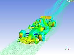
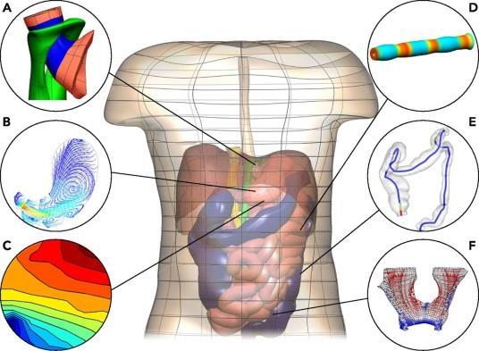
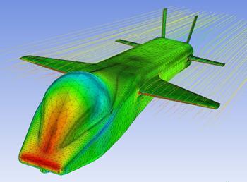
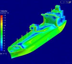
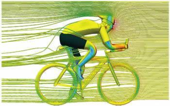
5 CFD Applications HVAC Chemical Processing Hydraulics Automotive Biomedical Aerospace Marine (movie) Sports Oil and Gas Power Generation Hydro Power
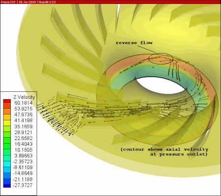
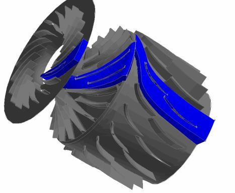
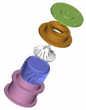
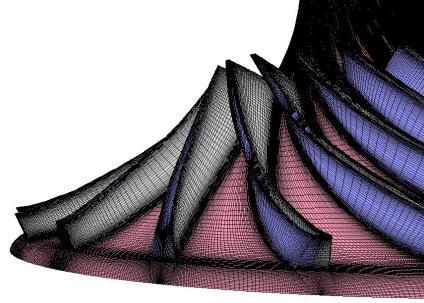
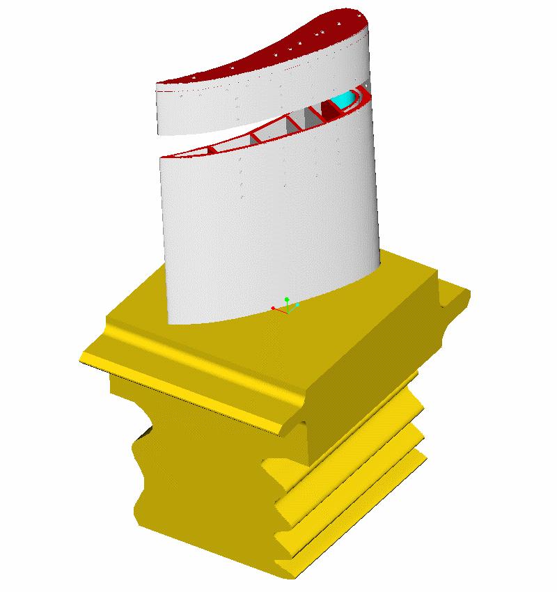

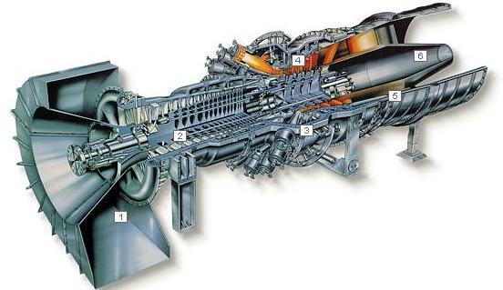

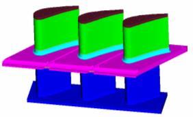
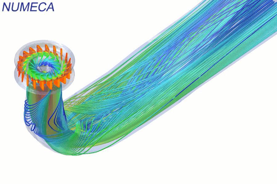
6 CFD Applications in Turbomachinery Tip cap heat transfer Impingement Pin-fin cooling Film cooling holes Internal cooling passages Blade platform IGV Cooling air Source: Dr. Sleiti various projects 6


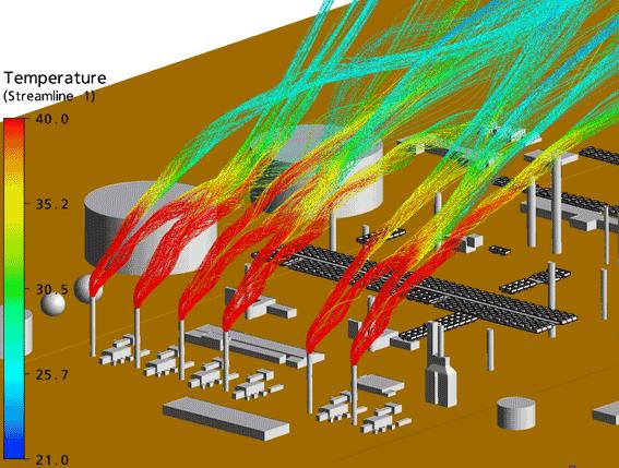
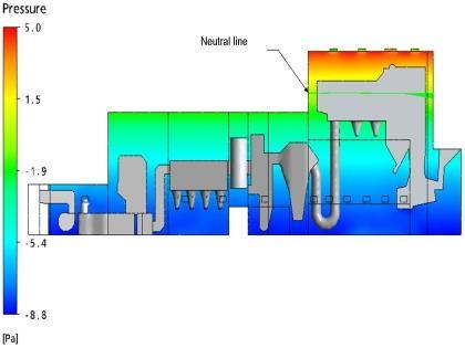
7 CFD Applications in Built Environment Atmospheric modeling Thermal comfort and air quality Smoke and fire propagation Support HVAC design Wind engineering Duct fittings tmcporch.com Source: Dr. Sleiti various projects blogs.rand.com Operation room Heat Exchangers machinedesign.com 7

8 Example Dynamic temperature and flow results, enable engineers to pinpoint thermal and ventilation issues and visualize design improvements quickly and effectively. 8
9 CFD Modeling Modeling is the mathematical physics problem formulation in terms of a continuous initial boundary value problem (IBVP) IBVP is in the form of Partial Differential Equations (PDEs) with appropriate boundary conditions and initial conditions. Modeling includes: o Geometry and domain o Governing equations o Flow conditions o Initial and boundary conditions o Solution model(s) 9

10 Geometry Simple geometries easy to create Complex geometries created using CAD software then imported into commercial CFD code Domain: size and shape Typical approaches Geometry approximation CAD/CAE integration: use of industry standards such as IGES, STEP, etc. 10
11 Governing equations Navier-Stokes equations (3D in Cartesian coordinates) ˆ z w y w x w z p z w w y w v x w u t w ˆ z u y u x u x p z u w y u v x u u t u ˆ z v y v x v y p z v w y v v x v u t v 0 z w y v x u t p RT Convection Pressure gradient Viscous terms Local acceleration Continuity equation Equation of state Energy equation if needed
12 Flow conditions Internal flow or external flow Viscous vs. inviscid Turbulent vs. laminar (Re) Incompressible vs. compressible (Ma) Single- vs. multi-phase Thermal/density effects (Pr, g, Gr, Ec) Combustion and Chemical reactions Other 12
13 Initial conditions Initial conditions (ICs) for transient flows ICs affect convergence To speed up the convergence, reasonable initial guess is needed For complicated unsteady flow problems, CFD codes are usually run in steady mode for a few iterations to get better initial conditions 13
14 Boundary conditions Boundary conditions: o o o No-slip or slip-free on walls, periodic, inlet (velocity inlet, mass flow rate, pressure inlet, etc.), outlet (pressure, velocity, zero-gradient), and non-reflecting (for compressible flows, such as acoustics), etc. Use of Periodic Boundaries to Define Swirling Flow in a Cylindrical Vessel 14
15 Turbulence models DNS: most accurate, but too expensive RANS: predict mean flow structures, efficient inside BL but excessive diffusion in the separated region. LES: accurate in separation region DES: RANS inside BL, LES in separated regions. 15
16 Numerical methods Numerical methods include: 1. Discretization methods 2. Numerical parameters 3. Grid generation 4. Solver 5. Post-processing 16
17 Discretization methods (example) 2D incompressible laminar flow boundary layer 17 0 y v x u 2 2 y u e p x y u v x u u m=0 m=1 L-1 L y x m=mm m=mm+1 (L,m-1) (L,m) (L,m+1) (L-1,m) 1 l l l m m m u u u u u x x 1 l l l m m m v u v u u y y 1 l l l m m m v u u y l l l m m m u u u u y y 2 nd order central difference 1 st order upwind scheme, i.e.
18 Discretization methods (example) B 2 B 3 B 1 1 FD u y 2 v v x 1 BD y y y y y y l l l m l l m l m l vm u 2 m FD u 2 m1 BD u 2 m1 l l l l1 l B1u m1 B2um B3u m1 B4 um p / e m x l1 l um u l1 m x l p l Bu 4 1 B2 B u x e 1 1 B1 B2 B B B B l l B1 B 2 u mm l1 p Bu 4 mm x e mm Matrix has to be Diagonally dominant. B 4 ( p / e ) x l m 18


19 Grid generation Grids can either be structured (hexahedral) or unstructured (tetrahedral) structured Scheme o Finite differences: structured o Finite volume or finite element: structured or unstructured Application o Thin boundary layers best resolved with highly-stretched structured grids o Unstructured grids useful for complex geometries o Unstructured grids permit automatic adaptive refinement based on the pressure gradient, or regions of interest unstructured 19
20 Types of CFD codes Commercial CFD code Research CFD code Public domain software Other CFD software includes the Grid generation software and flow visualization software 20


21 CFD Process: Geometry Determine the domain size and shape Simplifications needed Source: ANSYS - FLUENT 21

22 CFD Process: Mesh Should be well designed to resolve important flow features which are dependent upon flow condition parameters Source: Dr. Sleiti various projects 22

23 CFD Process: Solve Solve the momentum, pressure and other equations and get flow field quantities, such as velocity, turbulence intensity, pressure and integral quantities (lift, drag forces) 23

24 CFD Process: Post-processing Analysis and visualization Calculation of derived variables Vorticity Wall shear stress Calculation of integral parameters: forces, moments Visualization contour plots Vector plots and streamlines Source: Ansys Fluent Animations 24
25 CFD Process: Verification and Validation Simulation error: the difference between a simulation result S and the truth T (objective reality), Verification: process for assessing simulation numerical uncertainties Validation: process for assessing simulation modeling uncertainty by using benchmark experimental data 25
26 Example of CFD Process using FLUENT Turbulent Pipe Flow Problem Specification 1. Pre-Analysis & Start-Up 2. Geometry 3. Mesh 4. Physics Setup 5. Numerical Solution 6. Numerical Results 7. Verification & Validation 26
27 Problem Specification Example of CFD Process Inlet velocity = 1 m/s, The fluid exhausts into the ambient atmosphere density = 1 kg/m 3. µ = 2 x 10⁻⁵ kg/(ms), Reynolds Number = 10,000 Solve for: centerline velocity, skin friction coefficient and the axial velocity profile at the outlet. 27
28 Geometry Example of CFD Process 28

29 Mesh Example of CFD Process 29


30 Physics Setup Example of CFD Process 30


31 Physics Setup Example of CFD Process 31


32 Example of CFD Process Numerical Solution 32
33 Example of CFD Process Numerical Results 33
34 Example of CFD Process Numerical Results 34
35 Numerical Results Example of CFD Process 35
36 Verification and Validation Comparing Meshes: 100 X 60 and 100 X 30 Example of CFD Process 36
37 Verification and Validation Comparing Meshes: 100 X 60 and 100 X 30 Example of CFD Process 37
38 Verification and Validation Comparing Meshes: 100 X 60 and 100 X 30 Example of CFD Process 38
39 Turbulence Modeling Choosing a Turbulence Model No single turbulence model is universally accepted as being superior for all classes of problems. The choice of turbulence model depends on considerations such as flow physics, the established practice for a specific class of problem, accuracy required, computational resources, and time available for the simulation. Reynolds-Averaged Approach vs. LES Two methods can be employed to transform the Navier-Stokes equations in such a way that the small-scale turbulent fluctuations do not have to be directly simulated: Reynolds averaging and filtering. Both methods introduce additional terms in the governing equations that need to be modeled in order to achieve closure". The Reynolds-averaged approach is generally adopted for practical engineering calculations, and uses models such as, k-e, k-w and the RSM. LES provides an alternative approach in which the large eddies are computed in a time-dependent simulation that uses a set of filtered" equations. 39
40 Reynolds Averaging Velocity components: Turbulence Modeling Pressure and other scalar quantities: Reynolds-averaged Navier-Stokes (RANS) equations 40
41 The Standard k-e Model The RNG k-e Model Turbulence Modeling Two-equation model in which the solution of two separate transport equations allows the turbulent velocity and length scales to be independently determined. Robust, economic, and reasonable accuracy for a wide range of turbulent flows High Re model Derived using a rigorous statistical technique (called renormalization group theory). Has an additional term in its e equation that significantly improves the accuracy for rapidly strained flows. The effect of swirl on turbulence is included. Accounts for low-reynolds-number effects. The Realizable k-e Model 41 Contains a new formulation for the turbulent viscosity. A new transport equation for the dissipation rate, e. Accurately predicts the spreading rate of both planar and round jets. Flows involving rotation, boundary layers under strong adverse pressure gradients, separation, and recirculation.
42 The Standard k-w Model Turbulence Modeling The Shear-Stress Transport (SST) k-w Model The Reynolds Stress Model (RSM) 42 Incorporates modifications for low-reynolds-number effects, compressibility, and shear flow spreading. Predicts free shear flow spreading rates for far wakes, mixing layers, and plane, round, and radial jets. Developed to effectively blend the robust and accurate formulation of the k-w model in the near-wall region with the free-stream accurate and reliable for a wider class of flows (e.g., adverse pressure gradient flows, airfoils, transonic shock waves) 4 additional transport equations are required in 2D flows and 7 in 3D. Accounts for the effects of streamline curvature, swirl, rotation, and rapid changes in strain rate limited by the closure assumptions employed to model various terms in the exact transport equations for the Reynolds stresses.
43 Near-Wall Treatments for Wall-Bounded Turbulent Flows The k-e models, the RSM, and the LES model are primarily valid for turbulent core flows (i.e., the flow in the regions somewhat far from walls). Consideration therefore needs to be given as to how to make these models suitable for wallbounded flows. The k-w models were designed to be applied throughout the boundary layer, provided that the near-wall mesh resolution is sufficient. The near-wall region can be subdivided into three layers: Sources: 43
44 Wall Functions vs. Near-Wall Model Sources: 44
45 ASHRAE RP-1682 Study to Identify CFD Models for Use in Determining HVAC Duct Fitting Loss Coefficients Principal Investigators: Ahmad Sleiti, Ph.D., PE Qatar University Stephen Idem, Ph.D. Tennessee Tech University

46 Straight Duct CFD k-e Smooth: 60 x 200 grid Enhanced near wall treatment Results: accurate within 5% for Re < 250,000. For higher Re the error > 10% The reason: Y plus CFD k-e Smooth, Modified Y Plus: The grid points were increased to maintain Y plus less than 25 The error became < 3 % CFD k-e for e/d = rough duct: 60 x 200 grid size and standard wall functions Results: CFD accurate within 7% error for high Re (more than 250,000) and within 12% for low Re (less than 250,000). 46 Figure mm (8.0 in.) Diameter Straight Duct Moody Diagram. Comparison of CFD k-e turbulence model to experimental results Source: work done by Drs Sleiti and Idem
47 Straight Duct CFD RNG k-e for e/d = rough duct: 60 x 200 grid size and standard wall functions Results: error ranges from 6% to more than 17% CFD Realizable k-e for e/d = rough duct: 60 x 200 grid size and standard wall functions Results: error ranges from 10% to more than 21% 47 Figure mm (8.0 in.) Diameter Straight Duct Moody Diagram. Comparison of CFD k- erealizable k-e and RNG k-e turbulence models with wall roughness to experimental results Source: work done by Drs Sleiti and Idem
48 Single Elbow CFD Standard k-e for e/d = rough duct: grid size of 60 x 200 in the entrance region, 60 x 22 in the curve region and 60 x 160 in the exit region and with standard wall functions Results: error ranges from 5% to more than 18% CFD Standard k-w for e/d = rough duct: grid size of 60 x 200 in the entrance region, 60 x 22 in the curve region and 60 x 160 in the exit region and with standard wall functions Results: ranges from 9% to more than 19% 48 Figure mm (8.0 in.) Diameter Single Elbow Loss Coefficient. Comparison of CFD k-e and k-w turbulence models to experimental results Source: work done by Drs Sleiti and Idem
49 Total Pressure Loss (Pa) Double Elbow Loss Coefficient: Z-Configuration CFD Standard k-e for e/d = rough duct: grid size of 60 x 200 in the entrance region, 60 x 22 in the curve regions and 60 x 160 in the exit region and with standard wall functions. Results: error ranges from 0.1% to more than 18% Experimental Data CFD k-w CFD Standard k-w for e/d = rough duct: grid size of 60 x 200 in the entrance region, 60 x 22 in the curve regions and 60 x 160 in the exit region and with standard wall functions. Results: error ranges from 7% to more than 24% Velocity Pressure (Pa) CFD k-e 49 Figure mm (8.0 in.) Diameter Double Elbow Loss Coefficient: Z-Configuration Lint = 2.52 m (8.28 ft). Comparison of CFD k-e and k-w turbulence models to experimental results Source: work done by Drs Sleiti and Idem
 203 mm (8.0 in.")
50 Total Pressure Loss (Pa) U-Configuration Experimental CFD Linear (Experimental) y = 0.352x R² = ANSI/ASHRAE Standard : Figure Velocity Pressure (Pa) 203 mm (8.0 in.) Diameter Double Elbow Loss Coefficient: U-Configuration L int = 2.52 m (8.28 ft) 50


51 CFD - U-Configuration for 12 in diameter - LoD = 10 Results: Static Pressure Contours of static pressure in Pa 51
An Overview of Computational Fluid Dynamics
 An Overview of Computational Fluid Dynamics Dr. Nor Azwadi bin Che Sidik Faculty of Mechanical Engineering Universiti Teknologi Malaysia INSPIRING CREATIVE AND INNOVATIVE MINDS 1 What is CFD? C computational
Verification and Validation of Turbulent Flow around a Clark-Y Airfoil
 Verification and Validation of Turbulent Flow around a Clark-Y Airfoil 1. Purpose 58:160 Intermediate Mechanics of Fluids CFD LAB 2 By Tao Xing and Fred Stern IIHR-Hydroscience & Engineering The University
Chapter 1 Introduction
 Chapter 1 Introduction Ibrahim Sezai Department of Mechanical Engineering Eastern Mediterranean University Fall 2009-2010 What is CFD? CFD is the simulation of fluids engineering systems using modeling
CIBSE Application Manual AM11 Building Performance Modelling Chapter 6: Ventilation Modelling
 Contents Background Ventilation modelling tool categories Simple tools and estimation techniques Analytical methods Zonal network methods Computational Fluid Dynamics (CFD) Semi-external spaces Summary
Introduction to ANSYS CFX
 Workshop 03 Fluid flow around the NACA0012 Airfoil 16.0 Release Introduction to ANSYS CFX 2015 ANSYS, Inc. March 13, 2015 1 Release 16.0 Workshop Description: The flow simulated is an external aerodynamics
Introduction to C omputational F luid Dynamics. D. Murrin
 Introduction to C omputational F luid Dynamics D. Murrin Computational fluid dynamics (CFD) is the science of predicting fluid flow, heat transfer, mass transfer, chemical reactions, and related phenomena
SPC 307 Aerodynamics. Lecture 1. February 10, 2018
 SPC 307 Aerodynamics Lecture 1 February 10, 2018 Sep. 18, 2016 1 Course Materials drahmednagib.com 2 COURSE OUTLINE Introduction to Aerodynamics Review on the Fundamentals of Fluid Mechanics Euler and
Simulation of Turbulent Flow in an Asymmetric Diffuser
 Simulation of Turbulent Flow in an Asymmetric Diffuser 1. Purpose 58:160 Intermediate Mechanics of Fluids CFD LAB 3 By Tao Xing and Fred Stern IIHR-Hydroscience & Engineering The University of Iowa C.
Using a Single Rotating Reference Frame
 Tutorial 9. Using a Single Rotating Reference Frame Introduction This tutorial considers the flow within a 2D, axisymmetric, co-rotating disk cavity system. Understanding the behavior of such flows is
Introduction to Computational Fluid Dynamics Mech 122 D. Fabris, K. Lynch, D. Rich
 Introduction to Computational Fluid Dynamics Mech 122 D. Fabris, K. Lynch, D. Rich 1 Computational Fluid dynamics Computational fluid dynamics (CFD) is the analysis of systems involving fluid flow, heat
Verification of Laminar and Validation of Turbulent Pipe Flows
 1 Verification of Laminar and Validation of Turbulent Pipe Flows 1. Purpose ME:5160 Intermediate Mechanics of Fluids CFD LAB 1 (ANSYS 18.1; Last Updated: Aug. 1, 2017) By Timur Dogan, Michael Conger, Dong-Hwan
Verification and Validation in CFD and Heat Transfer: ANSYS Practice and the New ASME Standard
 Verification and Validation in CFD and Heat Transfer: ANSYS Practice and the New ASME Standard Dimitri P. Tselepidakis & Lewis Collins ASME 2012 Verification and Validation Symposium May 3 rd, 2012 1 Outline
COMPUTATIONAL FLUID DYNAMICS ANALYSIS OF ORIFICE PLATE METERING SITUATIONS UNDER ABNORMAL CONFIGURATIONS
 COMPUTATIONAL FLUID DYNAMICS ANALYSIS OF ORIFICE PLATE METERING SITUATIONS UNDER ABNORMAL CONFIGURATIONS Dr W. Malalasekera Version 3.0 August 2013 1 COMPUTATIONAL FLUID DYNAMICS ANALYSIS OF ORIFICE PLATE
Debojyoti Ghosh. Adviser: Dr. James Baeder Alfred Gessow Rotorcraft Center Department of Aerospace Engineering
 Debojyoti Ghosh Adviser: Dr. James Baeder Alfred Gessow Rotorcraft Center Department of Aerospace Engineering To study the Dynamic Stalling of rotor blade cross-sections Unsteady Aerodynamics: Time varying
ANSYS FLUENT. Airfoil Analysis and Tutorial
 ANSYS FLUENT Airfoil Analysis and Tutorial ENGR083: Fluid Mechanics II Terry Yu 5/11/2017 Abstract The NACA 0012 airfoil was one of the earliest airfoils created. Its mathematically simple shape and age
RANS COMPUTATION OF RIBBED DUCT FLOW USING FLUENT AND COMPARING TO LES
 RANS COMPUTATION OF RIBBED DUCT FLOW USING FLUENT AND COMPARING TO LES Máté M., Lohász +*& / Ákos Csécs + + Department of Fluid Mechanics, Budapest University of Technology and Economics, Budapest * Von
Simulation of Laminar Pipe Flows
 Simulation of Laminar Pipe Flows 57:020 Mechanics of Fluids and Transport Processes CFD PRELAB 1 By Timur Dogan, Michael Conger, Maysam Mousaviraad, Tao Xing and Fred Stern IIHR-Hydroscience & Engineering
Calculate a solution using the pressure-based coupled solver.
 Tutorial 19. Modeling Cavitation Introduction This tutorial examines the pressure-driven cavitating flow of water through a sharpedged orifice. This is a typical configuration in fuel injectors, and brings
NUMERICAL 3D TRANSONIC FLOW SIMULATION OVER A WING
 Review of the Air Force Academy No.3 (35)/2017 NUMERICAL 3D TRANSONIC FLOW SIMULATION OVER A WING Cvetelina VELKOVA Department of Technical Mechanics, Naval Academy Nikola Vaptsarov,Varna, Bulgaria (cvetelina.velkova1985@gmail.com)
Modeling Evaporating Liquid Spray
 Tutorial 17. Modeling Evaporating Liquid Spray Introduction In this tutorial, the air-blast atomizer model in ANSYS FLUENT is used to predict the behavior of an evaporating methanol spray. Initially, the
Simulation of Flow Development in a Pipe
 Tutorial 4. Simulation of Flow Development in a Pipe Introduction The purpose of this tutorial is to illustrate the setup and solution of a 3D turbulent fluid flow in a pipe. The pipe networks are common
Compressible Flow in a Nozzle
 SPC 407 Supersonic & Hypersonic Fluid Dynamics Ansys Fluent Tutorial 1 Compressible Flow in a Nozzle Ahmed M Nagib Elmekawy, PhD, P.E. Problem Specification Consider air flowing at high-speed through a
NUMERICAL INVESTIGATION OF THE FLOW BEHAVIOR INTO THE INLET GUIDE VANE SYSTEM (IGV)
") University of West Bohemia» Department of Power System Engineering NUMERICAL INVESTIGATION OF THE FLOW BEHAVIOR INTO THE INLET GUIDE VANE SYSTEM (IGV) Publication was supported by project: Budování excelentního
University of West Bohemia» Department of Power System Engineering NUMERICAL INVESTIGATION OF THE FLOW BEHAVIOR INTO THE INLET GUIDE VANE SYSTEM (IGV) Publication was supported by project: Budování excelentního
Non-Newtonian Transitional Flow in an Eccentric Annulus
 Tutorial 8. Non-Newtonian Transitional Flow in an Eccentric Annulus Introduction The purpose of this tutorial is to illustrate the setup and solution of a 3D, turbulent flow of a non-newtonian fluid. Turbulent
Flow and Heat Transfer in a Mixing Elbow
 Flow and Heat Transfer in a Mixing Elbow Objectives The main objectives of the project are to learn (i) how to set up and perform flow simulations with heat transfer and mixing, (ii) post-processing and
Use of CFD in Design and Development of R404A Reciprocating Compressor
 Purdue University Purdue e-pubs International Compressor Engineering Conference School of Mechanical Engineering 2006 Use of CFD in Design and Development of R404A Reciprocating Compressor Yogesh V. Birari
McNair Scholars Research Journal
 McNair Scholars Research Journal Volume 2 Article 1 2015 Benchmarking of Computational Models against Experimental Data for Velocity Profile Effects on CFD Analysis of Adiabatic Film-Cooling Effectiveness
ON THE NUMERICAL MODELING OF IMPINGING JET HEAT TRANSFER
 ON THE NUMERICAL MODELING OF IMPINGING JET HEAT TRANSFER Mirko Bovo 1,2, Sassan Etemad 2 and Lars Davidson 1 1 Dept. of Applied Mechanics, Chalmers University of Technology, Gothenburg, Sweden 2 Powertrain
Axisymmetric Viscous Flow Modeling for Meridional Flow Calculation in Aerodynamic Design of Half-Ducted Blade Rows
 Memoirs of the Faculty of Engineering, Kyushu University, Vol.67, No.4, December 2007 Axisymmetric Viscous Flow Modeling for Meridional Flow alculation in Aerodynamic Design of Half-Ducted Blade Rows by
Simulation and Validation of Turbulent Pipe Flows
 Simulation and Validation of Turbulent Pipe Flows ENGR:2510 Mechanics of Fluids and Transport Processes CFD LAB 1 (ANSYS 17.1; Last Updated: Oct. 10, 2016) By Timur Dogan, Michael Conger, Dong-Hwan Kim,
1. What, why and where of CFD? 2. Modeling 3. Numerical methods
 Introduction ti to Computational ti Fluid Dynamics (CFD) Tao Xing and Fred Stern Outline 1. What, why and where of CFD?. Modeling 3. Numerical methods 4. Types of CFD codes 5. CFD Educational Interface
The Spalart Allmaras turbulence model
 The Spalart Allmaras turbulence model The main equation The Spallart Allmaras turbulence model is a one equation model designed especially for aerospace applications; it solves a modelled transport equation
High-Lift Aerodynamics: STAR-CCM+ Applied to AIAA HiLiftWS1 D. Snyder
 High-Lift Aerodynamics: STAR-CCM+ Applied to AIAA HiLiftWS1 D. Snyder Aerospace Application Areas Aerodynamics Subsonic through Hypersonic Aeroacoustics Store release & weapons bay analysis High lift devices
NUMERICAL SIMULATION OF FLOW FIELD IN AN ANNULAR TURBINE STATOR WITH FILM COOLING
 24 TH INTERNATIONAL CONGRESS OF THE AERONAUTICAL SCIENCES NUMERICAL SIMULATION OF FLOW FIELD IN AN ANNULAR TURBINE STATOR WITH FILM COOLING Jun Zeng *, Bin Wang *, Yong Kang ** * China Gas Turbine Establishment,
Driven Cavity Example
 BMAppendixI.qxd 11/14/12 6:55 PM Page I-1 I CFD Driven Cavity Example I.1 Problem One of the classic benchmarks in CFD is the driven cavity problem. Consider steady, incompressible, viscous flow in a square
CFD Best Practice Guidelines: A process to understand CFD results and establish Simulation versus Reality
 CFD Best Practice Guidelines: A process to understand CFD results and establish Simulation versus Reality Judd Kaiser ANSYS Inc. judd.kaiser@ansys.com 2005 ANSYS, Inc. 1 ANSYS, Inc. Proprietary Overview
MOMENTUM AND HEAT TRANSPORT INSIDE AND AROUND
 MOMENTUM AND HEAT TRANSPORT INSIDE AND AROUND A CYLINDRICAL CAVITY IN CROSS FLOW G. LYDON 1 & H. STAPOUNTZIS 2 1 Informatics Research Unit for Sustainable Engrg., Dept. of Civil Engrg., Univ. College Cork,
CFD Analysis of a Fully Developed Turbulent Flow in a Pipe with a Constriction and an Obstacle
 CFD Analysis of a Fully Developed Turbulent Flow in a Pipe with a Constriction and an Obstacle C, Diyoke Mechanical Engineering Department Enugu State University of Science & Tech. Enugu, Nigeria U, Ngwaka
Computation of Velocity, Pressure and Temperature Distributions near a Stagnation Point in Planar Laminar Viscous Incompressible Flow
 Excerpt from the Proceedings of the COMSOL Conference 8 Boston Computation of Velocity, Pressure and Temperature Distributions near a Stagnation Point in Planar Laminar Viscous Incompressible Flow E. Kaufman
Simulation of Turbulent Flow around an Airfoil
 1. Purpose Simulation of Turbulent Flow around an Airfoil ENGR:2510 Mechanics of Fluids and Transfer Processes CFD Lab 2 (ANSYS 17.1; Last Updated: Nov. 7, 2016) By Timur Dogan, Michael Conger, Andrew
Simulation of Turbulent Flow over the Ahmed Body
 Simulation of Turbulent Flow over the Ahmed Body 58:160 Intermediate Mechanics of Fluids CFD LAB 4 By Timur K. Dogan, Michael Conger, Maysam Mousaviraad, and Fred Stern IIHR-Hydroscience & Engineering
Application of Wray-Agarwal Turbulence Model for Accurate Numerical Simulation of Flow Past a Three-Dimensional Wing-body
 Washington University in St. Louis Washington University Open Scholarship Mechanical Engineering and Materials Science Independent Study Mechanical Engineering & Materials Science 4-28-2016 Application
Modeling Evaporating Liquid Spray
 Tutorial 16. Modeling Evaporating Liquid Spray Introduction In this tutorial, FLUENT s air-blast atomizer model is used to predict the behavior of an evaporating methanol spray. Initially, the air flow
Tutorial 1. Introduction to Using FLUENT: Fluid Flow and Heat Transfer in a Mixing Elbow
 Tutorial 1. Introduction to Using FLUENT: Fluid Flow and Heat Transfer in a Mixing Elbow Introduction This tutorial illustrates the setup and solution of the two-dimensional turbulent fluid flow and heat
Estimating Vertical Drag on Helicopter Fuselage during Hovering
 Estimating Vertical Drag on Helicopter Fuselage during Hovering A. A. Wahab * and M.Hafiz Ismail ** Aeronautical & Automotive Dept., Faculty of Mechanical Engineering, Universiti Teknologi Malaysia, 81310
Express Introductory Training in ANSYS Fluent Workshop 04 Fluid Flow Around the NACA0012 Airfoil
 Express Introductory Training in ANSYS Fluent Workshop 04 Fluid Flow Around the NACA0012 Airfoil Dimitrios Sofialidis Technical Manager, SimTec Ltd. Mechanical Engineer, PhD PRACE Autumn School 2013 -
Three Dimensional Numerical Simulation of Turbulent Flow Over Spillways
 Three Dimensional Numerical Simulation of Turbulent Flow Over Spillways Latif Bouhadji ASL-AQFlow Inc., Sidney, British Columbia, Canada Email: lbouhadji@aslenv.com ABSTRACT Turbulent flows over a spillway
The study of air distribution in tunnels and large industrial buildings
 Ventilation, Airflow and Contaminant Transport in Buildings The study of air distribution in tunnels and large industrial buildings 13th January 2017 7. Semester Project Indoor Environmental & Energy Engineering
Analysis of an airfoil
 UNDERGRADUATE RESEARCH FALL 2010 Analysis of an airfoil using Computational Fluid Dynamics Tanveer Chandok 12/17/2010 Independent research thesis at the Georgia Institute of Technology under the supervision
Turbulence Modeling. Gilles Eggenspieler, Ph.D. Senior Product Manager
 Turbulence Modeling Gilles Eggenspieler, Ph.D. Senior Product Manager 1 Overview The Role of Steady State (RANS) Turbulence Modeling Overview of Reynolds-Averaged Navier Stokes (RANS) Modeling Capabilities
Ashwin Shridhar et al. Int. Journal of Engineering Research and Applications ISSN : , Vol. 5, Issue 6, ( Part - 5) June 2015, pp.
 June 2015, pp.") RESEARCH ARTICLE OPEN ACCESS Conjugate Heat transfer Analysis of helical fins with airfoil crosssection and its comparison with existing circular fin design for air cooled engines employing constant rectangular
RESEARCH ARTICLE OPEN ACCESS Conjugate Heat transfer Analysis of helical fins with airfoil crosssection and its comparison with existing circular fin design for air cooled engines employing constant rectangular
Modeling External Compressible Flow
 Tutorial 3. Modeling External Compressible Flow Introduction The purpose of this tutorial is to compute the turbulent flow past a transonic airfoil at a nonzero angle of attack. You will use the Spalart-Allmaras
CFD Modeling of a Radiator Axial Fan for Air Flow Distribution
 CFD Modeling of a Radiator Axial Fan for Air Flow Distribution S. Jain, and Y. Deshpande Abstract The fluid mechanics principle is used extensively in designing axial flow fans and their associated equipment.
Introduction to CFX. Workshop 2. Transonic Flow Over a NACA 0012 Airfoil. WS2-1. ANSYS, Inc. Proprietary 2009 ANSYS, Inc. All rights reserved.
 Workshop 2 Transonic Flow Over a NACA 0012 Airfoil. Introduction to CFX WS2-1 Goals The purpose of this tutorial is to introduce the user to modelling flow in high speed external aerodynamic applications.
in:flux - Intelligent CFD Software
 in:flux - Intelligent CFD Software info@insightnumerics.com Fire and Gas Mapping. Optimized. Slide 1 Introduction to in:flux in:flux is a CFD software product to be used for dispersion and ventilation
Development of Hybrid Fluid Jet / Float Polishing Process
 COMSOL Conference - Tokyo 2013 Development of Hybrid Fluid Jet / Float Polishing Process A. Beaucamp, Y. Namba Dept. of Mechanical Engineering, Chubu University, Japan Zeeko LTD, United Kingdom Research
CFD Analysis of 2-D Unsteady Flow Past a Square Cylinder at an Angle of Incidence
 CFD Analysis of 2-D Unsteady Flow Past a Square Cylinder at an Angle of Incidence Kavya H.P, Banjara Kotresha 2, Kishan Naik 3 Dept. of Studies in Mechanical Engineering, University BDT College of Engineering,
Numerical Study of Turbulent Flow over Backward-Facing Step with Different Turbulence Models
 Numerical Study of Turbulent Flow over Backward-Facing Step with Different Turbulence Models D. G. Jehad *,a, G. A. Hashim b, A. K. Zarzoor c and C. S. Nor Azwadi d Department of Thermo-Fluids, Faculty
Using Multiple Rotating Reference Frames
 Tutorial 10. Using Multiple Rotating Reference Frames Introduction Many engineering problems involve rotating flow domains. One example is the centrifugal blower unit that is typically used in automotive
Simulation of Turbulent Axisymmetric Waterjet Using Computational Fluid Dynamics (CFD)
") Simulation of Turbulent Axisymmetric Waterjet Using Computational Fluid Dynamics (CFD) PhD. Eng. Nicolae MEDAN 1 1 Technical University Cluj-Napoca, North University Center Baia Mare, Nicolae.Medan@cunbm.utcluj.ro
Simulation of Turbulent Axisymmetric Waterjet Using Computational Fluid Dynamics (CFD) PhD. Eng. Nicolae MEDAN 1 1 Technical University Cluj-Napoca, North University Center Baia Mare, Nicolae.Medan@cunbm.utcluj.ro
Analysis of a curvature corrected turbulence model using a 90 degree curved geometry modelled after a centrifugal compressor impeller
 Analysis of a curvature corrected turbulence model using a 90 degree curved geometry modelled after a centrifugal compressor impeller K. J. Elliott 1, E. Savory 1, C. Zhang 1, R. J. Martinuzzi 2 and W.
Coupled Analysis of FSI
 Coupled Analysis of FSI Qin Yin Fan Oct. 11, 2008 Important Key Words Fluid Structure Interface = FSI Computational Fluid Dynamics = CFD Pressure Displacement Analysis = PDA Thermal Stress Analysis = TSA
Transition Flow and Aeroacoustic Analysis of NACA0018 Satish Kumar B, Fred Mendonç a, Ghuiyeon Kim, Hogeon Kim
 Transition Flow and Aeroacoustic Analysis of NACA0018 Satish Kumar B, Fred Mendonç a, Ghuiyeon Kim, Hogeon Kim Transition Flow and Aeroacoustic Analysis of NACA0018 Satish Kumar B, Fred Mendonç a, Ghuiyeon
Comparison Between Numerical & PIV Experimental Results for Gas-Solid Flow in Ducts
 Fabio Kasper Comparison Between Numerical & PIV Experimental Results for Gas-Solid Flow in Ducts Rodrigo Decker, Oscar Sgrott Jr., Henry F. Meier Waldir Martignoni Agenda Introduction The Test Bench Case
This tutorial illustrates how to set up and solve a problem involving solidification. This tutorial will demonstrate how to do the following:
 Tutorial 22. Modeling Solidification Introduction This tutorial illustrates how to set up and solve a problem involving solidification. This tutorial will demonstrate how to do the following: Define a
Turbulencja w mikrokanale i jej wpływ na proces emulsyfikacji
 Polish Academy of Sciences Institute of Fundamental Technological Research Turbulencja w mikrokanale i jej wpływ na proces emulsyfikacji S. Błoński, P.Korczyk, T.A. Kowalewski PRESENTATION OUTLINE 0 Introduction
SIMULATION OF PROPELLER-SHIP HULL INTERACTION USING AN INTEGRATED VLM/RANSE SOLVER MODELING.
 SIMULATION OF PROPELLER-SHIP HULL INTERACTION USING AN INTEGRATED VLM/RANSE SOLVER MODELING. M.N.Senthil Prakash, Department of Ocean Engineering, IIT Madras, India V. Anantha Subramanian Department of
Modeling Flow Through Porous Media
 Tutorial 7. Modeling Flow Through Porous Media Introduction Many industrial applications involve the modeling of flow through porous media, such as filters, catalyst beds, and packing. This tutorial illustrates
Backward facing step Homework. Department of Fluid Mechanics. For Personal Use. Budapest University of Technology and Economics. Budapest, 2010 autumn
 Backward facing step Homework Department of Fluid Mechanics Budapest University of Technology and Economics Budapest, 2010 autumn Updated: October 26, 2010 CONTENTS i Contents 1 Introduction 1 2 The problem
Shape optimisation using breakthrough technologies
 Shape optimisation using breakthrough technologies Compiled by Mike Slack Ansys Technical Services 2010 ANSYS, Inc. All rights reserved. 1 ANSYS, Inc. Proprietary Introduction Shape optimisation technologies
Investigation of cross flow over a circular cylinder at low Re using the Immersed Boundary Method (IBM)
") Computational Methods and Experimental Measurements XVII 235 Investigation of cross flow over a circular cylinder at low Re using the Immersed Boundary Method (IBM) K. Rehman Department of Mechanical Engineering,
Computational Methods and Experimental Measurements XVII 235 Investigation of cross flow over a circular cylinder at low Re using the Immersed Boundary Method (IBM) K. Rehman Department of Mechanical Engineering,
NUMERICAL SIMULATIONS OF FLOW THROUGH AN S-DUCT
 NUMERICAL SIMULATIONS OF FLOW THROUGH AN S-DUCT 1 Pravin Peddiraju, 1 Arthur Papadopoulos, 2 Vangelis Skaperdas, 3 Linda Hedges 1 BETA CAE Systems USA, Inc., USA, 2 BETA CAE Systems SA, Greece, 3 CFD Consultant,
real world design & problems fluid flow engineering solving Computational Fluid Dynamics System
 C F D 2 0 0 0 Computational Fluid Dynamics System solving real world engineering design & problems aerospace architecture automotive biomedical chemical processing electrical cooling environmental marine
Numerical and theoretical analysis of shock waves interaction and reflection
 Fluid Structure Interaction and Moving Boundary Problems IV 299 Numerical and theoretical analysis of shock waves interaction and reflection K. Alhussan Space Research Institute, King Abdulaziz City for
Speed and Accuracy of CFD: Achieving Both Successfully ANSYS UK S.A.Silvester
 Speed and Accuracy of CFD: Achieving Both Successfully ANSYS UK S.A.Silvester 2010 ANSYS, Inc. All rights reserved. 1 ANSYS, Inc. Proprietary Content ANSYS CFD Introduction ANSYS, the company Simulation
Introduction To FLUENT. David H. Porter Minnesota Supercomputer Institute University of Minnesota
 Introduction To FLUENT David H. Porter Minnesota Supercomputer Institute University of Minnesota Topics Covered in this Tutorial What you can do with FLUENT FLUENT is feature rich Summary of features and
Computational Study of Laminar Flowfield around a Square Cylinder using Ansys Fluent
 MEGR 7090-003, Computational Fluid Dynamics :1 7 Spring 2015 Computational Study of Laminar Flowfield around a Square Cylinder using Ansys Fluent Rahul R Upadhyay Master of Science, Dept of Mechanical
ITTC Recommended Procedures and Guidelines
 Page 1 of 9 Table of Contents 1. OVERVIEW... 2 2. CHOICE OF MODEL OR FULL SCALE... 2 3. NOMINAL WAKE IN MODEL SCALE... 3 3.1 Pre-processing... 3 3.1.1 Geometry... 3 3.1.2 Computational Domain and Boundary
CFD Modelling in the Cement Industry
 CFD Modelling in the Cement Industry Victor J. Turnell, P.E., Turnell Corp., USA, describes computational fluid dynamics (CFD) simulation and its benefits in applications in the cement industry. Introduction
Flow in an Intake Manifold
 Tutorial 2. Flow in an Intake Manifold Introduction The purpose of this tutorial is to model turbulent flow in a simple intake manifold geometry. An intake manifold is a system of passages which carry
The viscous forces on the cylinder are proportional to the gradient of the velocity field at the
 Fluid Dynamics Models : Flow Past a Cylinder Flow Past a Cylinder Introduction The flow of fluid behind a blunt body such as an automobile is difficult to compute due to the unsteady flows. The wake behind
Program: Advanced Certificate Program
 Program: Advanced Certificate Program Course: CFD-Vehicle Aerodynamics Directorate of Training and Lifelong Learning #470-P, Peenya Industrial Area, 4th Phase Peenya, Bengaluru 560 058 www.msruas.ac.in
Using Multiple Rotating Reference Frames
 Tutorial 9. Using Multiple Rotating Reference Frames Introduction Many engineering problems involve rotating flow domains. One example is the centrifugal blower unit that is typically used in automotive
CFD MODELING FOR PNEUMATIC CONVEYING
 CFD MODELING FOR PNEUMATIC CONVEYING Arvind Kumar 1, D.R. Kaushal 2, Navneet Kumar 3 1 Associate Professor YMCAUST, Faridabad 2 Associate Professor, IIT, Delhi 3 Research Scholar IIT, Delhi e-mail: arvindeem@yahoo.co.in
Modeling Unsteady Compressible Flow
 Tutorial 4. Modeling Unsteady Compressible Flow Introduction In this tutorial, FLUENT s density-based implicit solver is used to predict the timedependent flow through a two-dimensional nozzle. As an initial
1.2 Numerical Solutions of Flow Problems
 1.2 Numerical Solutions of Flow Problems DIFFERENTIAL EQUATIONS OF MOTION FOR A SIMPLIFIED FLOW PROBLEM Continuity equation for incompressible flow: 0 Momentum (Navier-Stokes) equations for a Newtonian
CFD-1. Introduction: What is CFD? T. J. Craft. Msc CFD-1. CFD: Computational Fluid Dynamics
 School of Mechanical Aerospace and Civil Engineering CFD-1 T. J. Craft George Begg Building, C41 Msc CFD-1 Reading: J. Ferziger, M. Peric, Computational Methods for Fluid Dynamics H.K. Versteeg, W. Malalasekara,
S-ducts and Nozzles: STAR-CCM+ at the Propulsion Aerodynamics Workshop. Peter Burns, CD-adapco
 S-ducts and Nozzles: STAR-CCM+ at the Propulsion Aerodynamics Workshop Peter Burns, CD-adapco Background The Propulsion Aerodynamics Workshop (PAW) has been held twice PAW01: 2012 at the 48 th AIAA JPC
WALL Y + APPROACH FOR DEALING WITH TURBULENT FLOW OVER A SURFACE MOUNTED CUBE: PART 2 HIGH REYNOLDS NUMBER
 Seventh International Conference on CFD in the Minerals and Process Industries CSIRO, Melbourne, Australia 9- December 9 WALL Y + APPROACH FOR DEALING WITH TURBULENT FLOW OVER A SURFACE MOUNTED CUBE: PART
Modeling Supersonic Jet Screech Noise Using Direct Computational Aeroacoustics (CAA) 14.5 Release
 14.5 Release") Modeling Supersonic Jet Screech Noise Using Direct Computational Aeroacoustics (CAA) 14.5 Release 2011 ANSYS, Inc. November 7, 2012 1 Workshop Advanced ANSYS FLUENT Acoustics Introduction This tutorial
Modeling Supersonic Jet Screech Noise Using Direct Computational Aeroacoustics (CAA) 14.5 Release 2011 ANSYS, Inc. November 7, 2012 1 Workshop Advanced ANSYS FLUENT Acoustics Introduction This tutorial
CAD-BASED WORKFLOWS. VSP Workshop 2017
 CAD-BASED WORKFLOWS VSP Workshop 2017 RESEARCH IN FLIGHT COMPANY Established 2012 Primary functions are the development, marketing and support of FlightStream and the development of aerodynamic solutions
Simulation of Turbulent Flow around an Airfoil
 Simulation of Turbulent Flow around an Airfoil ENGR:2510 Mechanics of Fluids and Transfer Processes CFD Pre-Lab 2 (ANSYS 17.1; Last Updated: Nov. 7, 2016) By Timur Dogan, Michael Conger, Andrew Opyd, Dong-Hwan
Computational Fluid Dynamics modeling of a Water Flow Over an Ogee Profile
 FINITE ELEMENT METHOD TECHNICAL REPORT Computational Fluid Dynamics modeling of a Water Flow Over an Ogee Profile ANSYS CFX 12 ENME 547 Dr. Sudak Matias Sessarego Written Report Due Date: Friday December
Optimizing Bio-Inspired Flow Channel Design on Bipolar Plates of PEM Fuel Cells
 Excerpt from the Proceedings of the COMSOL Conference 2010 Boston Optimizing Bio-Inspired Flow Channel Design on Bipolar Plates of PEM Fuel Cells James A. Peitzmeier *1, Steven Kapturowski 2 and Xia Wang
DES Turbulence Modeling for ICE Flow Simulation in OpenFOAM
 2 nd Two-day Meeting on ICE Simulations Using OpenFOAM DES Turbulence Modeling for ICE Flow Simulation in OpenFOAM V. K. Krastev 1, G. Bella 2 and G. Campitelli 1 University of Tuscia, DEIM School of Engineering
Fluent User Services Center
 Solver Settings 5-1 Using the Solver Setting Solver Parameters Convergence Definition Monitoring Stability Accelerating Convergence Accuracy Grid Independence Adaption Appendix: Background Finite Volume
Module D: Laminar Flow over a Flat Plate
 Module D: Laminar Flow over a Flat Plate Summary... Problem Statement Geometry and Mesh Creation Problem Setup Solution. Results Validation......... Mesh Refinement.. Summary This ANSYS FLUENT tutorial
CFD Simulation for Stratified Oil-Water Two-Phase Flow in a Horizontal Pipe
 CFD Simulation for Stratified Oil-Water Two-Phase Flow in a Horizontal Pipe Adib Zulhilmi Mohd Alias, a, Jaswar Koto, a,b,* and Yasser Mohamed Ahmed, a a) Department of Aeronautics, Automotive and Ocean
Comparison of CFD Simulation of a Hyundai I20 Model with Four Different Turbulence Models
 RESEARCH ARTICLE OPEN ACCESS Comparison of CFD Simulation of a Hyundai I20 with Four Different Turbulence s M. Vivekanandan*, R. Sivakumar**, Aashis. S. Roy*** *(Uttam Industrial Engg. Pvt. Ltd., Tiruchirapalli,
Accurate and Efficient Turbomachinery Simulation. Chad Custer, PhD Turbomachinery Technical Specialist
 Accurate and Efficient Turbomachinery Simulation Chad Custer, PhD Turbomachinery Technical Specialist Outline Turbomachinery simulation advantages Axial fan optimization Description of design objectives