Geometric Field Tracing through an Off- Axis Parabolic Mirror
|
|
|
- Eric Lang
- 6 years ago
- Views:
Transcription
1 UseCase.0077 (1.0) Geometric Field Tracing through an Off- Axis Parabolic Mirror Keywords: focus, geometric field tracing, diffractive field tracing
2 Description This use case explains the usage of the Geometric Field Tracing Plus engine and shows how to get access to the electromagnetic field information of the propagated field in a detector plane. The Geometric Field Tracing engine is used to calculate the field in short distance before the focus. The result of the Geometric Field Tracing engine is converted into a harmonic field. The harmonic field is propagated by a diffractive propagation (rigorous SPW operator) step into the focus.
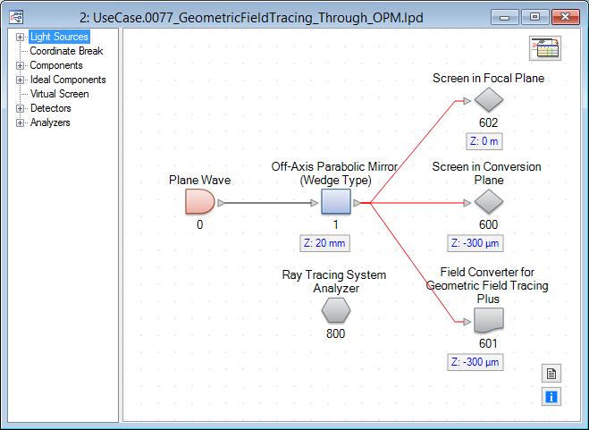
3 The System Filename: UseCase.0077_GeometricFieldTracing_Through_OPM.lpd
4 System Configuration The system contains a plane wave light source which has a diameter of 12mm x 12mm. The light source is monochromatic and has a defined wavelength of 532nm. The off-axis parabolic mirror is placed 20mm after the source. The mirror works in 90 deflection angle, has a focal length of 20mm and a diameter of 20mm x 20mm. Within the edit dialog of the mirror a special reference point (in the focal point) for positioning on the reflection channel is selected.
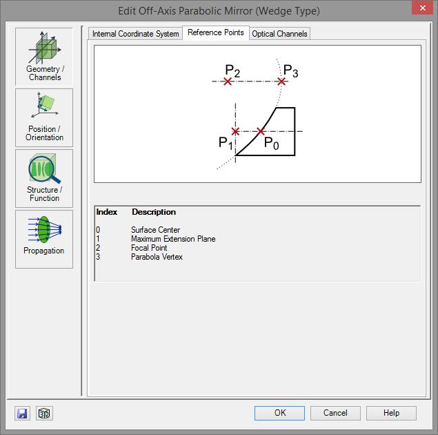
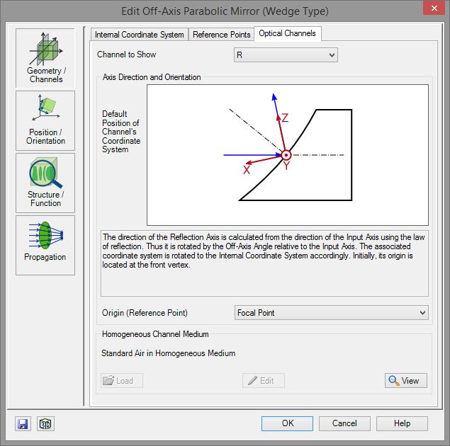
5 Geometry/Channel of the Mirror
6 System Configuration By this positioning specification the detectors are now positioned relatively to the focal plane. Within the optical setup we use three detectors: Virtual Screen (in focal plane) Virtual Screen (300µm before the focal plane conversion plane) Field Converter for Geometric Field Tracing Plus (300µm before the focal plane conversion plane) The converter is part of the User Experience Program. It is not yet available as integrated component. The combination of geometrical and diffractive field tracing techniques will be automatized soon. This is part of the User Experience Program.

7 Edit Options of the Converter On the left side the edit dialog of the field converter is shown. The user can enter Field Size Sampling Distance These parameters will be used for conversion. These functions will be automated soon.

8 Simulation Result Ray Tracing System Analyzer

9 Simulation Result Ray Tracing System Analyzer Focal Plane Conversion Plane

10 Result of Ray Tracing Engine Result in Conversion Plane Result in Focal Plane


11 Results of Geometric Field Tracing Plus Result in Conversion Plane Converted Harmonic Field

12 Propagation into the Focal Plane The converted field information can now be propagated into the focal plane using a diffractive propagation operator. The propagation operator can be selected on the Propagation ribbon. In this case we use the Automatic Propagation Operator.
 In our case the automatic propagation operator will select the rigorous")
13 Specification of the Propagation Operator For the diffractive propagation step we enter a distance of 300µm. (This was the difference between the conversion and the focal plane) In our case the automatic propagation operator will select the rigorous Spectrum of Plane Waves operator.

")
14 Result within the Focal Plane Field in Focal Plane Field in Focal Plane (Zoomed)


15 Result within the Focal Plane Field in Focal Plane (Ex) Field in Focal Plane (Ez)
16 Summary VirtualLab Fusion allows the usage of the Geometric Field Tracing engine. With this engine you can investigate electromagnetic field information within your system as fast as smart ray tracing can deliver the information. The conversion into harmonic fields (sets) allow a further propagation by diffractive propagation techniques. This enables the evaluation of the field in the focus of (for example) an off-axis parabolic mirror. Currently the combination between geometric and diffractive field tracing techniques has to be done manually. This will be improved soon.
Building the Future of Optical Modeling and Design
 SIOM, Lecture Series Building the Future of Optical Modeling and Design Frank Wyrowski Friedrich-Schiller-University, Professor LightTrans GmbH, President Jena, Germany frank.wyrowski@uni-jena.de Lecture
Specification of Diffraction Orders for Grating Regions
 Specification of Diffraction Orders for Grating Regions Abstract For the configuration of waveguide layouts VirtualLab offers the waveguide component. Within this component it is possible to define an
Advanced modelling of gratings in VirtualLab software. Site Zhang, development engineer Lignt Trans
 Advanced modelling of gratings in VirtualLab software Site Zhang, development engineer Lignt Trans 1 2 3 4 Content Grating Order Analyzer Rigorous Simulation of Holographic Generated Volume Grating Coupled
Configuration of Light Sources
 UseCase.0012 (1.0) Configuration of Light Sources Keywords: LED, laser, harmonic fields, harmonic fields set, spectra, pulses, polarization Description This use case explains how light sources are configured
Supplementary Figure 1 Optimum transmissive mask design for shaping an incident light to a desired
 Supplementary Figure 1 Optimum transmissive mask design for shaping an incident light to a desired tangential form. (a) The light from the sources and scatterers in the half space (1) passes through the
Usage of the Parameter Run Document
 UseCase.0065 (1.0) Usage of the Parameter Run Document Keywords: parameter, varying, variation, change, tolerance, simulation, parallelization, combination, random, Monte Carlo, result animation Parameter
Settings and Result Displays of the Ray Tracing Engine
 UseCase.0047 (1.0) Settings and Result Displays of the Ray Tracing Engine Keywords: Ray tracing, dot diagram, position, direction, optical path length, absorption, triangle option, ray selection Description
PROCEEDINGS OF SPIE. Simulation of lateral color for a hybrid refractive-diffractive eyepiece by field tracing methods
 PROCEEDINGS OF SPIE SPIEDigitalLibrary.org/conference-proceedings-of-spie Simulation of lateral color for a hybrid refractive-diffractive eyepiece by field tracing methods D. Batte, M. Kuhn, F. Wyrowski
Positioning & Orientation of Elements
 UseCase.0011 (1.0) Positioning & Orientation of Elements Keywords: positioning, orientation, element, component, angle, basal, isolated, input channel, output channel, coordinate system, origin, separate,
Let s review the four equations we now call Maxwell s equations. (Gauss s law for magnetism) (Faraday s law)
 (Faraday s law)") Electromagnetic Waves Let s review the four equations we now call Maxwell s equations. E da= B d A= Q encl ε E B d l = ( ic + ε ) encl (Gauss s law) (Gauss s law for magnetism) dφ µ (Ampere s law) dt dφ
Electromagnetic Waves Let s review the four equations we now call Maxwell s equations. E da= B d A= Q encl ε E B d l = ( ic + ε ) encl (Gauss s law) (Gauss s law for magnetism) dφ µ (Ampere s law) dt dφ
LIGHT. Speed of light Law of Reflection Refraction Snell s Law Mirrors Lenses
 LIGHT Speed of light Law of Reflection Refraction Snell s Law Mirrors Lenses Light = Electromagnetic Wave Requires No Medium to Travel Oscillating Electric and Magnetic Field Travel at the speed of light
Chapter 36. Image Formation
 Chapter 36 Image Formation Apr 22, 2012 Light from distant things We learn about a distant thing from the light it generates or redirects. The lenses in our eyes create images of objects our brains can
Light. Electromagnetic wave with wave-like nature Refraction Interference Diffraction
 Light Electromagnetic wave with wave-like nature Refraction Interference Diffraction Light Electromagnetic wave with wave-like nature Refraction Interference Diffraction Photons with particle-like nature
Basic optics. Geometrical optics and images Interference Diffraction Diffraction integral. we use simple models that say a lot! more rigorous approach
 Basic optics Geometrical optics and images Interference Diffraction Diffraction integral we use simple models that say a lot! more rigorous approach Basic optics Geometrical optics and images Interference
Reflection AB5 Concave Mirror. Teacher s Notes
 Reflection: Concave Mirror Teacher s Notes Main Topic Subtopic Learning Level Technology Level Activity Type Required Equipment Optional Equipment & Color Reflection Middle Low Student and Optical Set
Lecture 16: Geometrical Optics. Reflection Refraction Critical angle Total internal reflection. Polarisation of light waves
 Lecture 6: Geometrical Optics Reflection Refraction Critical angle Total internal reflection Polarisation of light waves Geometrical Optics Optics Branch of Physics, concerning the interaction of light
Lenses lens equation (for a thin lens) = (η η ) f r 1 r 2
 = (η η ) f r 1 r 2") Lenses lens equation (for a thin lens) 1 1 1 ---- = (η η ) ------ - ------ f r 1 r 2 Where object o f = focal length η = refractive index of lens material η = refractive index of adjacent material r 1
Lenses lens equation (for a thin lens) 1 1 1 ---- = (η η ) ------ - ------ f r 1 r 2 Where object o f = focal length η = refractive index of lens material η = refractive index of adjacent material r 1
Ray optics! Postulates Optical components GRIN optics Matrix optics
 Ray optics! Postulates Optical components GRIN optics Matrix optics Ray optics! 1. Postulates of ray optics! 2. Simple optical components! 3. Graded index optics! 4. Matrix optics!! From ray optics to
Fresnel's biprism and mirrors
 Fresnel's biprism and mirrors 1 Table of Contents Section Page Back ground... 3 Basic Experiments Experiment 1: Fresnel's mirrors... 4 Experiment 2: Fresnel's biprism... 7 2 Back ground Interference of
Geometrical Optics INTRODUCTION. Wave Fronts and Rays
 Geometrical Optics INTRODUCTION In this experiment, the optical characteristics of mirrors, lenses, and prisms will be studied based on using the following physics definitions and relationships plus simple
Geometric Optics. The Law of Reflection. Physics Waves & Oscillations 3/20/2016. Spring 2016 Semester Matthew Jones
 Physics 42200 Waves & Oscillations Lecture 27 Propagation of Light Hecht, chapter 5 Spring 2016 Semester Matthew Jones Geometric Optics Typical problems in geometric optics: Given an optical system, what
Nicholas J. Giordano. Chapter 24. Geometrical Optics. Marilyn Akins, PhD Broome Community College
 Nicholas J. Giordano www.cengage.com/physics/giordano Chapter 24 Geometrical Optics Marilyn Akins, PhD Broome Community College Optics The study of light is called optics Some highlights in the history
Analysis of Slanted Gratings for Lightguide Coupling
 Analysis of Slanted Gratings for Lightguide Coupling Abstract Slanted gratings are commonly used for coupling light into optical lightguides due to their high efficiency in a certain diffraction order.
Waves & Oscillations
 Physics 42200 Waves & Oscillations Lecture 26 Propagation of Light Hecht, chapter 5 Spring 2015 Semester Matthew Jones Geometric Optics Typical problems in geometric optics: Given an optical system, what
Development of EUV-Scatterometry for CD Characterization of Masks. Frank Scholze, Gerhard Ulm Physikalisch-Technische Bundesanstalt, Berlin, Germany
 Development of EUV-Scatterometry for CD Characterization of Masks PB Frank Scholze, Gerhard Ulm Physikalisch-Technische Bundesanstalt, Berlin, Germany Jan Perlich, Frank-Michael Kamm, Jenspeter Rau nfineon
Innovations in beam shaping & illumination applications
 Innovations in beam shaping & illumination applications David L. Shealy Department of Physics University of Alabama at Birmingham E-mail: dls@uab.edu Innovation Novelty The introduction of something new
Chapter 18 Ray Optics
 Chapter 18 Ray Optics Chapter Goal: To understand and apply the ray model of light. Slide 18-1 Chapter 18 Preview Looking Ahead Text p. 565 Slide 18-2 Wavefronts and Rays When visible light or other electromagnetic
Ray optics! 1. Postulates of ray optics! 2. Simple optical components! 3. Graded index optics! 4. Matrix optics!!
 Ray optics! 1. Postulates of ray optics! 2. Simple optical components! 3. Graded index optics! 4. Matrix optics!! From ray optics to quantum optics! Ray optics! Wave optics! Electromagnetic optics! Quantum
Chapter 26 Geometrical Optics
 Chapter 26 Geometrical Optics 1 Overview of Chapter 26 The Reflection of Light Forming Images with a Plane Mirror Spherical Mirrors Ray Tracing and the Mirror Equation The Refraction of Light Ray Tracing
Lecture Outline Chapter 26. Physics, 4 th Edition James S. Walker. Copyright 2010 Pearson Education, Inc.
 Lecture Outline Chapter 26 Physics, 4 th Edition James S. Walker Chapter 26 Geometrical Optics Units of Chapter 26 The Reflection of Light Forming Images with a Plane Mirror Spherical Mirrors Ray Tracing
Reflection and Refraction. Chapter 29
 Reflection and Refraction Chapter 29 Reflection When a wave reaches a boundary between two media, some or all of the wave bounces back into the first medium. Reflection The angle of incidence is equal
Red Orange the reflected ray. Yellow Green and the normal. Blue Indigo line. Colours of visible reflection
 distance the carrying the moves away from rest position Brightness Loudness The angle between the incident ray and the normal line Amplitude Amplitude of a light Amplitude of a sound incidence Angle between
Chapter 36 Diffraction
 Chapter 36 Diffraction In Chapter 35, we saw how light beams passing through different slits can interfere with each other and how a beam after passing through a single slit flares diffracts in Young's
Lecture 36: FRI 17 APR
 Physics 2102 Jonathan Dowling Lecture 36: FRI 17 APR 34.1 4: Geometrical optics Geometrical Optics Geometrical optics (rough approximation): light rays ( particles ) that travel in straight lines. Physical
PHYSICS 213 PRACTICE EXAM 3*
 PHYSICS 213 PRACTICE EXAM 3* *The actual exam will contain EIGHT multiple choice quiz-type questions covering concepts from lecture (16 points), ONE essay-type question covering an important fundamental
Which row could be correct for the colours seen at X, at Y and at Z?
 1 The ray diagram shows the image of an formed by a converging lens. converging lens image 50 cm What is the focal length of the lens? 40 cm 72 cm 40 cm 50 cm 72 cm 90 cm 2 The diagram shows the dispersion
A three-dimensional Gaussian-beam ray-tracing program for designing interferometerõpolarimeter plasma diagnostics
 REVIEW OF SCIENTIFIC INSTRUMENTS VOLUME 72, NUMBER 5 MAY 2001 A three-dimensional Gaussian-beam ray-tracing program for designing interferometerõpolarimeter plasma diagnostics George B. Warr a) and John
Self-assessment practice test questions Block 3
 elf-assessment practice test questions Block 3 1 A student is trying to measure the speed of sound in air. he stands at a distance of 50 m from a high wall. he bangs a hammer on a metal block. he hears
Light: Geometric Optics
 Light: Geometric Optics The Ray Model of Light Light very often travels in straight lines. We represent light using rays, which are straight lines emanating from an object. This is an idealization, but
Efficient wave-optical calculation of 'bad systems'
 1 Efficient wave-optical calculation of 'bad systems' Norman G. Worku, 2 Prof. Herbert Gross 1,2 25.11.2016 (1) Fraunhofer Institute for Applied Optics and Precision Engineering IOF, Jena, Germany (2)
PHYS 3410/6750: Modern Optics Midterm #2
 Name: PHYS 3410/6750: Modern Optics Midterm #2 Wednesday 16 November 2011 Prof. Bolton Only pen or pencil are allowed. No calculators or additional materials. PHYS 3410/6750 Fall 2011 Midterm #2 2 Problem
Graphics Systems and Models
 Graphics Systems and Models 2 nd Week, 2007 Sun-Jeong Kim Five major elements Input device Processor Memory Frame buffer Output device Graphics System A Graphics System 2 Input Devices Most graphics systems
Physics 202, Lecture 23
 Physics 202, Lecture 23 Today s Topics Lights and Laws of Geometric Optics Nature of Light Reflection and Refraction Law of Reflection Law of Refraction Index of Reflection, Snell s Law Total Internal
Basic Polarization Techniques and Devices 1998, 2003 Meadowlark Optics, Inc
 Basic Polarization Techniques and Devices 1998, 2003 Meadowlark Optics, Inc This application note briefly describes polarized light, retardation and a few of the tools used to manipulate the polarization
Chapter 4 - Diffraction
 Diffraction is the phenomenon that occurs when a wave interacts with an obstacle. David J. Starling Penn State Hazleton PHYS 214 When a wave interacts with an obstacle, the waves spread out and interfere.
Optics Vac Work MT 2008
 Optics Vac Work MT 2008 1. Explain what is meant by the Fraunhofer condition for diffraction. [4] An aperture lies in the plane z = 0 and has amplitude transmission function T(y) independent of x. It is
FRED Slit Diffraction Application Note
 FRED Slit Diffraction Application Note The classic problem of diffraction through a slit finds one of its chief applications in spectrometers. The wave nature of these phenomena can be modeled quite accurately
Formulas of possible interest
 Name: PHYS 3410/6750: Modern Optics Final Exam Thursday 15 December 2011 Prof. Bolton No books, calculators, notes, etc. Formulas of possible interest I = ɛ 0 c E 2 T = 1 2 ɛ 0cE 2 0 E γ = hν γ n = c/v
Phys102 Lecture 21/22 Light: Reflection and Refraction
 Phys102 Lecture 21/22 Light: Reflection and Refraction Key Points The Ray Model of Light Reflection and Mirrors Refraction, Snell s Law Total internal Reflection References 23-1,2,3,4,5,6. The Ray Model
SIMULATION AND VISUALIZATION IN THE EDUCATION OF COHERENT OPTICS
 SIMULATION AND VISUALIZATION IN THE EDUCATION OF COHERENT OPTICS J. KORNIS, P. PACHER Department of Physics Technical University of Budapest H-1111 Budafoki út 8., Hungary e-mail: kornis@phy.bme.hu, pacher@phy.bme.hu
Effiziente Designverfahren für optische Laser- und Beleuchtungssysteme
 2015/11/06 Effiziente Designverfahren für optische Laser- und Beleuchtungssysteme Dr. Michael Kuhn, LightTrans GmbH Dr. Stephanie Kunath, Dynardo GmbH LightTrans A Short Overview Founded in 1999 Offices
Algebra Based Physics
 Slide 1 / 66 Slide 2 / 66 Algebra Based Physics Geometric Optics 2015-12-01 www.njctl.org Table of ontents Slide 3 / 66 lick on the topic to go to that section Reflection Spherical Mirror Refraction and
Chapter 2: Wave Optics
 Chapter : Wave Optics P-1. We can write a plane wave with the z axis taken in the direction of the wave vector k as u(,) r t Acos tkzarg( A) As c /, T 1/ and k / we can rewrite the plane wave as t z u(,)
A Level. A Level Physics. WAVES: Wave Properties (Answers) AQA, Edexcel, OCR. Name: Total Marks: /30
 AQA, Edexcel, OCR. Name: Total Marks: /30") Visit http://www.mathsmadeeasy.co.uk/ for more fantastic resources. AQA, Edexcel, OCR A Level A Level Physics WAVES: Wave Properties (Answers) Name: Total Marks: /30 Maths Made Easy Complete Tuition Ltd
Visit http://www.mathsmadeeasy.co.uk/ for more fantastic resources. AQA, Edexcel, OCR A Level A Level Physics WAVES: Wave Properties (Answers) Name: Total Marks: /30 Maths Made Easy Complete Tuition Ltd
Light & Optical Systems Reflection & Refraction. Notes
 Light & Optical Systems Reflection & Refraction Notes What is light? Light is electromagnetic radiation Ultra-violet + visible + infra-red Behavior of Light Light behaves in 2 ways particles (photons)
Virtual and Mixed Reality > Near-Eye Displays. Simulation of Waveguide System containing a Complex 2D Exit Pupil Expansion
 Virtual and Mixed Reality > Near-Eye Displays Simulation of Waveguide System containing a Complex 2D Exit Pupil Expansion Task/System Illustration? intensity at output of waveguide eye model? intensity
PHYS 219 General Physics: Electricity, Light and Modern Physics
 PHYS 219 General Physics: Electricity, Light and Modern Physics Exam 2 is scheduled on Tuesday, March 26 @ 8 10 PM In Physics 114 It will cover four Chapters 21, 22, 23, and 24. Start reviewing lecture
Lasers PH 645/ OSE 645/ EE 613 Summer 2010 Section 1: T/Th 2:45-4:45 PM Engineering Building 240
 Lasers PH 645/ OSE 645/ EE 613 Summer 2010 Section 1: T/Th 2:45-4:45 PM Engineering Building 240 John D. Williams, Ph.D. Department of Electrical and Computer Engineering 406 Optics Building - UAHuntsville,
Coupling FEA Analysis and Solid Model Ray Tracing to look at Focal Plane Deformations
 Coupling FEA Analysis and Solid Model Ray Tracing to look at Focal Plane Deformations By Tom Brokaw OPTI 521 Tutorial Model of a 5 foot diameter solar collector (F1 parabola), a 1 ft diameter receiver
Historical Perspective of Laser Beam Shaping
 Historical Perspective of Laser Beam Shaping David L. Shealy University of Alabama at Birmingham Department of Physics, 1530 3rd Avenue South, CH310 Birmingham, AL 35294-1170 USA 1 OUTLINE Note some current
Outline The Refraction of Light Forming Images with a Plane Mirror 26-3 Spherical Mirror 26-4 Ray Tracing and the Mirror Equation
 Chapter 6 Geometrical Optics Outline 6-1 The Reflection of Light 6- Forming Images with a Plane Mirror 6-3 Spherical Mirror 6-4 Ray Tracing and the Mirror Equation 6-5 The Refraction of Light 6-6 Ray Tracing
Grade 8. Unit 3 Light and Optical Systems
 Grade 8 Unit 3 Light and Optical Systems Developed by Dave Durrant Edquest Resources 2001 Inferring The Law of Reflection Investigation 3-A Pages 190-191 Problem: How does light behave when it reflects
E x Direction of Propagation. y B y
 x E x Direction of Propagation k z z y B y An electromagnetic wave is a travelling wave which has time varying electric and magnetic fields which are perpendicular to each other and the direction of propagation,
Chapter 34: Geometrical Optics
 Chapter 34: Geometrical Optics Mirrors Plane Spherical (convex or concave) Lenses The lens equation Lensmaker s equation Combination of lenses E! Phys Phys 2435: 22: Chap. 34, 3, Pg Mirrors New Topic Phys
Models of Light The wave model: The ray model: The photon model:
 Models of Light The wave model: under many circumstances, light exhibits the same behavior as sound or water waves. The study of light as a wave is called wave optics. The ray model: The properties of
Ray Optics I. Last time, finished EM theory Looked at complex boundary problems TIR: Snell s law complex Metal mirrors: index complex
 Phys 531 Lecture 8 20 September 2005 Ray Optics I Last time, finished EM theory Looked at complex boundary problems TIR: Snell s law complex Metal mirrors: index complex Today shift gears, start applying
Holographic Elements in Solar Concentrator and Collection Systems
 Holographic Elements in Solar Concentrator and Collection Systems Raymond K. Kostuk,2, Jose Castro, Brian Myer 2, Deming Zhang and Glenn Rosenberg 3 Electrical and Computer Engineering, Department University
Chapter 36. Diffraction. Copyright 2014 John Wiley & Sons, Inc. All rights reserved.
 Chapter 36 Diffraction Copyright 36-1 Single-Slit Diffraction Learning Objectives 36.01 Describe the diffraction of light waves by a narrow opening and an edge, and also describe the resulting interference
On Fig. 7.1, draw a ray diagram to show the formation of this image.
 1- A small object is placed 30 cm from the centre of a convex lens of focal length 60 cm An enlarged image is observed from the other side of the lens (a) On Fig 71, draw a ray diagram to show the formation
Conic Sections: Parabolas
 Conic Sections: Parabolas Why are the graphs of parabolas, ellipses, and hyperbolas called 'conic sections'? Because if you pass a plane through a double cone, the intersection of the plane and the cone
Physics 1202: Lecture 17 Today s Agenda
 Physics 1202: Lecture 17 Today s Agenda Announcements: Team problems today Team 10, 11 & 12: this Thursday Homework #8: due Friday Midterm 2: Tuesday April 10 Office hours if needed (M-2:30-3:30 or TH
EM Waves Practice Problems
 PSI AP Physics 2 Name 1. Sir Isaac Newton was one of the first physicists to study light. What properties of light did he explain by using the particle model? 2. Who was the first person who was credited
Geometrical Optics. Name ID TA. Partners. Date Section. Please do not scratch, polish or touch the surface of the mirror.
 Geometrical Optics Name ID TA Partners Date Section Please do not scratch, polish or touch the surface of the mirror. 1. Application of geometrical optics: 2. Real and virtual images: One easy method to
PHY 171 Lecture 6 (January 18, 2012)
") PHY 171 Lecture 6 (January 18, 2012) Light Throughout most of the next 2 weeks, we will be concerned with the wave properties of light, and phenomena based on them (interference & diffraction). Light also
PHY 171 Lecture 6 (January 18, 2012) Light Throughout most of the next 2 weeks, we will be concerned with the wave properties of light, and phenomena based on them (interference & diffraction). Light also
Optics. a- Before the beginning of the nineteenth century, light was considered to be a stream of particles.
 Optics 1- Light Nature: a- Before the beginning of the nineteenth century, light was considered to be a stream of particles. The particles were either emitted by the object being viewed or emanated from
Past Paper Questions Waves
 Past Paper Questions Waves Name 1. Explain the differences between an undamped progressive transverse wave and a stationary transverse wave, in terms of amplitude, (ii) phase and (iii) energy transfer.
Image Formation. Ed Angel Professor of Computer Science, Electrical and Computer Engineering, and Media Arts University of New Mexico
 Image Formation Ed Angel Professor of Computer Science, Electrical and Computer Engineering, and Media Arts University of New Mexico 1 Objectives Fundamental imaging notions Physical basis for image formation
Physics Midterm Exam (3:00-4:00 pm 10/20/2009) TIME ALLOTTED: 60 MINUTES Name: Signature:
 TIME ALLOTTED: 60 MINUTES Name: Signature:") Physics 431 - Midterm Exam (3:00-4:00 pm 10/20/2009) TIME ALLOTTED: 60 MINUTES Name: SID: Signature: CLOSED BOOK. ONE 8 1/2 X 11 SHEET OF NOTES (double sided is allowed), AND SCIENTIFIC POCKET CALCULATOR
Physics 431 - Midterm Exam (3:00-4:00 pm 10/20/2009) TIME ALLOTTED: 60 MINUTES Name: SID: Signature: CLOSED BOOK. ONE 8 1/2 X 11 SHEET OF NOTES (double sided is allowed), AND SCIENTIFIC POCKET CALCULATOR
Physics 9 Friday, September 28, 2018
 Physics 9 Friday, September 28, 2018 Turn in HW#3. HW#4 will be due two weeks from today; I will hand out HW#4 Monday. I found a way to run both Odeon and CATT-Acoustic on MacOS without a virtual machine!
Interference. Electric fields from two different sources at a single location add together. The same is true for magnetic fields at a single location.
 Interference Electric fields from two different sources at a single location add together. The same is true for magnetic fields at a single location. Thus, interacting electromagnetic waves also add together.
Option G 1: Refraction
 Name: Date: Option G 1: Refraction 1. The table below relates to the electromagnetic spectrum. Complete the table by stating the name of the region of the spectrum and the name of a possible source of
College Physics 150. Chapter 25 Interference and Diffraction
 College Physics 50 Chapter 5 Interference and Diffraction Constructive and Destructive Interference The Michelson Interferometer Thin Films Young s Double Slit Experiment Gratings Diffraction Resolution
AP* Optics Free Response Questions
 AP* Optics Free Response Questions 1978 Q5 MIRRORS An object 6 centimeters high is placed 30 centimeters from a concave mirror of focal length 10 centimeters as shown above. (a) On the diagram above, locate
Virtual & Mixed Reality > Near-Eye Displays. Light Propagation through Waveguide with In- & Outcoupling Surface Gratings
 Virtual & Mixed Reality > Near-Eye Displays Light Propagation through Waveguide with In- & Outcoupling Surface Gratings Task/System Illustration glass plate with in- & outcoupling surface gratings point
PH 222-3A Fall Diffraction Lectures Chapter 36 (Halliday/Resnick/Walker, Fundamentals of Physics 8 th edition)
") PH 222-3A Fall 2012 Diffraction Lectures 28-29 Chapter 36 (Halliday/Resnick/Walker, Fundamentals of Physics 8 th edition) 1 Chapter 36 Diffraction In Chapter 35, we saw how light beams passing through
PH 222-3A Fall 2012 Diffraction Lectures 28-29 Chapter 36 (Halliday/Resnick/Walker, Fundamentals of Physics 8 th edition) 1 Chapter 36 Diffraction In Chapter 35, we saw how light beams passing through
Ch. 26: Geometrical Optics
 Sec. 6-1: The Reflection of Light Wave Fronts and Rays Ch. 6: Geometrical Optics Wave front: a surface on which E is a maximum. Figure 5-3: Plane Wave *For this wave, the wave fronts are a series of planes.
Measurement of Highly Parabolic Mirror using Computer Generated Hologram
 Measurement of Highly Parabolic Mirror using Computer Generated Hologram Taehee Kim a, James H. Burge b, Yunwoo Lee c a Digital Media R&D Center, SAMSUNG Electronics Co., Ltd., Suwon city, Kyungki-do,
At the interface between two materials, where light can be reflected or refracted. Within a material, where the light can be scattered or absorbed.
 At the interface between two materials, where light can be reflected or refracted. Within a material, where the light can be scattered or absorbed. The eye sees by focusing a diverging bundle of rays from
Optics and Images. Lenses and Mirrors. Matthew W. Milligan
 Optics and Images Lenses and Mirrors Light: Interference and Optics I. Light as a Wave - wave basics review - electromagnetic radiation II. Diffraction and Interference - diffraction, Huygen s principle
Chapter 24. Wave Optics. Wave Optics. The wave nature of light is needed to explain various phenomena
 Chapter 24 Wave Optics Wave Optics The wave nature of light is needed to explain various phenomena Interference Diffraction Polarization The particle nature of light was the basis for ray (geometric) optics
UNIT VI OPTICS ALL THE POSSIBLE FORMULAE
 58 UNIT VI OPTICS ALL THE POSSIBLE FORMULAE Relation between focal length and radius of curvature of a mirror/lens, f = R/2 Mirror formula: Magnification produced by a mirror: m = - = - Snell s law: 1
Dr. Quantum. General Physics 2 Light as a Wave 1
 Dr. Quantum General Physics 2 Light as a Wave 1 The Nature of Light When studying geometric optics, we used a ray model to describe the behavior of light. A wave model of light is necessary to describe
To see how a sharp edge or an aperture affect light. To analyze single-slit diffraction and calculate the intensity of the light
 Diffraction Goals for lecture To see how a sharp edge or an aperture affect light To analyze single-slit diffraction and calculate the intensity of the light To investigate the effect on light of many
Save My Exams! The Home of Revision For more awesome GCSE and A level resources, visit us at Light.
 For more awesome GSE and level resources, visit us at www.savemyexams.co.uk/ 3.2 Light Question Paper Level IGSE Subject Physics (0625) Exam oard Topic Sub Topic ooklet ambridge International Examinations(IE)
Michelson Interferometer
 Michelson Interferometer The Michelson interferometer uses the interference of two reflected waves The third, beamsplitting, mirror is partially reflecting ( half silvered, except it s a thin Aluminum
Chapter 7: Geometrical Optics. The branch of physics which studies the properties of light using the ray model of light.
 Chapter 7: Geometrical Optics The branch of physics which studies the properties of light using the ray model of light. Overview Geometrical Optics Spherical Mirror Refraction Thin Lens f u v r and f 2
Physics 11 - Waves Extra Practice Questions
 Physics - Waves xtra Practice Questions. Wave motion in a medium transfers ) energy, only ) mass, only. both mass and energy. neither mass nor energy. single vibratory disturbance that moves from point
index of refraction-light speed
 AP Physics Study Guide Chapters 22, 23, 24 Reflection, Refraction and Interference Name Write each of the equations specified below, include units for all quantities. Law of Reflection Lens-Mirror Equation
Final Exam. Today s Review of Optics Polarization Reflection and transmission Linear and circular polarization Stokes parameters/jones calculus
 Physics 42200 Waves & Oscillations Lecture 40 Review Spring 206 Semester Matthew Jones Final Exam Date:Tuesday, May 3 th Time:7:00 to 9:00 pm Room: Phys 2 You can bring one double-sided pages of notes/formulas.
Gaussian Beam Calculator for Creating Coherent Sources
 Gaussian Beam Calculator for Creating Coherent Sources INTRODUCTION Coherent sources are represented in FRED using a superposition of Gaussian beamlets. The ray grid spacing of the source is used to determine