8.0 Testing Curved Surfaces and/or Lenses
|
|
|
- Dennis Farmer
- 6 years ago
- Views:
Transcription

1 8.0 Testing Curved Surfaces and/or Lenses
2 8.0 Testing Curved Surfaces and/or Lenses - I n 8.1 Radius of Curvature Spherometer Autostigmatic Measurement Newton s Rings n 8.2 Surface Figure Test Plate Twyman-Green Interferometer (LUPI) Fizeau (Laser source) Spherical Wave Multiple Beam Interferometer (SWIM) Shack Cube Interferometer Scatterplate Interferometer Page 2
3 8.0 Testing Curved Surfaces and/or Lenses - II Smartt Point Diffraction Interferometer Sommargren Diffraction Interferometer Measurement of Cylindrical Surfaces Long-Wavelength Interferometry Star Test Shack-Hartmann Test Foucault Knife-Edge Test Wire Test Ronchi Test Lateral Shear Interferometry Radial Shear Interferometry Page 3
4 8.1 Radius of Curvature There are three common ways of measuring radius of curvature of a surface Spherometer Autostigmatic Measurement Newton s Rings Page 4

5 8.1.1 Spherometer A spherometer measures the sag of a surface with great precision. A common spherometer is the Aldis spherometer in which three small balls are arranged to form an equilateral triangle. In the center of the triangle there is a probe mounted on a micrometer. In use, the surface to be measured is placed on the balls, and the probe is brought into contact with the surface. The sag of the surface is measured using a micrometer. Electronic digital output is common. Page 5
6 Calculating Curvature from Sag If we denote the sag of the surface by h, the distance between the center of the balls d, and the radii of the balls by r, then the radius of curvature of the unknown surface is given by R = d 2 6h + h 2 ± r, Where the positive sign is taken when the unknown surface is concave, and the negative sign when convex. If the balls are arranged to form a triangle of sides d 1, d 2, and d 3, the radius of curvature is given by ( R = d 1 + d 2 + d 3 ) 2 54h + h 2 ± r. Page 6
7 Derivation of Radius of Curvature d a 30 o d R is radius of curvature of surface being measured r is radius of ball d Cos! " 30 o # $ = d / 2 a ( R r) 2 = ( R r h ) 2 + $ d # 3 " R-r d / 2 Therefore, a = Cos! " 30 o # $ % ' & 2 d 3 r+h R-r-h = d / 2 3 / 2 = d 3 ( R r) 2 = ( R r) 2 2h ( R r ) + h 2 + $ d # 3 R= d 2 6h + h 2 d + r if concave or R= 2 6h + h r if convex 2 ( R + r) 2 = ( R + r h ) 2 + $ d # 3 " % ' & h = 0 for flat surface " % ' & Convex surface 2 2 Page 7
8 Ring Spherometer n If a ring spherometer of radius r is used, the radius of curvature is given by R = r2 2h + h 2. n The major source of inaccuracy in using a spherometer is determining the exact point of contact between the probe and the surface being tested. n In some spherometers the point of contact is determined by observing the Newton s ring interference pattern formed between the test surface and an optical surface mounted on the end of the probe. As the probe is brought up to the surface, the ring pattern expands, but when the point of contact is reached, no further motion occurs. Page 8
9 Derivation of Radius of Curvature for Ring Spherometer For ring spherometer of radius r R r R-h R 2 = r 2 + ( R h) 2 R 2 = r 2 + R 2 2hR + h 2 R= r2 2h + h2 2h R = r2 2h + h 2 Page 9
10 8.1.2 Autostigmatic Measurement n A travelling microscope with a vertical illuminator is often used to measure the curvature of a surface directly. n The instrument consists of a normal microscope configuration with a small beamsplitter placed behind the objective. A light source is placed off to the side of the beamsplitter by a distance equal to the separation of the eyepiece reticle from the beamsplitter. n If the microscope is focused on a surface, an image of the source will be projected on the surface, and reimaged in the plane of the reticle by the microscope objective. Page 10
11 Autostigmatic Test for Measuring Surface Curvature To measure the radius of curvature of a surface, the microscope is first focused on the surface, and then on the center of curvature of the surface. The separation of the two focus positions is equal to the radius of curvature of the surface. Page 11
12 Measuring Convex Surfaces A convex surface can be measured using an auxiliary positive lens. Page 12
13 Perform Measurement using Interferometer and Radius Slide Radius Two positions which give null fringe for spherical mirror. Page 13

14 8.1.3 Newton s Rings n A Fizeau interferometer can also be used to measure radius of curvature of a surface. A surface having a long radius of curvature can be compared interferometrically with a flat surface to yield Newton s rings. n When viewed from above we see a series of concentric rings around a central dark spot. If R is the radius of curvature of the surface being measured, the radius ρ m of the m th dark ring from the center is given by ρ m = mλr Page 14
15 Measuring Shorter Radius of Curvature Use reference surface of approximately the same radius of curvature as the surface being measured Helium Lamps d Eye Beamsplitter m Part being tested Test Plate ΔR = 4mλR 2 d 2 Page 15
16 8.2 Measuring Surface Figure of Curved Surfaces n Test Plate We previously described the Fizeau interferometer for measuring surface flatness. The exact same procedure can be used to measure the surface figure of a curved surface, even an aspheric surface, if a reference surface is available. The interferograms as analyzed in the same manner as described above. It should be noted that the two surfaces must have nearly the same radius of curvature if the resulting interferogram is to have a sufficiently small number of fringes to be analyzed. Page 16
17 8.2.2 Twyman-Green Interferometer (LUPI) (Spherical Surfaces) Reference Mirror Diverger Lens Laser Beamsplitter Imaging Lens Test Mirror Interferogram Incorrect Spacing Correct Spacing Page 17

18 Typical Interferogram Page 18
19 Comments on Twyman-Green (LUPI) n A Twyman-Green interferometer with a laser source is sometimes called a LUPI (Laser Unequal Path Interferometer) n The good features of the LUPI are Any size concave optics can be tested The two paths in the interferometer do not have to be matched as long as the conditions for coherence are satisfied Surface contours are obtained just as for a test plate The test is a noncontact test. n The disadvantages are The test is sensitive to vibration and turbulence Expensive Page 19
20 Reducing Bad Effects of Vibration n Mounting the reference mirror on the surface being tested can reduce bad effects of vibrations. In this case the vibrations are coupled and the interference pattern will become much more stable. n If the mirror is close to the interferometer a pencil or meter stick can be placed on top of the mirror and the interferometer to couple vibrations. Page 20
21 8.2.3 Fizeau Interferometer-Laser Source (Spherical Surfaces) Beam Expander Reference Surface Laser Imaging Lens Interferogram Diverger Lens Test Mirror Page 21
22 Testing High Reflectivity Surfaces Beam Expander Reference Surface Laser Imaging Lens Diverger Lens Attenuator Interferogram Test Mirror Page 22
23 Hill or Valley? Beam Expander Reference Surface Test Mirror Laser Push in on mirror Imaging Lens Interferogram Diverger Lens Fringe Motion Hill Interferogram Page 23
24 Comments on Laser Based Fizeau n The advantages of the laser based Fizeau compared to the Twyman-Green are Quality requirements on diverger lens are less because of common path feature so cost is less n The disadvantages are Not as flexible Not as light efficient Common path makes it more difficult to do certain types of phase-shifting, such as the use of polarization techniques Page 24
25 8.2.4 Spherical Wave Multiple Beam Interferometer (SWIM) n Two high reflectance surfaces being compared in a Fizeau interferometer can yield sharp, high-finesse multiple-beam interference fringes. n Must be careful about walk-off between the multiple beams. Page 25
26 SWIM for Testing Concave Surfaces n Both the reference surface and the surface being tested must be coated. n A lens placed at the common center of curvature of the two surfaces images one surface onto the other. n A single longitudinal mode laser is required. Page 26
27 Walkoff Problem The lens placed at the common center of curvature of the two surfaces is very important since, without it, any surface deformation in the mirror being tested or any displacement of the two centers of curvature will cause beam walkoff, which greatly reduces the fringe finesse. Ref: K. Kinosita, Numerical evaluation of the intensity curve of a multiple-beam Fizeau fringe, J. Phys. Soc. Jpn. 8, (1953). Page 27

28 Fringe Shifts in Multiple-Beam Fizeau Interferometry Computed and observed fringe profiles R = 98.4%, Fringe spacing = 6.4 mm, air gap = 4mm, λ = 514.5nm Ref: J. R. Rogers, Fringe shifts in multiple-beam Fizeau interferometry, J. Opt. Soc. Am., 72, (1982) Page 28
29 8.2.5 Shack Cube Interferometer Ref: R. V. Shack and G. W. Hopkins, Opt. Eng. 18, p. 226, March-April 1979 Page 29

30 Shack Cube Interferometer Page 30
31 Comments on Shack Cube Interferometer n Only 1 good surface required. n Single longitudinal mode laser required. n Accessory optics required for testing lenses or convex surfaces. n Thin absorber, such as a pellicle, is required for testing coated surfaces. n Lower cost, but not as flexible as Twyman Green or regular laser based Fizeau interferometer. Page 31
32 8.2.6 Scatterplate Interferometer n Requires no high quality optics n Common path Less sensitive to vibration Less sensitive to air turbulence Source can be almost anything including a white light source n Scatterplate The critical component is the scatterplate Must have inversion symmetry Can easily(?) be made Page 32
 Scatterplate has inversion symmetry Scatterplate is located at center of curvature of test mirror")
33 Scatterplate Interferometer Four Terms: Scattered-Scattered Scattered-Direct Direct-Scattered Direct-Direct Reference Test Source High magnification image. of a scatterplate Interferogram n n n Scatterplate (Near center of curvature of mirror being tested) Scatterplate has inversion symmetry Scatterplate is located at center of curvature of test mirror Mirror Being Tested Direct-scattered and scattered-direct beams produce fringes Page 33

34 Microscopic Image of Scatterplate Page 34
35 Lateral Displacement Introduces Tilt Lateral Displacement A Á Page 35
36 Longitudinal Displacement Introduces Defocus Center of curvature A Á Image of A Page 36

37 Scatterplate Interferometer Page 37

38 Scatterplate Interferograms Page 38


39 Scatterplate Interferograms nm nm nm All λ s except red Absorptive scatterplate nm, rotating ground glass nm, rotating ground glass nm, rotating ground glass Page 39
40 Comments n OPD is zero for fringe passing through hot spot. That is, the fringe passing through the hot spot is always the zero order fringe. n Image of source on interferogram must be smaller than the fringe spacing. One-half fringe spacing is about the largest practical size. n If laser used as source there are speckles in interferogram. Speckles can be eliminated if the laser beam is focused on a rotating ground glass. n If scatterplate is too large, off-axis aberrations will reduce fringe contrast and can cause error. If two small, resolution bad and speckles can become too large. 0.5 to 1 cm diameter is typical size. Page 40
41 Making a Scatterplate Two Techniques n Recording a speckle pattern Illuminate a piece of ground glass with a laser beam and record speckle pattern on film or photoresist. After first exposure rotate recording medium 180 o to within 1 arc sec and make a second recording. This gives us the inversion symmetry we want. Laser Ground Glass θ Recording Material θ determines speckle size and scattering angle of scatterplate n Generate on computer Use electron beam recorder to record computer generated scatterplate pattern Page 41


42 J. M. Burch, Nature, Vol. 171 (4359, (May 16, 1953) Page 42
43 Phase-Shifting Scatterplate Interferometer n Difficult to phase-shift because both test and reference beams traverse the same path n Two approaches for phase-shifting Focus unscattered beam on mirror mounted on PZT If Test and Reference Have Orthogonal Polarization then Phase-Shifting is Possible Page 43
 Mirror Being Tested Page")
44 Phase-Shifting Scatterplate Interferometer Mirror on PZT Source Scatterplate (near center of curvature of mirror being tested) Mirror Being Tested Page 44
45 Phase-Shifting Scatterplate Interferometer n Phase shift between x and y polarizations produced by applying voltage to E/O Cell. n Direct beam passes through a 1/4 wave-plate twice and direction of polarization rotated 90 o. X and y polarizations switched. n Polarizer passes one direction of polarization (say x). n Must correct for phase error produced by 1/4 wave-plate. Ref: Huang, J., Honda, T., Ohyama, N., and Tsujiuchi, J., Opt. Commun., 68, 235, Page 45
46 Phase-Shifting Scatterplate Interferometer n Circularly polarized light incident. n λ/4 plate used to change handedness of direct beam. n Rotating analyzer changes phase shift between lefthanded and right-handed test and reference beams. n Must correct for phase error produced by 1/4 wave-plate. Ref: K. Patorski and L. Salbut, Proc. of SPIE Vol. 5144, , Page 46
47 Birefringent Scatterplate Makes Phase Shifting Possible n Scatterplate is Made of Calcite n Oil Matches Ordinary Index of Calcite n Scattering is Polarization Dependent Calcite Index Matching Oil Glass Slide Page 47
48 Scatterplate Production Generated using six step process 1. Clean substrate 2. Spin coat with Photoresist 3. Expose l l Holographic Photomask 4. Develop 5. Etch with 37% HCl Diluted 5000/1 in DI 6. Remove Photoresist Page 48

49 Photomask Exposure n Desired pattern is designed in computer n Pattern is written into chrome on a quartz substrate using an electron beam n UV source illuminates photoresist only where chrome has been removed Incident UV Radiation Photomask { The image cannot be displayed. Your computer may not have enough memory to open the image, or the image may have been corrupted. Restart your computer, and then open the file again. If the red x still appears, you may have to delete the image and then insert it again. } Sample Page 49
50 Phase-Shifting Scatterplate Interferometer Source Liquid Crystal Retarder (0 ) Rotating Ground Glass Polarizer (45 ) λ/4 Plate (45 ) Interferogram Analyzer (45 ) Scatterplate (0 ) Mirror Being Tested Ref: Michael B. North-Morris, Jay VanDelden, and James C. Wyant, APPLIED OPTICS, Vol. 41, page 668, February Page 50

51 Phase-Shifting Scatterplate Interferometer Page 51
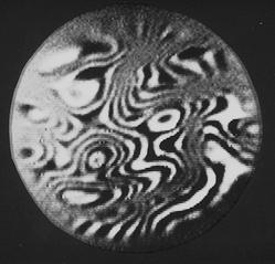
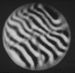
52 Phase-Shifted Fringe Pattern Frame 1 Frame 2 Frame 3 Frame 4 Page 52
53 Surface Measurement Using Phase-Shifting Scatterplate Interferometer Page 53


54 Measurement Comparison Scatterplate WYKO 6000 RMS = Waves PV = Waves RMS = Waves PV = Waves Page 54
55 Scatterplate Interferometer Source Interferogram Focusing Lens Scatterplate (Near center of curvature of mirror being tested) Mirror Under Test Imaging Lens Mirror Ref: A.H. Shoemaker and M.V.R.K. Murty, Appl. Opt., 5, p. 603, Page 55

56 8.2.7 Smartt Point Diffraction Interferometer (PDI) World s Simplest Interferometer Incident wavefront diffracted wavefront reference wave Focusing lens Transmitted test wave Interferogram Point Diffractor D = ½ Airy Disk Diameter Generates synthetic reference wave from point diffracting element Page 56
57 Changing Tilt and Defocus of PDI Page 57

58 Changing Tilt Reduces Fringe Visibility The major disadvantage of the PDI is that the amount of light in the reference beam depends on the position of the pinhole. Page 58

59 Other Testing Configurations Place the PDI at the location where the source is imaged. Page 59


60 PDI Test Results Interferogram of 0.6-m Cassegrain telescope with a laser source. Interferogram of 1.5m Mount Palomar telescope with a star as source. Ref: R. N. Smartt and W. H. Steel, Japan J. Appl. Phys. 14 (1975) Suppl Page 60
61 How Do We Phase Shift? n Two basic techniques Use diffraction gratings Use polarization techniques Page 61

62 Phase-Shifting Point Diffraction Interferometer (Modified Smartt Interferometer) Spatially coherent illumination by pinhole diffraction transmitted intensity interferogram Ref: J. Bokor Coarse grating beam splitter Grating translation produces phase-shifting Page 62
63 Multichannel Phase-Shifted PDI Ref: O. Kwon, Opt. Lett (1978) Page 63

64 Measurement Results Page 64
65 Use of Half-Wave Plate PDI Aberrated Focus Spot Clear Pinhole Test Wavefront p(+δ) s Test Wavefront s p(+δ) Half-Wave Plate Semitransparent Region Reference Wavefront s p(+δ) Page 65
66 One Experimental Setup of Half-Wave Plate PDI Polarizer (0 o ) EOM (O o ) Test Lens PDI (45 o ) Imaging Optics Rotating Ground Glass Plate Laser CCD Camera HWP (22.5 o ) Source s Spatial Filter p (+δ) s Reference p (+δ) Analyzer (0 o ) p (+δ) s p (+δ) Imaging Optics Test s Ref: Robert M. Neal and James C. Wyant APPLIED OPTICS, Vol. 45, page 3463, 20 May 2006 Page 66
67 Liquid-Crystal PDI Plastic microsphere in liquid crystal Page 67

 Page")
68 Test Results Five phase shifted frames Ref: C. Mercer and K. Creath, Opt. Lett. 19, 916 (1994) Page 68

69 Lithium Niobate Crystal PDI Pinhole etched in lithium niobate Ref: P. Ferraro, M. Paturzo, and S. Grilli, 1 March 2007 SPIE Newsroom Page 69

70 Instantaneous Phase-Shifting PDI Incident wavefront Test beam (transmitted) PhaseCam Interferometer Primary lens Polarization point diffraction plate Synthetic Reference Beam Synthetic reference wave is p-polarized Transmitted test beam is s-polarized Wavefront can be measured in a single shot! Page 70
71 Polarization PDI Construction Finite Conducting Grids wire grid polarizer Wire grid horizontal Wire grid vertical Substrate Page 71

72 Single Layer PDI Example 3um Focused Ion Beam Milling Page 72
 Output polarizer (y) Diffracting aperture Contrast ratio >1000:1, independent")
73 Polarization PDI Multilayer Design Input polarizer (x) Substrate Pol. rotation (45 deg x-y plane) Output polarizer (y) Diffracting aperture Contrast ratio >1000:1, independent of input polarization 500 nm Page 73


74 Air Flow Measurement Simultaneous Interferograms Phase Map Page 74
75 8.2.8 Sommargren Diffraction Interferometer Short coherence length source Optical fiber Optic under test Variable neutral density filter Variable length Half-wave plate Microscope objective Imaging lens CCD camera Polarizer Polarization beamsplitter Interference pattern Quarter-wave plates Computer system PZT Phase Shifting Diffraction Interferometer (PSDI) configured to measure the surface figure of a concave off-axis aspheric mirror. Page 75


76 Detail of the Diffracted and Reflected Wavefronts at the End of the Fiber Page 76
77 8.2.9 Measurement of Cylindrical Surfaces Need cylindrical wavefront Reference grating: Off-axis cylinder Cylinder null lens: Hard to make Direct measurement - No modifications to interferometer Concave and convex surfaces Quantitative - phase measurement Page 77
78 Cylinder Null Lens Test Setup Collimated Beam Reference Surface Cylinder Diverger Lens Test Cylinder (Angle Critical) Page 78
79 Cylinder Grating Test Setup Transmission Flat Reference Surface Collimated Beam Cylinder Grating Test Cylinder (Angle Critical) 1st Order From Grating Grating Lines Page 79
80 Long-Wavelength Interferometry n Wavelengths of primary interest n Test infrared transmitting optics n Test optically rough surfaces Page 80
81 Wavelengths of Primary Interest 1.06 microns Reduced sensitivity 10.6 microns Reduced sensitivity Test infrared transmitting optics Testing optically rough surfaces Page 81
82 1.06 Micron Source Interferometer Diode Pumped Yag Laser Excellent coherence properties Normal Optics Normal CCD Camera Conventional interferometry techniques work well. Page 82
83 10.6 Micron Source Interferometer Carbon Dioxide Laser Excellent coherence properties Zinc Selenide or Germanium Optics Bolometer Conventional interferometry techniques work well. Page 83


84 Reduced Sensitivity Testing microns wavelength 10.6 microns wavelength Page 84
85 Testing Rough Surfaces Assume surface height distribution is Gaussian with standard deviation σ. The normal probability distribution for the height, h, is p ( h ) = 1 exp (- ( 2 π ) 1 / 2 σ h 2 2 σ 2 ) Page 85
86 Fringe Contrast Reduction due to Surface Roughness The fringe contrast reduction due to surface roughness is C = exp ( - 8 π 2 σ 2 / λ 2 ) Reference: Appl. Opt. 11, 1862 (1980). Page 86
87 Fringe Contrast versus Surface Roughness - Theory Surface Roughness (σ/λ) Page 87
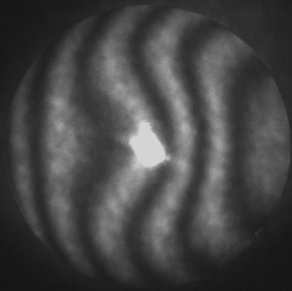
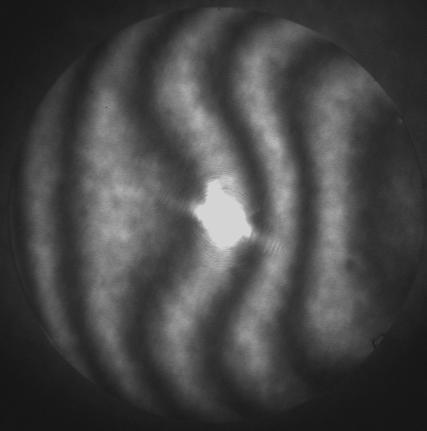
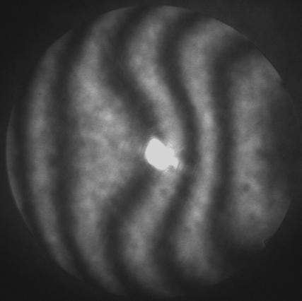
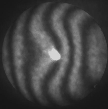
88 Interferograms Obtained for Different Roughness Surfaces σ = 0 µm, C = 1.0 σ = 0.32 µm, C = 0.93 σ = 0.44 µm, C = 0.87 σ = 0.93 µm, C = 0.54 σ = 1.44 µm, C = 0.23 σ = 1.85 µm, C = 0.07 Page 88
89 Fringe Contrast versus Surface Roughness - Theory and Experiment Surface Roughness (σ/λ) Page 89

90 Infrared Interferograms of Off-Axis Parabolic Mirror in Chronological Order Page 90

91 10.6 Micron Wavelength Interferometer Page 91
OPTI 513R / Optical Testing
 OPTI 513R / Optical Testing Instructor: Dae Wook Kim Meinel Building Rm 633, University of Arizona, Tucson, AZ 85721 E-Mail: dkim@optics.arizona.edu Website: sites.google.com/site/opti513r/ Office Hours:
Optics Vac Work MT 2008
 Optics Vac Work MT 2008 1. Explain what is meant by the Fraunhofer condition for diffraction. [4] An aperture lies in the plane z = 0 and has amplitude transmission function T(y) independent of x. It is
2011 Optical Science & Engineering PhD Qualifying Examination Optical Sciences Track: Advanced Optics Time allowed: 90 minutes
 2011 Optical Science & Engineering PhD Qualifying Examination Optical Sciences Track: Advanced Optics Time allowed: 90 minutes Answer all four questions. All questions count equally. 3(a) A linearly polarized
Chapter 82 Example and Supplementary Problems
 Chapter 82 Example and Supplementary Problems Nature of Polarized Light: 1) A partially polarized beam is composed of 2.5W/m 2 of polarized and 4.0W/m 2 of unpolarized light. Determine the degree of polarization
A. K. Srivastava, K.C. Sati, Satyander Kumar alaser Science and Technology Center, Metcalfe House, Civil Lines, Delhi , INDIA
 International Journal of Scientific & Engineering Research Volume 8, Issue 7, July-2017 1752 Optical method for measurement of radius of curvature of large diameter mirrors A. K. Srivastava, K.C. Sati,
9.0 Special Interferometric Tests for Aspherical Surfaces
 9.0 Special Interferometric Tests for Aspherical Surfaces 9.0 Special Interferometric Tests for Aspherical Surfaces - I n 9.1 Aspheric Surfaces 9.1.1 Conic 9.1.2 Sag for Aspheres n 9.2 Null Test 9.2.1
Chapter 36. Image Formation
 Chapter 36 Image Formation Apr 22, 2012 Light from distant things We learn about a distant thing from the light it generates or redirects. The lenses in our eyes create images of objects our brains can
Polarizers. Laser Polarizers Broadband Polarizing Beamsplitting Cubes 78 Narrowband Polarizing Beamsplitting Cubes 79
 Prisms Introduction to Right Angle Prisms 72 Quality Right Angle Prisms 73 Laboratory Quality Right Angle Prisms 73 Equilateral Prisms 74 Wedge Prisms 75 Anamorphic Prism Pair 75 Penta Prisms 76 Dove Prisms
OC - Optical Components
 99 OC - Optical Components 1 OC-0005 Biconcave lens f=-5 mm, C25 mount A biconcave lens with a diameter of 5 mm and a focal length of -5 mm is mounted into a C25 mount with a free opening of 4 mm. 2 OC-0010
Null test for a highly paraboloidal mirror
 Null test for a highly paraboloidal mirror Taehee Kim, James H. Burge, Yunwoo Lee, and Sungsik Kim A circular null computer-generated hologram CGH was used to test a highly paraboloidal mirror diameter,
Coherent Gradient Sensing Microscopy: Microinterferometric Technique. for Quantitative Cell Detection
 Coherent Gradient Sensing Microscopy: Microinterferometric Technique for Quantitative Cell Detection Proceedings of the SEM Annual Conference June 7-10, 010 Indianapolis, Indiana USA 010 Society for Experimental
Testing spherical surfaces: a fast, quasi-absolute technique
 Testing spherical surfaces: a fast, quasi-absolute technique Katherine Creath and James C. Wyant A technique for measuring the quality of spherical surfaces that provides a quasi-absolute result is presented.
Measurement of Highly Parabolic Mirror using Computer Generated Hologram
 Measurement of Highly Parabolic Mirror using Computer Generated Hologram Taehee Kim a, James H. Burge b, Yunwoo Lee c a Digital Media R&D Center, SAMSUNG Electronics Co., Ltd., Suwon city, Kyungki-do,
INTERFERENCE. (i) When the film is quite thin as compared to the wavelength of light,
 When the film is quite thin as compared to the wavelength of light,") (a) Reflected System: For the thin film in air the ray BG suffers reflection at air medium (rare to denser) boundary, it undergoes a phase change of π and a path change of λ/2, while the ray DF does not,
(a) Reflected System: For the thin film in air the ray BG suffers reflection at air medium (rare to denser) boundary, it undergoes a phase change of π and a path change of λ/2, while the ray DF does not,
Interference with polarized light
 Interference with polarized light Summary of the previous lecture (see lecture 3 - slides 12 to 25) With polarized light E 1 et E 2 are complex amplitudes: E 1 + E 2 e iϕ 2 = E 1 2 + E 2 2 + 2 Re(E 1 *
AP* Optics Free Response Questions
 AP* Optics Free Response Questions 1978 Q5 MIRRORS An object 6 centimeters high is placed 30 centimeters from a concave mirror of focal length 10 centimeters as shown above. (a) On the diagram above, locate
SIMULATION AND VISUALIZATION IN THE EDUCATION OF COHERENT OPTICS
 SIMULATION AND VISUALIZATION IN THE EDUCATION OF COHERENT OPTICS J. KORNIS, P. PACHER Department of Physics Technical University of Budapest H-1111 Budafoki út 8., Hungary e-mail: kornis@phy.bme.hu, pacher@phy.bme.hu
Light: Geometric Optics
 Light: Geometric Optics The Ray Model of Light Light very often travels in straight lines. We represent light using rays, which are straight lines emanating from an object. This is an idealization, but
Dual Mode Interferometer for Measuring Dynamic Displacement of Specular and Diffuse Components
 Dual Mode Interferometer for Measuring Dynamic Displacement of Specular and Diffuse Components Michael North Morris, Tim Horner, Markar Naradikian, Joe Shiefman 4D Technology Corporation, 3280 E. Hemisphere
Ray Optics I. Last time, finished EM theory Looked at complex boundary problems TIR: Snell s law complex Metal mirrors: index complex
 Phys 531 Lecture 8 20 September 2005 Ray Optics I Last time, finished EM theory Looked at complex boundary problems TIR: Snell s law complex Metal mirrors: index complex Today shift gears, start applying
Chapter 2: Wave Optics
 Chapter : Wave Optics P-1. We can write a plane wave with the z axis taken in the direction of the wave vector k as u(,) r t Acos tkzarg( A) As c /, T 1/ and k / we can rewrite the plane wave as t z u(,)
index of refraction-light speed
 AP Physics Study Guide Chapters 22, 23, 24 Reflection, Refraction and Interference Name Write each of the equations specified below, include units for all quantities. Law of Reflection Lens-Mirror Equation
4D Technology Corporation
 4D Technology Corporation Dynamic Laser Interferometry for Company Profile Disk Shape Characterization DiskCon Asia-Pacific 2006 Chip Ragan chip.ragan@4dtechnology.com www.4dtechnology.com Interferometry
Tutorial Solutions. 10 Holographic Applications Holographic Zone-Plate
 10 Holographic Applications 10.1 Holographic Zone-Plate Tutorial Solutions Show that if the intensity pattern for on on-axis holographic lens is recorded in lithographic film, then a one-plate results.
Phy 133 Section 1: f. Geometric Optics: Assume the rays follow straight lines. (No diffraction). v 1 λ 1. = v 2. λ 2. = c λ 2. c λ 1.
. v 1 λ 1. = v 2. λ 2. = c λ 2. c λ 1.") Phy 133 Section 1: f Geometric Optics: Assume the rays follow straight lines. (No diffraction). Law of Reflection: θ 1 = θ 1 ' (angle of incidence = angle of reflection) Refraction = bending of a wave
Phy 133 Section 1: f Geometric Optics: Assume the rays follow straight lines. (No diffraction). Law of Reflection: θ 1 = θ 1 ' (angle of incidence = angle of reflection) Refraction = bending of a wave
E x Direction of Propagation. y B y
 x E x Direction of Propagation k z z y B y An electromagnetic wave is a travelling wave which has time varying electric and magnetic fields which are perpendicular to each other and the direction of propagation,
Chapter 7: Geometrical Optics
 Chapter 7: Geometrical Optics 7. Reflection at a Spherical Surface L.O 7.. State laws of reflection Laws of reflection state: L.O The incident ray, the reflected ray and the normal all lie in the same
Mirror Example Consider a concave mirror radius -10 cm then = = Now consider a 1 cm candle s = 15 cm from the vertex Where is the image.
 Mirror Example Consider a concave mirror radius -10 cm then r 10 f = = = 5 cm 2 2 Now consider a 1 cm candle s = 15 cm from the vertex Where is the image 1 s 2 1 = = r s 1 1 2 + = = s s r 1 1 = 0.13333
INTERFERENCE. where, m = 0, 1, 2,... (1.2) otherwise, if it is half integral multiple of wavelength, the interference would be destructive.
 otherwise, if it is half integral multiple of wavelength, the interference would be destructive.") 1.1 INTERFERENCE When two (or more than two) waves of the same frequency travel almost in the same direction and have a phase difference that remains constant with time, the resultant intensity of light
1.1 INTERFERENCE When two (or more than two) waves of the same frequency travel almost in the same direction and have a phase difference that remains constant with time, the resultant intensity of light
UNIT VI OPTICS ALL THE POSSIBLE FORMULAE
 58 UNIT VI OPTICS ALL THE POSSIBLE FORMULAE Relation between focal length and radius of curvature of a mirror/lens, f = R/2 Mirror formula: Magnification produced by a mirror: m = - = - Snell s law: 1
Invited Paper. Katherine Creath and James C. Wyant WYKO Corporation 2650 East Elvira Road, Tucson, Arizona ABSTRACT 1. INTRODUCTION.
 Invited Paper Absolute Measurement of Spherical Surfaces Katherine Creath and James C. Wyant WYKO Corporation 2650 East Elvira Road, Tucson, Arizona 85706 ABSTRACT The testing of spherical surfaces using
specular diffuse reflection.
 Lesson 8 Light and Optics The Nature of Light Properties of Light: Reflection Refraction Interference Diffraction Polarization Dispersion and Prisms Total Internal Reflection Huygens s Principle The Nature
Basic optics. Geometrical optics and images Interference Diffraction Diffraction integral. we use simple models that say a lot! more rigorous approach
 Basic optics Geometrical optics and images Interference Diffraction Diffraction integral we use simple models that say a lot! more rigorous approach Basic optics Geometrical optics and images Interference
Chapter 24. Wave Optics. Wave Optics. The wave nature of light is needed to explain various phenomena
 Chapter 24 Wave Optics Wave Optics The wave nature of light is needed to explain various phenomena Interference Diffraction Polarization The particle nature of light was the basis for ray (geometric) optics
White-light interference microscopy: minimization of spurious diffraction effects by geometric phase-shifting
 White-light interference microscopy: minimization of spurious diffraction effects by geometric phase-shifting Maitreyee Roy 1, *, Joanna Schmit 2 and Parameswaran Hariharan 1 1 School of Physics, University
Chapter 7: Geometrical Optics. The branch of physics which studies the properties of light using the ray model of light.
 Chapter 7: Geometrical Optics The branch of physics which studies the properties of light using the ray model of light. Overview Geometrical Optics Spherical Mirror Refraction Thin Lens f u v r and f 2
2/26/2016. Chapter 23 Ray Optics. Chapter 23 Preview. Chapter 23 Preview
 Chapter 23 Ray Optics Chapter Goal: To understand and apply the ray model of light. Slide 23-2 Chapter 23 Preview Slide 23-3 Chapter 23 Preview Slide 23-4 1 Chapter 23 Preview Slide 23-5 Chapter 23 Preview
ECEN 4606, UNDERGRADUATE OPTICS LAB
 ECEN 4606, UNDERGRADUATE OPTICS LAB Lab 5: Interferometry and Coherence SUMMARY: In this lab you will use interference of a temporally coherent (very narrow temporal frequency bandwidth) laser beam to
Lecture 4 Recap of PHYS110-1 lecture Physical Optics - 4 lectures EM spectrum and colour Light sources Interference and diffraction Polarization
 Lecture 4 Recap of PHYS110-1 lecture Physical Optics - 4 lectures EM spectrum and colour Light sources Interference and diffraction Polarization Lens Aberrations - 3 lectures Spherical aberrations Coma,
Chapter 37. Wave Optics
 Chapter 37 Wave Optics Wave Optics Wave optics is a study concerned with phenomena that cannot be adequately explained by geometric (ray) optics. Sometimes called physical optics These phenomena include:
AP Physics: Curved Mirrors and Lenses
 The Ray Model of Light Light often travels in straight lines. We represent light using rays, which are straight lines emanating from an object. This is an idealization, but is very useful for geometric
Chapter 37. Interference of Light Waves
 Chapter 37 Interference of Light Waves Wave Optics Wave optics is a study concerned with phenomena that cannot be adequately explained by geometric (ray) optics These phenomena include: Interference Diffraction
Diffraction. Single-slit diffraction. Diffraction by a circular aperture. Chapter 38. In the forward direction, the intensity is maximal.
 Diffraction Chapter 38 Huygens construction may be used to find the wave observed on the downstream side of an aperture of any shape. Diffraction The interference pattern encodes the shape as a Fourier
Full surface strain measurement using shearography
 Full surface strain measurement using shearography Roger M. Groves, Stephen W. James * and Ralph P. Tatam Centre for Photonics and Optical Engineering, School of Engineering, Cranfield University ABSTRACT
Calibration of a portable interferometer for fiber optic connector endface measurements
 Calibration of a portable interferometer for fiber optic connector endface measurements E. Lindmark Ph.D Light Source Reference Mirror Beamsplitter Camera Calibrated parameters Interferometer Interferometer
Chapter 24. Wave Optics. Wave Optics. The wave nature of light is needed to explain various phenomena
 Chapter 24 Wave Optics Wave Optics The wave nature of light is needed to explain various phenomena Interference Diffraction Polarization The particle nature of light was the basis for ray (geometric) optics
Distortion Correction for Conical Multiplex Holography Using Direct Object-Image Relationship
 Proc. Natl. Sci. Counc. ROC(A) Vol. 25, No. 5, 2001. pp. 300-308 Distortion Correction for Conical Multiplex Holography Using Direct Object-Image Relationship YIH-SHYANG CHENG, RAY-CHENG CHANG, AND SHIH-YU
9. Polarizers. Index of. Coefficient of Material Wavelength ( ) Brewster angle refraction (n)
 Brewster angle refraction (n)") 9. Polarizers All polarized light is to some degree elliptical in nature. Basic states of polarization like linear and circular are actually special cases of elliptically polarized light which is defined
9. Polarizers All polarized light is to some degree elliptical in nature. Basic states of polarization like linear and circular are actually special cases of elliptically polarized light which is defined
Development of shape measuring system using a line sensor in a lateral shearing interferometer
 Development of shape measuring system using a line sensor in a lateral shearing interferometer Takashi NOMURA*a, Kazuhide KAMIYA*a, Akiko NAGATA*a, Hatsuzo TASHIRO **b, Seiichi OKUDA ***c a Toyama Prefectural
OPTICS MIRRORS AND LENSES
 Downloaded from OPTICS MIRRORS AND LENSES 1. An object AB is kept in front of a concave mirror as shown in the figure. (i)complete the ray diagram showing the image formation of the object. (ii) How will
Chapter 8: Physical Optics
 Chapter 8: Physical Optics Whether light is a particle or a wave had puzzled physicists for centuries. In this chapter, we only analyze light as a wave using basic optical concepts such as interference
Basic Optics : Microlithography Optics Part 4: Polarization
 Electromagnetic Radiation Polarization: Linear, Circular, Elliptical Ordinary and extraordinary rays Polarization by reflection: Brewster angle Polarization by Dichroism Double refraction (Birefringence)
MICHELSON S INTERFEROMETER
 MICHELSON S INTERFEROMETER Objectives: 1. Alignment of Michelson s Interferometer using He-Ne laser to observe concentric circular fringes 2. Measurement of the wavelength of He-Ne Laser and Na lamp using
Chapter 24. Wave Optics
 Chapter 24 Wave Optics Wave Optics The wave nature of light is needed to explain various phenomena Interference Diffraction Polarization The particle nature of light was the basis for ray (geometric) optics
OPSE FINAL EXAM Fall CLOSED BOOK. Two pages (front/back of both pages) of equations are allowed.
 of equations are allowed.") CLOSED BOOK. Two pages (front/back of both pages) of equations are allowed. YOU MUST SHOW YOUR WORK. ANSWERS THAT ARE NOT JUSTIFIED WILL BE GIVEN ZERO CREDIT. ALL NUMERICAL ANSERS MUST HAVE UNITS INDICATED.
CLOSED BOOK. Two pages (front/back of both pages) of equations are allowed. YOU MUST SHOW YOUR WORK. ANSWERS THAT ARE NOT JUSTIFIED WILL BE GIVEN ZERO CREDIT. ALL NUMERICAL ANSERS MUST HAVE UNITS INDICATED.
Hyperspectral interferometry for single-shot absolute measurement of 3-D shape and displacement fields
 EPJ Web of Conferences 6, 6 10007 (2010) DOI:10.1051/epjconf/20100610007 Owned by the authors, published by EDP Sciences, 2010 Hyperspectral interferometry for single-shot absolute measurement of 3-D shape
Light: Geometric Optics (Chapter 23)
") Light: Geometric Optics (Chapter 23) Units of Chapter 23 The Ray Model of Light Reflection; Image Formed by a Plane Mirror Formation of Images by Spherical Index of Refraction Refraction: Snell s Law 1
Light: Geometric Optics (Chapter 23) Units of Chapter 23 The Ray Model of Light Reflection; Image Formed by a Plane Mirror Formation of Images by Spherical Index of Refraction Refraction: Snell s Law 1
Nicholas J. Giordano. Chapter 24. Geometrical Optics. Marilyn Akins, PhD Broome Community College
 Nicholas J. Giordano www.cengage.com/physics/giordano Chapter 24 Geometrical Optics Marilyn Akins, PhD Broome Community College Optics The study of light is called optics Some highlights in the history
Part 7 Holography. Basic Hologram Setup
 Part 7 Holography Basic Holographic Technique Light Sources Recording Materials Holographic Non-Destructive Testing Real-Time Double-Exposure Time-Average 2000 - James C. Wyant Part 7 Page 1 of 28 Basic
Conceptual Physics Fundamentals
 Conceptual Physics Fundamentals Chapter 14: PROPERTIES OF LIGHT This lecture will help you understand: Reflection Refraction Dispersion Total Internal Reflection Lenses Polarization Properties of Light
Intermediate Physics PHYS102
 Intermediate Physics PHYS102 Dr Richard H. Cyburt Assistant Professor of Physics My office: 402c in the Science Building My phone: (304) 384-6006 My email: rcyburt@concord.edu My webpage: www.concord.edu/rcyburt
Basic Polarization Techniques and Devices 1998, 2003 Meadowlark Optics, Inc
 Basic Polarization Techniques and Devices 1998, 2003 Meadowlark Optics, Inc This application note briefly describes polarized light, retardation and a few of the tools used to manipulate the polarization
Section 2. Mirror and Prism Systems
 2-1 Section 2 Mirror and Prism Systems Plane Mirrors Plane mirrors are used to: Produce a deviation Fold the optical path Change the image parity Each ray from the object point obeys the law of reflection
Single Photon Interference
 December 19, 2006 D. Lancia P. McCarthy Classical Interference Intensity Distribution Overview Quantum Mechanical Interference Probability Distribution Which Path? The Effects of Making a Measurement Wave-Particle
Chapter 38. Diffraction Patterns and Polarization
 Chapter 38 Diffraction Patterns and Polarization Diffraction Light of wavelength comparable to or larger than the width of a slit spreads out in all forward directions upon passing through the slit This
PHYSICS. Chapter 34 Lecture FOR SCIENTISTS AND ENGINEERS A STRATEGIC APPROACH 4/E RANDALL D. KNIGHT
 PHYSICS FOR SCIENTISTS AND ENGINEERS A STRATEGIC APPROACH 4/E Chapter 34 Lecture RANDALL D. KNIGHT Chapter 34 Ray Optics IN THIS CHAPTER, you will learn about and apply the ray model of light Slide 34-2
Physics 214 Midterm Fall 2003 Form A
 1. A ray of light is incident at the center of the flat circular surface of a hemispherical glass object as shown in the figure. The refracted ray A. emerges from the glass bent at an angle θ 2 with respect
Lecture PowerPoints. Chapter 24 Physics: Principles with Applications, 7 th edition Giancoli
 Lecture PowerPoints Chapter 24 Physics: Principles with Applications, 7 th edition Giancoli This work is protected by United States copyright laws and is provided solely for the use of instructors in teaching
Waves & Oscillations
 Physics 42200 Waves & Oscillations Lecture 37 Interference Spring 2016 Semester Matthew Jones Multiple Beam Interference In many situations, a coherent beam can interfere with itself multiple times Consider
Light: Geometric Optics
 Light: Geometric Optics 23.1 The Ray Model of Light Light very often travels in straight lines. We represent light using rays, which are straight lines emanating from an object. This is an idealization,
3.6 Rotational-Shearing Interferometry for Improved Target Characterization
 3.6 Rotational-Shearing Interferometry for Improved Target Characterization Inertial-fusion targets have strict requirements regarding sphericity, surface smoothness, and layer-thickness uniformity. During
TEAMS National Competition Middle School Version Photometry 25 Questions
 TEAMS National Competition Middle School Version Photometry 25 Questions Page 1 of 13 Telescopes and their Lenses Although telescopes provide us with the extraordinary power to see objects miles away,
Fundamental Optics for DVD Pickups. The theory of the geometrical aberration and diffraction limits are introduced for
 Chapter Fundamental Optics for DVD Pickups.1 Introduction to basic optics The theory of the geometrical aberration and diffraction limits are introduced for estimating the focused laser beam spot of a
Optics. a- Before the beginning of the nineteenth century, light was considered to be a stream of particles.
 Optics 1- Light Nature: a- Before the beginning of the nineteenth century, light was considered to be a stream of particles. The particles were either emitted by the object being viewed or emanated from
TEAMS National Competition High School Version Photometry 25 Questions
 TEAMS National Competition High School Version Photometry 25 Questions Page 1 of 14 Telescopes and their Lenses Although telescopes provide us with the extraordinary power to see objects miles away, the
PY212 Lecture 25. Prof. Tulika Bose 12/3/09. Interference and Diffraction. Fun Link: Diffraction with Ace Ventura
 PY212 Lecture 25 Interference and Diffraction Prof. Tulika Bose 12/3/09 Fun Link: Diffraction with Ace Ventura Summary from last time The wave theory of light is strengthened by the interference and diffraction
Unit 5.C Physical Optics Essential Fundamentals of Physical Optics
 Unit 5.C Physical Optics Essential Fundamentals of Physical Optics Early Booklet E.C.: + 1 Unit 5.C Hwk. Pts.: / 25 Unit 5.C Lab Pts.: / 20 Late, Incomplete, No Work, No Units Fees? Y / N 1. Light reflects
Quantitative Data Extraction using Spatial Fourier Transform in Inversion Shear Interferometer
 Rose-Hulman Institute of Technology Rose-Hulman Scholar Graduate Theses - Physics and Optical Engineering Graduate Theses Summer 8-2014 Quantitative Data Extraction using Spatial Fourier Transform in Inversion
Ping Zhou. Copyright Ping Zhou A Dissertation Submitted to the Faculty of the. In Partial Fulfillment of the Requirements For the Degree of
 ERROR ANALYSIS AND DATA REDUCTION FOR INTERFEROMETRIC SURFACE MEASUREMENTS by Ping Zhou Copyright Ping Zhou 29 A Dissertation Submitted to the Faculty of the COLLEGE OF OPTICAL SCIENCES In Partial Fulfillment
dq dt I = Irradiance or Light Intensity is Flux Φ per area A (W/m 2 ) Φ =
 Φ =") Radiometry (From Intro to Optics, Pedrotti -4) Radiometry is measurement of Emag radiation (light) Consider a small spherical source Total energy radiating from the body over some time is Q total Radiant
Radiometry (From Intro to Optics, Pedrotti -4) Radiometry is measurement of Emag radiation (light) Consider a small spherical source Total energy radiating from the body over some time is Q total Radiant
Interference of Light
 Interference of Light Young s Double-Slit Experiment If light is a wave, interference effects will be seen, where one part of wavefront can interact with another part. One way to study this is to do a
Textbook Reference: Glencoe Physics: Chapters 16-18
 Honors Physics-121B Geometric Optics Introduction: A great deal of evidence suggests that light travels in straight lines. A source of light like the sun casts distinct shadows. We can hear sound from
HW Chapter 20 Q 2,3,4,5,6,10,13 P 1,2,3. Chapter 20. Classic and Modern Optics. Dr. Armen Kocharian
 HW Chapter 20 Q 2,3,4,5,6,10,13 P 1,2,3 Chapter 20 Classic and Modern Optics Dr. Armen Kocharian Electromagnetic waves and matter: A Brief History of Light 1000 AD It was proposed that light consisted
Willis High School Physics Workbook Unit 7 Waves and Optics
 Willis High School Physics Workbook Unit 7 Waves and Optics This workbook belongs to Period Waves and Optics Pacing Guide DAY DATE TEXTBOOK PREREADING CLASSWORK HOMEWORK ASSESSMENT M 2/25 T 2/26 W 2/27
Applications of Piezo Actuators for Space Instrument Optical Alignment
 Year 4 University of Birmingham Presentation Applications of Piezo Actuators for Space Instrument Optical Alignment Michelle Louise Antonik 520689 Supervisor: Prof. B. Swinyard Outline of Presentation
Where n = 0, 1, 2, 3, 4
 Syllabus: Interference and diffraction introduction interference in thin film by reflection Newton s rings Fraunhofer diffraction due to single slit, double slit and diffraction grating Interference 1.
Chapter 26 Geometrical Optics
 Chapter 26 Geometrical Optics 26.1 The Reflection of Light 26.2 Forming Images With a Plane Mirror 26.3 Spherical Mirrors 26.4 Ray Tracing and the Mirror Equation 26.5 The Refraction of Light 26.6 Ray
INFLUENCE OF CURVATURE ILLUMINATION WAVEFRONT IN QUANTITATIVE SHEAROGRAPHY NDT MEASUREMENT
 1 th A-PCNDT 6 Asia-Pacific Conference on NDT, 5 th 1 th Nov 6, Auckland, New Zealand INFLUENCE OF CURVATURE ILLUMINATION WAVEFRONT IN QUANTITATIVE SHEAROGRAPHY NDT MEASUREMENT Wan Saffiey Wan Abdullah
Winter College on Optics in Environmental Science February Adaptive Optics: Introduction, and Wavefront Correction
 2018-23 Winter College on Optics in Environmental Science 2-18 February 2009 Adaptive Optics: Introduction, and Wavefront Correction Love G. University of Durham U.K. Adaptive Optics: Gordon D. Love Durham
Chapter 32 Light: Reflection and Refraction. Copyright 2009 Pearson Education, Inc.
 Chapter 32 Light: Reflection and Refraction Units of Chapter 32 The Ray Model of Light Reflection; Image Formation by a Plane Mirror Formation of Images by Spherical Mirrors Index of Refraction Refraction:
Physics 1C, Summer 2011 (Session 1) Practice Midterm 2 (50+4 points) Solutions
 Practice Midterm 2 (50+4 points) Solutions") Physics 1C, Summer 2011 (Session 1) Practice Midterm 2 (50+4 points) s Problem 1 (5x2 = 10 points) Label the following statements as True or False, with a one- or two-sentence explanation for why you chose
Physics 1C, Summer 2011 (Session 1) Practice Midterm 2 (50+4 points) s Problem 1 (5x2 = 10 points) Label the following statements as True or False, with a one- or two-sentence explanation for why you chose
Chapter 33 Continued Properties of Light. Law of Reflection Law of Refraction or Snell s Law Chromatic Dispersion Brewsters Angle
 Chapter 33 Continued Properties of Light Law of Reflection Law of Refraction or Snell s Law Chromatic Dispersion Brewsters Angle Dispersion: Different wavelengths have different velocities and therefore
AP Physics Problems -- Waves and Light
 AP Physics Problems -- Waves and Light 1. 1975-4 (Physical Optics) a. Light of a single wavelength is incident on a single slit of width w. (w is a few wavelengths.) Sketch a graph of the intensity as
Person s Optics Test SSSS
 Person s Optics Test SSSS 2017-18 Competitors Names: School Name: All questions are worth one point unless otherwise stated. Show ALL WORK or you may not receive credit. Include correct units whenever
Surface and thickness measurement of a transparent film using wavelength scanning interferometry
 Surface and thickness measurement of a transparent film using wavelength scanning interferometry Feng Gao, Hussam Muhamedsalih, and Xiangqian Jiang * Centre for Precision Technologies, University of Huddersfield,
Michelson Interferometer
 Michelson Interferometer The Michelson interferometer uses the interference of two reflected waves The third, beamsplitting, mirror is partially reflecting ( half silvered, except it s a thin Aluminum
Winmeen Tnpsc Group 1 & 2 Self Preparation Course Physics UNIT 9. Ray Optics. surface at the point of incidence, all lie in the same plane.
 Laws of reflection Physics UNIT 9 Ray Optics The incident ray, the reflected ray and the normal drawn to the reflecting surface at the point of incidence, all lie in the same plane. The angle of incidence
All forms of EM waves travel at the speed of light in a vacuum = 3.00 x 10 8 m/s This speed is constant in air as well
 Pre AP Physics Light & Optics Chapters 14-16 Light is an electromagnetic wave Electromagnetic waves: Oscillating electric and magnetic fields that are perpendicular to the direction the wave moves Difference
Control of Light. Emmett Ientilucci Digital Imaging and Remote Sensing Laboratory Chester F. Carlson Center for Imaging Science 8 May 2007
 Control of Light Emmett Ientilucci Digital Imaging and Remote Sensing Laboratory Chester F. Carlson Center for Imaging Science 8 May 007 Spectro-radiometry Spectral Considerations Chromatic dispersion
dq dt I = Irradiance or Light Intensity is Flux Φ per area A (W/m 2 ) Φ =
 Φ =") Radiometry (From Intro to Optics, Pedrotti -4) Radiometry is measurement of Emag radiation (light) Consider a small spherical source Total energy radiating from the body over some time is Q total Radiant
Radiometry (From Intro to Optics, Pedrotti -4) Radiometry is measurement of Emag radiation (light) Consider a small spherical source Total energy radiating from the body over some time is Q total Radiant