2.76 / Lecture 5: Large/micro scale
|
|
|
- Blaise Walsh
- 6 years ago
- Views:
Transcription


1 2.76 / Lecture 5: Large/micro scale Constraints Micro-fabrication Micro-physics scaling Assignment
2 Nano Micro Meso Macro Nano Nano Nano Micro Nano Meso Nano Macro Micro Nano Micro Micro Micro Meso Micro Macro Meso Nano Meso Micro Meso Meso Meso Macro Macro Nano Macro Micro Macro Meso Macro Macro Nano Micro Meso Macro I I I I SR f SR f SR f SR f SR f SR f SR f SR f SR f SR f SR f SR f SR f SR f SR f SR f O O O O = Purpose of today Finish mechanical gain factors to make big machines work with little machines Micro-scale flow/interface dominators Micro-scale fabrication Micro-scale surface/volume physics
3 Constraints
4 Constraint-based design Constraint-based compliant mechanism design STEP 1: Design requirements Motion path, stiffness, load capacity, etc Photo removed for copyright reasons. Compliant test rig for automotive steering column. STEP 2: Motion path decomposition Arcs, lines, rotation pts. sub-paths STEP 3:Kinematic parametric concepts Motions, constraint metric, symmetry, etc. STEP 4:Constraint-motion addition rules Serial, parallel, hybrid STEP 5: Topology concept generation Path & constraint driven STEP 6: Concept selection phase I Path errors & over constraint STEP 7: Size and shape optimization Stiffness, load capacity, efficiency, etc STEP 8: Concept selection phase II Direct comparison with design requirements
5 Exact constraint At some scale, everything is a mechanism Exact constraint: Achieve desired motion By applying minimum number of constraints Arranging constraints in optimum topology Adding constraints only when necessary Visualization is critical, this is not cookbook For now: Start with ideal constraints Considering small motions Constraints = lines Figure: Layton Hales PhD Thesis, MIT.
6 Constraint fundamentals Rigid bodies have 6 DOF DOC = # of linearly independent constraints DOF = 6 - DOC A linear displacement can be visualized as a rotation about a point which is far away Figure: Layton Hales PhD Thesis, MIT.

7 Statements Points on a constraint line move perpendicular to the constraint line Figure: Layton Hales PhD Thesis, MIT. Constraints along this line are equivalent Diagram removed for copyright reasons. Source: Blanding, D. L. Exact Constraint: Machine Design using Kinematic Principles. New York: ASME Press, 1999.
8 Statements Intersecting, same-plane constraints are equivalent to other same-plane intersecting constraints Instant centers are powerful tool for visualization, diagnosis, & synthesis
9 Abbe error Error due to magnified moment arm r
10 Statements Constraints remove rotational degree of freedom Length of moment arm determines the quality of the rotational constraint

11 Statements Parallel constraints may be visualized/treated as intersecting at infinity
12 Basic elements Bars Beams Plates Diagrams removed for copyright reasons. Source: Blanding, D. L. Exact Constraint: Machine Design using Kinematic Principles. New York: ASME Press, Notch Hinge
13 Examples Do you really get δz? Figures: Layton Hales PhD Thesis, MIT.
14 Examples Series: Add DOF Follow the serial chain Pick up every DOF Differentiate series by Load path Shared load path = Series This could be 5 DOF Figure: Layton Hales PhD Thesis, MIT. Depends on blade length
15 Examples Parallel: Add Constraints Where there is a common DOF, then have mechanism DOF There are no conflicts in circumferential displacement To θz Non-shared load paths = parallel Figure: Layton Hales PhD Thesis, MIT.
16 Examples Redundancy does not add Degrees of freedom Series Parallel Take care of series first, define them as single element then go through parallel Figure: Layton Hales PhD Thesis, MIT.
17 Examples Parallel z Theta z is a common Degree of freedom All others conflict Figure: Layton Hales PhD Thesis, MIT.
18 Examples δz is a common Degree of freedom Parallel All others conflict Rotation arms cause Conflict in out-of-plane rotations Figure: Layton Hales PhD Thesis, MIT.
19 Over constraint Flexures are often forgiving of over constraint Over constraint = redundant constraint Identifying over constraint How much energy is stored? General metric relating constraint stiffness to motion along constraint K K δ δ CM k CM δ << 1
20 Extension: Fixtures You will need to build a Passive fixture for your STM Kelvin Maxwell Figures: Layton Hales PhD Thesis, MIT.
21 Fixtures as mechanisms Ball far-field point Constraint Groove far-field points Figure: Layton Hales PhD Thesis, MIT.
22 Details of QKC element geometry Figure: Layton Hales PhD Thesis, MIT.
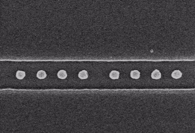
23 Consequences of friction Are kinematic couplings perfect? A B λ Ideal in-plane constraints Real in-plane constraints

![Measured [microns] 50 25](/docs-images/72/66928717/images/24-1.jpg "0-25 -50 Y displacements")

![3 Y error motion 3 2 Y [µm]](/docs-images/72/66928717/images/24-4.jpg "0.2 0.1 Flexure arms 0.0-0.")
24 Flexure grooves reduce friction effect + = x z y 1 Measured [microns] Y displacements Command [microns] 0.3 Y error motion 3 2 Y [µm] Flexure arms Cycle
25 Instant center visualization example Instant center can help you identify how to best constrain or free up a mechanism K K δ δ CM k CM δ << 1 Diagram removed for copyright reasons. Source: Alex Slocum, Precision Machine Design. Poor Good Instant center if ball 1 is removed
26 Examples Is it a wise idea to put three balls in three cones while the balls are rigidly attached to a rigid part? K K δ δ CM k CM δ << 1 Figure: Layton Hales PhD Thesis, MIT.
27 In-plane use of flexures Three balls in three cones What does the constraint diagram look like?
28 Use of flexures to avoid over constraint Flexures provide a very low CM for each joint Energy stored due to over constraint is minimized Energy is channeled through continuously variable Is possible to reach a true minimum Flexure Figure: Layton Hales PhD Thesis, MIT.
29 Low-cost couplings Kinematic elements + OR + Constraint diagrams Manufacturing Diagrams removed for copyright reasons. Cast + Form Tool = Finished Metrics CM Example QKC Joint Metrics 1.0 CM Kr max Kr max [ N /µm ] θ contact


30 Case study: Duratec engine Components Coupling + others 10 µm 5 µm Process Block Pinned joint Assembly Bolts Bedplate QKC Bedplate Block Photos by Prof. Martin Culpepper, courtesy of Ford Motor Company. Used with permission.
31 Micro-scale systems
32 Cross-scale coupling Macro Meso Micro Nano Function Form Flows Physics Fabrication Function Form Flow Physics Fabrication What Geometry Mass Application Compatibility Who Motion Momentum Modeling Quality Why Interfaces Energy Limiting Rate Where Constraints Information Dominant Cost Etc Etc Etc Etc Etc

33 Micro-scale MuSS main challenges Fabrication is fundamentally different Chemical Molecular Ballistic Finished geometry Possible geometries Physics rounding is no longer acceptable Surface forces Thermal time constants Strains
34 General process Wafers Devices Deposition Oxidation or Deposition Lithography Add resist Transfer pattern Remove resist Etch Wet isotropic or Wet anisotropic or RIE Bulk micromachining = Removal of the wafer Surface micromachining = Add/remove layers
35 MiHx fabrication
36 Micro-scale physics For strong dependence on characteristic length, importance of phenomena decreases with characteristic dimension Body L 3 For weaker dependence on characteristic length, phenomena become dominate at small scale Electrostatic L 2 Thermal L Surface tension L 2

37 Micro-scale physics Find the parts ALL of the flows that could exist. Until you gain intuition you must analyze them all with OOM and ratios Take ratio of important flows Apply physics without physics rounding
38 Clean rooms and particles
39 Micro-scale physics: Electrostatics How does electrostatic physics scale? U E = ε o L L 2 z V 2 How does ratio of F Electric scale to F Body? F 1 Electric ~ F L Body What does this mean for MuSS interaction? What happens if you downsize each by factor of 10? What does this mean for the STM project?
40 Micro-scale physics: Thermal How does thermal physics scale? h A T T ( inf ) = ρ c V dt dt Bi = h L k e h A ρ V c t = θ θ inf = T T initial Tinf T inf ρ V c τ ~ L h A Is this a good or a bad thing for MEMS actuators? For the STM?
41 Micro-scale physics: Thermal Cooling Heating
42 Assignment What are the implications for rinsing suspended MEMS devices clean of acids in distilled water? For example you might model a cantilever which of course has a finite stiffness Comment on humidity and MEMS devices 1 page maximum!!! Matweb.com to course secretary by Wednesday 5pm.
2.76 / Lecture 3: Large scale
 2.76 / 2.760 Lecture 3: Large scale Big-small intuition System modeling Big history Big problems Flexures Design experiment 2.76 Multi-scale System Design & Manuacturing itunnel [na] 8 6 4 2 0 2.76 STM
Kinematic Coupling for Precision Fixturing & Assembly
 Kinematic Coupling for Precision Fixturing & Assembly Folkers E. Rojas, MS & Nevan C. Hanumara, PhD MIT 1 February 2013 material from Profs. Alexander H. Slocum & Martin Culpepper http://pergatory.mit.edu/
2.72 Elements of Mechanical Design
 MIT OpenCourseWare http://ocw.mit.edu 2.72 Elements of Mechanical Design Spring 2009 For information about citing these materials or our Terms of Use, visit: http://ocw.mit.edu/terms. 2.72 Elements of
Prof. Alexander Slocum John Hart Pat Willoughby
 Kinematic Couplings and Elastic Averaging Precision, Intelligent, Low Cost Interfaces with Medical Applications? Prof. Alexander Slocum (slocum@mit.edu) John Hart (ajhart@mit.edu) Pat Willoughby (pjwst10@mit.edu)
Chapter 1. Introduction
 Chapter 1. Introduction 1.1 Flexures Flexure mechanisms are a designer s delight. Except for the limits of elasticity, flexures present few other boundaries as far as applications are concerned. Flexures
International Association of Scientific Innovation and Research (IASIR) (An Association Unifying the Sciences, Engineering, and Applied Research)
 (An Association Unifying the Sciences, Engineering, and Applied Research)") International Association of Scientific Innovation and Research (IASIR) (An Association Unifying the Sciences, Engineering, and Applied Research) International Journal of Engineering, Business and Enterprise
International Association of Scientific Innovation and Research (IASIR) (An Association Unifying the Sciences, Engineering, and Applied Research) International Journal of Engineering, Business and Enterprise
Design of a Precision Robot Wrist Interface. Patrick Willoughby Advisor: Alexander Slocum MIT Precision Engineering Research Group
 Design of a Precision Robot Wrist Interface Patrick Willoughby Advisor: Alexander Slocum MIT Precision Engineering Research Group Project Summary Problem: Current bolted robot wrist replacements are inaccurate,
Design and Analysis of a Single Notch Parallelogram Flexure Mechanism Based X-Y Nanopositioning Stage
 Design and Analysis of a Single Notch Parallelogram Flexure Mechanism Based X-Y Nanopositioning Stage Vithun S N *, Narendra Reddy T 1, Prakash Vinod 2, P V Shashikumar 3 Central Manufacturing Technology
ADJUSTABLE GEOMETRIC CONSTRAINTS 2001 MIT PSDAM AND PERG LABS
 ADJUSTABLE GEOMETRIC CONSTRAINTS Why adjust kinematic couplings? KC Repeatability is orders of magnitude better than accuracy Accuracy = f ( manufacture and assemble ) Kinematic Coupling Accuracy Adjusted
Design and Analysis of Compliant Mechanical Amplifier
 ISSN 2395-1621 Design and Analysis of Compliant Mechanical Amplifier #1 Vijay Patil, #2 P. R. Anerao, #3 S. S. Chinchanikar 1 vijaypatil5691@gmail.com 2 prashant.anerao@gmail.com 3 satish091172@gmail.com
Kinematic Design Principles
 Kinematic Design Principles BJ Furman 24SEP97 Introduction Machines and instruments are made up of elements that are suitably arranged and many of which that are movably connected. Two parts that are in
Design and Validation of XY Flexure Mechanism
 Design and Validation of XY Flexure Mechanism 1 Pratik M. Waghmare, 2 Shrishail B. Sollapur 1 Research Scholar, 2 Assistant Professor 1,2 Department of Mechanical Engineering, 1.2 Sinhgad Academy of Engineering,
Principles of Kinematic Constraint
 Principles of Kinematic Constraint For holding a body (rigid thing) with the highest precision, we require: Full 6 DoF constraint If 6 DoFs not fully constrained, then one is loose. No overconstraint Any
MACRO-SCALE PRECISION ALIGNMENT. 3.1 Precision Machine Design Alignment Principles
 Chapter 3 MACRO-SCALE PRECISION ALIGNMENT 3.1 Precision Machine Design Alignment Principles Whenever two solid bodies are positioned with respect to each other, the quality of the alignment can be described
11. Kinematic models of contact Mechanics of Manipulation
 11. Kinematic models of contact Mechanics of Manipulation Matt Mason matt.mason@cs.cmu.edu http://www.cs.cmu.edu/~mason Carnegie Mellon Lecture 11. Mechanics of Manipulation p.1 Lecture 11. Kinematic models
Influence of Geometrical Configuration of Cantilever Structure on Sensitivity of MEMS Resonant Sensors
 Influence of Geometrical Configuration of Cantilever Structure on Sensitivity of MEMS Resonant Sensors Georgeta Ionascu 1, Adriana Sandu 2, Elena Manea 3, Lucian Bogatu 4 1 Professor, Mechatronics & Precision
Design of integrated eccentric mechanisms and exact constraint fixtures for micron-level repeatability and accuracy
 Precision Engineering 29 (2005) 65 80 Design of integrated eccentric mechanisms and exact constraint fixtures for micron-level repeatability and accuracy Martin L. Culpepper, Mangudi Varadarajan Kartik,
Victory Process. Full Physical 3D Semiconductor Simulator Etching and Deposition Simulation
 Victory Process Full Physical 3D Semiconductor Simulator Etching and Deposition Simulation Victory Process 3D Process Simulator Victory Process provides the capability to simulate comprehensive full process
3. Planar kinematics Mechanics of Manipulation
 3. Planar kinematics Mechanics of Manipulation Matt Mason matt.mason@cs.cmu.edu http://www.cs.cmu.edu/~mason Carnegie Mellon Lecture 3. Mechanics of Manipulation p.1 Lecture 2. Planar kinematics. Chapter
Chapter 2 DESIGN OF COUPLING INTERFACES. 2.1 General Coupling Description
 Chapter 2 DESIGN OF COUPLING INTERFACES 2.1 General Coupling Description In precision machine design, one of the most important steps in designing a machine is the consideration of the effect of interfaces
Design and Analyses of a Macro Parallel Robot with Flexure Hinges for Micro Assembly Tasks
 Design and Analyses of a Macro Parallel Robot with Flexure Hinges for Micro Assembly Tasks J. Hesselbach, A. Raatz, J. Wrege, S. Soetebier Institute of Machine Tools and Production Technology IWF Technical
10/25/2018. Robotics and automation. Dr. Ibrahim Al-Naimi. Chapter two. Introduction To Robot Manipulators
 Robotics and automation Dr. Ibrahim Al-Naimi Chapter two Introduction To Robot Manipulators 1 Robotic Industrial Manipulators A robot manipulator is an electronically controlled mechanism, consisting of
Introduction. Section 3: Structural Analysis Concepts - Review
 Introduction In this class we will focus on the structural analysis of framed structures. Framed structures consist of components with lengths that are significantly larger than crosssectional areas. We
Lesson 1: Introduction to Pro/MECHANICA Motion
 Lesson 1: Introduction to Pro/MECHANICA Motion 1.1 Overview of the Lesson The purpose of this lesson is to provide you with a brief overview of Pro/MECHANICA Motion, also called Motion in this book. Motion
Session #5 2D Mechanisms: Mobility, Kinematic Analysis & Synthesis
 Session #5 2D Mechanisms: Mobility, Kinematic Analysis & Synthesis Courtesy of Design Simulation Technologies, Inc. Used with permission. Dan Frey Today s Agenda Collect assignment #2 Begin mechanisms
IMECE FUNCTIONAL INTERFACE-BASED ASSEMBLY MODELING
 Proceedings of IMECE2005 2005 ASME International Mechanical Engineering Congress and Exposition November 5-11, 2005, Orlando, Florida USA IMECE2005-79945 FUNCTIONAL INTERFACE-BASED ASSEMBLY MODELING James
HEXFLEX: A PLANAR MECHANISM FOR SIX-AXIS MANIPULATION AND ALIGNMENT
 HEXFLEX: A PLANAR MECHANISM FOR SIX-AXIS MANIPULATION AND ALIGNMENT Martin L. Culpepper, Gordon Anderson and Patrick Petri Massachusetts Institute of Technolog, Cambridge, MA Kewords: Compliant mechanism,
23. Assembly Mechanics of Manipulation
 23. Assembly Mechanics of Manipulation Matt Mason matt.mason@cs.cmu.edu http://www.cs.cmu.edu/~mason Carnegie Mellon Lecture 23. Mechanics of Manipulation p.1 Lecture 23. Assembly. Chapter 1 Manipulation
Guidelines for proper use of Plate elements
 Guidelines for proper use of Plate elements In structural analysis using finite element method, the analysis model is created by dividing the entire structure into finite elements. This procedure is known
WEEKS 1-2 MECHANISMS
 References WEEKS 1-2 MECHANISMS (METU, Department of Mechanical Engineering) Text Book: Mechanisms Web Page: http://www.me.metu.edu.tr/people/eres/me301/in dex.ht Analitik Çözümlü Örneklerle Mekanizma
MEDIUM SCALE DESIGN CASE STUDY: WRIST INTERFACE. 4.1 Background and Problem Description
 Chapter 4 MEDIUM SCALE DESIGN CASE STUDY: WRIST INTERFACE 4.1 Background and Problem Description 4.1.1 Background Out of the entire line of ABB Robots, the IRB 6400R robot is one of the most versatile
Synthesis and Analysis of Parallel Kinematic XY Flexure Mechanisms
 Synthesis and Analysis of Parallel Kinematic XY Flexure Mechanisms By Shorya Awtar B.Tech., Mechanical Engineering, 1998 Indian Institute of Technology, Kanpur, India M.S., Mechanical Engineering, 2000
Robotics. SAAST Robotics Robot Arms
 SAAST Robotics 008 Robot Arms Vijay Kumar Professor of Mechanical Engineering and Applied Mechanics and Professor of Computer and Information Science University of Pennsylvania Topics Types of robot arms
Manipulation: Mechanisms, Grasping and Inverse Kinematics
 Manipulation: Mechanisms, Grasping and Inverse Kinematics RSS Lectures 14 & 15 Monday & Wednesday, 1 & 3 April 2013 Prof. Seth Teller Overview Mobility and Manipulation Manipulation Strategies Mechanism
Kinematics Fundamentals CREATING OF KINEMATIC CHAINS
 Kinematics Fundamentals CREATING OF KINEMATIC CHAINS Mechanism Definitions 1. a system or structure of moving parts that performs some function 2. is each system reciprocally joined moveable bodies the
High-Accuracy, Quick-Change, Robot Factory Interface
 High-Accuracy, Quick-Change, Robot Factory Interface John Hart (ajhart@mit.edu) Prof. Alexander Slocum, Advisor MIT Precision Engineering Research Group Project Goals Design, test, and demonstrate production
Engineering Effects of Boundary Conditions (Fixtures and Temperatures) J.E. Akin, Rice University, Mechanical Engineering
 J.E. Akin, Rice University, Mechanical Engineering") Engineering Effects of Boundary Conditions (Fixtures and Temperatures) J.E. Akin, Rice University, Mechanical Engineering Here SolidWorks stress simulation tutorials will be re-visited to show how they
Engineering Effects of Boundary Conditions (Fixtures and Temperatures) J.E. Akin, Rice University, Mechanical Engineering Here SolidWorks stress simulation tutorials will be re-visited to show how they
Lecture VI: Constraints and Controllers
 Lecture VI: Constraints and Controllers Motion Constraints In practice, no rigid body is free to move around on its own. Movement is constrained: wheels on a chair human body parts trigger of a gun opening
calibrated coordinates Linear transformation pixel coordinates
 1 calibrated coordinates Linear transformation pixel coordinates 2 Calibration with a rig Uncalibrated epipolar geometry Ambiguities in image formation Stratified reconstruction Autocalibration with partial
UCLA UCLA Electronic Theses and Dissertations
 UCLA UCLA Electronic Theses and Dissertations Title Analysis and Synthesis of Flexure Systems via Screw Algebra and Graph Theory Permalink https://escholarship.org/uc/item/563d5z3 Author Sun, Frederick
2.007 Design and Manufacturing I Spring 2009
 MIT OpenCourseWare http://ocw.mit.edu 2.007 Design and Manufacturing I Spring 2009 For information about citing these materials or our Terms of Use, visit: http://ocw.mit.edu/terms. 2.007 Design and Manufacturing
Compliant Mechanisms and MEMS
 Compliant Mechanisms and MEMS ME 381: Introduction to MEMS Ravi Agrawal, Binoy Shah, and Eric Zimney Report Submitted: 12/03/04 Presented to Professor ABSTRACT Distributed compliant mechanisms, invented
DESIGN AND VERIFICATION OF THE TRINANO ULTRA PRECISION CMM
 URN (Paper): urn:nbn:de:gbv:ilm1-2011iwk-092:8 56 TH INTERNATIONAL SCIENTIFIC COLLOQUIUM Ilmenau University of Technology, 12 16 September 2011 URN: urn:nbn:gbv:ilm1-2011iwk:5 DESIGN AND VERIFICATION OF
About the Author. Acknowledgements
 About the Author Dr. Paul Kurowski obtained his M.Sc. and Ph.D. in Applied Mechanics from Warsaw Technical University. He completed postdoctoral work at Kyoto University. Dr. Kurowski is an Assistant Professor
HEXAPODS FOR PRECISION MOTION AND VIBRATION CONTROL
 HEXAPODS FOR PRECISION MOTION AND VIBRATION CONTROL Eric H. Anderson, Michael F. Cash, Jonathan L. Hall and Gregory W. Pettit CSA Engineering Inc., Mountain View, CA Introduction Parallel kinematic manipulators
Orbital forming of SKF's hub bearing units
 Orbital forming of SKF's hub bearing units Edin Omerspahic 1, Johan Facht 1, Anders Bernhardsson 2 1 Manufacturing Development Centre, AB SKF 2 DYNAmore Nordic 1 Background Orbital forming is an incremental
Chapter 1 Introduction
 Chapter 1 Introduction Generally all considerations in the force analysis of mechanisms, whether static or dynamic, the links are assumed to be rigid. The complexity of the mathematical analysis of mechanisms
MCE/EEC 647/747: Robot Dynamics and Control. Lecture 3: Forward and Inverse Kinematics
 MCE/EEC 647/747: Robot Dynamics and Control Lecture 3: Forward and Inverse Kinematics Denavit-Hartenberg Convention Reading: SHV Chapter 3 Mechanical Engineering Hanz Richter, PhD MCE503 p.1/12 Aims of
Static, Modal and Kinematic Analysis of Hydraulic Excavator
 Static, Modal and Kinematic Analysis of Hydraulic Excavator Anil Jadhav Abhijit Kulkarni Tamilnadu,India-632014 Vinayak Kulkarni Prof. Ravi. K Assistant professor Mechanical department Abstract Hydraulic
Robotics Prof. Dilip Kumar Pratihar Department of Mechanical Engineering Indian Institute of Technology, Kharagpur
 Robotics Prof. Dilip Kumar Pratihar Department of Mechanical Engineering Indian Institute of Technology, Kharagpur Lecture 03 Introduction to Robot and Robotics (Contd.) (Refer Slide Time: 00:34) Now,
Design of a Flexural Joint using Finite Element Method
 Design of a Flexural Joint using Finite Element Method Abdullah Aamir Hayat, Adnan Akhlaq, M. Naushad Alam Abstract This paper presents the design and analysis of a compliant mechanism using hyperbolic
COMPUTER AIDED ENGINEERING. Part-1
 COMPUTER AIDED ENGINEERING Course no. 7962 Finite Element Modelling and Simulation Finite Element Modelling and Simulation Part-1 Modeling & Simulation System A system exists and operates in time and space.
Opto-mechanical review of a light weight compact visible zoom camera
 Opto-mechanical review of a light weight compact visible zoom camera Brian McMaster Corning Tropel, 60 O Connor Road, Fairport, NY, USA, 14450 ABSTRACT An overview of a high performance zoom camera will
Week 12 - Lecture Mechanical Event Simulation. ME Introduction to CAD/CAE Tools
 Week 12 - Lecture Mechanical Event Simulation Lecture Topics Mechanical Event Simulation Overview Additional Element Types Joint Component Description General Constraint Refresh Mesh Control Force Estimation
A Simplified Vehicle and Driver Model for Vehicle Systems Development
 A Simplified Vehicle and Driver Model for Vehicle Systems Development Martin Bayliss Cranfield University School of Engineering Bedfordshire MK43 0AL UK Abstract For the purposes of vehicle systems controller
9. Representing constraint
 9. Representing constraint Mechanics of Manipulation Matt Mason matt.mason@cs.cmu.edu http://www.cs.cmu.edu/~mason Carnegie Mellon Lecture 9. Mechanics of Manipulation p.1 Lecture 9. Representing constraint.
Scientific Manual FEM-Design 17.0
 Scientific Manual FEM-Design 17. 1.4.6 Calculations considering diaphragms All of the available calculation in FEM-Design can be performed with diaphragms or without diaphragms if the diaphragms were defined
Optimal Design of Remote Center Compliance Devices of Rotational Symmetry
 Optimal Design of Remote Center Compliance Devices of Rotational Symmetry Yang Liu and Michael Yu Wang * Department of Mechanical and Automation Engineering, The Chinese University of Hong Kong, Shatin,
Modelling of mechanical system CREATING OF KINEMATIC CHAINS
 Modelling of mechanical system CREATING OF KINEMATIC CHAINS Mechanism Definitions 1. a system or structure of moving parts that performs some function 2. is each system reciprocally joined moveable bodies
Last 2 modules were about. What the other robot did : Robotics systems and science Lecture 15: Grasping and Manipulation
 6.141: Robotics systems and science Lecture 15: Grasping and Manipulation Lecture Notes Prepared by Daniela Rus EECS/MIT Spring 2009 What the robot did over Spring break Reading: Chapter3, Craig: Robotics
Mechanism and Robot Kinematics, Part I: Algebraic Foundations
 Mechanism and Robot Kinematics, Part I: Algebraic Foundations Charles Wampler General Motors R&D Center In collaboration with Andrew Sommese University of Notre Dame Overview Why kinematics is (mostly)
CONSIDERATIONS REGARDING LINKAGES USED FOR SHAFTS COUPLING
 Mechanical Testing and Diagnosis ISSN 2247 9635, 2012 (II), Volume 4, 19-27 CONSIDERATIONS REGARDING LINKAGES USED FOR SHAFTS COUPLING Stelian ALACI, Florina Carmen CIORNEI, Constantin FILOTE, Luminiţa
SUPPORTING LINEAR MOTION: A COMPLETE GUIDE TO IMPLEMENTING DYNAMIC LOAD SUPPORT FOR LINEAR MOTION SYSTEMS
 SUPPORTING LINEAR MOTION: A COMPLETE GUIDE TO IMPLEMENTING DYNAMIC LOAD SUPPORT FOR LINEAR MOTION SYSTEMS Released by: Keith Knight Catalyst Motion Group Engineering Team Members info@catalystmotiongroup.com
REVIEW ON DESIGN OF COMPLIANT MECHANISM FOR AUTOMOTIVE APPLICATION A TOPLOGY OPTIMIZATION APPROACH
 International Journal of Mechanical Engineering and Technology (IJMET) Volume 9, Issue 4, April 2018, pp. 748 755, Article ID: IJMET_09_04_083 Available online at http://www.iaeme.com/ijmet/issues.asp?jtype=ijmet&vtype=9&itype=4
Kinematics And Dynamics Lab Manual EXPERIMENT NO:01 STATIC & DYNAMIC BALANCE EXPERIMENT
 EXPERIMENT NO:01 STATIC & DYNAMIC BALANCE EXPERIMENT Aim To balance the given masses statically by drawing force polygon and couple polygon and dynamically by trial and error method on a shaft. Theory
Engineering Mechanics. Equilibrium of Rigid Bodies
 Engineering Mechanics Equilibrium of Rigid Bodies System is in equilibrium if and only if the sum of all the forces and moment (about any point) equals zero. Equilibrium Supports and Equilibrium Any structure
Flexure-Based 6-Axis Alignment Module for Automated Laser Assembly
 Flexure-Based 6-Axis Alignment Module for Automated Laser Assembly Christian Brecher, Nicolas Pyschny, and Jan Behrens Fraunhofer Institute for Production Technology IPT, Department for Production Machines,
CHAPTER 4 DESIGN AND MODELING OF CANTILEVER BASED ELECTROSTATICALLY ACTUATED MICROGRIPPER WITH IMPROVED PERFORMANCE
 92 CHAPTER 4 DESIGN AND MODELING OF CANTILEVER BASED ELECTROSTATICALLY ACTUATED MICROGRIPPER WITH IMPROVED PERFORMANCE 4.1 INTRODUCTION Bio-manipulation techniques and tools including optical tweezers,
Engineering Analysis
 Engineering Analysis with SOLIDWORKS Simulation 2018 Paul M. Kurowski SDC PUBLICATIONS Better Textbooks. Lower Prices. www.sdcpublications.com Powered by TCPDF (www.tcpdf.org) Visit the following websites
Lecture VI: Constraints and Controllers. Parts Based on Erin Catto s Box2D Tutorial
 Lecture VI: Constraints and Controllers Parts Based on Erin Catto s Box2D Tutorial Motion Constraints In practice, no rigid body is free to move around on its own. Movement is constrained: wheels on a
Revision of the SolidWorks Variable Pressure Simulation Tutorial J.E. Akin, Rice University, Mechanical Engineering. Introduction
 Revision of the SolidWorks Variable Pressure Simulation Tutorial J.E. Akin, Rice University, Mechanical Engineering Introduction A SolidWorks simulation tutorial is just intended to illustrate where to
This paper presents the design of the flexure stage, the finite element analysis, and the measured results obtained in the laboratory.
 Nano Radian Angular Resolution Flexure Stage For ID28 Post-monochromator K.Martel, M.Krisch, R.Verbeni, D.Gambetti ESRF, 6 Rue Jules Horowitz, B.P. 220, 38043 Grenoble, France Abstract On ESRF Beamline
14. The Oriented Plane Mechanics of Manipulation
 14. The Oriented Plane Mechanics of Manipulation Matt Mason matt.mason@cs.cmu.edu http://www.cs.cmu.edu/~mason Carnegie Mellon Lecture 14. Mechanics of Manipulation p.1 Exhortations Hands are levers of
Precision Engineering
 Precision Engineering 34 (2010) 259 270 Contents lists available at ScienceDirect Precision Engineering journal homepage: www.elsevier.com/locate/precision Synthesis of multi-degree of freedom, parallel
2.1 Introduction. 2.2 Degree of Freedom DOF of a rigid body
 Chapter 2 Kinematics 2.1 Introduction 2.2 Degree of Freedom 2.2.1 DOF of a rigid body In order to control and guide the mechanisms to move as we desired, we need to set proper constraints. In order to
Chapter 4. Mechanism Design and Analysis
 Chapter 4. Mechanism Design and Analysis All mechanical devices containing moving parts are composed of some type of mechanism. A mechanism is a group of links interacting with each other through joints
Kinematics of Machines Prof. A. K. Mallik Department of Mechanical Engineering Indian Institute of Technology, Kanpur. Module 10 Lecture 1
 Kinematics of Machines Prof. A. K. Mallik Department of Mechanical Engineering Indian Institute of Technology, Kanpur Module 10 Lecture 1 So far, in this course we have discussed planar linkages, which
The Datum Flow Chain
 The Datum Flow Chain Goals of this class Pull together features, constraint, key characteristics, and tolerances Present a diagramming technique for designing assemblies top-down Do an example What Happens
Machinery Belt Tutorial
 Machinery Belt Tutorial 15 Machinery Belt Tutorial This tutorial teaches you how to create poly-v grooved belt system using the 2D links modeling method. The Adams/Machinery Belt module supports multiple
TABLE OF CONTENTS SECTION 2 BACKGROUND AND LITERATURE REVIEW... 3 SECTION 3 WAVE REFLECTION AND TRANSMISSION IN RODS Introduction...
 TABLE OF CONTENTS SECTION 1 INTRODUCTION... 1 1.1 Introduction... 1 1.2 Objectives... 1 1.3 Report organization... 2 SECTION 2 BACKGROUND AND LITERATURE REVIEW... 3 2.1 Introduction... 3 2.2 Wave propagation
Lecture «Robot Dynamics»: Multi-body Kinematics
 Lecture «Robot Dynamics»: Multi-body Kinematics 151-0851-00 V lecture: CAB G11 Tuesday 10:15 12:00, every week exercise: HG E1.2 Wednesday 8:15 10:00, according to schedule (about every 2nd week) Marco
ÉCOLE POLYTECHNIQUE DE MONTRÉAL
 ÉCOLE POLYTECHNIQUE DE MONTRÉAL MODELIZATION OF A 3-PSP 3-DOF PARALLEL MANIPULATOR USED AS FLIGHT SIMULATOR MOVING SEAT. MASTER IN ENGINEERING PROJET III MEC693 SUBMITTED TO: Luc Baron Ph.D. Mechanical
Non-Linear Analysis of Base Plates in Automated Storage Systems
 Non-Linear Analysis of Base Plates in Automated Storage Systems Ph.D. Juan José del Coz Díaz, Fco. Suarez Domínguez, Paulino J.Garcia Nieto University of Oviedo. Construction and Applied Mathematics Area.
LIGO Scissors Table Static Test and Analysis Results
 LIGO-T980125-00-D HYTEC-TN-LIGO-31 LIGO Scissors Table Static Test and Analysis Results Eric Swensen and Franz Biehl August 30, 1998 Abstract Static structural tests were conducted on the LIGO scissors
Homogeneous coordinates, lines, screws and twists
 Homogeneous coordinates, lines, screws and twists In lecture 1 of module 2, a brief mention was made of homogeneous coordinates, lines in R 3, screws and twists to describe the general motion of a rigid
Lecture «Robot Dynamics»: Kinematics 3
 Lecture «Robot Dynamics»: Kinematics 3 151-0851-00 V lecture: CAB G11 Tuesday 10:15 12:00, every week exercise: HG E1.2 Wednesday 8:15 10:00, according to schedule (about every 2nd week) Marco Hutter,
DESIGN OF MICROSYSTEMS BASED ON COMPLIANT STRUCTURES AND DEVICES
 INTERNATIONAL DESIGN CONFERENCE - DESIGN 2006 Dubrovnik - Croatia, May 15-18, 2006. DESIGN OF MICROSYSTEMS BASED ON COMPLIANT STRUCTURES AND DEVICES S. Zelenika and F. De Bona Keywords: microsystems design,
Data Sheet: LDS 1367 Date:
 Product: Electronic Digital Measuring Set Page 1 of 5 Digital Caliper and Electronic Micrometer Set Set contains: 1 x Electronic Caliper: 150mm/6 1 x Electronic Micrometer: 0-25/0-1 mm Housed in a fitted
Lecture «Robot Dynamics»: Kinematics 3
 Lecture «Robot Dynamics»: Kinematics 3 151-0851-00 V lecture: CAB G11 Tuesday 10:15 12:00, every week exercise: HG E1.2 Wednesday 8:15 10:00, according to schedule (about every 2nd week) office hour: LEE
Robotics Configuration of Robot Manipulators
 Robotics Configuration of Robot Manipulators Configurations for Robot Manipulators Cartesian Spherical Cylindrical Articulated Parallel Kinematics I. Cartesian Geometry Also called rectangular, rectilinear,
MAE Advanced Computer Aided Design. 01. Introduction Doc 02. Introduction to the FINITE ELEMENT METHOD
 MAE 656 - Advanced Computer Aided Design 01. Introduction Doc 02 Introduction to the FINITE ELEMENT METHOD The FEM is A TOOL A simulation tool The FEM is A TOOL NOT ONLY STRUCTURAL! Narrowing the problem
Chapter 1: Introduction
 Chapter 1: Introduction This dissertation will describe the mathematical modeling and development of an innovative, three degree-of-freedom robotic manipulator. The new device, which has been named the
CHAPTER 1. Introduction
 ME 475: Computer-Aided Design of Structures 1-1 CHAPTER 1 Introduction 1.1 Analysis versus Design 1.2 Basic Steps in Analysis 1.3 What is the Finite Element Method? 1.4 Geometrical Representation, Discretization
KINEMATIC AND DYNAMIC SIMULATION OF A 3DOF PARALLEL ROBOT
 Bulletin of the Transilvania University of Braşov Vol. 8 (57) No. 2-2015 Series I: Engineering Sciences KINEMATIC AND DYNAMIC SIMULATION OF A 3DOF PARALLEL ROBOT Nadia Ramona CREŢESCU 1 Abstract: This
DYNAMIC MODELING OF WORKING SECTIONS OF GRASSLAND OVERSOWING MACHINE MSPD-2.5
 DYNAMIC MODELING OF WORKING SECTIONS OF GRASSLAND OVERSOWING MACHINE MSPD-2.5 Florin Loghin, Simion Popescu, Florean Rus Transilvania University of Brasov, Romania loghinflorin@unitbv.ro, simipop@unitbv.ro,
EEE 187: Robotics Summary 2
 1 EEE 187: Robotics Summary 2 09/05/2017 Robotic system components A robotic system has three major components: Actuators: the muscles of the robot Sensors: provide information about the environment and
Anatomical Descriptions That Compute Functional Attributes
 Anatomical Descriptions That Compute Functional Attributes Goal: To write a description of an anatomical structure that leads directly to the calculation of its functional attributes. For instance, an
2-DOF Actuated Micromirror Designed for Large DC Deflection
 2-DOF Actuated Micromirror Designed for Large DC Deflection Matthew Last, KSJ Pister Berkeley Sensor and Actuator Center 497 Cory Hall, UC Berkeley, Berkeley CA 94720-1770 ABSTRACT A 2 degree-of-freedom
Modeling Skills Stress Analysis J.E. Akin, Rice University, Mech 417
 Introduction Modeling Skills Stress Analysis J.E. Akin, Rice University, Mech 417 Most finite element analysis tasks involve utilizing commercial software, for which you do not have the source code. Thus,
FINITE ELEMENT ANALYSIS OF A COMPOSITE CATAMARAN
 NAFEMS WORLD CONGRESS 2013, SALZBURG, AUSTRIA FINITE ELEMENT ANALYSIS OF A COMPOSITE CATAMARAN Dr. C. Lequesne, Dr. M. Bruyneel (LMS Samtech, Belgium); Ir. R. Van Vlodorp (Aerofleet, Belgium). Dr. C. Lequesne,