Multiple optical traps from a single laser beam using a mechanical element
|
|
|
- Eugene Morgan
- 6 years ago
- Views:
Transcription
1 Multiple optical traps from a single laser beam using a mechanical element J.A. Dharmadhikari, A.K. Dharmadhikari, and D. Mathur * Tata Institute of Fundamental Research, 1 Homi Bhabha Road, Mumbai , India Abstract: The use of a wire mesh facilitates creation of multiple optical traps for manipulation of small micron or sub-micron particles. Such an array of optical traps can be easily controlled. The trap that is formed in this manner is a continuous trap; it obviates the need to time share a laser beam among a set of positions, as is presently done in conventional multiple traps. Keywords: optical tweezers, multiple optical traps * - atmol1@tifr.res.in 1
2 Optical tweezers work on the principle of creating an intensity gradient by strongly focusing a laser beam. The resulting intensity gradient produces a field gradient that helps to trap a dielectric particle. Upon moving the physical focus point, the trapped particle also moves. The key feature of optical tweezers is that the steep intensity gradient induces a force whose magnitude is made stronger than the forces that are imparted by the scattering of the laser beam from the microscopic particles. The magnitude of such gradient forces can be readily and precisely controlled by varying the laser intensity. Particle sizes ranging from tens of nanometers to a few micrometers can be trapped and manipulated using single optical tweezers. 1,2 Although optical tweezers have found numerous and diverse applications, the fact that only a single particle can be trapped with one laser beam is a constraint that is being faced in many potential applications in the field of electronics, photonics, and biology where simultaneous spatial manipulation of a number of microscopic particles would be of considerable utility. 3 Hitherto-eisting multiple optical traps 3 rely on (i) the use of multiple laser beams, or (ii) on splitting a single laser beam in two parts using a polarizing beam splitter and then combining the two beams at the aperture of the objective, or (iii) time-sharing a single beam at different locations using an acousto-optic modulator, or (iv) making use of diffractive optical elements such as computer generated holograms which split the input beam into a pre-selected desired pattern. 4-7 Though the use of multiple laser beams appears to be the obvious choice to create multiple traps the cost factor and the associated difficulty of aligning more than a single beam through a 100X objective have proved to be serious eperimental constraints. The diffraction of monochromatic light from an array of apertures has been well known for several centuries. Such arrays, or wire meshes, constitute a simple diffractive element that 2
3 localizes a single laser beam in specific locations. The possibility of regularizing spatial modulation of a femtosecond laser pulse has been recently demonstrated using a wire mesh 8,9 in the contet of studies of the propagation properties of intense ultrashort laser light through condensed media. Here, we describe a very simple method based on the use of a metallic wire mesh to create multiple optical traps by diffracting an incident continuous wave laser beam. The wire mesh creates a diffraction pattern in a 2-dimensional plane perpendicular to the laser propagation direction, and the pattern is reproduced at specific distances that are obtained from Fresnel s diffraction law. Such a diffraction pattern, when focused using a microscope objective, produces multiple arrays, each of which constitutes an optical trap. The spacing between each trap can be altered by varying the wire mesh size. The multiple traps can be translated and rotated by fiing the wire mesh on a stage whose motion can be precisely controlled. Figure 1 is a schematic representation of our eperimental setup. The details of the trap are described elsewhere. 10 In brief a 1W, Nd-YVO 4 laser beam (1 mm diameter) is passed through beam epander so as to produce a 10 mm diameter parallel beam. This beam is then allowed to pass through two lenses (L1, L2) that form a telescopic arrangement, and finally through a 45 o mirror on to a 100X microscope objective. A wire mesh of dimension 175 μm 175 μm, with wire thickness of 95 μm and 50% transmission, is placed in the path of the beam near L1. The tightly focused beams that result from diffraction are used to trap and manipulate 1 μm diameter polystyrene beads. Altering the distance between the mesh and L1 changes the distance between adjacent traps. The strength of each trap is altered by changing the incident laser power. The reflected light from the sample is collected by a CCD camera and is interfaced to a computer through an image grabbing card to record real-time trapping events. 3
4 The diffraction pattern obtained from a mesh can be understood by considering a rectangular array of apertures with dimensions b and b y that are separated by widths, w and w y, lying in the -y plane. A plane monochromatic wave traveling along the z-direction incident normally on the above mentioned rectangular array will diffract the light. The intensity of light that is diffracted at angle α with respect to the z-ais in the -y plane is given by the Fraunhofer relation 11 I 2 b sin β sin( Nδ ) ( α ) = sin, (1) β δ where β b π sinα λ = andδ p π sinα λ, N is the number of diffracting elements = contributing to the optical field, λ is the wavelength of light used, and p = b + w is the pitch of the array. The first factor in eqn.(1) is the Fraunhofer diffraction pattern due to a single slit of width b and the second term is the intensity distribution resulting from interference between the diffraction patterns produced by the array of N such slits whose pitch is p. In case of a square mesh (of the type we use) the intensity due to diffraction along the and y directions is the same (I = I y ). The diffracted intensity in case of an array of apertures not only depends on the size of aperture b but also on the pitch of the array p. We also carried out eperiments with different sizes of the mesh placed before L1. The spacing between the two consecutive traps reduces when the mesh size is increased. For a given size of mesh the spacing between two consecutive traps can be altered by placing the mesh in between the telescopic arrangement and by changing the distance between L1 and the mesh. It is evident from Fig. 2 that as the distance between the mesh and L1 increases, the distance between adjacent traps reduces. This is because increase in the distance 4
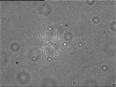
5 between L1 and the mesh reduces the size of the laser beam that is incident on the mesh. The mesh is thus subjected to a convergent beam of light rather than a parallel beam. The second lens, L2, collects the divergent light from the mesh and converts it back into a parallel beam. With reference to Fig. 2a, when the mesh is very close to L1 (~ 1 cm), adjacent traps are separated by 8 μm. When the mesh is 5 cm away from the lens this distance reduces to 6 μm (Fig. 2b). For the separation of 11 cm the distance between the two traps is made as small as 3.4 μm (Fig. 2d). It should be noted that the central spot corresponds to the zeroth order diffraction; the immediately adjacent spots correspond to first order diffraction. If the incident laser power is further increased, second order diffraction spots also become visible. We note that the diffraction efficiency remains constant with distance between the mesh and the objective: as long as all of the individual traps are from the same diffraction order, there is no variation in trap efficiency. In order to demonstrate multiple trapping we carried out eperiments using 1 μm diameter polystyrene spheres suspended in distilled water. The trapping events were captured in a real time movie (see supplementary material) and then converted to snapshots. Figures 3 a-d are typical snapshots showing beads that are trapped at different locations. By increasing the concentration of the beads we were able to demonstrate the trapping of a larger number of beads (Figs. 3 c-d). Now we see trapping at the location of first order diffraction and also at the second order diffraction. The trapped beads could be linearly translated using a precision translation stage, as is seen in the movie clip (see supplementary material). All the available techniques of creating two or more optical traps have some advantages and disadvantages. In case of the acousto-optic deflector (AOD) even though one can control two traps independently, the traps are not continuous, their intermittency depending on the 5
6 frequency of the AOD. Traps using diffractive optical elements have a fied configuration for a static hologram. In order to change the trap configuration one has to change the diffractive optical element. Only in the case of a dynamic hologram can the configuration be easily altered; such traps are fully automated 12,13 but the associated degree of compleity (and cost) is much higher than with the trap described in this work which turns out to be a remarkably simple and inepensive way to manipulate micron size particles. In summary, we have demonstrated a simple technique to generate multiple traps from a single laser beam by using a wire mesh. Multiple trapping of a number of polystyrene beads is shown by way of illustration. There are several attractive features of our proposal: (i) the separation between adjacent trapping centers is easily controlled by changing the position of the mesh; (ii) the diffraction efficiency, hence the trapping efficiency, can be readily enhanced by using a mesh made of thinner wire (thereby increasing the mesh s transmission efficiency); (iii) very high incident laser power can be readily used; and (iv) variability of inter-spot spacing and spot size is readily accessible. JAD thanks the Homi Bhabha Fellowship Council for financial support. 6
7 References 1. A. Ashkin, J. M. Dziedzic, J. E. Bjorkholm, and S. Chu, Opt. Lett. 11, 288 (1986). 2. K. C. Neuman and S. M. Block, Rev. Sci. Instrum. 75, 2787 (2004). 3. K. Visscher, S. P. Gross, and S. Block IEEE J. Sel. Top. Quantum, Electron. 2, 1066 (1996). 4. D. G. Grier and E. R. Dufresne, US patent no B1 (2003). 5. D. G. Grier and E. R. Dufresne, US patent no (2000). 6. J. E. Curtis, B. A. Koss, and D. G. Grier, US patent no B2 (2004). 7. D. G. Grier and E. R. Dufresne, US patent no B1 (2002). 8. H. Schroeder, J. Liu, and S. L. Chin, Opt. Epress 12, 4768 (2004). 9. A. K. Dharmadhikari, F. A. Rajgara, D. Mathur, H. Schroeder, and J. Liu, Opt. Epress 13, 8555 (2005). 10. J. A. Dharmadhikari and D. Mathur, Curr. Sci. 86, 1432 (2004). 11. F. A. Jenkins and H. E. White, Fundamentals of Optics, 3 rd edition (McGraw-Hill, NewYork, 1957) p D. G. Grier and E. R Dufresne, Rev. Sci. Instrum. 69, 8659 (1998). 13. E. R Dufresne, G. C. Spalding, M. T. Dearing, S. A. Sheets, and D. G. Grier, Rev. Sci. Instrum. 72, 1810 (2001). 7
8 Figure Captions 1. Eperimental setup to create multiple traps with a wire mesh (175 μm 175 μm, wire thickness 95 μm) 2. Photographs showing the variation of the distance between adjacent traps accomplished by varying the distance between the wire mesh and the lens L1: a) 1 cm, b) 5 cm, c) 7 cm and d) 11 cm. The corresponding distances between adjacent traps were a) 8 μm, b) 6 μm, c) 5 μm, and d) 3.4 μm. 3. Snapshots showing trapping of 1 μm size polystyrene beads in multiple traps. The distance between the lens and the wire mesh is kept constant at 5 cm. Beads are trapped at different locations: trapping of 3 beads (a) and 4 beads (b) at zeroth and first order diffraction locations, trapping of 5 beads (c) and 6 beads (d) at zeroth, first, and second order diffraction locations. 8
9 Cover slip 100X Wire mesh L2 Laser Beam Epander M1 L1 CCD M2 Fig. 1 9
 5 cm")
 11 cm")
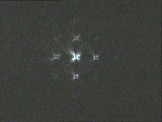
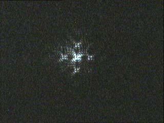
10 a) 1 cm b) 5 cm c) 7 cm d) 11 cm Fig. 2 10
 (d)")
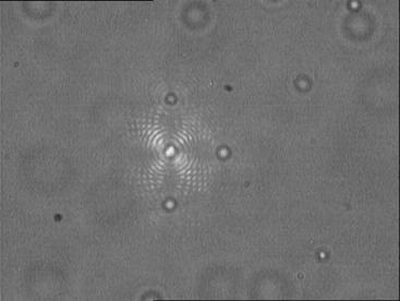
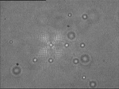
11 (a) (b) (c) (d) Fig. 3 11
Xuechang Ren a *, Canhui Wang, Yanshuang Li, Shaoxin Shen, Shou Liu
 Available online at www.sciencedirect.com Physics Procedia 22 (2011) 493 497 2011 International Conference on Physics Science and Technology (ICPST 2011) Optical Tweezers Array System Based on 2D Photonic
specular diffuse reflection.
 Lesson 8 Light and Optics The Nature of Light Properties of Light: Reflection Refraction Interference Diffraction Polarization Dispersion and Prisms Total Internal Reflection Huygens s Principle The Nature
Diffraction Diffraction occurs when light waves pass through an aperture Huygen's Principal: each point on wavefront acts as source of another wave
 Diffraction Diffraction occurs when light waves pass through an aperture Huygen's Principal: each point on wavefront acts as source of another wave If light coming from infinity point source at infinity
Experiment 8 Wave Optics
 Physics 263 Experiment 8 Wave Optics In this laboratory, we will perform two experiments on wave optics. 1 Double Slit Interference In two-slit interference, light falls on an opaque screen with two closely
OPTICS MIRRORS AND LENSES
 Downloaded from OPTICS MIRRORS AND LENSES 1. An object AB is kept in front of a concave mirror as shown in the figure. (i)complete the ray diagram showing the image formation of the object. (ii) How will
Optical Diffraction and Interference using Single Photon Counting
 Optical Diffraction and Interference using Single Photon Counting Optical Diffraction and Interference using Single Photon Counting In this experiment the wave and quantum properties of light can be studied
Chapter 8: Physical Optics
 Chapter 8: Physical Optics Whether light is a particle or a wave had puzzled physicists for centuries. In this chapter, we only analyze light as a wave using basic optical concepts such as interference
Diffraction: Propagation of wave based on Huygens s principle.
 Diffraction: In addition to interference, waves also exhibit another property diffraction, which is the bending of waves as they pass by some objects or through an aperture. The phenomenon of diffraction
Diffraction at a single slit and double slit Measurement of the diameter of a hair
 Diffraction at a single slit and double slit Measurement of the diameter of a hair AREEJ AL JARB Background... 3 Objects of the experiments 4 Principles Single slit... 4 Double slit.. 6 Setup. 7 Procedure
Physics Midterm I
 Phys121 - February 6, 2009 1 Physics 121 - Midterm I Last Name First Name Student Number Signature Tutorial T.A. (circle one): Ricky Chu Firuz Demir Maysam Emadi Alireza Jojjati Answer ALL 10 questions.
Laser Diffraction and Interference
 Laser Diffraction and Interference Objective 1. To determine the wavelength of laser light from a thin wire diffraction pattern.. Compare the thickness of the wire with the single-slit width that form
Chapter 24. Wave Optics
 Chapter 24 Wave Optics Wave Optics The wave nature of light is needed to explain various phenomena Interference Diffraction Polarization The particle nature of light was the basis for ray (geometric) optics
Waves & Oscillations
 Physics 42200 Waves & Oscillations Lecture 41 Review Spring 2016 Semester Matthew Jones Final Exam Date:Tuesday, May 3 th Time:7:00 to 9:00 pm Room: Phys 112 You can bring one double-sided pages of notes/formulas.
Chapter 24. Wave Optics. Wave Optics. The wave nature of light is needed to explain various phenomena
 Chapter 24 Wave Optics Wave Optics The wave nature of light is needed to explain various phenomena Interference Diffraction Polarization The particle nature of light was the basis for ray (geometric) optics
Optics Vac Work MT 2008
 Optics Vac Work MT 2008 1. Explain what is meant by the Fraunhofer condition for diffraction. [4] An aperture lies in the plane z = 0 and has amplitude transmission function T(y) independent of x. It is
Lecture 4. Physics 1502: Lecture 35 Today s Agenda. Homework 09: Wednesday December 9
 Physics 1502: Lecture 35 Today s Agenda Announcements: Midterm 2: graded soon» solutions Homework 09: Wednesday December 9 Optics Diffraction» Introduction to diffraction» Diffraction from narrow slits»
To determine the wavelength of laser light using single slit diffraction
 9 To determine the wavelength of laser light using single slit diffraction pattern 91 Apparatus: Helium-Neon laser or diode laser, a single slit with adjustable aperture width, optical detector and power
Two slit interference - Prelab questions
 Two slit interference - Prelab questions 1. Show that the intensity distribution given in equation 3 leads to bright and dark fringes at y = mλd/a and y = (m + 1/2) λd/a respectively, where m is an integer.
To see how a sharp edge or an aperture affect light. To analyze single-slit diffraction and calculate the intensity of the light
 Diffraction Goals for lecture To see how a sharp edge or an aperture affect light To analyze single-slit diffraction and calculate the intensity of the light To investigate the effect on light of many
UNIT VI OPTICS ALL THE POSSIBLE FORMULAE
 58 UNIT VI OPTICS ALL THE POSSIBLE FORMULAE Relation between focal length and radius of curvature of a mirror/lens, f = R/2 Mirror formula: Magnification produced by a mirror: m = - = - Snell s law: 1
The location of the bright fringes can be found using the following equation.
 What You Need to Know: In the past two labs we ve been thinking of light as a particle that reflects off of a surface or refracts into a medium. Now we are going to talk about light as a wave. If you take
Physical Optics. You can observe a lot just by watching. Yogi Berra ( )
") Physical Optics You can observe a lot just by watching. Yogi Berra (1925-2015) OBJECTIVES To observe some interference and diffraction phenomena with visible light. THEORY In a previous experiment you
Physical Optics You can observe a lot just by watching. Yogi Berra (1925-2015) OBJECTIVES To observe some interference and diffraction phenomena with visible light. THEORY In a previous experiment you
INTERFERENCE. where, m = 0, 1, 2,... (1.2) otherwise, if it is half integral multiple of wavelength, the interference would be destructive.
 otherwise, if it is half integral multiple of wavelength, the interference would be destructive.") 1.1 INTERFERENCE When two (or more than two) waves of the same frequency travel almost in the same direction and have a phase difference that remains constant with time, the resultant intensity of light
1.1 INTERFERENCE When two (or more than two) waves of the same frequency travel almost in the same direction and have a phase difference that remains constant with time, the resultant intensity of light
Chapter 24. Wave Optics. Wave Optics. The wave nature of light is needed to explain various phenomena
 Chapter 24 Wave Optics Wave Optics The wave nature of light is needed to explain various phenomena Interference Diffraction Polarization The particle nature of light was the basis for ray (geometric) optics
Chapter 37. Wave Optics
 Chapter 37 Wave Optics Wave Optics Wave optics is a study concerned with phenomena that cannot be adequately explained by geometric (ray) optics. Sometimes called physical optics These phenomena include:
Supplementary Figure 1 Optimum transmissive mask design for shaping an incident light to a desired
 Supplementary Figure 1 Optimum transmissive mask design for shaping an incident light to a desired tangential form. (a) The light from the sources and scatterers in the half space (1) passes through the
Chapter 38. Diffraction Patterns and Polarization
 Chapter 38 Diffraction Patterns and Polarization Diffraction Light of wavelength comparable to or larger than the width of a slit spreads out in all forward directions upon passing through the slit This
Unit 5.C Physical Optics Essential Fundamentals of Physical Optics
 Unit 5.C Physical Optics Essential Fundamentals of Physical Optics Early Booklet E.C.: + 1 Unit 5.C Hwk. Pts.: / 25 Unit 5.C Lab Pts.: / 20 Late, Incomplete, No Work, No Units Fees? Y / N 1. Light reflects
Waves & Oscillations
 Physics 42200 Waves & Oscillations Lecture 42 Review Spring 2013 Semester Matthew Jones Final Exam Date:Tuesday, April 30 th Time:1:00 to 3:00 pm Room: Phys 112 You can bring two double-sided pages of
5. Double Slit Diffraction
 Double Date slit : diffraction 5. Double Slit Diffraction Background Aim of the experiment Huygens s principle Interference Fraunhofer and Fresnel diffraction Coherence Laser 1. To plot the intensity distribution
Chapter 37. Interference of Light Waves
 Chapter 37 Interference of Light Waves Wave Optics Wave optics is a study concerned with phenomena that cannot be adequately explained by geometric (ray) optics These phenomena include: Interference Diffraction
Optics Final Exam Name
 Instructions: Place your name on all of the pages. Do all of your work in this booklet. Do not tear off any sheets. Show all of your steps in the problems for full credit. Be clear and neat in your work.
Physics 1C, Summer 2011 (Session 1) Practice Midterm 2 (50+4 points) Solutions
 Practice Midterm 2 (50+4 points) Solutions") Physics 1C, Summer 2011 (Session 1) Practice Midterm 2 (50+4 points) s Problem 1 (5x2 = 10 points) Label the following statements as True or False, with a one- or two-sentence explanation for why you chose
Physics 1C, Summer 2011 (Session 1) Practice Midterm 2 (50+4 points) s Problem 1 (5x2 = 10 points) Label the following statements as True or False, with a one- or two-sentence explanation for why you chose
Diffraction Diffraction occurs when light waves is passed by an aperture/edge Huygen's Principal: each point on wavefront acts as source of another
 Diffraction Diffraction occurs when light waves is passed by an aperture/edge Huygen's Principal: each point on wavefront acts as source of another circular wave Consider light from point source at infinity
Chapter 24. Wave Optics
 Chapter 24 Wave Optics Diffraction Huygen s principle requires that the waves spread out after they pass through slits This spreading out of light from its initial line of travel is called diffraction
Ray Optics I. Last time, finished EM theory Looked at complex boundary problems TIR: Snell s law complex Metal mirrors: index complex
 Phys 531 Lecture 8 20 September 2005 Ray Optics I Last time, finished EM theory Looked at complex boundary problems TIR: Snell s law complex Metal mirrors: index complex Today shift gears, start applying
Single Photon Interference
 December 19, 2006 D. Lancia P. McCarthy Classical Interference Intensity Distribution Overview Quantum Mechanical Interference Probability Distribution Which Path? The Effects of Making a Measurement Wave-Particle
Spectrographs. C. A. Griffith, Class Notes, PTYS 521, 2016 Not for distribution.
 Spectrographs C A Griffith, Class Notes, PTYS 521, 2016 Not for distribution 1 Spectrographs and their characteristics A spectrograph is an instrument that disperses light into a frequency spectrum, which
FRAUNHOFFER DIFFRACTION AT SINGLE SLIT
 15 Experiment-37 F FRAUNHOFFER DIFFRACTION AT SINGLE SLIT Sarmistha Sahu Head Dept of Physics, Maharani Laxmi Ammani College For Women BANGALORE- 560 012. INDIA Email: sarmis@eth.net. Abstract Fraunhoffer
Single Photon Interference Christopher Marsh Jaime Vela
 Single Photon Interference Christopher Marsh Jaime Vela Abstract The purpose of this experiment was to study the dual wave-particle nature of light. Using a Mach-Zehnder and double slit interferometer,
Models of Light The wave model: The ray model: The photon model:
 Models of Light The wave model: under many circumstances, light exhibits the same behavior as sound or water waves. The study of light as a wave is called wave optics. The ray model: The properties of
2011 Optical Science & Engineering PhD Qualifying Examination Optical Sciences Track: Advanced Optics Time allowed: 90 minutes
 2011 Optical Science & Engineering PhD Qualifying Examination Optical Sciences Track: Advanced Optics Time allowed: 90 minutes Answer all four questions. All questions count equally. 3(a) A linearly polarized
Diffraction and Interference of Plane Light Waves
 1 Diffraction and Interference of Plane Light Waves Introduction In this experiment you will become familiar with diffraction patterns created when a beam of light scatters from objects placed in its path.
Introduction. Part I: Measuring the Wavelength of Light. Experiment 8: Wave Optics. Physics 11B
 Physics 11B Experiment 8: Wave Optics Introduction Equipment: In Part I you use a machinist rule, a laser, and a lab clamp on a stand to hold the laser at a grazing angle to the bench top. In Part II you
Diffraction and Interference of Plane Light Waves
 PHY 92 Diffraction and Interference of Plane Light Waves Diffraction and Interference of Plane Light Waves Introduction In this experiment you will become familiar with diffraction patterns created when
OPSE FINAL EXAM Fall CLOSED BOOK. Two pages (front/back of both pages) of equations are allowed.
 of equations are allowed.") CLOSED BOOK. Two pages (front/back of both pages) of equations are allowed. YOU MUST SHOW YOUR WORK. ANSWERS THAT ARE NOT JUSTIFIED WILL BE GIVEN ZERO CREDIT. ALL NUMERICAL ANSERS MUST HAVE UNITS INDICATED.
CLOSED BOOK. Two pages (front/back of both pages) of equations are allowed. YOU MUST SHOW YOUR WORK. ANSWERS THAT ARE NOT JUSTIFIED WILL BE GIVEN ZERO CREDIT. ALL NUMERICAL ANSERS MUST HAVE UNITS INDICATED.
E x Direction of Propagation. y B y
 x E x Direction of Propagation k z z y B y An electromagnetic wave is a travelling wave which has time varying electric and magnetic fields which are perpendicular to each other and the direction of propagation,
PHY 222 Lab 11 Interference and Diffraction Patterns Investigating interference and diffraction of light waves
 PHY 222 Lab 11 Interference and Diffraction Patterns Investigating interference and diffraction of light waves Print Your Name Print Your Partners' Names Instructions April 17, 2015 Before lab, read the
Midterm II Physics 9B Summer 2002 Session I
 Midterm II Physics 9B Summer 00 Session I Name: Last 4 digits of ID: Total Score: ) Two converging lenses, L and L, are placed on an optical bench, 6 cm apart. L has a 0 cm focal length and is placed to
Diffraction. Introduction: Diffraction is bending of waves around an obstacle (barrier) or spreading of waves passing through a narrow slit.
 or spreading of waves passing through a narrow slit.") Introduction: Diffraction is bending of waves around an obstacle (barrier) or spreading of waves passing through a narrow slit. Diffraction amount depends on λ/a proportion If a >> λ diffraction is negligible
Introduction: Diffraction is bending of waves around an obstacle (barrier) or spreading of waves passing through a narrow slit. Diffraction amount depends on λ/a proportion If a >> λ diffraction is negligible
Chapter 36. Diffraction. Dr. Armen Kocharian
 Chapter 36 Diffraction Dr. Armen Kocharian Diffraction Light of wavelength comparable to or larger than the width of a slit spreads out in all forward directions upon passing through the slit This phenomena
Unit-22 Interference and Diffraction
 Unit-22 Interference and iffraction Objective: In this experiment, we used single-slit, double-slit, circular hole and grating to measure the wavelength of laser. Apparatus: Optical track, diode laser,
ConcepTest PowerPoints
 ConcepTest PowerPoints Chapter 24 Physics: Principles with Applications, 6 th edition Giancoli 2005 Pearson Prentice Hall This work is protected by United States copyright laws and is provided solely for
PHYSICS. Chapter 33 Lecture FOR SCIENTISTS AND ENGINEERS A STRATEGIC APPROACH 4/E RANDALL D. KNIGHT
 PHYSICS FOR SCIENTISTS AND ENGINEERS A STRATEGIC APPROACH 4/E Chapter 33 Lecture RANDALL D. KNIGHT Chapter 33 Wave Optics IN THIS CHAPTER, you will learn about and apply the wave model of light. Slide
Chapter 36. Diffraction. Copyright 2014 John Wiley & Sons, Inc. All rights reserved.
 Chapter 36 Diffraction Copyright 36-1 Single-Slit Diffraction Learning Objectives 36.01 Describe the diffraction of light waves by a narrow opening and an edge, and also describe the resulting interference
DIFFRACTION 4.1 DIFFRACTION Difference between Interference and Diffraction Classification Of Diffraction Phenomena
 4.1 DIFFRACTION Suppose a light wave incident on a slit AB of sufficient width b, as shown in Figure 1. According to concept of rectilinear propagation of light the region A B on the screen should be uniformly
Module 18: Diffraction-I Lecture 18: Diffraction-I
 Module 18: iffraction-i Lecture 18: iffraction-i Our discussion of interference in the previous chapter considered the superposition of two waves. The discussion can be generalized to a situation where
Diffraction and Interference
 Experiment #32 Diffraction and Interference Goals: Perform a quantitative investigation of two-slit interference Explore use of a photodiode to measure light intensity References 1. I. G. Main, Vibrations
Downloaded from UNIT 06 Optics
 1 Mark UNIT 06 Optics Q1: A partially plane polarised beam of light is passed through a polaroid. Show graphically the variation of the transmitted light intensity with angle of rotation of the Polaroid.
TEAMS National Competition High School Version Photometry 25 Questions
 TEAMS National Competition High School Version Photometry 25 Questions Page 1 of 14 Telescopes and their Lenses Although telescopes provide us with the extraordinary power to see objects miles away, the
COHERENCE AND INTERFERENCE
 COHERENCE AND INTERFERENCE - An interference experiment makes use of coherent waves. The phase shift (Δφ tot ) between the two coherent waves that interfere at any point of screen (where one observes the
Diffraction and Interference Lab 7 PRECAUTION
 HB 11-14-07 Diffraction and Interference Lab 7 1 Diffraction and Interference Lab 7 Equipment laser, eye goggles, optical bench, slide holder, slide with 4 single slits, slide with 4 double slits, 11X14
Review Session 1. Dr. Flera Rizatdinova
 Review Session 1 Dr. Flera Rizatdinova Summary of Chapter 23 Index of refraction: Angle of reflection equals angle of incidence Plane mirror: image is virtual, upright, and the same size as the object
Wave Particle Duality with Single Photon Interference
 Wave Particle Duality with Single Photon Interference Gerardo I. Viza 1, 1 Department of Physics and Astronomy, University of Rochester, Rochester, NY 14627 In the experiments of the Mach-Zehnder Interferometer
Chapter 38 Wave Optics (II)
") Chapter 38 Wave Optics (II) Initiation: Young s ideas on light were daring and imaginative, but he did not provide rigorous mathematical theory and, more importantly, he is arrogant. Progress: Fresnel,
Chapter 38 Wave Optics (II) Initiation: Young s ideas on light were daring and imaginative, but he did not provide rigorous mathematical theory and, more importantly, he is arrogant. Progress: Fresnel,
1 Laboratory #4: Division-of-Wavefront Interference
 1051-455-0073, Physical Optics 1 Laboratory #4: Division-of-Wavefront Interference 1.1 Theory Recent labs on optical imaging systems have used the concept of light as a ray in goemetrical optics to model
Waves & Oscillations
 Physics 42200 Waves & Oscillations Lecture 37 Interference Spring 2016 Semester Matthew Jones Multiple Beam Interference In many situations, a coherent beam can interfere with itself multiple times Consider
TEAMS National Competition Middle School Version Photometry 25 Questions
 TEAMS National Competition Middle School Version Photometry 25 Questions Page 1 of 13 Telescopes and their Lenses Although telescopes provide us with the extraordinary power to see objects miles away,
Chapter 35 &36 Physical Optics
 Chapter 35 &36 Physical Optics Physical Optics Phase Difference & Coherence Thin Film Interference 2-Slit Interference Single Slit Interference Diffraction Patterns Diffraction Grating Diffraction & Resolution
EELE 482 Lab #3. Lab #3. Diffraction. 1. Pre-Lab Activity Introduction Diffraction Grating Measure the Width of Your Hair 5
 Lab #3 Diffraction Contents: 1. Pre-Lab Activit 2 2. Introduction 2 3. Diffraction Grating 4 4. Measure the Width of Your Hair 5 5. Focusing with a lens 6 6. Fresnel Lens 7 Diffraction Page 1 (last changed
Chapter 24 - The Wave Nature of Light
 Chapter 24 - The Wave Nature of Light Summary Four Consequences of the Wave nature of Light: Diffraction Dispersion Interference Polarization Huygens principle: every point on a wavefront is a source of
Electricity & Optics
 Physics 24100 Electricity & Optics Lecture 27 Chapter 33 sec. 7-8 Fall 2017 Semester Professor Koltick Clicker Question Bright light of wavelength 585 nm is incident perpendicularly on a soap film (n =
Intermediate Physics PHYS102
 Intermediate Physics PHYS102 Dr Richard H. Cyburt Assistant Professor of Physics My office: 402c in the Science Building My phone: (304) 384-6006 My email: rcyburt@concord.edu My webpage: www.concord.edu/rcyburt
Lab2: Single Photon Interference
 Lab2: Single Photon Interference Xiaoshu Chen* Department of Mechanical Engineering, University of Rochester, NY, 14623 ABSTRACT The wave-particle duality of light was verified by multi and single photon
LIGHT SCATTERING THEORY
 LIGHT SCATTERING THEORY Laser Diffraction (Static Light Scattering) When a Light beam Strikes a Particle Some of the light is: Diffracted Reflected Refracted Absorbed and Reradiated Reflected Refracted
Textbook Reference: Physics (Wilson, Buffa, Lou): Chapter 24
: Chapter 24") AP Physics-B Physical Optics Introduction: We have seen that the reflection and refraction of light can be understood in terms of both rays and wave fronts of light. Light rays are quite compatible with
AP Physics-B Physical Optics Introduction: We have seen that the reflection and refraction of light can be understood in terms of both rays and wave fronts of light. Light rays are quite compatible with
Chapter 24. Wave Optics
 Chapter 24 Wave Optics hitt1 An upright object is located a distance from a convex mirror that is less than the mirror's focal length. The image formed by the mirror is (1) virtual, upright, and larger
Where n = 0, 1, 2, 3, 4
 Syllabus: Interference and diffraction introduction interference in thin film by reflection Newton s rings Fraunhofer diffraction due to single slit, double slit and diffraction grating Interference 1.
(Refer Slide Time: 00:10)
") Fundamentals of optical and scanning electron microscopy Dr. S. Sankaran Department of Metallurgical and Materials Engineering Indian Institute of Technology, Madras Module 02 Unit-4 Phase contrast, Polarized
Fundamentals of optical and scanning electron microscopy Dr. S. Sankaran Department of Metallurgical and Materials Engineering Indian Institute of Technology, Madras Module 02 Unit-4 Phase contrast, Polarized
Analysis of Cornell Electron-Positron Storage Ring Test Accelerator's Double Slit Visual Beam Size Monitor
 Analysis of Cornell Electron-Positron Storage Ring Test Accelerator's Double Slit Visual Beam Size Monitor Senior Project Department of Physics California Polytechnic State University San Luis Obispo By:
10.5 Polarization of Light
 10.5 Polarization of Light Electromagnetic waves have electric and magnetic fields that are perpendicular to each other and to the direction of propagation. These fields can take many different directions
Physics 214 Midterm Fall 2003 Form A
 1. A ray of light is incident at the center of the flat circular surface of a hemispherical glass object as shown in the figure. The refracted ray A. emerges from the glass bent at an angle θ 2 with respect
About the Final Exam(1)
") About the Final Exam(1) The exam will be on 7:45-9:45am, Wednesday, Dec 22 in: 2103 Chamberlin, and 810 Ingraham (Allocation to be announced) It will be exactly 120 minutes. Distribution of tests starts
About the Final Exam(1) The exam will be on 7:45-9:45am, Wednesday, Dec 22 in: 2103 Chamberlin, and 810 Ingraham (Allocation to be announced) It will be exactly 120 minutes. Distribution of tests starts
Wave Optics. April 11, 2014 Chapter 34 1
 Wave Optics April 11, 2014 Chapter 34 1 Announcements! Exam tomorrow! We/Thu: Relativity! Last week: Review of entire course, no exam! Final exam Wednesday, April 30, 8-10 PM Location: WH B115 (Wells Hall)
Optical Trapping in the Teaching Lab
 BE.309: Biological Instrumentation and Measurement Laboratory GEM4 Summer School Optical Trapping in the Teaching Lab 1 Lab Objective 1. Become familiar with the fundamentals of optical trapping. 2. Learn
Basic optics. Geometrical optics and images Interference Diffraction Diffraction integral. we use simple models that say a lot! more rigorous approach
 Basic optics Geometrical optics and images Interference Diffraction Diffraction integral we use simple models that say a lot! more rigorous approach Basic optics Geometrical optics and images Interference
Chapter 25. Wave Optics
 Chapter 25 Wave Optics Interference Light waves interfere with each other much like mechanical waves do All interference associated with light waves arises when the electromagnetic fields that constitute
Near Field Observation of a Refractive Index Grating and a Topographical Grating by an Optically Trapped Gold Particle
 Near Field Observation of a Refractive Index Grating and a Topographical Grating by an Optically Trapped Gold Particle Hiroo UKITA and Hirotaka UEMI Ritsumeikan University, Kusatsu-shi, Shiga, 2 Japan
Light & Optical Systems Reflection & Refraction. Notes
 Light & Optical Systems Reflection & Refraction Notes What is light? Light is electromagnetic radiation Ultra-violet + visible + infra-red Behavior of Light Light behaves in 2 ways particles (photons)
MICHELSON S INTERFEROMETER
 MICHELSON S INTERFEROMETER Objectives: 1. Alignment of Michelson s Interferometer using He-Ne laser to observe concentric circular fringes 2. Measurement of the wavelength of He-Ne Laser and Na lamp using
Wave Phenomena Physics 15c. Lecture 19 Diffraction
 Wave Phenomena Physics 15c Lecture 19 Diffraction What We Did Last Time Studied interference > waves overlap Amplitudes add up Intensity = (amplitude) does not add up Thin-film interference Reflectivity
About the Final Exam(1)
") About the Final Exam(1) The exam will be on 2:45-4:45pm, Wednesday, Dec 19 th (See my earlier email for room allocation) It will be exactly 120 minutes. Four (3+1) 8½ x 11 formula sheets are allowed. Must
About the Final Exam(1) The exam will be on 2:45-4:45pm, Wednesday, Dec 19 th (See my earlier email for room allocation) It will be exactly 120 minutes. Four (3+1) 8½ x 11 formula sheets are allowed. Must
Selective Optical Assembly of Highly Uniform. Nanoparticles by Doughnut-Shaped Beams
 SUPPLEMENTARY INFORMATION Selective Optical Assembly of Highly Uniform Nanoparticles by Doughnut-Shaped Beams Syoji Ito 1,2,3*, Hiroaki Yamauchi 1,2, Mamoru Tamura 4,5, Shimpei Hidaka 4,5, Hironori Hattori
Chapter 2: Wave Optics
 Chapter : Wave Optics P-1. We can write a plane wave with the z axis taken in the direction of the wave vector k as u(,) r t Acos tkzarg( A) As c /, T 1/ and k / we can rewrite the plane wave as t z u(,)
PHYS 3410/3411/6750/6751: Modern Optics Midterm #2
 Name: PHYS 3410/3411/6750/6751: Modern Optics Midterm #2 Wednesday 17 November 2010 Prof. Bolton Only pen or pencil are allowed. No calculators or additional materials. PHYS 3410/3411/6750/6751 Midterm
Chapter 24. Wave Optics
 Chapter 24 Wave Optics Wave Optics The wave nature of light is needed to explain various phenomena Interference Diffraction Polarization The particle nature of light was the basis for ray (geometric) optics
Figure 1: Derivation of Bragg s Law
 What is Bragg s Law and why is it Important? Bragg s law refers to a simple equation derived by English physicists Sir W. H. Bragg and his son Sir W. L. Bragg in 1913. This equation explains why the faces
PHYS 3410/6750: Modern Optics Midterm #2
 Name: PHYS 3410/6750: Modern Optics Midterm #2 Wednesday 16 November 2011 Prof. Bolton Only pen or pencil are allowed. No calculators or additional materials. PHYS 3410/6750 Fall 2011 Midterm #2 2 Problem
Interference of Light
 Lecture 23 Chapter 22 Physics II 08.07.2015 Wave Optics: Interference of Light Course website: http://faculty.uml.edu/andriy_danylov/teaching/physicsii Lecture Capture: http://echo360.uml.edu/danylov201415/physics2spring.html
Chapter 24 The Wave Nature of Light
 Chapter 24 The Wave Nature of Light 24.1 Waves Versus Particles; Huygens Principle and Diffraction Huygens principle: Every point on a wave front acts as a point source; the wavefront as it develops is