Manipulator Path Control : Path Planning, Dynamic Trajectory and Control Analysis
|
|
|
- Shannon Wilcox
- 6 years ago
- Views:
Transcription
1 Manipulator Path Control : Path Planning, Dynamic Trajectory and Control Analysis Motion planning for industrial manipulators is a challenging task when obstacles are present in the workspace so that collision-free paths must be found. However, not all paths are suitable for optimal task performance in terms of execution time or energetic cost. Trajectory generation schemes must therefore consider the system dynamics in order to find admissible solutions along a desired path subject to a cost function.
2 APPLICATION: ASSEMBLY COATING APPLICATIONS. CONVEYOR PALLET TRANSFER. DIE CASTING. FOUNDARY AND FORGING APPLICATIONS. INSPECTION MOULDING. CASTING. MACHINE LOADING AND UNLOADING.
3 CLASSIFICATION: CLASSIFIED INTO SIX CATEGORIES ARM GEOMETRY (robot arm anatomy): RECTANGULAR;CYLINDIRICAL;SPHERICAL; JOINTED- ARM(VERTICAL);JOINED-ARM(HORIZONTAL). DEGREES OF FREEDOM: ROBOT ARM; ROBOT WRIST. POWER SOURCES: ELECTRICAL;PNEUMATIC;HYDRAULIC;ANY COMBINATION. TYPE OF MOTION: SLEW MOTION; JOINT- INTERPOLATION; STRAIGHT-LINE INTERPOLATION; CIRCULAR INTERPOLATION. PATH CONTROL: LIMITED SEQUENCE; POINT-TO-POINT; CONTINOUS PATH; CONTROLLED PATH. INTELLLIGENCE LEVEL: LOW-TECHNOLOGY(NONSERVO); HIGH-TECHONOLOGY(SERVO).
4 ARM GEOMETRY ROBOT MUST BE ABLE TO REACH A POINT IN SPACE WITHIN THREE AXES (X,Y Z) BY MOVING FORWARD AND BACKWARD, TO THE LEFT AND RIGHT, AND UP AND DOWN. ROBOT MANIPULATOR MAY BE CLASSIFIED ACCORDING TO THE TYPE OF MOVEMENT NEEDED TO COMPLETE THE TASK. RECTANGULAR-COORDINATED: - HAS THREE LINEAR AXES OF MOTION. - X REPRESENTS LEFT AND RIGHT MOTION - Y DESCRIBES FORWARD AND BACKWARD MOTION. - Z IS USED TO DEPICT UP-AND-DOWN MOTION. THE WORK ENVELOPE OF A RECTANGULAR ROBOT IS A CUBE OR RECTANGLE, SO THAT ANY WORK PERFORMED BY ROBOT MUST ONLY INVOLVE MOTIONS INSIDE THE SPACE.
5
6 RECTANGULAR COORDINATES ADVANTAGES: THEY CAN OBTAIN LARGE WORK ENVELOPE BECAUSE TRAVELLING ALONG THE X-AXIS, THE VOLUME REGION CAN BE INCREASED EASILY. THEIR LINEAR MOVEMENT ALLOWS FOR SIMPLER CONTROLS. THEY HAVE HIGH DEGREE OF MECHANICAL RIGIDITY, ACCURACY, AND REPEATABILITY DUE O THEIR STRUCTURE. THEY CAN CARRY HEAVY LOADS BECAUSE THE WEIGHT-LIFTING CAPACITY DOES NOT VARY AT DIFFERENT LOCATIONS WITHING THE WORK ENVELOPE. DISADVANTAGES: THEY MAKES MAINTENANCE MORE DIFFICULT FOR SOME MODELS WITH OVERHEAD DRIVE MECHANISMS AND CONTROL EQUIPMENT. ACCESS TO THE VOLUME REGION BY OVERHEAD CRANE OR OTHER MATERIAL-HANDLING EQUIPMENT MAY BE IMPAIRED BY THE ROBOT- SUPPORTING STRUCTURE. THEIR MOVEMENT IS LIMITED TO ONE DIRECTION AT A TIME.
7 RECTANGULAR COORDINATES APPLICATION: PICK-AND-PLACE OPERATIONS. ADHESIVE APPLICATIONS(MOSTLY LONG AND STRAIGHT). ADVANCED MUNITION HANDLING. ASSEMBLY AND SUBASSEMBLY(MOSTLY STRAIGHT). AUTOMATED LOADING CNC LATHE AND MILLING OPERATIONS. NUCLEAR MATERIAL HANDLING. WELDING.
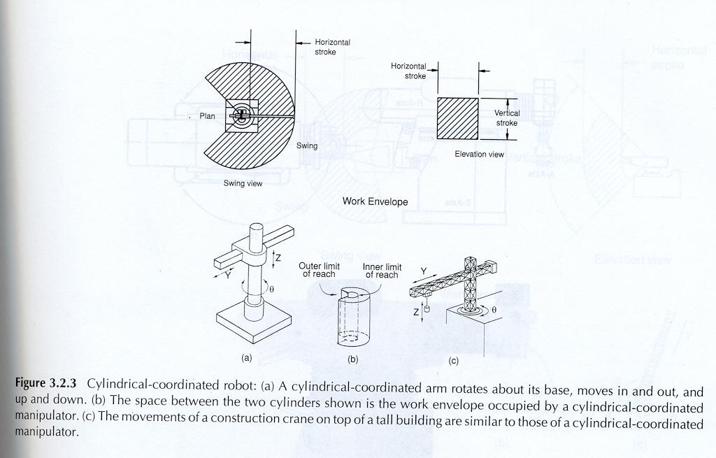
8 CYLINDRICAL-COORDINATED HAS TWO LINEAR MOTIONS AND ONE ROTARY MOTION. ROBOTS CAN ACHIEVE VARIABLE MOTION. THE FIRST COORDINATE DESCRIBE THE ANGLE THETA OF BASE ROTATION--- ABOUT THE UP-DOWN AXIS. THE SECOND COORDINATE CORRESPOND TO A RADICAL OR Y --- IN OUT MOTION AT WHATEVER ANGLE THE ROBOT IS POSITIONED. THE FINAL COORDINATE AGAIN CORRESPONDS TO THE UP -DOWN Z POSITION. ROTATIONAL ABILITY GIVES THE ADVANTAGE OF MOVING RAPIDLY TO THE POINT IN Z PLANE OF ROTATION. RESULTS IN A LARGER WORK ENVELOPE THAN A RECTANGULAR ROBOT MANIPULATOR. SUITED FOR PICK-AND-PLACE OPERATIONS.
9
10 ADVANTAGE: THEIR VERTICAL STRUCTURE CONSERVES FLOOR SPACE. THEIR DEEP HORIZONTAL REACH IS USEFUL FOR FAR-REACHING OPERATIONS. THEIR CAPACITY IS CAPABLE OF CARRYING LARGE PAYLOADS. DISADVANTAGE: THEIR OVERALL MECHANICAL RIGIDITY IS LOWER THAN THAT OF THE RECTILINEAR ROBOTS BECAUSE THEIR ROTARY AXIS MUST OVERCOME INERTIA. THEIR REPEATABILITY AND ACCURACY ARE ALSO LOWER IN THE DIRECTION OF ROTARY MOTION. THEIR CONFIGURATION REQUIRES A MORE SOPHISTICATED CONTROL SYSTEM THAN THE RECTANGULAR ROBOTS.
11 SPHERICAL COORDINATED HAS ONE LINEAR MOTION AND TWO ROTARY MOTIONS. THE WORK VOLUME IS LIKE A SECTION OF SPHERE. THE FIRST MOTION CORRESPONDS TO A BASE ROTATION ABOUT A VERTICAL AXIS. THE SECOND MOTION CORRESPONDS TO AN ELBOW ROTATION. THE THIRD MOTION CORRESPONDS TO A RADIAL (PRISMATIC), OR IN-OUT, TRANSLATION. A SPHERICAL-COORDINATED ROBOTS PROVIDES A LARGER WORK ENVELOPE THAN THE RECTILINEAR OR CYLINDIRICAL ROBOT. DESIGN GIVES WEIGHT LIFTING CAPABILITIES. ADVANTAGES AND DISADVANTAGES SAME AS CYLINDIRICAL-COORDINATED DESIGN.
12
13 APPLICATIONS: DIE CASTING DIP COATING FORGING GLASS HANDLING HEAT TREATING INJECTION MOLDING MACHINE TOOL HANDLING MATERIAL TRANSFER PARTS CLEANING PRESS LOADING STACKING AND UNSTICKING.
14 DEGREES OF FREEDOM THE DEGREE OF FREEDOM OR GRIP OF A ROBOTIC SYSTEM CAN BE COMPARED TO THE WAY IN WHICH THE HUMAN BODY MOVES. FOR EACH DEGREE OF FREEDOM A JOINT IS REQUIRED. THE DEGREES OF FREEDOM LOCATED IN THE ARM DEFINE THE CONFIGURATION. THREE DEGREES OF FREEDOM LOCATED IN THE WRIST GIVE THE END EFFECTOR ALL THE FLEXIBILITY. PITCH OR BEND: IS THE UP-AND-DOWN MOVEMENT OF THE WRIST. YAW: IS THE RIGHT-AND-LEFT MOVEMENT OF THE WRIST. ROLL OR SWIVEL: IS THE ROTATION OF THE HAND. THE MORE THE DEGREES OF FREEDOM, THE GREATER IS THE COMPLEXITY OF MOTIONS ENCOUNTERED.
15
16 POWER SOURCES THE (4) POWER SOURCES USED IN CURRENT ROBOTS ARE: ELECTRIC AND ELECTRO-MECHANICAL: ALL ROBOTS USE ELECTRICITY AS THE PRIMARY SOURCE OF ENERGY. ELECTRICITY TURNS THE PUMPS THAT PROVIDE HYDRAULLIC AND PNEUMATIC PRESSURE. IT ALSO POWERS THE ROBOT CONTROLLER AND ALL THE ELECTRONIC COMPONENTS AND PERIPHERAL DEVICES. IN ALL ELECTRIC ROBOTS, THE DRIVE ACTUATORS, AS WELL AS THE CONTROLLER, ARE ELECTRICALLY POWERED. BECAUSE ELECTRIC ROBOT DO NOT REQUIRE A HYDRAULIC POWER UNIT, THEY CONSERVE FLOOR SPACE AND DECREASE FACTORY NOISE. - affordable, small and simple Direct-Current (DC) Motors: speed of the motor controlled by the input voltage ServoMotors: position controlled (-180 ~ 180 )
17 PNEUMATIC: THESE ARE GENERALLY FOUND IN RELATIVELY LOW-COST MANIPULATORS WITH LOW LOAD CARRYING CAPACITY. PNEUMATIC DRIVES HAVE BEEN USED FOR MANY YEARS FOR POWERING SIMPLE STOP-TO-STOP MOTIONS. IT IS INHERENTLY LIGHT WEIGHT, PARTICULARLY WHEN OPERATING PRESSURES ARE MODERATE.
18 HYDRAULIC: ARE EITHER LINEAR POSITION ACTUATORS OR A ROTARY CONFIGURATION. HYDRAULIC ACTUATORS PROVIDE A LARGE AMOUNT OF POWER FOR A GIVEN ACTUATOR. THE HIGH POWER-TO-WEIGHT RATIO MAKES THE HYDRAULIC ACTUATOR AN ATTRACTIVE CHOICE FOR MOVING MODERATE TO HIGH LOADS AT REASONABLE SPEEDS AND MODERATE NOISE LEVEL. HYDRAULIC MOTORS USUALLY PROVIDE A MORE EFFICIENT WAY OF ENERGY TO ACHIEVE A BETTER PERFORMANCE, BUT THEY ARE EXPENSIVE AND GENERALLY LESS ACCURATE.
19 Joint Space Trajectories For a robot to operate efficiently it must be able to move from point to point in space. A trajectory is a time history of position, velocity and acceleration for each joint. Trajectories are computed at run time and updated at a certain rate - the Path Update Rate.
 Choice of two trajectories to get there.")
20 Joint Space Trajectory Planning (θ 0, t 0 ) A Consider a robot with only one link. Kinematics gives one configuration for B. B (θ f, t f ) Choice of two trajectories to get there. May wish to specify a via point - maybe to avoid an obstacle.

 angle θ f θ 0 0 t f Lots of choices")
21 Joint Space Schemes. We need to describe path shapes in terms of functions of joint angles. θ(t) angle θ f θ 0 0 t f Lots of choices for continuous functions time
22 Manipulator path control is controlling the path followed by the arm traveling from one point to another in the workspace. Interpolation Definition: is a means of determining the value of an unknown data point based on the values of known surrounding data points.
23 TYPES OF ROBOT MANIPULATOR MOTION A ROBOT MANIPULATOR CAN MAKE FOUR TYPES OF MOTION IN TRAVELLING FROM ONE POINT TO ANOTHER IN THE WORKPLACE: SLEW MOTION : SIMPLEST TYPE OF MOTION. ROBOT IS COMMANDED TO TRAVEL FROM ONE POINT TO ANOTHER AT DEFAULT SPEED. Performs without any calculations so it often leads to unanticipated results and wear on the robot joints JOINT-INTERPOLATED MOTION: REQUIRES THE ROBOT CONTROLLER TO CALCULATE THE TIME IT WILL TAKE EACH JOINT TO REACH ITS DESTINATION AT THE COMMANDED SPEED. Calculates (using controller) the amount of time it will take each joint to reach its destination at the commanded speed. It then selects the maximum time among these and uses this value as the time for each axis. This means that a separate velocity is calculated for each axis. An advantage is that the robot joints move at a calculated speed, causes less stress on the joints and path can be repeated because it is predictable. All joints move at same time.
24 Joint Interpolated Motion is the dominant type of joint motion when moving the robot in forward kinematics. Typically, the robot is commanded to move from the current configuration to a new set of joint values. Obviously, there are numerous ways the robot controller could choose to make the change. For example, the robot controller could choose to move joint one to its new value, then joint 2, etc., until all the joints have been moved to their new values, but this would take more time than necessary. For this reason, joint interpolated motion is the algorithm of choice.
25 The joint interpolated algorithm 1. examines each joint for the changes in joint angles, 2. estimates the time to accomplish each joint change at the current speed setting, given the speed allowables for each joint, 3. determines the joint which will take the longest time to accomplish the joint change, 4. then slows
26 TYPES OF MOTION CONT- STRAIGHT-LINE INTERPOLATION MOTION: REQUIRES THE END OF THE END EFFECTOR TO TRAVEL ALONG A STRAIGHT PATH DETERMINE IN RECTANGULAR XYCOORDINATES. USEFUL IN APPLICATIONS SUCH AS ARC WELDING, INSERTING PINS INTO HOLES, OR LAYING MATERIAL ALONG A STRAIGHT PATH. Most demanding for the controller because the transformations must be computed. CIRCULAR INTERPOLATION MOTION: REQUIRES THE ROBOT CONTROLLER TO DEFINE THE POINTS OF A CIRCLE IN THE WORKPLACE BASED ON A MINIMUM OF THREE SPECIFIED POSITIONS. CIRCULAR INTERPOLATION PRODUCES A LINEAR APPROXIMATION OF THE CIRCLE AND IS MORE READILY AVAILABLE USING A PROGRAMMING LANGUAGE RATHER THAN MANUAL OR TEACH PENDANT TECHNIQUES.
27 PATH CONTROL COMMERCIALLY AVAILABLE INDUSTRIAL ROBOTS CAN BE CLASSIFIED INTO FOUR CATEGORIES ACCORDING TO THE PATH CONTROL SYSTEM. LIMITED-SEQUENCE: DO NOT USE SERVO-CONTROL TO INDICATE RELATIVE POSITIONS OF THE JOINTS. THEY ARE CONTROLLED BY SETTING LIMIT SWITCHES AND/OR MECHANICAL STOPS TOGETHER WITH A SEQUENCER TO COORDINATE AND TIME THE ACTUATION OF THE JOINTS. WITH THIS METHOD OF CONTROL, THE INDIVDUAL JOINTS CAN ONLY BE MOVED TO THEIR EXTREME LIMITS OF TRAVEL. POINT-TO-POINT: THESE ROBOTS ARE MOST COMMON AND CAN MOVE FROM ONE SPECIFIED POINT TO ANOTHER BUT CANNOT STOP AT ARBITRARY POINTS NOT PREVIOUSLY DESIGNATED. Robots programmed and controlled in this manner are programmed to move from one discrete point to another within the robot's working envelope. In the automatic mode of operation, the exact path taken by the robot will vary slightly due to variations in velocity, joint geometries, and point spatial locations. This difference in paths is difficult to predict and therefore can create a potential safety hazard to personnel and equipment.
28 CONTROLLED PATH: IS A SPECIALIZED CONTROL METHOD THAT IS A PART OF GENERAL CATEGORY OF A POINT-TO-POINT ROBOT BUT WITH MORE PRECISE CONTROL. THE CONTROLLED PATH ROBOT ENSURES THAT THE ROBOT WILL DESCRIBE THE RIGHT SEGMENT BETWEEN TWO TAUGHT POINTS. CONTROLLED-PATH IS A CALCULATED METHOD AND IS DESIRED WHEN THE MANIPULATOR MUST MOVE IN THE PERFECT PATH MOTION. This mode of movement ensures that the end of the robot's arm will follow a predictable (controlled) path and orientation as the robot travels from point to point. The coordinate transformations required for this hardware management are calculated by the robot's control system computer. Observations that result from this type of programming are less likely to present a hazard to personnel and equipment.
29 CONTINUOUS PATH: IS AN EXTENSION OF THE POINT-TO-POINT METHOD. THIS INVOLVES THE UTILIZATION OF MORE POINTS AND ITS PATH CAN BE ARC, A CIRCLE, OR A STRAIGHT LINE. BECAUSE OF THE LARGE NUMBER OF POINTS, THE ROBOT IS CAPABLE OF PRODUCING SMOOTH MOVEMENTS THAT GIVE THE APPEARANCE OF CONTINUOUS OR CONTOUR MOVEMENT. This method ensures that the end of the robot's arm will follow a predictable (controlled) path and orientation as the robot travels from point to point. The coordinate transformations required for this hardware management are calculated by the robot's control system computer. Observations that result from this type of programming are less likely to present a hazard to personnel and equipment.
10/25/2018. Robotics and automation. Dr. Ibrahim Al-Naimi. Chapter two. Introduction To Robot Manipulators
 Robotics and automation Dr. Ibrahim Al-Naimi Chapter two Introduction To Robot Manipulators 1 Robotic Industrial Manipulators A robot manipulator is an electronically controlled mechanism, consisting of
 Industrial Sections: 1.Robot Anatomy and Related Attributes 2.Robot Control Systems 3.End Effectors 4.Sensors in 5.Industrial Robot Applications 6.Robot Programming 7.Robot Accuracy and Repeatability Industrial
Robotics Configuration of Robot Manipulators
 Robotics Configuration of Robot Manipulators Configurations for Robot Manipulators Cartesian Spherical Cylindrical Articulated Parallel Kinematics I. Cartesian Geometry Also called rectangular, rectilinear,
Ch 8 Industrial Robotics
 Ch 8 Industrial Robotics Sections: 1. Robot Anatomy and Related Attributes 2. Robot Control Systems 3. End Effectors 4. Sensors in Robotics 5. Industrial Robot Applications 6. Robot Programming 7. Robot
Mechanical structure of a robot=skeleton of human body Study of structure of a robot=physical structure of the manipulator structure
 UNIT I FUNDAMENTALS OF ROBOT Part A 1. Define Robot. An industrial robot is a re-programmable, multifunctional manipulator designed to move materials, parts, tools, or specialized devices through variable
Structural Configurations of Manipulators
 Structural Configurations of Manipulators 1 In this homework, I have given information about the basic structural configurations of the manipulators with the concerned illustrations. 1) The Manipulator
INSTITUTE OF AERONAUTICAL ENGINEERING
 Name Code Class Branch Page 1 INSTITUTE OF AERONAUTICAL ENGINEERING : ROBOTICS (Autonomous) Dundigal, Hyderabad - 500 0 MECHANICAL ENGINEERING TUTORIAL QUESTION BANK : A7055 : IV B. Tech I Semester : MECHANICAL
Basilio Bona ROBOTICA 03CFIOR 1
 Kinematic chains 1 Readings & prerequisites Chapter 2 (prerequisites) Reference systems Vectors Matrices Rotations, translations, roto-translations Homogeneous representation of vectors and matrices Chapter
Industrial Robots : Manipulators, Kinematics, Dynamics
 Industrial Robots : Manipulators, Kinematics, Dynamics z z y x z y x z y y x x In Industrial terms Robot Manipulators The study of robot manipulators involves dealing with the positions and orientations
Module 1 : Introduction to robotics. Lecture 3 : Industrial Manipulators & AGVs. Objectives. History of robots : Main bodies and wrists
 Module 1 : Introduction to robotics Lecture 3 : Industrial Manipulators & AGVs Objectives In this course you will learn the following History of development of robots. Main body types of manipulators with
Planning in Mobile Robotics
 Planning in Mobile Robotics Part I. Miroslav Kulich Intelligent and Mobile Robotics Group Gerstner Laboratory for Intelligent Decision Making and Control Czech Technical University in Prague Tuesday 26/07/2011
ROBOTICS 01PEEQW. Basilio Bona DAUIN Politecnico di Torino
 ROBOTICS 01PEEQW Basilio Bona DAUIN Politecnico di Torino Kinematic chains Readings & prerequisites From the MSMS course one shall already be familiar with Reference systems and transformations Vectors
MDP646: ROBOTICS ENGINEERING. Mechanical Design & Production Department Faculty of Engineering Cairo University Egypt. Prof. Said M.
 MDP646: ROBOTICS ENGINEERING Mechanical Design & Production Department Faculty of Engineering Cairo University Egypt Prof. Said M. Megahed APPENDIX A: PROBLEM SETS AND PROJECTS Problem Set # Due 3 rd week
EEE 187: Robotics Summary 2
 1 EEE 187: Robotics Summary 2 09/05/2017 Robotic system components A robotic system has three major components: Actuators: the muscles of the robot Sensors: provide information about the environment and
Chapter 1: Introduction
 Chapter 1: Introduction This dissertation will describe the mathematical modeling and development of an innovative, three degree-of-freedom robotic manipulator. The new device, which has been named the
Robotics. SAAST Robotics Robot Arms
 SAAST Robotics 008 Robot Arms Vijay Kumar Professor of Mechanical Engineering and Applied Mechanics and Professor of Computer and Information Science University of Pennsylvania Topics Types of robot arms
Modelling of mechanical system CREATING OF KINEMATIC CHAINS
 Modelling of mechanical system CREATING OF KINEMATIC CHAINS Mechanism Definitions 1. a system or structure of moving parts that performs some function 2. is each system reciprocally joined moveable bodies
This overview summarizes topics described in detail later in this chapter.
 20 Application Environment: Robot Space and Motion Overview This overview summarizes topics described in detail later in this chapter. Describing Space A coordinate system is a way to describe the space
Kinematics: Intro. Kinematics is study of motion
 Kinematics is study of motion Kinematics: Intro Concerned with mechanisms and how they transfer and transform motion Mechanisms can be machines, skeletons, etc. Important for CG since need to animate complex
Robot mechanics and kinematics
 University of Pisa Master of Science in Computer Science Course of Robotics (ROB) A.Y. 2016/17 cecilia.laschi@santannapisa.it http://didawiki.cli.di.unipi.it/doku.php/magistraleinformatica/rob/start Robot
What is a Manipulator? 2007 RoboJackets TE Sessions 10/16/2007. Keys to Understanding Manipulators TE Sessions Manipulators 10/16/07
 2007 TE Sessions Manipulators 10/16/07 www.robojackets.org Keys to Understanding Manipulators What is a manipulator? What kinds of manipulators are there? What are the different types of joints and linkages
Robot mechanics and kinematics
 University of Pisa Master of Science in Computer Science Course of Robotics (ROB) A.Y. 2017/18 cecilia.laschi@santannapisa.it http://didawiki.cli.di.unipi.it/doku.php/magistraleinformatica/rob/start Robot
Manipulation and Fluid Power. October 07, 2008
 2008 TE Sessions Supported by Manipulation and Fluid Power October 07, 2008 www.robojackets.org Manipulation Keys to Understanding Manipulators What is a manipulator? What kinds of manipulators are there?
Robots are built to accomplish complex and difficult tasks that require highly non-linear motions.
 Path and Trajectory specification Robots are built to accomplish complex and difficult tasks that require highly non-linear motions. Specifying the desired motion to achieve a specified goal is often a
Cam makes a higher kinematic pair with follower. Cam mechanisms are widely used because with them, different types of motion can be possible.
 CAM MECHANISMS Cam makes a higher kinematic pair with follower. Cam mechanisms are widely used because with them, different types of motion can be possible. Cams can provide unusual and irregular motions
Spatial R-C-C-R Mechanism for a Single DOF Gripper
 NaCoMM-2009-ASMRL28 Spatial R-C-C-R Mechanism for a Single DOF Gripper Rajeev Lochana C.G * Mechanical Engineering Department Indian Institute of Technology Delhi, New Delhi, India * Email: rajeev@ar-cad.com
PPGEE Robot Dynamics I
 PPGEE Electrical Engineering Graduate Program UFMG April 2014 1 Introduction to Robotics 2 3 4 5 What is a Robot? According to RIA Robot Institute of America A Robot is a reprogrammable multifunctional
Cobots
 Cobots http://cobot.com Michael Peshkin J. Edward Colgate Witaya Wannasuphoprasit ( Wit ) Intelligent Assist Devices IADs use computer control of motion to create functionality greater than that of conventional
WEEKS 1-2 MECHANISMS
 References WEEKS 1-2 MECHANISMS (METU, Department of Mechanical Engineering) Text Book: Mechanisms Web Page: http://www.me.metu.edu.tr/people/eres/me301/in dex.ht Analitik Çözümlü Örneklerle Mekanizma
Automatic Control Industrial robotics
 Automatic Control Industrial robotics Prof. Luca Bascetta (luca.bascetta@polimi.it) Politecnico di Milano Dipartimento di Elettronica, Informazione e Bioingegneria Prof. Luca Bascetta Industrial robots
Introduction To Robotics (Kinematics, Dynamics, and Design)
") Introduction To Robotics (Kinematics, Dynamics, and Design) SESSION # 5: Concepts & Defenitions Ali Meghdari, Professor School of Mechanical Engineering Sharif University of Technology Tehran, IRAN 11365-9567
Introduction To Robotics (Kinematics, Dynamics, and Design) SESSION # 5: Concepts & Defenitions Ali Meghdari, Professor School of Mechanical Engineering Sharif University of Technology Tehran, IRAN 11365-9567
Inverse Kinematics Analysis for Manipulator Robot With Wrist Offset Based On the Closed-Form Algorithm
 Inverse Kinematics Analysis for Manipulator Robot With Wrist Offset Based On the Closed-Form Algorithm Mohammed Z. Al-Faiz,MIEEE Computer Engineering Dept. Nahrain University Baghdad, Iraq Mohammed S.Saleh
Introduction to Robotics
 Université de Strasbourg Introduction to Robotics Bernard BAYLE, 2013 http://eavr.u-strasbg.fr/ bernard Modelling of a SCARA-type robotic manipulator SCARA-type robotic manipulators: introduction SCARA-type
Mission and vision of the Department Vision of Mechanical Department. Program Educational Objectives:
 Mission and vision of the Department Vision of Mechanical Department To establish the state of the art learning center in Mechanical Engineering which will impart global competence, enterprising skills,
Inverse Kinematics. Given a desired position (p) & orientation (R) of the end-effector
 & orientation (R) of the end-effector") Inverse Kinematics Given a desired position (p) & orientation (R) of the end-effector q ( q, q, q ) 1 2 n Find the joint variables which can bring the robot the desired configuration z y x 1 The Inverse
Inverse Kinematics Given a desired position (p) & orientation (R) of the end-effector q ( q, q, q ) 1 2 n Find the joint variables which can bring the robot the desired configuration z y x 1 The Inverse
CNC Robots. WITTMANN Named a Best Buy for Robots. Technology working for you.
 CNC Robots WITTMANN Named a Best Buy for Robots Technology working for you. The Innovative Robot Concept Decades of application experience and innovative developments have made the WITTMANN robots what
Investigation and Evaluation of Embedded Controller Nodes of the Robotic Arm for Industrial Automation 1
 Investigation and Evaluation of Embedded Controller Nodes of the Robotic Arm for Industrial Automation 1 IJCTA, 9(12), 2016, pp. 5687-5695 International Science Press Investigation and Evaluation of Embedded
which is shown in Fig We can also show that the plain old Puma cannot reach the point we specified
 152 Fig. 7.8. Redundant manipulator P8 >> T = transl(0.5, 1.0, 0.7) * rpy2tr(0, 3*pi/4, 0); The required joint coordinates are >> qi = p8.ikine(t) qi = -0.3032 1.0168 0.1669-0.4908-0.6995-0.1276-1.1758
White paper Cartesian handling systems a technical comparison with conventional robots
 White paper Cartesian handling a technical comparison with conventional robots Why is it worthwhile to use Cartesian handling? The trend in conventional assembly and handling solutions is moving from robots
1. Introduction 1 2. Mathematical Representation of Robots
 1. Introduction 1 1.1 Introduction 1 1.2 Brief History 1 1.3 Types of Robots 7 1.4 Technology of Robots 9 1.5 Basic Principles in Robotics 12 1.6 Notation 15 1.7 Symbolic Computation and Numerical Analysis
Manipulator trajectory planning
 Manipulator trajectory planning Václav Hlaváč Czech Technical University in Prague Faculty of Electrical Engineering Department of Cybernetics Czech Republic http://cmp.felk.cvut.cz/~hlavac Courtesy to
Reaching and Grasping
 Lecture 14: (06/03/14) Reaching and Grasping Reference Frames Configuration space Reaching Grasping Michael Herrmann michael.herrmann@ed.ac.uk, phone: 0131 6 517177, Informatics Forum 1.42 Robot arms Typically
INTERNATIONAL JOURNAL OF DESIGN AND MANUFACTURING TECHNOLOGY (IJDMT)
") INTERNATIONAL JOURNAL OF DESIGN AND MANUFACTURING TECHNOLOGY (IJDMT) International Journal of Design and Manufacturing Technology (IJDMT), ISSN 0976 6995(Print), ISSN 0976 6995 (Print) ISSN 0976 7002 (Online)
INTERNATIONAL JOURNAL OF DESIGN AND MANUFACTURING TECHNOLOGY (IJDMT) International Journal of Design and Manufacturing Technology (IJDMT), ISSN 0976 6995(Print), ISSN 0976 6995 (Print) ISSN 0976 7002 (Online)
Kinematics. Kinematics analyzes the geometry of a manipulator, robot or machine motion. The essential concept is a position.
 Kinematics Kinematics analyzes the geometry of a manipulator, robot or machine motion. The essential concept is a position. 1/31 Statics deals with the forces and moments which are aplied on the mechanism
Kinematics - Introduction. Robotics. Kinematics - Introduction. Vladimír Smutný
 Kinematics - Introduction Robotics Kinematics - Introduction Vladimír Smutný Center for Machine Perception Czech Institute for Informatics, Robotics, and Cybernetics (CIIRC) Czech Technical University
Rebecca R. Romatoski. B.S. Mechanical Engineering Massachusetts Institute of Technology, 2006
 Robotic End Effecter for the Introduction to Robotics Laboratory Robotic Arms by Rebecca R. Romatoski B.S. Mechanical Engineering Massachusetts Institute of Technology, 2006 SUBMITTED TO THE DEPARTMENT
High-Precision Five-Axis Machine for High-Speed Material Processing Using Linear Motors and Parallel-Serial Kinematics
 High-Precision Five-Axis Machine for High-Speed Material Processing Using Linear Motors and Parallel-Serial Kinematics Sameh Refaat*, Jacques M. Hervé**, Saeid Nahavandi* and Hieu Trinh* * Intelligent
MC-E - Motion Control
 IDC Technologies - Books - 1031 Wellington Street West Perth WA 6005 Phone: +61 8 9321 1702 - Email: books@idconline.com MC-E - Motion Control Price: $139.94 Ex Tax: $127.22 Short Description This manual
Planar Robot Kinematics
 V. Kumar lanar Robot Kinematics The mathematical modeling of spatial linkages is quite involved. t is useful to start with planar robots because the kinematics of planar mechanisms is generally much simpler
Robotics. 10/17/2015 (C) 2001, Ernest L. Hall, University of Cincinnati 1
 2001, Ernest L. Hall, University of Cincinnati 1") Robotics 10/17/2015 (C) 2001, Ernest L. Hall, University of Cincinnati 1 Course objective To provide a broad understanding of the use of industrial robots And an experience in specifying, designing and
Robotics 10/17/2015 (C) 2001, Ernest L. Hall, University of Cincinnati 1 Course objective To provide a broad understanding of the use of industrial robots And an experience in specifying, designing and
High-Speed, High-Performance Industrial Robots
 High-Speed, High-erformance Industrial Robots up to 80 kg payload Kawasaki Robotics (USA), Inc. HIGH-SEED, HIGH-ERFORMANCE INDUSTRIAL ROBOTS The new R-Series Robots are setting the benchmark for all small
CNC Robots. WITTMANN Named a Best Buy for Robots. Technology working for you.
 CNC Robots WITTMANN Named a Best Buy for Robots Technology working for you. The Innovative Robot Concept Decades of application experience and innovative developments have made the WITTMANN robots what
EPSON 6-AXIS ROBOT PROSIX N2 MAXIMUM EFFICIENCY MINIMUM FOOTPRINT
 EPSON 6-AXIS ROBOT PROSIX N2 MAXIMUM EFFICIENCY MINIMUM FOOTPRINT 3 THE NEW N SERIES FROM EPSON THE MOST COMPACT 6-AXIS ROBOT EVER BUILT EXTREMELY MANOEUVRABLE WITH FOLDING ARM A traditional 6-axis robot
Standard specifications RS007LFF60
 Standard specifications RS007LFF60 December 05, 2017 KAWASAKI HEAVY INDUSTRIES, LTD. ROBOT DIVISION Materials and specifications are subject to change without notice. Specification : (Arm): (Controller):
Pick and Place Robot Simulation
 Pick and Place Robot Simulation James Beukers Jordan Jacobson ECE 63 Fall 4 December 6, 4 Contents Introduction System Overview 3 3 State Space Model 3 4 Controller Design 6 5 Simulation and Results 7
Theory of Machines Course # 1
 Theory of Machines Course # 1 Ayman Nada Assistant Professor Jazan University, KSA. arobust@tedata.net.eg March 29, 2010 ii Sucess is not coming in a day 1 2 Chapter 1 INTRODUCTION 1.1 Introduction Mechanisms
Chapter 4. Mechanism Design and Analysis
 Chapter 4. Mechanism Design and Analysis All mechanical devices containing moving parts are composed of some type of mechanism. A mechanism is a group of links interacting with each other through joints
Forward kinematics and Denavit Hartenburg convention
 Forward kinematics and Denavit Hartenburg convention Prof. Enver Tatlicioglu Department of Electrical & Electronics Engineering Izmir Institute of Technology Chapter 5 Dr. Tatlicioglu (EEE@IYTE) EE463
Prof. Fanny Ficuciello Robotics for Bioengineering Trajectory planning
 Trajectory planning to generate the reference inputs to the motion control system which ensures that the manipulator executes the planned trajectories path and trajectory joint space trajectories operational
Kinematics of Machines Prof. A. K. Mallik Department of Mechanical Engineering Indian Institute of Technology, Kanpur. Module 10 Lecture 1
 Kinematics of Machines Prof. A. K. Mallik Department of Mechanical Engineering Indian Institute of Technology, Kanpur Module 10 Lecture 1 So far, in this course we have discussed planar linkages, which
Robotics Prof. Dilip Kumar Pratihar Department of Mechanical Engineering Indian Institute of Technology, Kharagpur
 Robotics Prof. Dilip Kumar Pratihar Department of Mechanical Engineering Indian Institute of Technology, Kharagpur Lecture 03 Introduction to Robot and Robotics (Contd.) (Refer Slide Time: 00:34) Now,
On the basis of degree of freedom of the arm and the type of joints used, a robotic arm can have any of the following designs:
 Available online at www.sciencedirect.com ScienceDirect Procedia Manufacturing 20 (2018) 400 405 www.elsevier.com/locate/procedia 2nd International Conference on Materials Manufacturing and Design Engineering
Cecilia Laschi The BioRobotics Institute Scuola Superiore Sant Anna, Pisa
 University of Pisa Master of Science in Computer Science Course of Robotics (ROB) A.Y. 2016/17 cecilia.laschi@santannapisa.it http://didawiki.cli.di.unipi.it/doku.php/magistraleinformatica/rob/start Robot
Animations in Creo 3.0
 Animations in Creo 3.0 ME170 Part I. Introduction & Outline Animations provide useful demonstrations and analyses of a mechanism's motion. This document will present two ways to create a motion animation
Kinematics of the Stewart Platform (Reality Check 1: page 67)
") MATH 5: Computer Project # - Due on September 7, Kinematics of the Stewart Platform (Reality Check : page 7) A Stewart platform consists of six variable length struts, or prismatic joints, supporting a
MATH 5: Computer Project # - Due on September 7, Kinematics of the Stewart Platform (Reality Check : page 7) A Stewart platform consists of six variable length struts, or prismatic joints, supporting a
Dynamics Analysis for a 3-PRS Spatial Parallel Manipulator-Wearable Haptic Thimble
 Dynamics Analysis for a 3-PRS Spatial Parallel Manipulator-Wearable Haptic Thimble Masoud Moeini, University of Hamburg, Oct 216 [Wearable Haptic Thimble,A Developing Guide and Tutorial,Francesco Chinello]
Robot Control. Robotics. Robot Control. Vladimír Smutný
 Robot Control Robotics Robot Control Vladimír Smutný Center for Machine Perception Czech Institute for Informatics, Robotics, and Cybernetics (CIIRC) Czech Technical University in Prague Kinematic Model
Position and Displacement Analysis
 Position and Displacement Analysis Introduction: In this chapter we introduce the tools to identifying the position of the different points and links in a given mechanism. Recall that for linkages with
NSW Office: Unit1, South Street, Rydalmere, NSW 2116 QLD Office: 1/70 Cnr Brecknock and Boniface St, Archerfield, QLD 4108
 NACHI (AUSTRALIA) PTY LTD Robotic Division & VIC Office 38 Melverton Dr, Hallam, VIC 3803 Ph: 61-3-9796 4144, Fax: 61-3-9796 3899 www.nachirobotics.com.au NSW Office: Unit1, 23-29 South Street, Rydalmere,
TABLE OF CONTENTS. Page 2 14
 TABLE OF CONTENTS INTRODUCTION... 3 WARNING SIGNS AND THEIR MEANINGS... 3 1. PRODUCT OVERVIEW... 4 1.1. Basic features and components... 4 1.2. Supply package... 5 1.3. Robot arm specifications... 6 1.4.
Human Motion. Session Speaker Dr. M. D. Deshpande. AML2506 Biomechanics and Flow Simulation PEMP-AML2506
 AML2506 Biomechanics and Flow Simulation Day 02A Kinematic Concepts for Analyzing Human Motion Session Speaker Dr. M. D. Deshpande 1 Session Objectives At the end of this session the delegate would have
Kinematics of Machines Prof. A. K. Mallik Department of Mechanical Engineering Indian Institute of Technology, Kanpur. Module - 3 Lecture - 1
 Kinematics of Machines Prof. A. K. Mallik Department of Mechanical Engineering Indian Institute of Technology, Kanpur Module - 3 Lecture - 1 In an earlier lecture, we have already mentioned that there
Exam in DD2426 Robotics and Autonomous Systems
 Exam in DD2426 Robotics and Autonomous Systems Lecturer: Patric Jensfelt KTH, March 16, 2010, 9-12 No aids are allowed on the exam, i.e. no notes, no books, no calculators, etc. You need a minimum of 20
Description. 2.8 Robot Motion. Floor-mounting. Dimensions apply to IRB 6400/ Shelf-mounting
 Description 2.8 Robot Motion Floor-mounting Dimensions apply to IRB 64/ 3.-7 2943 694 146 3 Shelf-mounting 67 94 2871 184 3116 Figure 8 Working space of IRB 64 and IRB 64S (dimensions in mm). Product Specification
Fundamentals of Inverse Kinematics Using Scara Robot
 Fundamentals of Inverse Kinematics Using Scara Robot Overview of SCARA Bot: The 2 Degree of freedom (DOF) Selective Compliance Articulate Robotic Arm (SCARA) (Selective Compliance Articulated Robot Arm)
10/11/07 1. Motion Control (wheeled robots) Representing Robot Position ( ) ( ) [ ] T
![10/11/07 1. Motion Control (wheeled robots) Representing Robot Position ( ) ( ) [ ] T](/thumbs/79/79288754.jpg "10/11/07 1. Motion Control (wheeled robots) Representing Robot Position ( ) ( ) [ ] T") 3 3 Motion Control (wheeled robots) Introduction: Mobile Robot Kinematics Requirements for Motion Control Kinematic / dynamic model of the robot Model of the interaction between the wheel and the ground
3 3 Motion Control (wheeled robots) Introduction: Mobile Robot Kinematics Requirements for Motion Control Kinematic / dynamic model of the robot Model of the interaction between the wheel and the ground
Autodesk's VEX Robotics Curriculum. Unit 15: Linkages
 Autodesk's VEX Robotics Curriculum Unit 15: Linkages 1 Overview In Unit 15, you learn about linkages: why they are used and how they are designed. You build your own linkage to use with a drivetrain and
COPYRIGHTED MATERIAL INTRODUCTION CHAPTER 1
 CHAPTER 1 INTRODUCTION Modern mechanical and aerospace systems are often very complex and consist of many components interconnected by joints and force elements such as springs, dampers, and actuators.
MOTION TRAJECTORY PLANNING AND SIMULATION OF 6- DOF MANIPULATOR ARM ROBOT
 MOTION TRAJECTORY PLANNING AND SIMULATION OF 6- DOF MANIPULATOR ARM ROBOT Hongjun ZHU ABSTRACT:In order to better study the trajectory of robot motion, a motion trajectory planning and simulation based
Application Note 44. Controlling a Lynx6 Robotic Arm. Introduction
 Introduction Application Note 44 Controlling a Lynx6 Robotic Arm This application note describes the control of a Lynx6 robotic arm (www.lynxmotion.com) using an embedded microcontroller and the um-fpu
Kinematic Synthesis. October 6, 2015 Mark Plecnik
 Kinematic Synthesis October 6, 2015 Mark Plecnik Classifying Mechanisms Several dichotomies Serial and Parallel Few DOFS and Many DOFS Planar/Spherical and Spatial Rigid and Compliant Mechanism Trade-offs
autorob.github.io Inverse Kinematics UM EECS 398/598 - autorob.github.io
 autorob.github.io Inverse Kinematics Objective (revisited) Goal: Given the structure of a robot arm, compute Forward kinematics: predicting the pose of the end-effector, given joint positions. Inverse
1 Trajectories. Class Notes, Trajectory Planning, COMS4733. Figure 1: Robot control system.
 Class Notes, Trajectory Planning, COMS4733 Figure 1: Robot control system. 1 Trajectories Trajectories are characterized by a path which is a space curve of the end effector. We can parameterize this curve
TRAINING A ROBOTIC MANIPULATOR
 ME 4773/5493 Fundamental of Robotics Fall 2016 San Antonio, TX, USA TRAINING A ROBOTIC MANIPULATOR Jonathan Sackett Dept. of Mechanical Engineering San Antonio, TX, USA 78249 jonathan.sackett@utsa.edu
Appendix A: Carpal Wrist Prototype
 Appendix A: Carpal Wrist Prototype The theoretical evolution of the Carpal wrist concept has resulted in a complete mathematical model representing the kinematics and dynamics. The validity of the concept
Final Report: Dynamic Dubins-curve based RRT Motion Planning for Differential Constrain Robot
 Final Report: Dynamic Dubins-curve based RRT Motion Planning for Differential Constrain Robot Abstract This project develops a sample-based motion-planning algorithm for robot with differential constraints.
Standard specifications ST AX ST70L-01-AX
 Standard specifications ST100-01-AX ST70L-01-AX 1st edition: Feb 2008 NACHI-FUJIKOSHI CORP. Robot Production Plant Table of contents 1. Outline...1 1.1. Robot...1 1.2. AX controller...1 2. Characteristic...2
The Flexible Heavy-Duty Robot
 The Flexible Heavy-Duty Robot up to kg payload Kawasaki Robotics (USA), Inc. THE FLEXIBLE HEAVY-DUTY ROBOT The high payload long reach Z-Series robots were developed using Kawasaki s advanced technology
Chapter 1 Introduction
 Chapter 1 Introduction Generally all considerations in the force analysis of mechanisms, whether static or dynamic, the links are assumed to be rigid. The complexity of the mathematical analysis of mechanisms
Kinematics of Machines. Brown Hills College of Engineering & Technology
 Introduction: mechanism and machines, kinematic links, kinematic pairs, kinematic chains, plane and space mechanism, kinematic inversion, equivalent linkages, four link planar mechanisms, mobility and
Description: IRB-540 Robot with 6-axis Flexi-Wrist Manipulator, S4P Controller, Conveyor Tracking, and Analog Paint Regulation (APR)
") Standard Module # Description: IRB-540 Robot with 6-axis Flexi-Wrist Manipulator, S4P Controller, Conveyor Tracking, and Analog Paint Regulation (APR) The IRB-540 Flexi-Wrist finishing robot is specifically
Standard Module # Description: IRB-540 Robot with 6-axis Flexi-Wrist Manipulator, S4P Controller, Conveyor Tracking, and Analog Paint Regulation (APR) The IRB-540 Flexi-Wrist finishing robot is specifically
Development of the next generation of 3D probing systems for the future co-ordinate measuring
 Development of the next generation of 3D probing systems for the future co-ordinate measuring machines and machine tools D.R. McMurtry Renishaw pic, New Mills, Wotton-under-Edge, Gloucestershire, GI72
Robotics (Kinematics) Winter 1393 Bonab University
 Winter 1393 Bonab University") Robotics () Winter 1393 Bonab University : most basic study of how mechanical systems behave Introduction Need to understand the mechanical behavior for: Design Control Both: Manipulators, Mobile Robots
Robotics () Winter 1393 Bonab University : most basic study of how mechanical systems behave Introduction Need to understand the mechanical behavior for: Design Control Both: Manipulators, Mobile Robots
DOUBLE CIRCULAR-TRIANGULAR SIX-DEGREES-OF- FREEDOM PARALLEL ROBOT
 DOUBLE CIRCULAR-TRIANGULAR SIX-DEGREES-OF- FREEDOM PARALLEL ROBOT V. BRODSKY, D. GLOZMAN AND M. SHOHAM Department of Mechanical Engineering Technion-Israel Institute of Technology Haifa, 32000 Israel E-mail:
COMPACT PRECISION LINEAR MOTORIZED ACTUATORS LSMA Series LSMA-173
 COMPACT PRECISION LINEAR MOTORIZED ACTUATORS LSMA Series Narrow Width ized Translation Stages Compact (30 mm) design Precision bearing system Resolution 0.1 microns Standard stroke 20 and 50 mm Optional
An inverse kinematics approach to hexapod design and control
 An inverse kinematics approach to hexapod design and control Frank A. DeWitt IV Melles Griot, 55 Science Parkway, Rochester, NY 1460 phone +1 585 44-70; email mgoptics@idexcorp.com COPYRIGHT 009 Society
Path planning and kinematics simulation of surfacing cladding for hot forging die
 MATEC Web of Conferences 21, 08005 (2015) DOI: 10.1051/matecconf/20152108005 C Owned by the authors, published by EDP Sciences, 2015 Path planning and kinematics simulation of surfacing cladding for hot
3. Manipulator Kinematics. Division of Electronic Engineering Prof. Jaebyung Park
 3. Manipulator Kinematics Division of Electronic Engineering Prof. Jaebyung Park Introduction Kinematics Kinematics is the science of motion which treats motion without regard to the forces that cause
OptimizationOf Straight Movement 6 Dof Robot Arm With Genetic Algorithm
 OptimizationOf Straight Movement 6 Dof Robot Arm With Genetic Algorithm R. Suryoto Edy Raharjo Oyas Wahyunggoro Priyatmadi Abstract This paper proposes a genetic algorithm (GA) to optimize the straight
MCE/EEC 647/747: Robot Dynamics and Control. Lecture 1: Introduction
 MCE/EEC 647/747: Robot Dynamics and Control Lecture 1: Introduction Reading: SHV Chapter 1 Robotics and Automation Handbook, Chapter 1 Assigned readings from several articles. Cleveland State University