Chapter 12: Pull Toy - Solids and Transforms
|
|
|
- Jack Fitzgerald
- 6 years ago
- Views:
Transcription

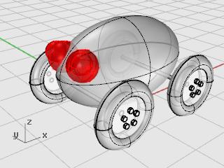
1 This tutorial demonstrates using solid primitives and simple transforms. You will learn how to: Enter coordinates to place points exactly. Draw a free-form curve and polygon. Create a pipe along a curve. Use a polar array to copy objects in a circular pattern. Extrude a curve to create a surface. Use planar mode. Enter coordinates When you pick a point with the mouse, the point lies on the construction plane of the active viewport unless you use a modeling aid such as object snap or elevator mode. When Rhino prompts for a point, you can enter x-, y-, and z-coordinates instead of picking a point. Each viewport has its own construction plane on which its x- and y-coordinates lie. The z-coordinate for the active viewport is perpendicular to the x-y plane. The grid is a visual representation of the construction plane. The intersection of the dark red and green lines shows the location of the origin point (x=0, y=0, z=0) of the coordinate system. Draw the pull toy body This exercise uses x-, y-, and z-coordinates to accurately place points. When you are to type coordinates, type them just as they are shown in the manual. The format is x,y,z. For example, type 1,1,4. You must type the commas. This sets the point at x=1, y=1, and z=4 in the active viewport. Whenever you type points, look in all viewports at where the point is placed so you can start getting an idea of how coordinate entry works. Note: Pay close attention to the viewport required in each instruction. 87

2 Start the model 1. Begin a New model. 2. In the Open Template File dialog box, select Small Objects - Centimeters.3dm, and click Open. Draw an ellipsoid 1. Turn on Ortho. 2. On the Solid menu, click Ellipsoid > From Center. 3. With the Top viewport active, at the Ellipsoid center prompt, type 0,0,11, and press Enter. This places the center point of the ellipsoid at x=0, y=0, and z=11. Look at the point in the Perspective viewport. 4. At the End of first axis prompt, type 15, and press Enter. 5. Move the cursor to the right to show the direction and click. 6. At the End of second axis prompt, type 8, and press Enter. 7. Move the cursor up to show the direction and click. This sets the width of the ellipsoid. 88


3 8. At the End of third axis prompt, type 9, and press Enter. You now have an egg shape that has different dimensions in all three directions. 9. Rotate the perspective viewport so you are looking along the x-axis as illustrated. Turn on Shaded display mode in the Perspective viewport. Draw the axles and wheel hubs The axles and wheel hubs are cylinders. The axles are long, thin cylinders, and the wheel hubs are short, fat cylinders. You are going to make one axle and one complete wheel. You will then mirror the complete wheel to the other side. You can then either mirror or copy the complete axle and wheel set to the front of the toy. 89


4 Create the axle 1. On the Solid menu, click Cylinder. 2. With the Front viewport active, at the Base of cylinder prompt, for the location of the cylinder's center, type 9,6.5,10, and press Enter. 3. At the Radius prompt, type.5, and press Enter. 4. At the End of cylinder prompt, type -20, and press Enter. 90


5 Create a wheel hub 1. On the Solid menu, click Cylinder. 2. With the Front viewport active, at the Base of cylinder prompt, type 9,6.5,10, and press Enter. 3. At the Radius prompt, type 4, and press Enter. 4. At the End of cylinder prompt, type 2, and press Enter. 91
 prompt, type 6, and press Enter. 3. In the Front viewport, at the Center of inscribed polygon prompt, type 9,8,12, and press Enter.")
6 Draw the lug nuts You will make the lug nuts by extruding a hexagonal polygon curve. Create a hexagon 1. On the Curve menu, click Polygon > Center, Radius. 2. At the Center of inscribed polygon ( NumSides=4 ) prompt, type 6, and press Enter. 3. In the Front viewport, at the Center of inscribed polygon prompt, type 9,8,12, and press Enter. This will place the polygon right on the surface of the wheel hub. 4. At the Corner of polygon prompt, type.5, and press Enter. 5. In the Front viewport drag the cursor as illustrated, and click to position the hexagon. Make a solid from the polygon 1. In any viewport, select the hexagon you just created. 2. On the Solid menu, click Extrude Planar Curve > Straight. 3. At the Extrusion distance prompt, notice the command-line options. Set the options as follows: Direction - use default BothSides=No Solid=Yes DeleteInput=Yes ToBoundary - use default SplitAtTangents=No SetBasePoint - use default If the option is not set as listed above, click the option to change it. 92
, and press Enter. Array the lug nuts To create the lug nuts on the first wheel, you are going to use a polar (circular) array. An array is a set of copies of an object.")
7 4. At the Extrusion Distance prompt, type -.5 (Notice the negative number. If you type a positive number at this point, the nuts will be buried in the wheel hub. You want them to stick out.), and press Enter. Array the lug nuts To create the lug nuts on the first wheel, you are going to use a polar (circular) array. An array is a set of copies of an object. You control how the copies are made. A polar array copies the objects around a central point. The objects are rotated as they are copied. Array the nuts 1. Select the lug nut. 2. On the Transform menu, click Array > Polar. 3. With the Front viewport active, at the Center of polar array prompt, use the Cen object snap to snap to the center of the hub. 4. At the Number of elements prompt, type 5, and press Enter. 5. At the Angle to fill <360> prompt, press Enter. 93


8 6. At the Press Enter to accept prompt, check the preview, and press Enter. Draw the tires The tires are a solid form called a torus, which looks like a donut. When you are drawing a torus, the first radius is the radius of a circle around which the tube is drawn. The second radius is the radius of the tube itself. To draw the tires, you will draw the center of the torus tube a bit larger than the diameter of the wheel hub. The tube itself is slightly larger than the hub. This makes it dip into the hub. Create a torus for the tires 1. On the Solid menu, click Torus. 2. In the Front viewport, at the Center of torus prompt, type 9,6.5,11, and press Enter. This places the center of the torus at the same point as the center of the wheel hub. 3. At the Radius prompt, type 5, and press Enter. This makes the radius of the torus tube one unit bigger than the wheel hub. 94


9 4. At the Second radius prompt, type 1.5, and press Enter. This makes the inner dimension of the torus tube.5 units smaller than the wheel hub. Mirror the wheels Now that you have a whole wheel created, you can use the Mirror command to create the other three. Mirror the wheel to the other side 1. In the Top viewport, use a window to select the wheel as illustrated. 2. On the Transform menu, click Mirror. 3. At the Start of mirror plane prompt, type 0,0,0, and press Enter. 95

10 4. At the End of mirror plane prompt, with Ortho on, drag to the right in the Top viewport as illustrated and click. Mirror the front wheels and axle 1. In the Top viewport, use a window to select the wheels and axle as illustrated. 2. On the Transform menu, click Mirror. 3. At the Start of mirror plane prompt, type 0,0,0, and press Enter. 96

11 4. At the End of mirror plane prompt, with Ortho on, drag down in the Top viewport as illustrated and click. Draw the eyes You are going to draw a sphere for an eye and a smaller sphere for the pupil. Create an eye using a sphere 1. On the Solid menu, click Sphere > Center, Radius. 2. At the Center of sphere prompt, in the Top viewport, type -12,-3,14, and press Enter. 97

12 3. At the Radius prompt, type 3 and press Enter. Create the eye pupil 1. Repeat the Sphere command. 2. At the Center of sphere prompt, in the Top viewport, type -13,-4,15, and press Enter. 3. At the Radius prompt, type 2 and press Enter. 98
13 Mirror the eye 1. In the Top viewport, use a window to select the eye as illustrated. 2. On the Transform menu, click Mirror. 3. At the Start of mirror plane prompt, type 0 (this is a shortcut for typing 0,0,0), and press Enter. 4. At the End of mirror plane prompt, with Ortho on, drag to the left in the Top viewport as illustrated and click. 99
14 100


15 Make the pull cord To make the cord, you are going to draw a freehand curve using elevator and planar mode. When the curve is complete, use the Pipe command to make it a thick solid. Set up the view 1. Zoom out in all the viewports; you are going to need some space to work. 2. On the status bar, turn Planar mode on, and turn Ortho off. 3. In the Osnap dialog box, click Disable to turn off all object snaps. Create the pull cord at the front of the toy 1. On the Curve menu, click Free-form > Control Points. 2. At the Start of curve prompt, in the Top viewport, hold the Ctrl key to activate elevator mode and click near the front end of the body ellipsoid. 3. Move the cursor to the Front viewport, drag the marker near the end of the ellipsoid, and click. 101


16 4. At the Next point prompt, click to the left of the ellipsoid in the Top viewport. Planar mode keeps successive points at the same construction plane elevation. Planar mode can be overridden with elevator mode or object snaps. Watch the curve in the Top and Front viewports. 5. At the Next point prompt, use elevator mode to add another point in the Top viewport. 6. At the Next point prompts, turn off Planar mode and click several more points in the Top viewport to create a curved line. 102


17 Notice that the points are projected to the Top construction plane. Make the cord handle 1. Draw an Ellipsoid with the Diameter option to represent a handle at the end of the curve. 2. At the Start of first axis prompt, use the End object snap to pick the end of the cord curve. 3. At the End of first axis prompt, type 10 to set the length, and press Enter. 4. Drag the direction so it lines up with the cord curve and click to set the direction. This does not have to be very accurate. 103
18 5. At the End of second axis prompt, type 4, press Enter, and drag to set the direction. 6. At the End of third axis prompt, type 2, and press Enter. Thicken the curve with a pipe 1. Select the curve you just made at the front of the pull toy. 2. On the Solid menu, click Pipe. 3. At the Start radius prompt, type.2, and press Enter. 4. At the End radius prompt, press Enter. 104

19 5. At the Point for next radius prompt, press Enter. The pipe will be the same diameter for the full length of the curve. 105
Create a Rubber Duck. This tutorial shows you how to. Create simple surfaces. Rebuild a surface. Edit surface control points. Draw and project curves
 Page 1 of 24 Create a Rubber Duck This exercise focuses on the free form, squishy aspect. Unlike the flashlight model, the exact size and placement of the objects is not critical. The overall form is the
LESSON 14 LEARNING OBJECTIVES. After completing this lesson, you will be able to:
 LEARNING OBJECTIVES After completing this lesson, you will be able to: 1. Construct 6 Solid model Primitives: Box, Sphere, Cylinder, Cone, Wedge and Torus LESSON 14 CONSTRUCTING SOLID PRIMITIVES AutoCAD
3D Design with 123D Design
 3D Design with 123D Design Introduction: 3D Design involves thinking and creating in 3 dimensions. x, y and z axis Working with 123D Design 123D Design is a 3D design software package from Autodesk. A
COMPUTER AIDED DESIGN CURRICULLOM RHINO BASED 3D DESIGN
 COMPUTER AIDED DESIGN CURRICULLOM RHINO BASED 3D DESIGN S.no. CONTENTS Page no S. no. CONTENTS PAGE no. 1. Introduction 1 2. Necessary of Rhino in Designing 2 3. Working with 3D Models 3 4. Object Types
Exercise Guide. Published: August MecSoft Corpotation
 VisualCAD Exercise Guide Published: August 2018 MecSoft Corpotation Copyright 1998-2018 VisualCAD 2018 Exercise Guide by Mecsoft Corporation User Notes: Contents 2 Table of Contents About this Guide 4
3D ModelingChapter1: Chapter. Objectives
 Chapter 1 3D ModelingChapter1: The lessons covered in this chapter familiarize you with 3D modeling and how you view your designs as you create them. You also learn the coordinate system and how you can
Rhinoceros NURBS modeling for Windows. Version 1.0 Training Manual Level 1
 Rhinoceros NURBS modeling for Windows Version 1.0 Training Manual Level 1 rhinolevel 1.doc Robert McNeel & Associates 1997. All Rights Reserved. Printed in U.S.A. Copyright by Robert McNeel & Associates.
NURBS modeling for Windows. Training Manual Level 1
 NURBS modeling for Windows Training Manual Level 1 Rhino Level 1 Training 2nd Ed.doc Robert McNeel & Associates 1997-2000 All Rights Reserved. Printed in U.S.A. Copyright by Robert McNeel & Associates.
Solid Modeling: Part 1
 Solid Modeling: Part 1 Basics of Revolving, Extruding, and Boolean Operations Revolving Exercise: Stepped Shaft Start AutoCAD and use the solid.dwt template file to create a new drawing. Create the top
Spring 2011 Workshop ESSENTIALS OF 3D MODELING IN RHINOCEROS February 10 th 2011 S.R. Crown Hall Lower Core Computer Lab
 [1] Open Rhinoceros. PART 1 INTRODUCTION [4] Click and hold on the Boundary Lines in where they form a crossing and Drag from TOP RIGHT to BOTTOM LEFT to enable only the PERSPECTIVE VIEW. [2] When the
Lesson 5 Solid Modeling - Constructive Solid Geometry
 AutoCAD 2000i Tutorial 5-1 Lesson 5 Solid Modeling - Constructive Solid Geometry Understand the Constructive Solid Geometry Concept. Create a Binary Tree. Understand the basic Boolean Operations. Create
Arch 226 CAD in Practice Fall 2011 Class-06 Rhino. [Starting Rhino] Viewports Command Line Prompts, Options Status Bar Toolbars
![Arch 226 CAD in Practice Fall 2011 Class-06 Rhino. [Starting Rhino] Viewports Command Line Prompts, Options Status Bar Toolbars](/thumbs/92/110467085.jpg "Arch 226 CAD in Practice Fall 2011 Class-06 Rhino. [Starting Rhino] Viewports Command Line Prompts, Options Status Bar Toolbars") [Starting ] Viewports Command Line Prompts, Options Status Bar Toolbars [Understanding Views] Zoom, Pan, and Rotate the View Mouse Wheel Zoom Right Mouse Button Pan, Rotate, and Zoom Pan- shift/right click,
[Starting ] Viewports Command Line Prompts, Options Status Bar Toolbars [Understanding Views] Zoom, Pan, and Rotate the View Mouse Wheel Zoom Right Mouse Button Pan, Rotate, and Zoom Pan- shift/right click,
Chapter 15: Penguin - Point Editing and Blending
 This tutorial demonstrates point-editing techniques including moving and scaling control points and adding knots to surfaces to increase control. In addition, you will use blends to create smooth transitions
Chapter 1: Introduction
 Modeling in 3-D is the process of creating a mathematical representation of an object's surfaces. The resulting model is displayed on your screen as a two-dimensional image. Rhino provides tools for creating,
S206E Lecture 3, 5/15/2017, Rhino 2D drawing an overview
 Copyright 2017, Chiu-Shui Chan. All Rights Reserved. S206E057 Spring 2017 Rhino 2D drawing is very much the same as it is developed in AutoCAD. There are a lot of similarities in interface and in executing
Autodesk Inventor - Basics Tutorial Exercise 1
 Autodesk Inventor - Basics Tutorial Exercise 1 Launch Inventor Professional 2015 1. Start a New part. Depending on how Inventor was installed, using this icon may get you an Inch or Metric file. To be
Lesson 1 Parametric Modeling Fundamentals
 1-1 Lesson 1 Parametric Modeling Fundamentals Create Simple Parametric Models. Understand the Basic Parametric Modeling Process. Create and Profile Rough Sketches. Understand the "Shape before size" approach.
Introduction to AutoCAD 2012
 Introduction to AutoCAD 2012 Alf Yarwood Chapter 13 Exercise 1 1. Open AutoCAD 2012 with a double-click on its shortcut icon in the Windows desktop. 2. Open the template acadiso3d.dwt. 3. Make two new
Autodesk Inventor 2019 and Engineering Graphics
 Autodesk Inventor 2019 and Engineering Graphics An Integrated Approach Randy H. Shih SDC PUBLICATIONS Better Textbooks. Lower Prices. www.sdcpublications.com Powered by TCPDF (www.tcpdf.org) Visit the
Rhino Interface. Menus Command History Command Prompt. Toolbars. Viewport Title. Viewports. Common Shortcuts. Object Snaps.
 Rhino Interface Menus Command History Command Prompt Toolbars Viewport Title LMB: activate viewport without losing selection Double Click: maximise viewport RMB: show viewport options: wireframe, shaded,
Rhinoceros NURBS modeling for Windows. Training Manual Level 1
 Rhinoceros NURBS modeling for Windows Training Manual Level 1 R30TML1-08-2005 Rhinoceros Level 1 Training Manual v3.0 Robert McNeel & Associates 2005 All Rights Reserved. Printed in U.S.A. Copyright by
Modeling a Gear Standard Tools, Surface Tools Solid Tool View, Trackball, Show-Hide Snaps Window 1-1
 Modeling a Gear This tutorial describes how to create a toothed gear. It combines using wireframe, solid, and surface modeling together to create a part. The model was created in standard units. To begin,
Google SketchUp. and SketchUp Pro 7. The book you need to succeed! CD-ROM Included! Kelly L. Murdock. Master SketchUp Pro 7 s tools and features
 CD-ROM Included! Free version of Google SketchUp 7 Trial version of Google SketchUp Pro 7 Chapter example files from the book Kelly L. Murdock Google SketchUp and SketchUp Pro 7 Master SketchUp Pro 7 s
Solid surface modeling in AutoCAD
 Solid surface modeling in AutoCAD Introduction into 3D modeling Managing views of 3D model Coordinate Systems 1 3D model advantages ability to view the whole model looking inside the model collision checking
Inventor 201. Work Planes, Features & Constraints: Advanced part features and constraints
 Work Planes, Features & Constraints: 1. Select the Work Plane feature tool, move the cursor to the rim of the base so that inside and outside edges are highlighted and click once on the bottom rim of the
Tutorial Second Level
 AutoCAD 2018 Tutorial Second Level 3D Modeling Randy H. Shih SDC PUBLICATIONS Better Textbooks. Lower Prices. www.sdcpublications.com Powered by TCPDF (www.tcpdf.org) Visit the following websites to learn
GEO 154 CARTOGRAPHY II- PLOTTING USING AUTOCAD- ASSIGMENT HELP
 GEO 154 CARTOGRAPHY II- PLOTTING USING AUTOCAD- ASSIGMENT HELP DOCUMENT. For one to two reasons data may not be in a format that can be integrated into AutoCAD software, but coordinates may be separated
The Department of Construction Management and Civil Engineering Technology CMCE-1110 Construction Drawings 1 Lecture Introduction to AutoCAD What is
 The Department of Construction Management and Civil Engineering Technology CMCE-1110 Construction Drawings 1 Lecture Introduction to AutoCAD What is AutoCAD? The term CAD (Computer Aided Design /Drafting)
Acknowledgement INTRODUCTION
 Submitted by: 1 Acknowledgement INTRODUCTION Computers are increasingly being used for doing engineering drawings and graphics work because computers allow the graphics designer or the draughtsman to change
Tutorial 3: Constructive Editing (2D-CAD)
") (2D-CAD) The editing done up to now is not much different from the normal drawing board techniques. This section deals with commands to copy items we have already drawn, to move them and to make multiple
(2D-CAD) The editing done up to now is not much different from the normal drawing board techniques. This section deals with commands to copy items we have already drawn, to move them and to make multiple
solidthinking Environment...1 Modeling Views...5 Console...13 Selecting Objects...15 Working Modes...19 World Browser...25 Construction Tree...
 Copyright 1993-2009 solidthinking, Inc. All rights reserved. solidthinking and renderthinking are trademarks of solidthinking, Inc. All other trademarks or service marks are the property of their respective
Rhinoceros. modeling tools for designers. Training Manual Level 1
 Rhinoceros modeling tools for designers Training Manual Level 1 RH50-TM-L1-Sep-2013 Rhinoceros v5.0, Level 1, Training Manual Revised 9/30/2013, Mary Fugier mary@mcneel.com Q&A 9/30/2013,, Jerry Hambly
Lesson 2 Constructive Solid Geometry Concept. Parametric Modeling with I-DEAS 2-1
 Lesson 2 Constructive Solid Geometry Concept Parametric Modeling with I-DEAS 2-1 2-2 Parametric Modeling with I-DEAS Introduction In the 1980s, one of the main advancements in Solid Modeling was the development
Maya Lesson 3 Temple Base & Columns
 Maya Lesson 3 Temple Base & Columns Make a new Folder inside your Computer Animation Folder and name it: Temple Save using Save As, and select Incremental Save, with 5 Saves. Name: Lesson3Temple YourName.ma
Rhinoceros NURBS modeling for Windows
 Rhinoceros NURBS modeling for Windows Training Manual Level 1 Version 4.0 R40TML5-17-2007 Rhinoceros Level 1 Training Manual v4.0 Robert McNeel & Associates 2006 All Rights Reserved. Printed in U.S.A.
Chapter 6: Create Surfaces from Curves
 A common way of working in 3-D is to draw curves that represent edges, profiles, cross-sections, or other surface features and then to use surfacing commands to create surfaces from those curves. Edge
1st Point. 2nd Point. hold shift & drag along Y. Splines
 Splines STEP 1: open 3DS Max _ from the Command Panel under the Create tab click on Shapes (note: shapes are really Splines) _ under Object Type click on Ellipse STEP 2: Expand the Keyboard Entry tab type
Autodesk Fusion 360: Model. Overview. Modeling techniques in Fusion 360
 Overview Modeling techniques in Fusion 360 Modeling in Fusion 360 is quite a different experience from how you would model in conventional history-based CAD software. Some users have expressed that it
Parametric Modeling with. Autodesk Fusion 360. First Edition. Randy H. Shih SDC. Better Textbooks. Lower Prices.
 Parametric Modeling with Autodesk Fusion 360 First Edition Randy H. Shih SDC PUBLICATIONS Better Textbooks. Lower Prices. www.sdcpublications.com Powered by TCPDF (www.tcpdf.org) Visit the following websites
QUICK-START TUTORIALS
 PUERMC02_0132276593.QXD 08/09/2006 06:05 PM Page 83 QUICK-START TUTORIALS Chapter Objectives Create two real 3D modeling projects, starting them from scratch. Know the difference between representing 3D
Using Object Snap to Draw a Rug Design
 Using Object Snap to Draw a Rug Design The objective of the rest of this tutorial is to learn the use of object snap and hatch. Because AutoCAD is based on vectors and coordinate geometry, it can easily
CADian Training Manual Step III. 3D Modeling
 CADian Training Manual Step III 3D Modeling Index Page No. Introduction 3 Viewing 3D objects 4 Vpoint 4 DDvpoint 5 Surface Modeling 7 3Dface 7 Pface 8 Mesh 9 Pedit 11 Rule Surf 13 Tab Surf 14 Revsurf 15
3D Visualization and Solid Primitive Conceptual Design in AutoCAD
 3D Visualization and Solid Primitive Conceptual Design in AutoCAD Craig P. Black - Fox Valley Technical College GD111-3P This class will help you understand the viewing techniques in 3D AutoCAD and how
Rhinoceros NURBS modeling for Windows
 Rhinoceros NURBS modeling for Windows Training Manual Level 1 Version 4.0 R40TML1 Oct-2008 Rhinoceros Level 1 Training Manual v4.0 Robert McNeel & Associates 2008 All Rights Reserved. Printed in U.S.A.
SOLIDWORKS 2016 and Engineering Graphics
 SOLIDWORKS 2016 and Engineering Graphics An Integrated Approach Randy H. Shih SDC PUBLICATIONS Better Textbooks. Lower Prices. www.sdcpublications.com Powered by TCPDF (www.tcpdf.org) Visit the following
SolidWorks 2013 and Engineering Graphics
 SolidWorks 2013 and Engineering Graphics An Integrated Approach Randy H. Shih SDC PUBLICATIONS Schroff Development Corporation Better Textbooks. Lower Prices. www.sdcpublications.com Visit the following
Randy H. Shih. Jack Zecher PUBLICATIONS
 Randy H. Shih Jack Zecher PUBLICATIONS WWW.SDCACAD.COM AutoCAD LT 2000 MultiMedia Tutorial 1-1 Lesson 1 Geometric Construction Basics! " # 1-2 AutoCAD LT 2000 MultiMedia Tutorial Introduction Learning
TUTORIAL 03: RHINO DRAWING & ORGANIZATIONAL AIDS. By Jeremy L Roh, Professor of Digital Methods I UNC Charlotte s School of Architecture
 TUTORIAL 03: RHINO DRAWING & ORGANIZATIONAL AIDS By Jeremy L Roh, Professor of Digital Methods I UNC Charlotte s School of Architecture Modeling in 3D requires the use of various drawing and organizational
StickFont Editor v1.01 User Manual. Copyright 2012 NCPlot Software LLC
 StickFont Editor v1.01 User Manual Copyright 2012 NCPlot Software LLC StickFont Editor Manual Table of Contents Welcome... 1 Registering StickFont Editor... 3 Getting Started... 5 Getting Started...
3 AXIS STANDARD CAD. BobCAD-CAM Version 28 Training Workbook 3 Axis Standard CAD
 3 AXIS STANDARD CAD This tutorial explains how to create the CAD model for the Mill 3 Axis Standard demonstration file. The design process includes using the Shape Library and other wireframe functions
COMPUTER AIDED ARCHITECTURAL GRAPHICS FFD 201/Fall 2013 HAND OUT 1 : INTRODUCTION TO 3D
 COMPUTER AIDED ARCHITECTURAL GRAPHICS FFD 201/Fall 2013 INSTRUCTORS E-MAIL ADDRESS OFFICE HOURS Özgür Genca ozgurgenca@gmail.com part time Tuba Doğu tubadogu@gmail.com part time Şebnem Yanç Demirkan sebnem.demirkan@gmail.com
Parametric Modeling. With. Autodesk Inventor. Randy H. Shih. Oregon Institute of Technology SDC PUBLICATIONS
 Parametric Modeling With Autodesk Inventor R10 Randy H. Shih Oregon Institute of Technology SDC PUBLICATIONS Schroff Development Corporation www.schroff.com www.schroff-europe.com 2-1 Chapter 2 Parametric
SolidWorks Intro Part 1b
 SolidWorks Intro Part 1b Dave Touretzky and Susan Finger 1. Create a new part We ll create a CAD model of the 2 ½ D key fob below to make on the laser cutter. Select File New Templates IPSpart If the SolidWorks
Table of contents 2 / 117
 1 / 117 Table of contents Welcome... 4 System requirements... 5 Getting help... 6 Commands... 7 Primitives... 10 Plane... 11 Box... 13 Torus... 15 Cylinder... 18 Sphere... 20 Ellipsoid... 22 Cone... 24
The Beret-Palette Ring. Designed by Luiz Maia
 The Beret-Palette Ring Designed by Luiz Maia Table of Contents Part I Description of the model.p. 3 Part II Building the ring..p. 4-25 The beret-palette....p. 4-11 The shank/paintbrush p. 12 The handle
User Guide. for. JewelCAD Professional Version 2.0
 User Guide Page 1 of 121 User Guide for JewelCAD Professional Version 2.0-1 - User Guide Page 2 of 121 Table of Content 1. Introduction... 7 1.1. Purpose of this document... 7 2. Launch JewelCAD Professional
4) Finish the spline here. To complete the spline, double click the last point or select the spline tool again.
 Finish the spline here. To complete the spline, double click the last point or select the spline tool again.") 1) Select the line tool 3) Move the cursor along the X direction (be careful to stay on the X axis alignment so that the line is perpendicular) and click for the second point of the line. Type 0.5 for
1) Select the line tool 3) Move the cursor along the X direction (be careful to stay on the X axis alignment so that the line is perpendicular) and click for the second point of the line. Type 0.5 for
3D Modeling and Design Glossary - Beginner
 3D Modeling and Design Glossary - Beginner Align: to place or arrange (things) in a straight line. To use the Align tool, select at least two objects by Shift left-clicking on them or by dragging a box
Solid Problem Ten. In this chapter, you will learn the following to World Class standards:
 C h a p t e r 11 Solid Problem Ten In this chapter, you will learn the following to World Class standards: 1. Sketch of Solid Problem Ten 2. Starting a 3D Part Drawing 3. Modifying How the UCS Icon is
SolidWorks 2½D Parts
 SolidWorks 2½D Parts IDeATe Laser Micro Part 1b Dave Touretzky and Susan Finger 1. Create a new part In this lab, you ll create a CAD model of the 2 ½ D key fob below to make on the laser cutter. Select
Calypso Construction Features. Construction Features 1
 Calypso 1 The Construction dropdown menu contains several useful construction features that can be used to compare two other features or perform special calculations. Construction features will show up
Digitizer Leapfrogging
 Digitizer Leapfrogging Leapfrogging lets you digitize objects that are larger than your digitizing arm. You start with one section of the object, then leapfrog around by creating leapfrog stations in both
Technique or Feature Where Introduced
 Part 6: Keypad 4 Mirrored features Patterned features First extrusion Rounded corners In the earpiece part, you defined a radial pattern, one that created new instances of a feature at intervals around
A Guide to Autodesk Maya 2015
 A Guide to Autodesk Maya 2015 Written by Mitchell Youngerman Table of Contents Layout of Toolbars...pg 1 Creating Objects...pg 2 Selecting & Deselecting Objects...pg 3 Changing Perspective... pg 4 Transforming
FormZ Tips created by Phil Jones, edited by Nancy Cheng, University of Oregon 11/16/05
 FormZ Tips created by Phil Jones, edited by Nancy Cheng, University of Oregon 11/16/05 window tools: 1 2 3 4 5 6 7 8 9 1 set reference plane use this to choose between standard reference planes. 2 perpendicular
Module 1: Basics of Solids Modeling with SolidWorks
 Module 1: Basics of Solids Modeling with SolidWorks Introduction SolidWorks is the state of the art in computer-aided design (CAD). SolidWorks represents an object in a virtual environment just as it exists
An Introduction to Autodesk Inventor 2012 and AutoCAD Randy H. Shih SDC PUBLICATIONS. Schroff Development Corporation
 An Introduction to Autodesk Inventor 2012 and AutoCAD 2012 Randy H. Shih SDC PUBLICATIONS www.sdcpublications.com Schroff Development Corporation Visit the following websites to learn more about this book:
Parametric Modeling. with. Autodesk Inventor Randy H. Shih. Oregon Institute of Technology SDC
 Parametric Modeling with Autodesk Inventor 2009 Randy H. Shih Oregon Institute of Technology SDC PUBLICATIONS Schroff Development Corporation www.schroff.com Better Textbooks. Lower Prices. 2-1 Chapter
GETTING STARTED TABLE OF CONTENTS
 Sketchup Tutorial GETTING STARTED Sketchup is a 3D modeling program that can be used to create 3D objects in a 2D environment. Whether you plan to model for 3D printing or for other purposes, Sketchup
The Villa Savoye ( ), Poisy, Paris.
, Poisy, Paris.") Learning SketchUp Villa Savoye This tutorial will involve modeling the Villa Savoye by Le Corbusier Files needed to complete this tutorial are available in Mr. Cochran s Web Site The Villa Savoye (1929-1931),
Learning SketchUp Villa Savoye This tutorial will involve modeling the Villa Savoye by Le Corbusier Files needed to complete this tutorial are available in Mr. Cochran s Web Site The Villa Savoye (1929-1931),
Skateboard. Hanger. in the Feature Manager and click Sketch. (S) on the Sketch. Line
 on the Sketch. Line") Chapter 3 Skateboard Hanger A. Sketch 1. Step 1. Click File Menu > New, click Part Metric and OK. Step 2. Click Right Plane from the Content toolbar, Fig. 1. in the Feature Manager and click Sketch Step
Chapter 3 Skateboard Hanger A. Sketch 1. Step 1. Click File Menu > New, click Part Metric and OK. Step 2. Click Right Plane from the Content toolbar, Fig. 1. in the Feature Manager and click Sketch Step
Chapter 4. Part 1 AutoCAD Basics
 Chapter 4. Part 1 AutoCAD Basics Chapter Objectives Describe the AutoCAD screen layout. Perform an AutoCAD drawing setup, including setting units, limits, layers, linetypes, and lineweights. Explain the
Geometry Vocabulary. acute angle-an angle measuring less than 90 degrees
 Geometry Vocabulary acute angle-an angle measuring less than 90 degrees angle-the turn or bend between two intersecting lines, line segments, rays, or planes angle bisector-an angle bisector is a ray that
A Comprehensive Introduction to SolidWorks 2011
 A Comprehensive Introduction to SolidWorks 2011 Godfrey Onwubolu, Ph.D. SDC PUBLICATIONS www.sdcpublications.com Schroff Development Corporation Chapter 2 Geometric Construction Tools Objectives: When
3D Modeler Creating Custom myhouse Symbols
 3D Modeler Creating Custom myhouse Symbols myhouse includes a large number of predrawn symbols. For most designs and floorplans, these should be sufficient. For plans that require that special table, bed,
Each trainee receives the official 260 page courseware as part of attending this course.
 Level 1 NURBS modelling with Rhino Course Outline This course is for anyone new, or nearly new, to Rhino. Recognised as THE introductory course for Rhino, all trainees receive an Official Certificate on
Photocopiable/digital resources may only be copied by the purchasing institution on a single site and for their own use ZigZag Education, 2013
 SketchUp Level of Difficulty Time Approximately 15 20 minutes Photocopiable/digital resources may only be copied by the purchasing institution on a single site and for their own use ZigZag Education, 2013
An Introduction to Autodesk Inventor 2013 and AutoCAD
 An Introduction to Autodesk Inventor 2013 and AutoCAD 2013 Randy H. Shih SDC PUBLICATIONS Schroff Development Corporation Better Textbooks. Lower Prices. www.sdcpublications.com Visit the following websites
It is a good idea to practice View Control tools for 5 minutes at the start of every 3D session, before doing any other work.
 3D View Control Module Overview All the 2D view controls, such as Fit View, Zoom In and Out, Window Area, and Pan, can be used in 3D. As in 2D, elements to the left, right, above, or below can be excluded
An Introduction to Autodesk Inventor 2010 and AutoCAD Randy H. Shih SDC PUBLICATIONS. Schroff Development Corporation
 An Introduction to Autodesk Inventor 2010 and AutoCAD 2010 Randy H. Shih SDC PUBLICATIONS Schroff Development Corporation www.schroff.com 2-1 Chapter 2 Parametric Modeling Fundamentals Create Simple Extruded
TUTORIAL 01: RHINO INTERFACE. By Jeremy L Roh, Professor of Digital Methods I UNC Charlotte s School of Architecture
 TUTORIAL 01: RHINO INTERFACE By Jeremy L Roh, Professor of Digital Methods I UNC Charlotte s School of Architecture Upon opening Rhinoceros 4.0, a Startup Template Dialog Box will appear. Left-click on
Advances in MicroStation 3D
 MW1HC515 Advances in MicroStation 3D Hands-on class sponsored by the Bentley Institute Presenter: Sam Hendrick, Senior MicroStation Product Consultant Bentley Systems, Incorporated 685 Stockton Drive Exton,
Ansoft HFSS Windows Screen Windows. Topics: Side Window. Go Back. Contents. Index
 Modifying Coordinates Entering Data in the Side Windows Modifying Snap To Absolute Relative Each screen in divided up into many windows. These windows can allow you to change the coordinates of the model,
Revit Architecture 2015 Basics
 Revit Architecture 2015 Basics From the Ground Up Elise Moss Authorized Author SDC P U B L I C AT I O N S Better Textbooks. Lower Prices. www.sdcpublications.com Powered by TCPDF (www.tcpdf.org) Visit
Tutorial - Steering Wheel
 Tutorial - Steering Wheel (written by Jacob Tremmel, Student at Altair) This tutorial is about modeling (CAD) and rendering of a Steering Wheel with Altair s solidthinking Evolve 9.0. 1 Modeling 1. At
PLAY VIDEO. Fences can be any shape from a simple rectangle to a multisided polygon, even a circle.
 Chapter Eight Groups PLAY VIDEO INTRODUCTION There will be times when you need to perform the same operation on several elements. Although this can be done by repeating the operation for each individual
QuickTutor. An Introductory SilverScreen Modeling Tutorial. Solid Modeler
 QuickTutor An Introductory SilverScreen Modeling Tutorial Solid Modeler TM Copyright Copyright 2005 by Schroff Development Corporation, Shawnee-Mission, Kansas, United States of America. All rights reserved.
EXERCISE 2: MODELING MINOAN COLUMNS
 Minoan Column at the Palace of Minos, Crete CARLI Digital Collections EXERCISE 2: MODELING MINOAN COLUMNS ASSIGNMENT: In this exercise you will create an architectural element, a Minoan shaped column,
TUTORIAL 07: RHINO STEREOTOMIC MODELING PART 2. By Jeremy L Roh, Professor of Digital Methods I UNC Charlotte s School of Architecture
 TUTORIAL 07: RHINO STEREOTOMIC MODELING PART 2 By Jeremy L Roh, Professor of Digital Methods I UNC Charlotte s School of Architecture This tutorial will explore the Stereotomic Modeling Methods within
Mesh Modeling Vase and Flower
 Course: 3D Design Title: Mesh Modeling Vase and Flower Dropbox File: VaseAndFlower.zip Blender: Version 2.45 Level: Beginning Author: Neal Hirsig (nhirsig@tufts.edu) Mesh Modeling Vase and Flower In this
Freeform / Freeform PLUS
 Freeform / Freeform PLUS WORKING WITH FREEFORM Work from Coarse Clay to Fine When creating new models from scratch, it is best to first create a rough shape using a coarse clay setting such as Rough Shape
Alibre Design Tutorial - Simple Revolve Translucent Glass Lamp Globe
 Alibre Design Tutorial - Simple Revolve Translucent Glass Lamp Globe Part Tutorial Exercise 2: Globe-1 In this Exercise, We will set System Parameters first. Then, in sketch mode, we will first Outline
December 3, :30 to 5:30 pm. Speaker Name: Tom Short, P.E. Course Title: Taking A Step Into The World Of 3D
 Las Vegas, Nevada December 3, 2002 1:30 to 5:30 pm Speaker Name: Tom Short, P.E. Course Title: Taking A Step Into The World Of 3D Course ID: GD122 Course Outline: Are you an experienced AutoCAD 2D user
How to...create a Video VBOX Gauge in Inkscape. So you want to create your own gauge? How about a transparent background for those text elements?
 BASIC GAUGE CREATION The Video VBox setup software is capable of using many different image formats for gauge backgrounds, static images, or logos, including Bitmaps, JPEGs, or PNG s. When the software
This is the opening view of blender.
 This is the opening view of blender. Note that interacting with Blender is a little different from other programs that you may be used to. For example, left clicking won t select objects on the scene,
CO 2 Shell Car. Body. in the Feature Manager and click Sketch from the context toolbar, Fig. 1. on the Standard Views toolbar.
 CO 2 Shell Car Chapter 2 Body A. Save as "BODY". Step 1. If necessary, open your BLANK file. Step 2. Click File Menu > Save As. Step 3. Key-in BODY for the filename and press ENTER. B. FRONT Wheel Shell.
SOLIDWORKS: Lesson III Patterns & Mirrors. UCF Engineering
 SOLIDWORKS: Lesson III Patterns & Mirrors UCF Engineering Solidworks Review Last lesson we discussed several more features that can be added to models in order to increase their complexity. We are now
solidthinking User Interface
 Lesson 1 solidthinking User Interface This lesson introduces you to the solidthinking interface. The functions described represent the tools necessary for effectively managing the modeling of a project.
Control the Workplane
 Control the Workplane This tutorial outlines the procedures to understand and control the user coordinate system (UCS). You can realign and reorient the UCS to create and modify 3D objects on 2D workplanes
Creating and Working with Solid Model Features
 This sample chapter is for review purposes only. Copyright The Goodheart-Willcox Co., Inc. ll rights reserved. Chapter Creating and Working with Solid Model Features Learning Objectives fter completing