Solidifying Wireframes
|
|
|
- Doris Gibbs
- 6 years ago
- Views:
Transcription
1 Solidifying Wireframes Vinod Srinivasan, Esan Mandal and Ergun Akleman Visualization Laboratory Department of Architecture Texas A&M University College Station, TX , USA Abstract In this paper we present a method to convert a wireframe mesh into a 2-manifold mesh consisting of cylindrical pipes in place of the edges and joints in place of the vertices in the original mesh. Our method allows users to create unique artistic depictions of common objects and structures. The resulting mesh is also more effective at conveying the overall 3D structure and any internal elements of a model when compared to regular wireframe or boundary representations. The input wireframe mesh can be any collection of linear edges; they do not have to form a manifold surface or even be connected to each other. The result is always an orientable 2-manifold surface. Our algorithm replaces every edge in the wireframe mesh with a cylindrical 3D pipe. The pipes are connected to each other using 3D joints created at the vertices in the wireframe where the edges meet. Our method has been implemented as part of a polygonal mesh modeling system and has been used to create artistic models of popular architectural structures as well as to create conceptual sketches for virtual environments. 1. Introduction and Motivation Wireframe meshes are commonly used to represent 3D objects in many modeling programs. A wireframe mesh consists of a set of vertices and a set of edges connecting those vertices. Although they represent 3D models, the individual components of the wireframe mesh (vertices and edges) are themselves thought of as having zero volume. Thus when shown on a 2D display, a wireframe mesh does not effectively convey the 3D information that it encapsulates [7]. The use of perspective projection reveals some of the depth information, but for complicated models with intricate geometry it is still not very effective. Boundary representations, such as polygonal meshes or NURBS surfaces, derived from the wireframe mesh can partly help with conveying 3D information. But in such models, internal structures are not visible, since they are occluded by exterior faces. In comparison to using polygonal meshes or NURBS surfaces, modeling using wireframes is much simpler since it has fewer constraints. Furthermore, because no face information is stored, they are efficient in conveying a lot of information with very little resources. However, the lack of faces has a drawback in that it is difficult to tell which parts of the model are solid and which are empty [7]. Wireframe modeling is particularly well suited for modeling shapes such as frame structures which resemble wireframe meshes in their overall appearance. Shapes dominated by beams and columns are also well suited for wireframe modeling. Classical architecture is replete with examples of such shapes. In recent times, frame structures, such as space frames or plane frames, have gradually increased in popularity among
 Crystal Palace, England (19th century). Designed by Joseph Paxton. (C) The Eastern Station, Lisbon (1990s). Architect: Santiago Calatrava. designers.")
![The Crystal Palace, designed in 1850 by Joseph Paxton is often cited as the first example of using pre-fabricated components [5].](/docs-images/72/67466368/images/2-1.jpg "Figure 1 shows examples of architectural designs from different periods, all of which are dominated by frame structures.")

2 (A) (B) (C) Figure 1: Examples of frame structures in architecture from 19th and 20th centuries. (A) Center Pompidou, Paris (1970s). Architects: Renzo Piano, Richard Rogers. (B) Crystal Palace, England (19th century). Designed by Joseph Paxton. (C) The Eastern Station, Lisbon (1990s). Architect: Santiago Calatrava. designers. The Crystal Palace, designed in 1850 by Joseph Paxton is often cited as the first example of using pre-fabricated components [5]. Figure 1 shows examples of architectural designs from different periods, all of which are dominated by frame structures. In spite of the prevalence of such designs, research into tools for creating such models is lacking. Van Kempen et al. in their work on computer aided drafting and three-dimensional modeling address the subject of pre-fabricated constructions, but not specific to the types of structures we are interested in [11]. Some of the authors of this paper have worked on methods to create models with large number of holes and handles and our present work develops on several of the ideas that were introduced in those papers [10, 3, 8, 9]. In this paper, we present a method to solidify a wireframe. Our method essentially converts a wireframe mesh into a 3D model in which every edge of the wireframe is replaced by a 3D pipe of finite thickness and volume, in effect creating a solid wireframe. The pipes are connected together using 3D joints at the vertices where the edges meet. The resulting model conveys the 3D information much more effectively than the plain wireframe model. Internal structures are also visible, since there are no occluding faces. Our new method has been incorporated into our existing 3D mesh modeler [1, 9] and allows the user to create very complex models with minimal effort. Creation of models like those shown in Figure 1 is greatly simplified using our tool. Users can adjust the thickness of the pipe as well as its cross-section. We chose a semi-automatic approach to ease the tedium of modeling every individual column or beam, while at the same time giving the user a fair amount of control over the resulting shape and mesh structure. One of the important features of our method is that the final mesh is guaranteed to be a valid 2-manifold surface without any cracks or gaps. This has important implications for several subdivision schemes which require that the input mesh be a valid 2-manifold [4, 6, 12]. The model created using our method is also well-suited for fabrication using a 3D printer or rapid-prototyping machine. 2. Creating the Solid Wireframe As described above, our new method creates a solid wireframe from a given wireframe mesh. The input wireframe does not have to represent a closed surface and can be an arbitrary set of edges which may or may not be connected to each other. For simplicity, we will use the term wireframe mesh to refer to a regular wireframe mesh as well as an arbitrary set of edges.
3 The creation of the solid wireframe consists of two main steps. The first one involves creation of the 3D joints at each of the vertices in the input wireframe. The second step involves connecting the joints to create the 3D pipes corresponding to each edge in the input wireframe. The following paragraphs describe these two steps in more detail. The term wireframe will be used to refer to the input mesh, while the term solid wireframe will be used to refer to the output mesh D Joints In the first step of the process, 3D joints are created at every vertex of the input wireframe. The shape of the 3D joint at a vertex depends on the number of edges incident on that vertex, and the desired thickness and cross-sectional shape of the 3D pipes. There are three steps in the joint creation process as described below End-faces For every edge in the wireframe, we compute a virtual 3D pipe of user-specified thickness and cross-section, with the axis of the pipe aligned with the edge. At this stage we are only interested in obtaining the end-faces of each 3D pipe. We also establish a link between each vertex of the wireframe and the end-faces that will be used to create the 3D joint at that vertex. The centroid of the end-faces lies on the original edge, with the normal to the face aligned with the edge. All the end-faces linked to a vertex are positioned at the same distance from the vertex. This distance is computed in such a way as to avoid intersection with the other end-faces linked to this vertex. To do this, we take end-faces linked to a vertex in pairs and find the minimum distance at which there is no intersection. We then take the maximum of these minimum distances and use that distance for all the end-faces linked to that vertex. If the thickness of the pipe is large, this approach can produce incorrect joints in situations where the mesh has very short edges near a sharp corner. We ignore this special case since the user can adjust the thickness of the pipes to avoid such situations Convex Hull For every vertex of the original mesh, we collect end-faces that correspond to the edges incident on the vertex. Using the vertices of these end-faces we then calculate a convex hull which defines the shape of the 3D joint. The distance of the end-faces from the vertex affects the shape of the convex hull. Since we avoid intersections between end-faces when computing the distances, the points making up each end-face are guaranteed to be a part of the convex hull Convex Hull Clean-up Figure 2A shows a close-up view of the convex hull for one vertex of a wireframe cube. As can be seen, the convex hull algorithm creates a triangulated mesh. In order to create 3D pipes of user specified cross-section and thickness, it will be necessary to clean up the triangulated mesh so that we have a face on each 3D joint which can serve as the end of a 3D pipe. By keeping track of which vertices came from which end-face we can remove edges which were not part of the end-face, in effect recreating the end-faces on the 3D joint. Note that we restrict this clean-up to edges between vertices from the same end-face. Figure 2B shows the convex hull after the end-faces have been recreated. The convex hull can be cleaned-up further by removing edges which are adjacent to co-planar faces. That is, if two adjacent faces have the same face normal, the shared edge can be removed. This produces a cleaner 3D joint by removing edges which do not add any extra visual detail. Figure 2C shows the result of the additional clean-up D Pipes Once the 3D joints have been created, the creation of the 3D pipes is fairly straightforward. It involves insertion of a handle between matching faces of the joints. The connectivity information in the original mesh is used to determine the matching faces. The actual handle creation is done using the CREATEPIPE operator which is one of the operators provided by our mesh modeling system [1, 10, 9]. Figure 3 illustrates the main steps of the above algorithm using a wireframe cube as the initial shape.

 shows the joint after the additional")
 Creation of the end-faces. (B) Creation of convex hulls.")
4 (A) (B) (C) Figure 2: A closeup view of the 3D joint creation at one corner of a dodecahedral wireframe. (A) shows the joint after the initial convex hull has been created, (B) shows the joint after the end-faces have been recreated and (C) shows the joint after the additional clean-up. (A) (B) (C) (D) Figure 3: Creating a solid wireframe from a cube. (A) Creation of the end-faces. (B) Creation of convex hulls. (C) The 3D joints after clean-up of the convex hulls. (D) Final mesh obtained by inserting handles between the 3D joints.


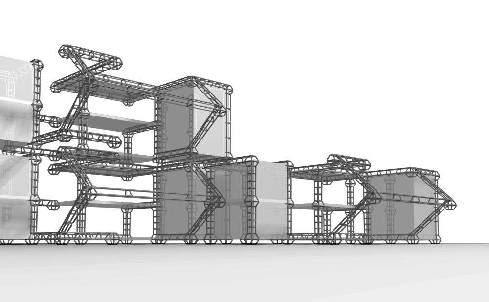
5 3. Results Our solid wireframe modeling method has been incorporated as an interactive tool into the three-dimensional mesh modeling system that we have developed [1, 2, 9]. Our system includes other features such as extrusions and re-meshing schemes, which when used in combination with the solid wireframe modeling tool, can create very interesting and complex shapes. The re-meshing schemes are particularly useful since they allows users to create several types of solid wireframe structures from the same initial mesh. Figure 4 shows an example of applying the solid wireframe modeling tool to a dodecahedron with different values of thickness and cross-sectional shape. As can be seen, increasing the number of sides in the cross-section of the pipes, produces smoother looking pipes. Having a smaller number of sides produces angular pipes. By varying the thickness we can create thin wire-like structures or thick pillar-like wireframes. Figure 4: The solid wireframe modeling tool applied to a dodecahedron with varying thickness and cross-section. The final model was created by applying the tool twice in succession. The solid wireframe modeling tool provides a simple, intuitive and easy-to-use interface for creating very complex structures in a few steps. It is well suited for use by architects and artists, and has been used to create conceptual models as well as stylized depictions of existing architectural models. Figure 5 shows an example of a model created using the solid wireframe modeling tool and its use in a conceptual sketch. Figure 6 shows a rendered model of a cathedral created using our new method. (A) (B) (C) Figure 5: Example of a frame structure created using the solid wireframe modeling tool. (A) shows the initial mesh and (B) shows the end result. (C) is a rendered image from a conceptual sketch (created by Ozan Ozener).

6 Figure 6: Model of a cathedral created using the column modeling tool. 4. Conclusions In this paper we have presented a new method for converting a regular wireframe mesh into a mesh in which the edges of the wireframe are replaced by cylindrical pipes of finite thickness and volume, a process we refer to as solidifying the wireframe. Our method allows users to create solid wireframes. The resulting model conveys 3D information about the object, including interior structures, much better than a traditional wireframe rendering or a surface rendering. Our algorithm works on any set of input edges they need not be connected to each other, nor do they have to represent a manifold surface. The fact that models created using our new tool can be fabricated (using 3D printers or rapid prototyping machines) is particularly pertinent for architects who want to create conceptual sketches and produce real 3D models from them. The tool has been used to create real and virtual environments, artistic depictions of known objects and architectural conceptual models. It can also be used to easily and quickly create complicated artistic shapes that would be difficult to generate using traditional modeling methods. Figures 7 and 8 show some more examples of conceptual design projects which make use of the solid wireframe modeling tool Our new method makes available a powerful tool for end users. However there is still room for improvement. For example, it would be useful if users could create spherical joints. This would add the ability to create models of molecules and other chemical structures, which when fabricated could be used as educational aids. Another useful addition would be the option to have symmetric but non-circular cross-sections, such as elliptical cross-sections, which are found in several engineering structures in the real world.

7 Figure 7: Conceptual work done using the column modeling tool. Design and modeling by Ozan Ozener. Figure 8: Conceptual work done using the column modeling tool. Design and modeling by Ozan Ozener.
8 References [1] AKLEMAN, E., CHEN, J., AND SRINIVASAN, V. An interactive shape modeling system for robust design of functional 3d shapes. In Proceedings of ACADIA 2001 (Oct. 2001), pp [2] AKLEMAN, E., CHEN, J., AND SRINIVASAN, V. A prototype system for robust, interactive and userfriendly modeling of orientable 2-manifold meshes. In Proceedings of Shape Modeling International 2002 (Banff, Canada, May 2002). [3] AKLEMAN, E., SRINIVASAN, V., AND CHEN, J. Interactive rind modeling. In Proceedings of Shape Modeling International 2003 (Seoul, Korea, May 2003). [4] CATMULL, E., AND CLARK, J. Recursively generated B-spline surfaces on arbitrary topological meshes. Computer Aided Design 10 (1978), [5] CATURANO, U., AND SANSEVERINO DI MARCELLINARA, C. Solid modelling by low-cost hardware and software: the crystal palace s node. In Proceedings of ecaade Conference (Eindhoven (The Netherlands), Nov. 1993). [6] DOO, D., AND SABIN, M. Behavior of recursive subdivision surfaces near extraordinary points. Computer Aided Design 10 (1978), [7] MANDAL, E. Wire and Column Modeling. Master s thesis, Texas A&M University, [8] MANDAL, E., SRINIVASAN, V., AND AKLEMAN, E. Wire modeling. SIGGRAPH 2003, Sketches and Applications, July [9] SRINIVASAN, V. Modeling High-Genus Surfaces. Ph.D. dissertation, Texas A&M University, [10] SRINIVASAN, V., AKLEMAN, E., AND CHEN, J. Interactive construction of multi-segment curved handles. Pacific Graphics 2002 (Oct. 2002). [11] VAN KEMPEN, A., KOK, H., AND WAGTER, H. Design modeling. Automation in Construction 1 (May 1992), [12] ZORIN, D., AND SCHRÖDER, P. Subdivision for modeling and animation. ACM SIGGRAPH 2000 Course Notes, 2000.
Modeling High Genus Sculptures Using Multi-Connected Handles and Holes
 Modeling High Genus Sculptures Using Multi-Connected Handles and Holes Vinod Srinivasan, Hernan Molina and Ergun Akleman Department of Architecture Texas A&M University College Station, Texas, USA vinod@viz.tamu.edu
Local Mesh Operators: Extrusions Revisited
 Local Mesh Operators: Extrusions Revisited Eric Landreneau Computer Science Department Abstract Vinod Srinivasan Visualization Sciences Program Texas A&M University Ergun Akleman Visualization Sciences
Interactive Rind Modeling for Architectural Design
 Interactive Rind Modeling for Architectural Design Ozan Önder Özener, Ergun Akleman and Vinod Srinivasan Visualization Sciences Program, Department of Architecture, Texas A&M University, USA http://viz.tamu.edu
On a Family of Symmetric, Connected and High Genus Sculptures
 On a Family of Symmetric, Connected and High Genus Sculptures Ergun Akleman and Cem Yuksel Visualization Sciences Program, Department of Architecture, College of Architecture emails: ergun@viz.tamu.edu,
On a Family of Symmetric, Connected and High Genus Sculptures
 On a Family of Symmetric, Connected and High Genus Sculptures E RGUN A KLEMAN O ZAN O ZENER C EM Y UKSEL Visualization Sciences Program, Department of Architecture Texas A&M University Abstract This paper
SEMIREGULAR PENTAGONAL SUBDIVISIONS
 SEMIREGULAR PENTAGONAL SUBDIVISIONS ERGUN AKLEMAN & VINOD SRINIVASAN Visualization Sciences Program Texas A&M University ZEKI MELEK & PAUL EDMUNDSON Computer Science Department Abstract Triangular and
Interactive and User-Friendly Construction of Multi-Segment Curved Handles
 Interactive and User-Friendly Construction of Multi-Segment Curved Handles VINOD SRINIVASAN Visualization Science Program Texas A&M University ERGUN AKLEMAN Visualization Science Program Texas A&M University
Honeycomb Subdivision
 Honeycomb Subdivision Ergun Akleman and Vinod Srinivasan Visualization Sciences Program, Texas A&M University Abstract In this paper, we introduce a new subdivision scheme which we call honeycomb subdivision.
Using Semi-Regular 4 8 Meshes for Subdivision Surfaces
 Using Semi-Regular 8 Meshes for Subdivision Surfaces Luiz Velho IMPA Instituto de Matemática Pura e Aplicada Abstract. Semi-regular 8 meshes are refinable triangulated quadrangulations. They provide a
Interactive Inverted Perspective Rendering for Architectural Visualization
 Interactive Inverted Perspective Rendering for Architectural Visualization Vinod Srinivasan Ozan Ozener Ergun Akleman 2005 June 20th 22nd Vienna University of Technology Vienna, Austria Visualization Sciences
Connected & Manifold Sierpinsky Polyhedra
 Volume xx (200y), Number z, pp. 1 6 Connected & Manifold Sierpinsky Polyhedra Vinod Srinivasan and Ergun Akleman Visualization Sciences Program, Department of Architecture, Texas A&M University Abstract
Tiled Textures What if Miro Had Painted a Sphere
 Tiled Textures What if Miro Had Painted a Sphere ERGUN AKLEMAN, AVNEET KAUR and LORI GREEN Visualization Sciences Program, Department of Architecture Texas A&M University December 26, 2005 Abstract We
From curves to surfaces. Parametric surfaces and solid modeling. Extrusions. Surfaces of revolution. So far have discussed spline curves in 2D
 From curves to surfaces Parametric surfaces and solid modeling CS 465 Lecture 12 2007 Doug James & Steve Marschner 1 So far have discussed spline curves in 2D it turns out that this already provides of
Local Modification of Subdivision Surfaces Based on Curved Mesh
 Local Modification of Subdivision Surfaces Based on Curved Mesh Yoshimasa Tokuyama Tokyo Polytechnic University tokuyama@image.t-kougei.ac.jp Kouichi Konno Iwate University konno@cis.iwate-u.ac.jp Junji
WIRE AND COLUMN MODELING
 WIRE AND COLUMN MODELING A Thesis by ESAN MANDAL Submitted to the Office of Graduate Studies of Texas A&M University in partial fulfillment of the requirements for the degree of MASTER OF SCIENCE May 2004
Subdivision Curves and Surfaces: An Introduction
 Subdivision Curves and Surfaces: An Introduction Corner Cutting De Casteljau s and de Boor s algorithms all use corner-cutting procedures. Corner cutting can be local or non-local. A cut is local if it
Technical Report. Removing polar rendering artifacts in subdivision surfaces. Ursula H. Augsdörfer, Neil A. Dodgson, Malcolm A. Sabin.
 Technical Report UCAM-CL-TR-689 ISSN 1476-2986 Number 689 Computer Laboratory Removing polar rendering artifacts in subdivision surfaces Ursula H. Augsdörfer, Neil A. Dodgson, Malcolm A. Sabin June 2007
Curve Corner Cutting
 Subdivision ision Techniqueses Spring 2010 1 Curve Corner Cutting Take two points on different edges of a polygon and join them with a line segment. Then, use this line segment to replace all vertices
u 0+u 2 new boundary vertex
 Combined Subdivision Schemes for the design of surfaces satisfying boundary conditions Adi Levin School of Mathematical Sciences, Tel-Aviv University, Tel-Aviv 69978, Israel. Email:fadilev@math.tau.ac.ilg
MA 323 Geometric Modelling Course Notes: Day 36 Subdivision Surfaces
 MA 323 Geometric Modelling Course Notes: Day 36 Subdivision Surfaces David L. Finn Today, we continue our discussion of subdivision surfaces, by first looking in more detail at the midpoint method and
1. Introduction. 2. Parametrization of General CCSSs. 3. One-Piece through Interpolation. 4. One-Piece through Boolean Operations
 Subdivision Surface based One-Piece Representation Shuhua Lai Department of Computer Science, University of Kentucky Outline. Introduction. Parametrization of General CCSSs 3. One-Piece through Interpolation
Subdivision Surfaces
 Subdivision Surfaces 1 Geometric Modeling Sometimes need more than polygon meshes Smooth surfaces Traditional geometric modeling used NURBS Non uniform rational B-Spline Demo 2 Problems with NURBS A single
Lecture 17: Solid Modeling.... a cubit on the one side, and a cubit on the other side Exodus 26:13
 Lecture 17: Solid Modeling... a cubit on the one side, and a cubit on the other side Exodus 26:13 Who is on the LORD's side? Exodus 32:26 1. Solid Representations A solid is a 3-dimensional shape with
TopMod3D. An Interactive Topological Mesh Modeler. Computer Graphics International manuscript No. (will be inserted by the editor)
") Computer Graphics International manuscript No. (will be inserted by the editor) Ergun Akleman Vinod Srinivasan Jianer Chen David Victor Morris Stuart Tosten Tett TopMod3D An Interactive Topological Mesh
Computer Graphics International manuscript No. (will be inserted by the editor) Ergun Akleman Vinod Srinivasan Jianer Chen David Victor Morris Stuart Tosten Tett TopMod3D An Interactive Topological Mesh
Subdivision Surfaces. Homework 1: Questions on Homework? Last Time? Today. Tensor Product. What s an illegal edge collapse?
 Homework 1: Questions/Comments? Subdivision Surfaces Questions on Homework? Last Time? What s an illegal edge collapse? Curves & Surfaces Continuity Definitions 2 3 C0, G1, C1, C 1 a b 4 Interpolation
Subdivision Surfaces. Homework 1: Questions/Comments?
 Subdivision Surfaces Homework 1: Questions/Comments? 1 Questions on Homework? What s an illegal edge collapse? 1 2 3 a b 4 7 To be legal, the ring of vertex neighbors must be unique (have no duplicates)!
Geometric Modeling. Introduction
 Geometric Modeling Introduction Geometric modeling is as important to CAD as governing equilibrium equations to classical engineering fields as mechanics and thermal fluids. intelligent decision on the
A Minimal and Complete Set of Operators for the Development of Robust Manifold Mesh Modelers
 A Minimal and Complete Set of Operators for the Development of Robust Manifold Mesh Modelers Ergun Akleman a,1,, Jianer Chen b, Vinod Srinivasan c a Visualization Laboratory, 216 Langford Center, Texas
Subdivision Surfaces
 Subdivision Surfaces 1 Geometric Modeling Sometimes need more than polygon meshes Smooth surfaces Traditional geometric modeling used NURBS Non uniform rational B-Spline Demo 2 Problems with NURBS A single
CS354 Computer Graphics Surface Representation IV. Qixing Huang March 7th 2018
 CS354 Computer Graphics Surface Representation IV Qixing Huang March 7th 2018 Today s Topic Subdivision surfaces Implicit surface representation Subdivision Surfaces Building complex models We can extend
EXACT FACE-OFFSETTING FOR POLYGONAL MESHES
 5.0 GEOMIMESIS/LANDFORMING HAMBLETON + ROSS EXACT FACE-OFFSETTING FOR POLYGONAL MESHES Elissa Ross MESH Consultants Inc. Daniel Hambleton MESH Consultants Inc. ABSTRACT Planar-faced mesh surfaces such
3D Modeling techniques
 3D Modeling techniques 0. Reconstruction From real data (not covered) 1. Procedural modeling Automatic modeling of a self-similar objects or scenes 2. Interactive modeling Provide tools to computer artists
Subdivision overview
 Subdivision overview CS4620 Lecture 16 2018 Steve Marschner 1 Introduction: corner cutting Piecewise linear curve too jagged for you? Lop off the corners! results in a curve with twice as many corners
Robustness of Boolean operations on subdivision-surface models
 Robustness of Boolean operations on subdivision-surface models Di Jiang 1, Neil Stewart 2 1 Université de Montréal, Dép t. Informatique CP6128, Succ. CentreVille, Montréal, H3C 3J7, Qc, Canada jiangdi@umontreal.ca
SURFACE FAIRING FOR SHIP HULL DESIGN
 SURFACE FAIRING FOR SHIP HULL DESIGN Xoán A. Leiceaga Eva Soto GED, Universidad de Vigo, Vigo, España leiceaga@uvigo.es Oscar E. Ruiz Carlos A. Vanegas Laboratorio CAD/CAM/CAE, Universidad EAFIT, Medellín,
Key 3D Modeling Terms Beginners Need To Master
 Key 3D Modeling Terms Beginners Need To Master Starting your 3D modeling journey is an exciting and rewarding experience. As you begin to learn and practice, there are essential terms you need to know
Modeling a Scanned Object with RapidWorks
 Modeling a Scanned Object with RapidWorks RapidWorks allows you to use a scanned point cloud of an object from the NextEngine Desktop 3D Scanner to create a CAD representation of an object. This guide
Physically-Based Modeling and Animation. University of Missouri at Columbia
 Overview of Geometric Modeling Overview 3D Shape Primitives: Points Vertices. Curves Lines, polylines, curves. Surfaces Triangle meshes, splines, subdivision surfaces, implicit surfaces, particles. Solids
Interactive Deformation with Triangles
 Interactive Deformation with Triangles James Dean Palmer and Ergun Akleman Visualization Sciences Program Texas A&M University Jianer Chen Department of Computer Science Texas A&M University Abstract In
Computer Graphics Prof. Sukhendu Das Dept. of Computer Science and Engineering Indian Institute of Technology, Madras Lecture - 24 Solid Modelling
 Computer Graphics Prof. Sukhendu Das Dept. of Computer Science and Engineering Indian Institute of Technology, Madras Lecture - 24 Solid Modelling Welcome to the lectures on computer graphics. We have
Character Modeling COPYRIGHTED MATERIAL
 38 Character Modeling p a r t _ 1 COPYRIGHTED MATERIAL 39 Character Modeling Character Modeling 40 1Subdivision & Polygon Modeling Many of Maya's features have seen great improvements in recent updates
Computergrafik. Matthias Zwicker Universität Bern Herbst 2016
 Computergrafik Matthias Zwicker Universität Bern Herbst 2016 Today Curves NURBS Surfaces Parametric surfaces Bilinear patch Bicubic Bézier patch Advanced surface modeling 2 Piecewise Bézier curves Each
L1 - Introduction. Contents. Introduction of CAD/CAM system Components of CAD/CAM systems Basic concepts of graphics programming
 L1 - Introduction Contents Introduction of CAD/CAM system Components of CAD/CAM systems Basic concepts of graphics programming 1 Definitions Computer-Aided Design (CAD) The technology concerned with the
Design by Subdivision
 Bridges 2010: Mathematics, Music, Art, Architecture, Culture Design by Subdivision Michael Hansmeyer Department for CAAD - Institute for Technology in Architecture Swiss Federal Institute of Technology
Caricaturing Buildings for Effective Visualization
 Caricaturing Buildings for Effective Visualization Grant G. Rice III, Ergun Akleman, Ozan Önder Özener and Asma Naz Visualization Sciences Program, Department of Architecture, Texas A&M University, USA
Solid Modeling. Ron Goldman Department of Computer Science Rice University
 Solid Modeling Ron Goldman Department of Computer Science Rice University Solids Definition 1. A model which has a well defined inside and outside. 2. For each point, we can in principle determine whether
Introduction to ANSYS DesignModeler
 Lecture 9 Beams and Shells 14. 5 Release Introduction to ANSYS DesignModeler 2012 ANSYS, Inc. November 20, 2012 1 Release 14.5 Beams & Shells The features in the Concept menu are used to create and modify
12.3 Subdivision Surfaces. What is subdivision based representation? Subdivision Surfaces
 2.3 Subdivision Surfaces What is subdivision based representation? Subdivision Surfaces Multi-resolution (Scalability) One piece representation (arbitrary topology) What is so special? Numerical stability
Handles. The justification: For a 0 genus triangle mesh we can write the formula as follows:
 Handles A handle in a 3d mesh is a through hole. The number of handles can be extracted of the genus of the 3d mesh. Genus is the number of times we can cut 2k edges without disconnecting the 3d mesh.
Computergrafik. Matthias Zwicker. Herbst 2010
 Computergrafik Matthias Zwicker Universität Bern Herbst 2010 Today Curves NURBS Surfaces Parametric surfaces Bilinear patch Bicubic Bézier patch Advanced surface modeling Piecewise Bézier curves Each segment
Until now we have worked with flat entities such as lines and flat polygons. Fit well with graphics hardware Mathematically simple
 Curves and surfaces Escaping Flatland Until now we have worked with flat entities such as lines and flat polygons Fit well with graphics hardware Mathematically simple But the world is not composed of
Subdivision Surfaces. Homework 1: Last Time? Today. Bilinear Patch. Tensor Product. Spline Surfaces / Patches
 Homework 1: Questions/Comments? Subdivision Surfaces Last Time? Curves & Surfaces Continuity Definitions Spline Surfaces / Patches Tensor Product Bilinear Patches Bezier Patches Trimming Curves C0, G1,
Physically-Based Laser Simulation
 Physically-Based Laser Simulation Greg Reshko Carnegie Mellon University reshko@cs.cmu.edu Dave Mowatt Carnegie Mellon University dmowatt@andrew.cmu.edu Abstract In this paper, we describe our work on
Curves and Surfaces 2
 Curves and Surfaces 2 Computer Graphics Lecture 17 Taku Komura Today More about Bezier and Bsplines de Casteljau s algorithm BSpline : General form de Boor s algorithm Knot insertion NURBS Subdivision
Topology and Boundary Representation. The ACIS boundary representation (B-rep) of a model is a hierarchical decomposition of the model s topology:
 of a model is a hierarchical decomposition of the model s topology:") Chapter 6. Model Topology Topology refers to the spatial relationships between the various entities in a model. Topology describes how geometric entities are connected (connectivity). On its own, topology
Chapter 6. Model Topology Topology refers to the spatial relationships between the various entities in a model. Topology describes how geometric entities are connected (connectivity). On its own, topology
Surfaces for CAGD. FSP Tutorial. FSP-Seminar, Graz, November
 Surfaces for CAGD FSP Tutorial FSP-Seminar, Graz, November 2005 1 Tensor Product Surfaces Given: two curve schemes (Bézier curves or B splines): I: x(u) = m i=0 F i(u)b i, u [a, b], II: x(v) = n j=0 G
Chapter 2: Rhino Objects
 The fundamental geometric objects in Rhino are points, curves, surfaces, polysurfaces, extrusion objects, and polygon mesh objects. Why NURBS modeling NURBS (non-uniform rational B-splines) are mathematical
arxiv:cs/ v1 [cs.cg] 13 Jun 2001
![arxiv:cs/ v1 [cs.cg] 13 Jun 2001](/thumbs/80/81425240.jpg "arxiv:cs/ v1 [cs.cg] 13 Jun 2001") Hinged Kite Mirror Dissection David Eppstein arxiv:cs/0106032v1 [cs.cg] 13 Jun 2001 Abstract Any two polygons of equal area can be partitioned into congruent sets of polygonal pieces, and in many cases
Hinged Kite Mirror Dissection David Eppstein arxiv:cs/0106032v1 [cs.cg] 13 Jun 2001 Abstract Any two polygons of equal area can be partitioned into congruent sets of polygonal pieces, and in many cases
Offset Triangular Mesh Using the Multiple Normal Vectors of a Vertex
 285 Offset Triangular Mesh Using the Multiple Normal Vectors of a Vertex Su-Jin Kim 1, Dong-Yoon Lee 2 and Min-Yang Yang 3 1 Korea Advanced Institute of Science and Technology, sujinkim@kaist.ac.kr 2 Korea
3 Polygonal Modeling. Getting Started with Maya 103
 3 Polygonal Modeling In Maya, modeling refers to the process of creating virtual 3D surfaces for the characters and objects in the Maya scene. Surfaces play an important role in the overall Maya workflow
3D Modeling and Design Glossary - Beginner
 3D Modeling and Design Glossary - Beginner Align: to place or arrange (things) in a straight line. To use the Align tool, select at least two objects by Shift left-clicking on them or by dragging a box
Homework 1: Implicit Surfaces, Collision Detection, & Volumetric Data Structures. Loop Subdivision. Loop Subdivision. Questions/Comments?
 Homework 1: Questions/Comments? Implicit Surfaces,, & Volumetric Data Structures Loop Subdivision Shirley, Fundamentals of Computer Graphics Loop Subdivision SIGGRAPH 2000 course notes Subdivision for
Chapter 12 Solid Modeling. Disadvantages of wireframe representations
 Chapter 12 Solid Modeling Wireframe, surface, solid modeling Solid modeling gives a complete and unambiguous definition of an object, describing not only the shape of the boundaries but also the object
Femap v11.2 Geometry Updates
 Femap v11.2 Geometry Updates Chip Fricke, Femap Principal Applications Engineer chip.fricke@siemens.com Femap Symposium Series 2015 June, 2015 Femap Symposium Series 2015 Femap v11.2 Geometry Creation
The goal is the definition of points with numbers and primitives with equations or functions. The definition of points with numbers requires a
 The goal is the definition of points with numbers and primitives with equations or functions. The definition of points with numbers requires a coordinate system and then the measuring of the point with
Regular Meshes. Abstract. 1 Introduction. JIANER CHEN Computer Science Department. ERGUN AKLEMAN Visualization Sciences Program. Texas A&M University
 ERGUN AKLEMAN Visualization Sciences Program Regular Meshes Texas A&M University JIANER CHEN Computer Science Department Abstract This paper presents our preliminary results on regular meshes in which
Porsche 91 1GT D m o d e ling tutorial - by Nim
 orsche 911GT 3D modeling tutorial - by Nimish In this tutorial you will learn to model a car using Spline modeling method. This method is not very much famous as it requires considerable amount of skill
Subdivision Surfaces. Course Syllabus. Course Syllabus. Modeling. Equivalence of Representations. 3D Object Representations
 Subdivision Surfaces Adam Finkelstein Princeton University COS 426, Spring 2003 Course Syllabus I. Image processing II. Rendering III. Modeling IV. Animation Image Processing (Rusty Coleman, CS426, Fall99)
Subdivision surfaces. University of Texas at Austin CS384G - Computer Graphics Fall 2010 Don Fussell
 Subdivision surfaces University of Texas at Austin CS384G - Computer Graphics Fall 2010 Don Fussell Reading Recommended: Stollnitz, DeRose, and Salesin. Wavelets for Computer Graphics: Theory and Applications,
MODERN DESCRIPTIVE GEOMETRY SUPPORTED BY 3D COMPUTER MODELLING
 International Conference on Mathematics Textbook Research and Development 2014 () 29-31 July 2014, University of Southampton, UK MODERN DESCRIPTIVE GEOMETRY SUPPORTED BY 3D COMPUTER MODELLING Petra Surynková
SEOUL NATIONAL UNIVERSITY
 Fashion Technology 5. 3D Garment CAD-1 Sungmin Kim SEOUL NATIONAL UNIVERSITY Overview Design Process Concept Design Scalable vector graphics Feature-based design Pattern Design 2D Parametric design 3D
Joe Warren, Scott Schaefer Rice University
 Joe Warren, Scott Schaefer Rice University Polygons are a ubiquitous modeling primitive in computer graphics. Their popularity is such that special purpose graphics hardware designed to render polygons
Non-Uniform Recursive Doo-Sabin Surfaces
 Non-Uniform Recursive Doo-Sabin Surfaces Zhangjin Huang a,b,c,, Guoping Wang d,e a School of Computer Science and Technology, University of Science and Technology of China, PR China b Key Laboratory of
Approximating Catmull-Clark Subdivision Surfaces with Bicubic Patches
 Approximating Catmull-Clark Subdivision Surfaces with Bicubic Patches Charles Loop Microsoft Research Scott Schaefer Texas A&M University April 24, 2007 Technical Report MSR-TR-2007-44 Microsoft Research
Convex Hulls in Three Dimensions. Polyhedra
 Convex Hulls in Three Dimensions Polyhedra Polyhedron 1.A polyhedron is the generalization of a 2- D polygon to 3-D A finite number of flat polygonal faces The boundary or surface of a polyhedron - Zero-dimensional
Procedural Articulation of Form
 R. Stouffs, P. Janssen, S. Roudavski, B. Tunçer (eds.), Open Systems: Proceedings of the 18th International Conference on Computer-Aided Architectural Design Research in Asia (CAADRIA 2013), 821 829. 2013,
ERC Expressive Seminar
 ERC Expressive Seminar March 7th - 2013 Models and Intuitive Modeling Loïc Barthe VORTEX group IRIT Université de Toulouse Plan Context and introduction Intuitive modeling Modeling with meshes only Other
Constructing treatment features
 Constructing treatment features Publication Number spse01530 Constructing treatment features Publication Number spse01530 Proprietary and restricted rights notice This software and related documentation
Non-Uniform Recursive Doo-Sabin Surfaces (NURDSes)
") Non-Uniform Recursive Doo-Sabin Surfaces Zhangjin Huang 1 Guoping Wang 2 1 University of Science and Technology of China 2 Peking University, China SIAM Conference on Geometric and Physical Modeling Doo-Sabin
Non-Uniform Recursive Doo-Sabin Surfaces Zhangjin Huang 1 Guoping Wang 2 1 University of Science and Technology of China 2 Peking University, China SIAM Conference on Geometric and Physical Modeling Doo-Sabin
Near-Optimum Adaptive Tessellation of General Catmull-Clark Subdivision Surfaces
 Near-Optimum Adaptive Tessellation of General Catmull-Clark Subdivision Surfaces Shuhua Lai and Fuhua (Frank) Cheng (University of Kentucky) Graphics & Geometric Modeling Lab, Department of Computer Science,
Dgp _ lecture 2. Curves
 Dgp _ lecture 2 Curves Questions? This lecture will be asking questions about curves, their Relationship to surfaces, and how they are used and controlled. Topics of discussion will be: Free form Curves
Free-Form Deformation with Automatically Generated Multiresolution Lattices
 Free-Form Deformation with Automatically Generated Multiresolution Lattices Yutaka Ono* Bing-Yu Chen* Tomoyuki Nishita* Jieqing Feng *The University of Tokyo Zhejang University {yutaka-o, robin, nis}@is.s.u-tokyo.ac.jp
Removing Polar Rendering Artifacts in Subdivision Surfaces
 This is an electronic version of an article published in Journal of Graphics, GPU, and Game Tools, Volume 14, Issue 2 pp. 61-76, DOI: 10.1080/2151237X.2009.10129278. The Journal of Graphics, GPU, and Game
Multimaterial Geometric Design Theories and their Applications
 Multimaterial Geometric Design Theories and their Applications Hong Zhou, Ph.D. Associate Professor Department of Mechanical Engineering Texas A&M University-Kingsville October 19, 2011 Contents Introduction
Regular Mesh Construction Algorithms using Regular Handles
 Regular Mesh Construction Algorithms using Regular Handles Ergun Akleman Visualization Sciences Program Texas A&M University Jianer Chen Computer Science Department Abstract This paper presents our recent
Recursive Subdivision Surfaces for Geometric Modeling
 Recursive Subdivision Surfaces for Geometric Modeling Weiyin Ma City University of Hong Kong, Dept. of Manufacturing Engineering & Engineering Management Ahmad Nasri American University of Beirut, Dept.
 Orientable Closed/ Boundary-less 2-manifold This wireframe study of a chalice was painted by the Italian Renaissance artist Paolo Uccello around 1460. Today 3D polygonal meshes are the dominant representation
Computer Aided Engineering Design Prof. Anupam Saxena Department of Mechanical Engineering Indian Institute of Technology, Kanpur.
 (Refer Slide Time: 00:28) Computer Aided Engineering Design Prof. Anupam Saxena Department of Mechanical Engineering Indian Institute of Technology, Kanpur Lecture - 6 Hello, this is lecture number 6 of
Triangle meshes I. CS 4620 Lecture Steve Marschner. Cornell CS4620 Spring 2017
 Triangle meshes I CS 4620 Lecture 2 2017 Steve Marschner 1 spheres Andrzej Barabasz approximate sphere Rineau & Yvinec CGAL manual 2017 Steve Marschner 2 finite element analysis PATRIOT Engineering 2017
Multi-View Matching & Mesh Generation. Qixing Huang Feb. 13 th 2017
 Multi-View Matching & Mesh Generation Qixing Huang Feb. 13 th 2017 Geometry Reconstruction Pipeline RANSAC --- facts Sampling Feature point detection [Gelfand et al. 05, Huang et al. 06] Correspondences
Autodesk Inventor 6 Essentials Instructor Guide Chapter Four: Creating Placed Features Chapter Outline This chapter provides instruction on the follow
 Chapter Four: Creating Placed Features Chapter Outline This chapter provides instruction on the following topics and provides exercises for students to practice their skills. Day Two Topic: How to create
Saab. Kyle McDonald. Polygon Meshes
 Saab Kyle McDonald Polygon Meshes Siddhartha Chaudhuri http://www.cse.iitb.ac.in/~cs749 What is a polygon mesh? Like a point cloud, it is a discrete sampling of a surface... but, it adds linear (flat)
Spatial Data Structures
 15-462 Computer Graphics I Lecture 17 Spatial Data Structures Hierarchical Bounding Volumes Regular Grids Octrees BSP Trees Constructive Solid Geometry (CSG) April 1, 2003 [Angel 9.10] Frank Pfenning Carnegie
Using Perspective Rays and Symmetry to Model Duality
 Using Perspective Rays and Symmetry to Model Duality Alex Wang Electrical Engineering and Computer Sciences University of California at Berkeley Technical Report No. UCB/EECS-2016-13 http://www.eecs.berkeley.edu/pubs/techrpts/2016/eecs-2016-13.html
Image Morphing. The user is responsible for defining correspondences between features Very popular technique. since Michael Jackson s clips
 Image Morphing Image Morphing Image Morphing Image Morphing The user is responsible for defining correspondences between features Very popular technique since Michael Jackson s clips Morphing Coordinate
Critique for CS 448B: Topics in Modeling The Voronoi-clip Collision Detection Algorithm
 Critique for CS 448B: Topics in Modeling The Voronoi-clip Collision Detection Algorithm 1. Citation Richard Bragg March 3, 2000 Mirtich B. (1997) V-Clip: Fast and Robust Polyhedral Collision Detection.
coding of various parts showing different features, the possibility of rotation or of hiding covering parts of the object's surface to gain an insight
 Three-Dimensional Object Reconstruction from Layered Spatial Data Michael Dangl and Robert Sablatnig Vienna University of Technology, Institute of Computer Aided Automation, Pattern Recognition and Image
Triangle meshes I. CS 4620 Lecture 2
 Triangle meshes I CS 4620 Lecture 2 2014 Steve Marschner 1 spheres Andrzej Barabasz approximate sphere Rineau & Yvinec CGAL manual 2014 Steve Marschner 2 finite element analysis PATRIOT Engineering 2014
3D Modeling: Surfaces
 CS 430/536 Computer Graphics I 3D Modeling: Surfaces Week 8, Lecture 16 David Breen, William Regli and Maxim Peysakhov Geometric and Intelligent Computing Laboratory Department of Computer Science Drexel
An Efficient Data Structure for Representing Trilateral/Quadrilateral Subdivision Surfaces
 BULGARIAN ACADEMY OF SCIENCES CYBERNETICS AND INFORMATION TECHNOLOGIES Volume 3, No 3 Sofia 203 Print ISSN: 3-9702; Online ISSN: 34-408 DOI: 0.2478/cait-203-0023 An Efficient Data Structure for Representing