13 Advanced Rendering and Illumination Methods Advanced Rendering and Illumination Methods
|
|
|
- William Hoover
- 6 years ago
- Views:
Transcription
1 Chapter 13 Advanced Rendering and Illumination Methods 13-1
2 Objectives What are shaders? Introduce programmable pipelines Vertex shaders Fragment shaders Introduce shading languages Needed to write shaders OpenGL Shading Language (GLSL) 13-2
3 Programmable Pipeline Recent major advance in real time graphics is programmable pipeline First introduced by NVIDIA GForce 3 (2001) Supported by high-end commodity cards NVIDIA, ATI, 3D Labs Software Support Direct X 8 and up OpenGL Extensions OpenGL Shading Language (GLSL) Cg CUDA OpenCL 13-3
 Vertex")

 Assembly & Rasterization")


4 Programmable Graphics Pipeline Graphics State Application CPU Note: Vertices (3D) Vertex Processor Vertex processor does all transform and lighting Pipe widths vary Intra-GPU pipes wider than CPU GPU pipe Thin GPU CPU pipe transformed, Lit Vertices (2D) Assembly & Rasterization Fragments (pre-pixels) Fragment Pixel Processor GPU Here s what s cool: Final pixels (Color, Depth) Render-to-texture Can now program vertex processor! Can now program fragment processor! Video Memory (Textures) CS

5 GLSL: Back to the future OpenGL does not provide a programming language. Its function may be controlled by turning operations on or off or specifying parameters to operations, but the rendering algorithms are essentially fixed. One reason for this decision is that, for performance reasons, graphics hardware is usually designed to apply certain operations in a specific order; replacing these operations with arbitrary algorithms is usually infeasible. Programmability Segal and Akeley, would The Design conflict of with the OpenGL keeping the Graphics API close Interface, to the hardware 1994 and thus with the August goal 23, of 1993: maximum First OpenGL performance. 1.0 implementation 13-5
6 Present-Shaders OpenGL version 2.0 What are Shaders? Shaders are programs running on vertex processor (vertex shader) and/or fragment processor (fragment shader) that replace the fixed functionalities of OpenGL pipeline. Can replace either or both If we use a programmable shader we must do all required functions of the fixed function processor 13-6
7 Shaders Written using GPU language Low-level: assembly language High-level: Cg, GLSL, CUDA, OpenCL Run on GPU while the application runs at the same time on CPU GPU is often parallel: SIMD (single instruction multiple data) GPU is much faster than CPU Use GPU for other computations other than Graphics 13-7
8 Vertex Shader A vertex shader should replace the geometric calculations on vertices in the fixed pipeline Per-vertex data (x,y,z,w) coordinates of a vertex (glvertex) Normal vector Texture Coordinates RGBA color Other data: color indices, edge flags Additional user-defined data in GLSL Per-vertex operations transformed by the model-view and projection matrix. Note normal is transformed by the inverse-transpose of the MV matrix Per vertex lighting computation 13-9
9 Vertex Shader Applications Moving vertices Morphing Wave motion Fractals Particle systems Lighting More realistic lighting models Cartoon shaders 13-10


10 6 Color Models and Color Applications Primitive Assembly and Rasterization Vertices are next assembled into objects: Points, Line Segments, and Polygons Clipped and mapped to the viewport Geometric entities are rasterized into fragments Each fragment is a potential pixel Each fragment has attributes such as A color Possibly a depth value Texture coordinates 6-11
11 Fragment Shader Takes in fragments from the rasterizer Vertex values have been interpolated over primitive by rasterizer Perform fragment operations, such as texture mapping, fog, antialiasing, Scissoring, and Blending etc. Outputs a fragment Color Depth-value Fragments still go through fragment tests alpha test Depth test 13-12
12 Fragment Shader Applications Per fragment lighting calculations per vertex lighting per fragment lighting 13-13


13 Fragment Shader Applications Texture mapping smooth shading bump mapping 13-14
14 Writing Shaders First programmable shaders were programmed in an assembly-like manner OpenGL extensions added for vertex and fragment shaders Cg (C for graphics) C-like language for programming shaders Works with both OpenGL and DirectX Interface to OpenGL complex OpenGL Shading Language (GLSL) became part of OpenGL 2.0 standard 13-15
15 Shading Language History RenderMan Shading Language (1988) Offline rendering Hardware Shading Languages UNC, Stanford (1998, 2001) NVIDIA (2002) OpenGL Vertex Program Extension OpenGL Shading Language (2004) Cg and Microsoft HLSL (2002) 13-16
16 GLSL Part of OpenGL 2.0 High level C-like language, but different New data types Matrices Vectors Samplers Built-in variables and functions Each shader has a main() function as the entrance point. Compiler built into driver Presumably they know your card best IHV s must produce (good) compilers 13-17
17 Simplest Vertex Shader const vec4 red = vec4(1.0, 0.0, 0.0, 1.0); void main(void) { } gl_position = ftransform(); gl_frontcolor = red; 13-18

18 Vertex Shader 6 Color Models and Color Applications Input to a vertex shader? Per vertex attributes: e.g. glvertex, gl_normal, gl_color,, and user defined. OpenGL states and user defined uniform variables Output from a vertex shader gl_position: coordinates in the canonic space Other values to be interpolated during rasterization into fragment values, e.g. gl_frontcolor 6-19

19 6 Color Models and Color Applications Fragment Shader Execution Model Input to a fragment shader Interpolated values from the rasterizer OpenGL states and user defined uniform variables Output of a fragment shader Pixel values to be processed by pixel tests and written to the frame buffer, e.g. gl_fragcolor, gl_fragdepth 6-20
20 GLSL Data Types scalar types: int, float, bool No implicit conversion between types Vectors: Float: vec2, vec3, vec4 Also int: ivec and bool: bvec C++ style constructors vec3 a = vec3(1.0, 2.0, 3.0) vec2 b = vec2(a) Matrices (only float) : mat2, mat3, mat4 Stored by columns order (OpenGL convention) mat2 m = mat2(1.0, 2.0, 3.0, 4.0); Standard referencing m[column][row] What is the value of m[0][1]? 13-21
21 GLSL Sampler Types Sampler types are used to represent textures, which may be used in both vertex and fragment shader samplernd sampler1d, sampler2d, sampler3d samplercube sampler1dshadow, sampler2dshadow 13-22
22 Arrays and Structs GLSL can have arrays float x[4]; vec3 colors[5]; colors[0] = vec3(1.0, 1.0, 0.0); mat4 matrices[3]; Only one-dimensional array and size is an integral constant GLSL also have C-like structs struct light { } vec4 position; vec3 color; There are no pointers in GLSL 13-23
23 GLSL scope of variables global Outside function Vertex and fragment shader may share global variables that must have the same types and names. Local Within function definition Within a function Because matrices and vectors are basic types they can be passed into and output from GLSL functions, e.g. matrix3 func(matrix3 a) 13-24
24 Operators Matrix multiplication is implemented using * operator mat4 m4, n4; vec4 v4; m4 * v4 // a vec4 v4 * m4 // a vec4 m4 * n4 // a mat
25 Swizzling and Selection Can refer to vector or matrix elements by element using [ ] operator or selection (.) operator with x, y, z, w r, g, b, a s, t, p, q vec v4 = (1.0, 2.0, 3.0, 4.0); v4[2], v4.b, v4.z, v4.p are the same What are v4.xy, v4.rga, v4.zzz? Swizzling operator lets us manipulate components vec4 a; a.yz = vec2(1.0, 2.0); a.zz = vec2(2.0, 4.0); Is it correct? 13-26
26 GLSL Qualifiers GLSL has many of the same qualifiers such as const as C/C++ The declaration is of a compile time constant Need others due to the nature of the execution model attribute uniform varying Qualifiers used for function calls in, out, inout 13-27
27 Functions User-defined function call by value-return Variables are copied in, Returned values are copied back Function overload Three possibilities for parameters in out inout vec4 func1 (float f); // in qualifier is implicit void func2(out float f) { f = 0.1; } // f is used to copy values out of the function call void func3(inout float f) { f *= 2.0; } // f is used to copy values in and out of the function 13-28
28 Built-in Functions Trigonometry sin, cos, tan, asin, acos, atan, Exponential pow, exp2, log2, sqrt, inversesqrt Common abs, floor, sign, ceil, min, max, clamp, Geometric length, dot, cross, normalize, reflect, distance, Texture lookup texture1d texture2d, texture3d, texturecube, Noise functions ftransform: transform vertex coordinates to clipping space by modelview and projection matrices
29 Attribute Qualifier Global variables that change per vertex Only are used in vertex shaders and read-only. Pass values from the application to vertex shaders. Number is limited, e.g. 32 (hardware-dependent) Examples: Built in (OpenGL state variables) gl_vertex gl_color gl_normal gl_secondarycolor gl_multitexcoordn gl_fogcoord User defined in vertex shader attribute float temperature; attribute vec3 velocity; 13-30
30 Uniform Qualifier Global variables that change less often, e.g. per primitive or object May be used in both vertex and fragment shader Read-only passed from the OpenGL application to the shaders. may not be set inside glbegin and glend block Number is limited, but a lot more than attribute variables Built-in uniforms uniform mat4 gl_modelviewmatrix; uniform mat4 gl_projectionmatrix; uniform mat4 gl_modelviewprojectionmatrix; uniform mat4 gl_texturematrix[n]; Uniform mat3 gl_normalmatrix; // inverse transpose modlview matrix 13-31
31 Uniforms Built-in uniforms uniform gl_lightsourceparameters gl_lightsource[gl_maxlights]; gl_lightsourceparameters is a built-in struct describing OpenGL light sources User-defined uniforms Used to pass information to shader such as the bounding box of a primitive Example: uniform float mycurrenttime; uniform vec4 myambient; 13-32
32 Varying Qualifier Used for passing interpolated data between a vertex shader and a fragment shader. Available for writing in the vertex shader read-only in a fragment shader. Automatically interpolated by the rasterizer Built in Vertex colors: varying vec4 gl_frontcolor; // vertex varying vec4 gl_backcolor; // vertex varying vec4 gl_color; // fragment Texture coordinates: varying vec4 gl_texcoord[];//both User defined varying variables Requires a matching definition in the vertex and fragment shader For example varying vec3 normal can be used for per-pixel lighting 13-33
33 Built-in output types There are also built-in types available that are used as the output of the shader programs: glposition gl_fragcolor gl_fragdepth 4D vector representing the final processed vertex position (only available in vertex shader) 4D vector representing the final color which is written in the frame buffer (only available in fragment shader) float representing the depth which is written in the depth buffer (only available in fragment shader) 13-34
34 Use GLSL Shaders 1. Create shader object Gluint S = glcreateshader(gl_vertex_shader) Vertex or Fragment 2. Load shader source code into object glshadersource(s, n, shaderarray, lenarray) Array of strings 3. Compile shaders glcompileshader(s) 13-35
35 Loading Shaders glshadersource(s, n, shaderarray, lenarray) n the number of strings in the array Strings as lines Null-terminated if lenarray is Null or length=-1 Example const GLchar* vsource = readfile( shader.vert ); glshadersource(s, 1, &vsource, NULL); 13-36
36 Use GLSL Shaders 4. Create program object GLuint P = glcreateprogram() 5. Attach all shader objects glattachshader(p, S) Vertex, Fragment or both 6. Link together gllinkprogram(p) 7. Use gluseprogram(p) In order to use fixed OpenGL functionality, call gluseprogram with value 0; 13-37
37 Set attribute/uniform values We need to pass vertex attributes to the vertex shader Vertex attributes are named in the shaders Linker forms a table Application can get index from table Similar process for uniform variables Where is my attributes/uniforms parameter? Find them in the application GLint i =glgetattriblocation(p, myattrib ) GLint j =glgetuniformlocation(p, myuniform ) Set them glvertexattrib1f(i,value) gluniform1f(j,value) glvertexattribpointer(i, ) // passing attributes using vertex array 13-38
38 Older OpenGL versions If your computer has an older OpenGL version (typically the case on Windows) you will have to use the ARB calls. In Windows, you will have to get the procedure addresses similar to what was necessary for the VBO function calls, for example: PFNGLSHADERSOURCEARBPROC glshadersourcearb; glshadersourcearb = (PFNGLSHADERSOURCEARBPROC)wglGetProcAddress( "glshadersourcearb"); 13-39
39 Use GLSL Shaders 1. Create shader object Gluint S = glcreateshaderarb(gl_vertex_shader) Vertex or Fragment 2. Load shader source code into object glshadersourcearb(s, n, shaderarray, lenarray) Array of strings 3. Compile shaders glcompileshaderarb(s) 13-40
40 Loading Shaders glshadersourcearb(s, n, shaderarray, lenarray) n the number of strings in the array Strings as lines Null-terminated if lenarray is Null or length=-1 Example const GLchar* vsource = readfile( shader.vert ); glshadersourcearb(s, 1, &vsource, NULL); 13-41
41 Use GLSL Shaders 4. Create program object P = glcreateprogram() 5. Attach all shader objects glattachshaderarb(p, S) or glattachobjectarb (P) glattachobjectarb (S) Vertex, Fragment or both 6. Link together gllinkprogramarb(p) 7. Use gluseprogramarb(p) In order to use fixed OpenGL functionality, call gluseprogramarb with value 0; 13-42
42 Example 1: Trivial Vertex Shader varying vec3 Normal; void main(void) { } gl_position = ftransform() ; Normal = normalize(gl_normalmatrix * gl_normal); gl_frontcolor = gl_color; 13-43
43 Trivial Fragment Shader varying vec3 Normal; // input from vp vec3 lightcolor = vec3(1.0, 1.0, 0.0); vec3 lightdir = vec3(1.0, 0.0, 0.0); void main(void) { vec3 color = clamp( dot(normalize(normal), lightdir), 0.0, 1.0) * lightcolor; } gl_fragcolor = vec4(color, 1.0); 13-44
44 Getting Error There is an info log function that returns compile & linking information, errors void glgetinfologarb(glhandlearb object, GLsizei maxlength, GLsizei *length, GLcharARB *infolog); 13-45
45 Per Vertex vs Per Fragment Lighting per vertex lighting per fragment lighting 13-46
46 Vertex Shader for per Fragment Lighting varying vec3 normal; varying vec4 position; void main() { } /* first transform the normal into eye space and normalize the result */ normal = normalize(gl_normalmatrix*gl_normal); /* transform vertex coordinates into eye space */ position = gl_modelviewmatrix*gl_vertex; gl_position = ftransform(); 13-47
47 Corresponding Fragment Shader varying vec3 normal; varying vec4 position; void main() { vec3 norm = normalize(normal); // Light vector vec3 lightv = normalize( gl_lightsource[0].position.xyz); vec3 viewv = -normalize(position.xyz); vec3 halfv = normalize(lightv + viewv); if (dot (halfv,norm) < 0) norm = -norm; /* diffuse reflection */ vec4 diffuse = max(0.0, dot(lightv, norm)) *gl_frontmaterial.diffuse*gl_lightsource[0].diffuse; 13-48
48 Corresponding Fragment Shader /* ambient reflection */ vec4 ambient = gl_frontmaterial.ambient*gl_lightsource[0].ambie nt; /* specular reflection */ vec4 specular = vec4(0.0, 0.0, 0.0, 1.0); if( dot(lightv, viewv) > 0.0) { specular = pow(max(0.0, dot(norm, halfv)), gl_frontmaterial.shininess) *gl_frontmaterial.specular*gl_lightsource[0].specul ar; } vec3 color = clamp( vec3(ambient + diffuse + specular), 0.0, 1.0); gl_fragcolor = vec4(color, 1.0); } 13-49
49 Compiling Programs with GLSL Shaders Download the glew from SourceForge and extract glew.h, wglew.h, glew32.lib, glew32s.lib, and glew.dll. Create a project and include "glew.h" before "glut.h", and add glewinit() before your initialize shaders. Add glew32.lib to the project properties, i.e. with the other libraries including opengl32.lib glu32.lib and glut32.lib GLSL is not fully supported on all hardware Update the display driver to the latest version Use glewinfo.exe to see what OpenGL extensions are supported on your graphics card Get a better graphics card
50 Beyond Phong: Cartoon Shader varying vec3 lightdir,normal; varying vec4 position; void main() { vec3 hicol = vec3( 1.0, 0.1, 0.1 ); // lit color vec3 lowcol = vec3( 0.3, 0.0, 0.0 ); // dark color vec3 speccol = vec3( 1.0, 1.0, 1.0 ); // specular color vec4 color; // normalizing the lights position to be on the safe side vec3 n = normalize(normal); // eye vector vec3 e = -normalize(position.xyz); vec3 l = normalize(lightdir); 13-51
51 Cartoon Shader (cont) float edgemask = (dot(e, n) > 0.4)? 1 : 0; vec3 h = normalize(l + e); float specmask = (pow(dot(h, n), 30) > 0.5)? 1:0; float himask = (dot(l, n) > 0.4)? 1 : 0; color.xyz = edgemask * (lerp(lowcol, hicol, himask) + (specmask * speccol)); gl_fragcolor = color; } 13-52
52 Example: Wave Motion Vertex Shader uniform float time; varying vec3 normale; varying vec4 positione; void main() { normale = gl_normalmatrix*gl_normal; positione = gl_modelviewmatrix*gl_vertex; } float xs = 0.1, zs = 0.13; vec4 mypos = gl_vertex; mypos.y = mypos.y * ( * sin(xs*time) * sin(zs*time)); gl_position = gl_modelviewprojectionmatrix * mypos;
53 Simple Particle System uniform vec3 vel; uniform float g, t; void main() { vec3 object_pos; object_pos.x = gl_vertex.x + vel.x*t; object_pos.y = gl_vertex.y + vel.y*t + g/(2.0)*t*t; object_pos.z = gl_vertex.z + vel.z*t; gl_position = gl_modelviewprojectionmatrix* vec4(object_pos,1); }
54 Environment Cube Mapping 6 Color Models and Color Applications Use reflection vector to locate texture in cube map We can form a cube map texture by defining six 2D texture maps that correspond to the sides of a box Supported by OpenGL We can implement Cube maps in GLSL through cubemap sampler vec4 texcolor = texturecube(mycube, texcoord); Texture coordinates must be 3D
55 Environment Maps with Shaders Need to compute the reflection vector and use it to access the cube map texture. Environment map usually computed in world coordinates which can differ from object coordinates because of modeling matrix May have to keep track of modeling matrix and pass it to shader as a uniform variable Can use reflection map or refraction map (for example to simulate water)
56 Samplers Provides access to a texture object Defined for 1, 2, and 3 dimensional textures and for cube maps sampler1d, sampler2d, sampler3d, samplercube In application, link a sampler to a texture unit: texmaplocation = glgetuniformlocation(myprog, MyMap ); /* link mytexture to texture unit 0 */ gluniform1i(texmaplocation, 0);
57 Cube Map Vertex Shader uniform mat4 modelmat; uniform mat3 invtrmodelmat; uniform vec4 eyew; varying vec3 reflectw; void main(void) { vec4 positionw = modelmat*gl_vertex; vec3 normw = normalize(invtrmodelmat*gl_normal); vec3 viewv = normalize(eyew.xyz-positionw.xyz); /* reflection vector in world frame */ reflectw = reflect(normw, viewv); } gl_position = gl_modelviewprojectionmatrix*gl_vertex;
58 Cube Map Fragment Shader /* fragment shader for reflection map */ varying vec3 reflectw; uniform samplercube MyMap; void main(void) { gl_fragcolor = texturecube(mymap, reflectw); }
59 Bump Mapping Perturb normal for each fragment Store perturbation as textures 13-60
60 Faked Global Illumination Shadow, Reflection, BRDF etc. In theory, real global illumination is not possible in current graphics pipeline: Conceptually a loop of individual polygons. No interaction between polygons. Can this be changed by multi-pass rendering? 13-61
61 Shadow Map Using two textures: color and depth Relatively straightforward design using pixel (fragment) shaders on GPUs


62 Basic Idea Eye s View Light s View Depth/Shadow Map Image Source: Cass Everitt et al., Hardware Shadow Mapping NVIDIA SDK White Paper 13-63
63 Basic Steps of Shadow Maps Render the scene from the light s point of view, Use the light s depth buffer as a texture (shadow map), Projectively texture the shadow map onto the scene, Use TexGen or shader Use texture color (comparison result) in fragment shading
64 Step #1: Create the Shadow Map Render from the light s view Make sure it sees the whole scene. Use glpolygonoffset() to solve the self-occlusion problem by adding a bias factor to the depth values. Use glcopytex(sub)image2d() This avoids the data movement to CPU memory
65 Step #2: Access the Shadow Map in GLSL Shaders Pass the texture ID to the shader using a uniform shader variable Compute the texture coordinate to access the shadow map Could use gl_texturematrix[0] in shader. Remember to adjust (-1, -1) in screen space (X,Y) to (0,1) in texture coord (S,T) Compare with the pixel s distance to the light, i.e. if light is further away than depth value there is shadow
66 References -- Shadow Map hadowmapsteps.pdf


")
67 Adding Memory to the GPU Computation Modern GPUs allow: The usage of multiple textures. Rendering algorithms that use multiple passes. Transform (& Lighting) Rasterization Textures 13-68
68 Mirror effects by using multiple passes In order to achieve a mirroring effect, we can simply render the scene from the view point of the mirror. This can be achieved even without the use of a shader as the stencil buffer allows us to limit rendering to a specific area of the framebuffer. To use the stencil buffer, we need to initialize the display accordingly by adding GLUT_STENCIL to the list of parameters, for example: glutinitdisplaymode(glut_double GLUT_RGBA GLUT_DEPTH GLUT_STENCIL); 13-69
69 Mirror effects by using multiple passes The stencil buffer is a bitmap that marks the pixels of the framebuffer that we can render to, i.e. only where the corresponding bit is set the framebuffer will be changed. Stencil testing can be turned on and off using the usual OpenGL mechanism: glenable (GL_STENCIL_TEST); gldisable (GL_STENCIL_TEST); 13-70
70 Mirror effects by using multiple passes The stencil buffer is a bitmap that marks the pixels of the framebuffer that we can render to, i.e. only where the corresponding bit is set the framebuffer will be changed. We can use gldrawpixels to directly set the bitmap for the stencil buffer: glclearstencil (0x0); glclear (GL_STENCIL_BUFFER_BIT); glstencilfunc (GL_NOTEQUAL, 0x1, 0x1); glstencilop (GL_KEEP, GL_KEEP, GL_REPLACE); gldrawpixels (w, h, GL_STENCIL_INDEX, GL_BITMAP, bitmap); 13-71
71 Mirror effects by using multiple passes Using the function glstencilfunc, we can specify front and back function and reference value for stencil testing. void glstencilfunc( GLenum func, GLint ref, GLuint mask); func: Specifies the test function (GL_NEVER, GL_LESS, GL_LEQUAL, GL_GREATER, GL_GEQUAL, GL_EQUAL, GL_NOTEQUAL, and GL_ALWAYS). ref: Specifies the reference value for the stencil test. ref is clamped to the range 0 2 n-1, where n is the number of bitplanes in the stencil buffer. The initial value is 0. mask: Specifies a mask that is ANDed with both the reference value and the stored stencil value when the test is done 13-72
72 Mirror effects by using multiple passes We can specify the stencil operation using the glstencilop function: void glstencilop (GLenum sfail, sfail: GLenum GLenum dpfail, dppass); action to take when stencil test fails dpfail: action to take when stencil test passes but depth test fails dppass: action to take when depth and stencil test pass 13-73
73 Mirror effects by using multiple passes To set this bitmap, we can also render objects, so that the projection of those objects after the scan conversion mark the pixels within the framebuffer that can be changed. glclearstencil (0x0); glclear (GL_STENCIL_BUFFER_BIT); glstencilfunc (GL_NOTEQUAL, 0x1, 0x1); glstencilop (GL_KEEP, GL_KEEP, GL_REPLACE); // render geometry 13-74
74 Mirror effects by using multiple passes In order to protect the stencil buffer from being changed any further, we can issue this: glstencilop (GL_KEEP, GL_KEEP, GL_KEEP); 13-75

75 Mirror effects by using multiple passes We can then render the scene from the mirror s view point and it will only be drawn into the stenciled area. reflections_usi ng_the_stencil_buffer/17004/ 13-76
76 Creating brick walls Inside we fragment shader we can also generate our texture procedurally. For example, a brick wall typically has a very regular, repetitive pattern that can be generated in a procedure. The fragment shader will use the following functions: fract: compute the fractional part of the argument, i.e. only the part after the decimal point step: generate a step function by comparing two values; it returns 0.0 if the first value is smaller than the second and 1.0 otherwise mix: interpolate linearly between two values (first two parameters) by using the third parameter as weight 13-77
77 Creating brick walls Vertex shader uniform vec3 LightPosition; const float SpecularContribution = 0.3; const float DiffuseContribution = SpecularContribution; varying float LightIntensity; varying vec2 MCposition; void main(void) { vec3 ecposition = vec3 (gl_modelviewmatrix * gl_vertex); vec3 tnorm = normalize(gl_normalmatrix * gl_normal); vec3 lightvec = normalize(lightposition - ecposition); vec3 reflectvec = reflect(-lightvec, tnorm); vec3 viewvec = normalize(-ecposition); 13-78
78 Creating brick walls float diffuse = max(dot(lightvec, tnorm), 0.0); float spec = 0.0; if (diffuse > 0.0) { spec = max(dot(reflectvec, viewvec), 0.0); spec = pow(spec, 16.0); } LightIntensity = DiffuseContribution * diffuse + SpecularContribution * spec; } MCposition gl_position = gl_vertex.xy; = ftransform(); 13-79
79 Creating brick walls Fragment shader uniform vec3 BrickColor, MortarColor; uniform vec2 BrickSize; uniform vec2 BrickPct; varying vec2 MCposition; varying float LightIntensity; void main(void) { vec3 color; vec2 position, usebrick; position = MCposition / BrickSize; 13-80
80 Creating brick walls if (fract(position.y * 0.5) > 0.5) position.x += 0.5; position = fract(position); usebrick = step(position, BrickPct); } color = mix(mortarcolor, BrickColor, usebrick.x * usebrick.y); color *= LightIntensity; gl_fragcolor = vec4 (color, 1.0); 13-81

81 Creating brick walls Result 13-82


82 Gooch shading Gooch shading is not a shader technique per se. It was designed by Amy and Bruce Gooch to replace photorealistic lighting with a lighting model that highlights structural and contextual data. They use the diffuse term of the conventional lighting equation to choose a map between cool and warm colors. This is in contrast to conventional illumination where diffuse lighting simply scales the underlying surface color. This, combined with edge-highlighting through a second renderer pass, creates models which look more like engineering schematic diagrams. Image source: A Non-Photorealistic Lighting Model For Automatic Technical Illustration, Gooch, Gooch, Shirley and Cohen (1998). Compare the Gooch shader, above, to the Phong shader (right)

83 Gooch shading 13-84
84 Gooch shading // From the Orange Book varying float NdotL; varying vec3 ReflectVec; varying vec3 ViewVec; void main () { vec3 ecpos = vec3(gl_modelviewmatrix * gl_vertex); vec3 tnorm = normalize(gl_normalmatrix * gl_normal); vec3 lightvec = normalize(gl_lightsource[0].position.xyz - ecpos); ReflectVec = normalize(reflect(-lightvec, tnorm)); ViewVec = normalize(-ecpos); NdotL = (dot(lightvec, tnorm) + 1.0) * 0.5; gl_position = ftransform(); } gl_frontcolor = vec4(vec3(0.75), 1.0); gl_backcolor = vec4(0.0); 13-85
85 Gooch shading vec3 SurfaceColor = vec3(0.75, 0.75, 0.75); vec3 WarmColor = vec3(0.1, 0.4, 0.8); vec3 CoolColor = vec3(0.6, 0.0, 0.0); float DiffuseWarm = 0.45; float DiffuseCool = 0.045; varying float NdotL; varying vec3 ReflectVec; varying vec3 ViewVec; void main() { vec3 kcool = min(coolcolor + DiffuseCool * vec3(gl_color), 1.0); vec3 kwarm = min(warmcolor + DiffuseWarm * vec3(gl_color), 1.0); vec3 kfinal = mix(kcool, kwarm, NdotL) * gl_color.a; vec3 nreflect = normalize(reflectvec); vec3 nview = normalize(viewvec); float spec = max(dot(nreflect, nview), 0.0); spec = pow(spec, 32.0); } gl_fragcolor = vec4(min(kfinal + spec, 1.0), 1.0); 13-86
86 Gooch shading In the vertex shader source, notice the use of the built-in ability to distinguish front faces from back faces: gl_frontcolor = vec4(vec3(0.75), 1.0); gl_backcolor = vec4(0.0); This supports distinguishing front faces (which should be shaded smoothly) from the edges of back faces (which will be drawn in heavy black.) In the fragment shader source, this is used to choose the weighted diffuse color by clipping with the a component: vec3 kfinal = mix(kcool, kwarm, NdotL) * gl_color.a; Here mix() is a GLSL method which returns the linear interpolation between kcool and kwarm. The weighting factor ( t in the interpolation) is NdotL, the diffuse lighting value
87 Shaders So far, we talked about vertex shaders and fragment shaders. Originally, it was not possible for a vertex shader to change the number of vertices; it was always the case that the same number of vertices coming into the vertex shader was the same number of vertices coming out. Nowadays, there is a third type of shade that does indeed let us change the number of vertices, for example generate additional vertices on the fly. This is done via the geometry shader. The next slides show the differences

88 Vertex Shader 13-89

89 Fragment Shader 13-90
90 Geometry Shader Vertex Color Vertex Coord. Resterization Info. gl_frontcolorin[gl_verticesin]; gl_backcolorin[gl_verticesin]; gl_frontsecondarycolorin[gl_verticesin]; gl_backsecondarycolorin[gl_verticesin]; gl_fogfragcoordin[gl_verticesin]; gl_texcoordin[gl_verticesin][]; gl_positionin[gl_verticesin]; gl_pointsizein[gl_verticesin]; gl_clipvertexin[gl_verticesin]; Number of Vertices gl_verticesin Geometry processor Color gl_frontcolor; gl_backcolor; gl_frontsecondarycolor; gl_backsecondarycolor; gl_fogfragcoord; Coord. gl_position gl_texcoord[]; 13-91
91 Geometry Shader The geometry shader can change the primitive: Add/remove primitives Add/remove vertices Edit vertex position The geometry shader will be for every primitive you created. The built-in variable gl_verticesin tells you how many vertices your primitive consists of. You can create a geometry shader as follows: glcreateshader (GL_GEOMETRY_SHADER); 13-92
92 Geometry Shader Geometry shaders only work for some primitive types, namely: points (1) lines (2) lines_adjacency (4) triangles (3) triangles_adjacency (6) The numbers in parenthesis represent the number of vertices that are needed per individual primitive

93 Geometry Shader New primitives: GL_LINES_ADJACENCY GL_LINE_STRIP_ADJACENCY GL_TRIANGLES_ADJACENCY GL_TRIANGLE_STRIP_ADJECENCY 13-94
94 Applications 13-95
95 Geometry Shader The list on the previous slide does not restrict us as much as would seem, since these types actually include more than just one type as the following list shows the correspondence between shader and OpenGL type: Geometry shader: points lines triangles lines_adjacency OpenGL: GL_POINTS GL_LINES, GL_LINE_LOOP, GL_LINE_STRIP GL_TRIANGLES, GL_TRIANGLE_STRIP, GL_TRIANGLE_FAN GL_LINE_ADJACENCY, GL_LINE_STRIP_ADJACENCY triangles_adjacency GL_TRIANGLE_ADJACENCY, GL_TRIANGLE_STRIP_ADJACENCY 13-96
96 Geometry Shader The following output primitive types are valid for the geometry shader: points line_strip triangle_strip It is practically required to output expandable primitive types since the geometry shader allows you to output more primitives that were received as input. But do not massively create geometry in a geometry shader as it will not perform that well if you do
97 Geometry Shader The input and output types of a geometry shader do not necessarily have to match. For example, it is perfectly valid to receive points as input out use triangles as output. The geometry shader does have to specify what types it works on using the layout qualifier in combination with the keywords in and out. This could look like this: layout (triangles) in; layout (line_strip, max_vertices=4) out; 13-98
98 Geometry Shader The parameter max_vertices for the output is absolutely binding! If your geometry shader tries to output more vertices all vertices beyond the maximum will simply be ignored. OpenGL 4.0 introduced an optional parameter invocations which you can use to specify how often you want your geometry shader to be called per primitive. By default (i.e. if omitted), this parameter is set to one, i.e. the geometry shader will be called exactly once per primitive. Example: layout (triangles, invocations=2) in; layout (line_strip, max_vertices=4) out; 13-99
99 Geometry Shader There are two new functions that you can use within a geometry shader: EmitVertex: tells the geometry shader that you are filling in all the information for the vertex, i.e. stored it in gl_position. EmitPrimitive: indicates that you emitted all the vertices for a single polygon. You do have to call these functions or otherwise nothing will be drawn, i.e. your entire polygon is discarded. This also shows how you can eliminate vertices by simply not calling EmitVertex
100 Geometry Shader At the same time, you can call EmitVertex and EmitPrimitive as often as need be. This essentially allows you to create geometry on the fly with the geometry shader since you can call EmitVertex and EmitPrimitive more than once per vertex
101 Geometry Shader Example Code void main(void) { } int i; for(i=0; i< gl_verticesin; i++){ } gl_position = gl_positionin[i]; EmitVertex(); EndPrimitive(); for(i=0; i< gl_verticesin; i++){ } gl_position = gl_positionin[i]; gl_position.xy = gl_position.yx; EmitVertex(); EndPrimitive();
102 Result Original input primitive Output primitive
103 Sample Shaders and Tutorials Some links to sample shaders from tutorials online:
 added an additional shading stage geometry")

104 More Programmability OpenGL 3.2 (released August 3 rd, 2009) added an additional shading stage geometry shaders modify geometric primitives within the graphics pipeline Vertex Data Vertex Shader Geometry Shader Primitive Setup and Rasterizatio n Fragment Shader Blending Pixel Data Texture Store
105 More Evolution Context Profiles OpenGL 3.2 also introduced context profiles profiles control which features are exposed it s like GL_ARB_compatibility, only not insane currently two types of profiles: core and compatible Context Type Profile Description Full Forward Compatible core compatible core compatible All features of the current release All features ever in OpenGL All non-deprecated features Not supported
106 The Latest Pipelines OpenGL 4.1 (released July 25 th, 2010) included additional shading stages tessellation-control and tessellationevaluation shaders Latest version is 4.3 Vertex Data Vertex Shader Tessellation Control Shader Tessellation Evaluation Shader Geometry Shader Primitive Setup and Rasterization Fragment Shader Blending Pixel Data Texture Store
107 OpenGL ES and WebGL OpenGL ES 2.0 Designed for embedded and hand-held devices such as cell phones Based on OpenGL 3.1 Shader based WebGL JavaScript implementation of ES 2.0 Runs on most recent browsers
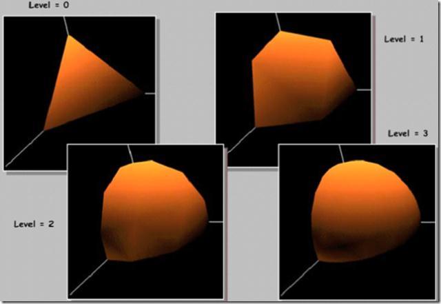
108 Tesselation Patches Tessellation stages operate on patches, a primitive type denoted by the constant GL_PATCHES. A patch primitive is a general-purpose primitive, where every n vertices is a new patch primitive. The number of vertices per patch can be defined on the application-level using: void glpatchparameteri(glenum pname, GLint value); with GL_PATCH_VERTICES as target and a value which has is on the halfopen range [1, GL_MAX_PATCH_VERTICES). The maximum number of patch vertices is implementation-dependent, but will never be less than 32. Patch primitives are always a sequence of individual patches; there is no such thing as a "patch strip" or "patch loop" or such. So for a given vertex stream, every group of value number of vertices will be a separate patch. If you need to do something like triangle strips, you should use Indexed Rendering to get similar behavior, though it will not reduce the number of vertices in the index list. Fortunately, the Post-Transform Cache should deal with any performance impact having more indices
109 Tesselation Tessellation Control Shader The first step of tessellation is the optional invocation of a tessellation control shader (TCS). The TCS has two jobs: Determine the amount of tessellation that a primitive should have. Perform any special transformations on the input patch data. The TCS can change the size of a patch, adding more vertices perpatch or providing fewer. However, a TCS cannot discard a patch (directly; it can do so indirectly), nor can it write multiple patches. Therefore, for each patch provided by the application, one patch will be provided to the next tessellation stage
110 Tesselation Tessellation Control Shader (continued) The TCS is optional. If no TCS is active in the current program or program pipeline, then the patch data is passed directly from the Vertex Shader invocations to the tessellation primitive generation step. The amount of tessellation done in this case is taken from default values set into the context. These are defined by the following function: void glpatchparameterfv(glenum pname, const GLfloat *values); When pname is GL_PATCH_DEFAULT_OUTER_LEVEL, values is a 4-element array of floats defining the four outer tessellation levels. When pname is GL_PATCH_DEFAULT_INNER_LEVEL, values is a 2-element array of floats defining the two inner tessellation levels. These default values correspond to the TCS per-patch output variables gl_tesslevelouter[4] and gl_tesslevelinner[2]
111 Tesselation Tessellation levels The amount of tessellation that is done over the abstract patch type is defined by inner and outer tessellation levels. These, as previously stated, are provided either by the TCS or by context parameters specified via glpatchparameter. They are a 4-vector of floats defining the "outer tessellation levels" and a 2-vector of floats defining the "inner tessellation levels." The specific interpretation depends on the abstract patch type being used, but the general idea is this. In most cases, each tessellation level defines how many segments an edge is tessellated into; so a tessellation level of 4 means that an edge will become 4 edges (2 vertices become 5). The "outer" tessellation levels define the tessellation for the outer edges of the primitive. This makes it possible for two or more patches to properly connect, while still having different tessellation levels within the patch. The inner tessellation levels are for the number of tessellations within the abstract patch
112 Tesselation Tessellation levels (continued) The spacing affects the effective tessellation level as follows: equal_spacing : Each tessellation level is individually clamped to the closed range [1, max ]. Then it is rounded up to the nearest integer to give the effective tessellation level. fractional_even_spacing : Each tessellation level is individually clamped to the closed range [2, max ]. Then it is rounded up to the nearest even integer to give the effective tessellation level. fractional_odd_spacing : Each tessellation level is individually clamped to the closed range [1, max - 1]. Then it is rounded up to the nearest odd integer to give the effective tessellation level. odd spacing even spacing

113 Tesselation Tessellating primitives Triangles: The abstract patch for triangle tessellation is a triangle, naturally. Only the first three outer tessellation levels are used, and only the first inner tessellation level is used. The outer tessellation levels apply to the edges shown in the diagram. Exactly how the inner tessellation level works is less intuitive than it seems. Each vertex generated and sent to the TES will be given Barycentric coordinates as the gl_tesscoord input. This coordinate defines where this vertex is located within the abstract triangle patch. The barycentric coordinates for the 3 vertices of the abstract triangle patch are shown in the diagram. All other vertices will be specified relative to these
114 Tesselation Tessellating primitives (continued) The algorithm for tessellation of triangles is based on tessellating the edges of the triangle, then building vertices and triangles from them. This makes the behavior of the inner tessellation level a bit unintuitive, since it does not directly correspond to the number of inner triangles. 1. Removes the most degenerate case. If all of the effective outer levels (as computed above) levels are exactly 1.0, and the effective inner level is also 1.0, then nothing is tessellated, and the TES will get 3 vertices and one triangle. And thus, none of the later steps take place. 2. If the effective inner level is 1.0 (and therefore at least one of the outer levels is > 1.0, otherwise we'd have hit the above condition), then the effective inner level is recomputed as though the user had specified e for the inner level, where e is a number infinitely close to zero. So e is a value just slightly above
115 Tesselation Tessellating primitives (continued) 3. Subdivide the edges of the abstract triangle patch based on the effective inner level. Yes, the algorithm begins by ignoring the outer tessellation levels; it applies the inner tessellation to all three outer edges 4. Build a series of concentric "rings" of inner triangles. At each corner of the outer triangle, the two neighboring subdivided vertices are taken. A vertex is computed from these two by finding the intersection of two perpendicular lines from these vertices. Perpendicular lines from the remaining vertices to the inner triangle's edges define where each edge of the new triangle is subdivided. This process is repeated, using the new ring triangle to generate the next inner ring, until one of two end conditions is met. If the triangle ring has no subdivided edges (only 3 vertices), then the process stops. If the triangle ring has exactly 2 subdivided edges (only 6 total vertices), then the "ring" it generates is not a triangle at all. It is a single vertex:


116 Tesselation Tessellating primitives (continued) By this algorithm, the number of inner triangle rings is half the effective inner tessellation level, rounded down. Note that if the inner level is even, the innermost ring will be a single vertex
117 Tesselation Tessellating primitives (continued) After producing these inner rings, the tessellation for the main outer triangle is discarded entirely. It is then re-tessellated in accord with the three effective outer tessellation levels
118 Tesselation Tessellating primitives (continued) With all the vertices generated, triangles must now be generated. The specification outlines a particular algorithm for doing so, but it leaves many of the details to the implementation. The specification guarantees: 1. Area of the triangle, in (u,v,w) space, will be completely covered by the generated triangulation. 2. No part of the area of the triangle will be covered more than once by the generated triangulation. 3. There will be edges between the neighboring vertices of each "ring" of triangles. That is, the dark lines in the above diagram are guaranteed by the specification to be there

119 Tesselation Tessellating primitives (continued) 4. If a vertex has corresponding vertices on the ring that immediately preceded it, then there will be an edge between that vertex and its corresponding ones (corners of ring triangles have 2 corresponding vertices). Similarly, if a vertex has a corresponding vertex on the ring within it, there will be an edge between them
120 Tesselation Control Shader The Tesselation Control Shader (TCS) controls how much tessellation a particular patch gets; it also defines the size of a patch, thus allowing it to augment data. It can also filter vertex data taken from the vertex shader. The main purpose of the TCS is to feed the tessellation levels to the Tessellation primitive generator stage, as well as to feed patch data (as its output values) to the Tessellation Evaluation Shader stage
121 Tesselation Control Shader For each patch provided during rendering, n TCS shader invocations will be processed, where n is the number of vertices in the output patch. So if a drawing command draws 20 patches, and each output patch has 4 vertices, there will be a total of 80 separate TCS invocations. The different invocations that provide data to the same patch are interconnected. These invocations all share their output values. They can read output values that other invocations for the same patch have written to. But in order to do so, they must use a synchronization mechanism to ensure that all other invocations for the patch have executed at least that far. Because of this, it is possible for TCS invocations to share data and communicate with one another
122 Tesselation Control Shader Output patch size The output patch size is the number of vertices in the output patch. It also determines the number of TCS invocations used to compute this patch data. The output patch size does not have to match the input patch size. The number of vertices in the output patch is defined with an output layout qualifier: layout(vertices = patch_size) out; patch_size must be an integral constant expression greater than zero and less than the patch limit
123 Tesselation Control Shader Inputs All inputs from vertex shaders to the TCS are aggregated into arrays, based on the size of the input patch. The size of these arrays is the number of input patches provided by the patch primitive. Every TCS invocation for an input patch has access to the same input data, save for gl_invocationid (see next slide) which will be different for each invocation. So any TCS invocation can look at the input vertex data for the entire input patch
124 Tesselation Control Shader User-defined inputs can be declared as unbounded arrays: in vec2 texcoord[]; You should not attempt to index this array past the number of input patch vertices. TCS inputs may have interpolation qualifiers on them. They have no actual function however. Tessellation Control Shaders provide the following built-in input variables: in int gl_patchverticesin; // the number of vertices in the input patch in int gl_primitiveid; // the index of the current patch within this rendering command in int gl_invocationid; // the index of the TCS invocation within this patch; a TCS invocation writes to per-vertex output variables by using this to index them
125 Tesselation Control Shader The TCS also takes the built-in variables output by the vertex shader: in gl_pervertex { vec4 gl_position; float gl_pointsize; float gl_clipdistance[]; } gl_in[gl_maxpatchvertices];
126 Tesselation Control Shader Outputs TCS output variables are passed directly to the Tessellation Evaluation Shader, without any form of interpolation (that's the TES's main job). These can be per-vertex outputs and per-patch outputs. Per-vertex outputs are aggregated into arrays. Therefore, a user-defined pervertex output variable would be defined as such: out vec2 vertextexcoord[]; The length of the array vertextexcoord.length() will always be the size of the output patch. So you don't need to restate it in the definition. A TCS can only ever write to the per-vertex output variable that corresponds to their invocation. So writes to per-vertex outputs must be of the form vertextexcoord[gl_invocationid]. Any expression that writes to a per-vertex output that doesn't index it with exactly gl_invocationid results in a compile-time error. Silly things like vertextexcoord[gl_invocationid ] will also error
127 Tesselation Control Shader Patch variables Per-patch output variables are not aggregated into arrays (unless you want them to be, in which case you must specify a size). All TCS invocations for this patch see the same patch variables. They are declared with the patch keyword: patch out vec4 data; Any TCS invocation can write to a per-patch output; indeed, all TCS invocations will generally write to a perpatch output. As long as they all write the same value, everything is fine
128 Tesselation Control Shader Built-in outputs Tessellation Control Shaders have the following built-in patch output variables: patch out float gl_tesslevelouter[4]; patch out float gl_tesslevelinner[2]; These define the outer and inner tessellation levels used by the tessellation primitive generator. They define how much tessellation to apply to the patch. Their exact meaning depends on the type of patch (and other settings) defined in the Tessellation Evaluation Shader. As with any other patch variable, multiple TCS invocations for the same patch can write to the same tessellation level variable, so long as they are all computing and writing the exact same value
129 Tesselation Control Shader TCS's also provide the following optional per-vertex output variables: out gl_pervertex { vec4 gl_position; float gl_pointsize; float gl_clipdistance[]; } gl_out[];
130 Tesselation Control Shader Synchronization TCS invocations that operate on the same patch can read each others output variables, whether per-patch or per-vertex. To do so, they must first ensure that those invocations have actually written to those variables. The value of all output variables is undefined initially. Ensuring that invocations have written to a variable requires synchronization between invocations. This is done via the barrier() function. When executed, it will not complete until all other TCS invocations for this patch have reached that barrier. This means that all writes have occurred by this point. However, subsequent writes to those variables may have occurred, so if you want to read those variables, make sure that another barrier() is issued before writing more to them. If there are no subsequent writes to those variables, then this should be fine
131 Tesselation Control Shader Synchronization (continued) The barrier() function has significant restrictions on where it can be placed. It must be placed: Directly in the main() function. It cannot be in any other functions or subroutines. Outside of any flow control. This includes if, for, switch, and the like. Before any use of return, even a conditional one. This ensures that every TCS invocation hits the same sequence of barrier() calls in the same order every time. The compiler will error if any of these restrictions are violated. Note: This is different from the restrictions on barrier() in Compute Shaders. Also, writes to TCS output variables do not use the rules for Incoherent Memory Access, so they do not need those memory barrier calls
132 Tesselation Control Shader Limitations There is a maximum output patch size, defined by GL_MAX_PATCH_VERTICES; the vertices output qualifier must be less than this value. The minimum required limit is 32. There are other limitations on output size, however. The number of components for active per-vertex output variables may not exceed GL_MAX_TESS_CONTROL_OUTPUT_COMPONENTS. The minimum required limit is 128. The number of components for active per-patch output variables may not exceed GL_MAX_TESS_PATCH_COMPONENTS. The minimum required limit is 120. Note that the gl_tesslevelouter and gl_tesslevelinner outputs do not count against this limit (but other built-in outputs do if you use them. There is a limit on the total number of components that can go into an output patch. To compute the total number of components, multiply the number of active per-vertex components by the number of output vertices, then add the number of active per-patch components. This number may not exceed GL_MAX_TESS_CONTROL_TOTAL_OUTPUT_COMPONENTS. The minimum required limit is 4096, which is not quite enough to use a 32-vertex patch with 128 pervertex components and 120 per-patch components. But it's still a lot
133 Tesselation Evaluation Shader The Tesselation Evaluation Shader (TES) takes the abstract patch generated by the tessellation primitive generation stage, as well as the actual vertex data for the entire patch, and generates a particular vertex from it. Each TES invocation generates a single vertex. It can also take per-patch data provided by the Tessellation Control Shader. The number of times the TES is invoked can differ from implementation to implementation. It will be invoked at least once per tessellated vertex in the abstract patch, but there is no guarantee that the TES won't be invoked multiple times for the same vertex. However, like the Vertex Shader, the TES is expected to output the same value for the same vertex in the abstract patch
134 Tesselation Evaluation Shader Tessellation options The presence of an active TES in a program or program pipeline is what governs whether or not the tessellation primitive generation stage will occur. Because of that, many options that control the particular form of tessellation are specified in the TES itself. The details of what these mean for the tessellation results are described in the section on the tessellation primitive generation. This section will only describe how to specify these options, not go into detail on exactly what they do. All of these options are input layout qualifiers. They are specified using that syntax: layout(param1, param2,...) in; They can be specified as separate statements or all in one. However, each particular type of parameter can only be specified once (you technically can specify them multiple times, but they all must be the same)
135 Tesselation Evaluation Shader Abstract patch type The TES defines the type of abstract patch that will be tessellated. The possible values for this are: isolines : The patch is a rectangular block of parallel lines. The output is a series of lines. triangles : The patch is a triangle. The output is a series of triangles. quads : The patch is a quadrilateral. The output is a series of triangles. The TES must provide this option
136 Tesselation Evaluation Shader Spacing The TES has options that control the spacing between tessellated vertices of the abstract patch. The possible values for this are: equal_spacing : There will be equal distances between vertices in the abstract patch. fractional_even_spacing : There will always be an even number of segments. Two of the segments will grow and shrink based on how close the tessellation level is to generating more vertices. fractional_odd_spacing : As even-spacing, but there will always be an odd number of segments. This is optional. If the TES does not specify this parameter, equal_spacing will be used
137 Tesselation Evaluation Shader Primitive ordering When emitting triangles, the Winding Order can be important for face culling. The process of tessellation takes place over an abstract patch, which is not in any particular coordinate system. It is the TES's responsibility to take abstract patch coordinates and generate real clip-space (or whatever your Geometry Shader expects) positions from them. Therefore, maintaining the proper winding order for triangles is the job of the TES. To facilitate that, the TES has the ability to control the winding order of the primitive generator. This is done via the cw and ccw parameters. Remember that this parameter only controls the winding order of the triangles within the abstract patch. The winding order of the final triangle primitives will ultimately be based on the TES's generated positions. As such, different triangles generated from the same patch can have different final winding orders. This parameter is optional. If the TES does not specify this parameter, ccw will be used. Since lines don't have a winding order, this parameter is useless when using the isolines patch type or point_mode rendering
138 Tesselation Evaluation Shader Primitive generation Normally, the kind of Primitive emitted by the primitive generator is defined by the abstract patch type. isolines will generate a series of line-strips, while the others will generate a series of triangles. The TES can force the primitive generator to override this and simply generate a point primitive for each vertex in the tessellated patch. A Geometry Shader could modify these and build a quad from each point, or they could simply be drawn as points. To do this, use the layout qualifier point_mode. Obviously specifying this makes the ordering parameter unimportant
139 Tesselation Evaluation Shader Inputs The inputs for the TES are the per-vertex and per-patch outputs from the Tessellation Control Shader (or directly from the vertex shader if no TCS is active). Each TES invocation can access all of the outputs for a particular patch. Per-vertex inputs from the TCS are arrays of values, indexed by a vertex index. Like TCS outputs, TES inputs can be declared without an explicit size: in vec2 vertextexcoord[]; The length of the array vertextexcoord.length() is the size of the input patch. Per-patch outputs from the TCS can be taken as inputs in the TES using the patch keyword: patch in vec4 data;
140 Tesselation Evaluation Shader Inputs (continued) Tessellation Evaluation Shaders have the following built-in inputs: in vec3 gl_tesscoord; he location within the tessellated abstract patch for this particular vertex. Every input parameter other than this one will be identical for all TES invocations within a patch. Which components of this vec3 that have valid values depends on the abstract patch type. For isolines and quads, only the XY components have valid values. For triangles, all three components have valid values. All valid values are normalized floats (on the range [0, 1])
141 Tesselation Evaluation Shader Inputs (continued) in int gl_patchverticesin; the vertex count for the patch being processed. This is either the output vertex count specified by the TCS, or the patch vertex size specified by glpatchparameter if no TCS is active. Attempts to index per-vertex inputs by a value greater than or equal to gl_patchverticesin results in undefined behavior. in int gl_primitiveid; he index of the current patch in the series of patches being processed for this draw call. Primitive Restart, if used, has no effect on the primitive ID. Note: The tessellation primitive generator will cull patches that have a zero for one of the active outer tessellation levels. The intent of the specification seems to be that gl_primitiveid will still be incremented for culled patches. So the primitive ID for the TES is equivalent to the ID for the TCS invocations that generated that patch. But this is not entirely clear from the spec itself
142 Tesselation Evaluation Shader Inputs (continued) The TES also has access to the tessellation levels provided for the patch by the TCS or by OpenGL: patch in float gl_tesslevelouter[4]; patch in float gl_tesslevelinner[2]; Only the outer and inner levels actually used by the abstract patch are valid. For example, if this TES uses isolines, only gl_tesslevelouter[0] and gl_tesslevelouter[1] will have valid values
143 Tesselation Evaluation Shader Inputs (continued) The TES also takes the built-in per-vertex variables output by the TCS: in gl_pervertex { vec4 gl_position; float gl_pointsize; float gl_clipdistance[]; } gl_in[gl_maxpatchvertices]; Note that just because gl_in is defined to have gl_maxpatchvertices entries does not mean that you can access beyond gl_patchverticesin and get reasonable values
144 Tesselation Evaluation Shader Outputs Each TES invocation outputs a separate vertex worth of data. Therefore, the TES outputs are scalars (you can have output arrays, but, they won't be treated specially the way per-vertex input arrays are). User-defined outputs from the TES can have interpolation qualifiers on them. Tessellation Evaluation Shaders have the following built-in outputs. out gl_pervertex { }; vec4 gl_position; float gl_pointsize; float gl_clipdistance[];
145 Tesselation Evaluation Shader Outputs (continued) gl_pervertex defines an interface block for outputs. The block is defined without an instance name, so that prefixing the names is not required. These variables only take on the meanings below if this shader is the last active Vertex Processing stage, and if rasterization is still active (ie: GL_RASTERIZER_DISCARD is not enabled). The text below explains how the Vertex Post-Processing system uses the variables. These variables may not be redeclared with interpolation qualifiers. gl_position : the clip-space output position of the current vertex. gl_pointsize: the pixel width/height of the point being rasterized. It only has a meaning when rendering point primitives, which in a TES requires using the point_mode input layout qualifier. gl_clipdistance: allows the shader to set the distance from the vertex to each User-Defined Clip Plane. A positive distance means that the vertex is inside/behind the clip plane, and a negative distance means it is outside/in front of the clip plane. Each element in the array is one clip plane. In order to use this variable, the user must manually redeclare it with an explicit size
146 Tesselation Shaders: Example Tesselation Control Shader #version 410 core layout(vertices = 4) out; void main(void) { } gl_tesslevelouter[0] = 2.0; gl_tesslevelouter[1] = 4.0; gl_tesslevelouter[2] = 6.0; gl_tesslevelouter[3] = 8.0; gl_tesslevelinner[0] = 8.0; gl_tesslevelinner[1] = 8.0; gl_out[gl_invocationid].gl_position = gl_in[gl_invocationid].gl_position;
147 Tesselation Shaders: Example Tesselation Evaluation Shader #version 410 core layout(quads, equal_spacing, ccw) in; //quad interpol vec4 interpolate(in vec4 v0, in vec4 v1, in vec4 v2, in vec4 v3) { } vec4 a = mix(v0, v1, gl_tesscoord.x); vec4 b = mix(v3, v2, gl_tesscoord.x); return mix(a, b, gl_tesscoord.y);
148 Tesselation Shaders: Example Tesselation Evaluation Shader (continued) void main() { } gl_position = interpolate( gl_in[0].gl_position, gl_in[1].gl_position, gl_in[2].gl_position, gl_in[3].gl_position);

149 Tesselation Shaders: Example
GLSL II. Objectives. Coupling GLSL to Applications Example applications
 GLSL II Ed Angel Professor of Computer Science, Electrical and Computer Engineering, and Media Arts Director, Arts Technology Center University of New Mexico Objectives Coupling GLSL to Applications Example
Objectives. Coupling GLSL to Applications Example applications
 GLSL II Ed Angel Professor of Computer Science, Electrical and Computer Engineering, and Media Arts Director, Arts Technology Center University of New Mexico Objectives Coupling GLSL to Applications Example
Supplement to Lecture 22
 Supplement to Lecture 22 Programmable GPUs Programmable Pipelines Introduce programmable pipelines - Vertex shaders - Fragment shaders Introduce shading languages - Needed to describe shaders - RenderMan
CMPS160 Shader-based OpenGL Programming. All slides originally from Prabath Gunawardane, et al. unless noted otherwise
 CMPS160 Shader-based OpenGL Programming All slides originally from Prabath Gunawardane, et al. unless noted otherwise Shader gallery I Above: Demo of Microsoft s XNA game platform Right: Product demos
Objectives. Open GL Shading Language (GLSL)
") Open GL Shading Language (GLSL) Objectives Shader applications Vertex shaders Fragment shaders Programming shaders Cg GLSL Coupling GLSL to Applications Example applications 1 Vertex Shader Applications
Open GL Shading Language (GLSL) Objectives Shader applications Vertex shaders Fragment shaders Programming shaders Cg GLSL Coupling GLSL to Applications Example applications 1 Vertex Shader Applications
CMPS160 Shader-based OpenGL Programming
 CMPS160 Shader-based OpenGL Programming Shader gallery I Above: Demo of Microsoft s XNA game platform Right: Product demos by nvidia (top) and Radeon (bottom) Shader gallery II Above: Kevin Boulanger (PhD
12.2 Programmable Graphics Hardware
 Fall 2018 CSCI 420: Computer Graphics 12.2 Programmable Graphics Hardware Kyle Morgenroth http://cs420.hao-li.com 1 Introduction Recent major advance in real time graphics is the programmable pipeline:
Programmable Graphics Hardware
 CSCI 480 Computer Graphics Lecture 14 Programmable Graphics Hardware [Ch. 9] March 2, 2011 Jernej Barbic University of Southern California OpenGL Extensions Shading Languages Vertex Program Fragment Program
Advanced Graphics. The Shader knows. Alex Benton, University of Cambridge Supported in part by Google UK, Ltd
 Advanced Graphics The Shader knows Alex Benton, University of Cambridge A.Benton@damtp.cam.ac.uk Supported in part by Google UK, Ltd What is the shader? Local space World space Viewing space Local space
The Graphics Pipeline and OpenGL III: OpenGL Shading Language (GLSL 1.10)!
!") ! The Graphics Pipeline and OpenGL III: OpenGL Shading Language (GLSL 1.10)! Gordon Wetzstein! Stanford University! EE 267 Virtual Reality! Lecture 4! stanford.edu/class/ee267/! Updates! for 24h lab access:
! The Graphics Pipeline and OpenGL III: OpenGL Shading Language (GLSL 1.10)! Gordon Wetzstein! Stanford University! EE 267 Virtual Reality! Lecture 4! stanford.edu/class/ee267/! Updates! for 24h lab access:
Vertex & Fragment shaders
 Vertex & Fragment shaders The next big step in graphics hardware Adds programmability to the previously fixed rendering pipeline The OpenGL Shading Language (a.k.a. GLSL, glslang) Vertex shaders: programs
Tuesday, 23 March OpenGL Shading Language
 OpenGL Shading Language GLSL Is a high level shading language based on the C programming language. It was created by the OpenGL ARB to give developers more direct control of the graphics pipeline without
GLSL. OpenGL Shading Language. OpenGL 1.5 Logical Diagram. OpenGL 2.0 Logical Diagram
 OpenGL Shading Language GLSL Is a high level shading language based on the C programming language. It was created by the OpenGL ARB to give developers more direct control of the graphics pipeline without
Programming with OpenGL Part 3: Shaders. Ed Angel Professor of Emeritus of Computer Science University of New Mexico
 Programming with OpenGL Part 3: Shaders Ed Angel Professor of Emeritus of Computer Science University of New Mexico 1 Objectives Simple Shaders - Vertex shader - Fragment shaders Programming shaders with
Programming shaders & GPUs Christian Miller CS Fall 2011
 Programming shaders & GPUs Christian Miller CS 354 - Fall 2011 Fixed-function vs. programmable Up until 2001, graphics cards implemented the whole pipeline for you Fixed functionality but configurable
GLSL 1: Basics. J.Tumblin-Modified SLIDES from:
 GLSL 1: Basics J.Tumblin-Modified SLIDES from: Ed Angel Professor of Computer Science, Electrical and Computer Engineering, and Media Arts Director, Arts Technology Center University of New Mexico and
Programmable shader. Hanyang University
 Programmable shader Hanyang University Objective API references (will be skipped) Examples Simple shader Phong shading shader INTRODUCTION GLSL(OPENGL SHADING LANGUAGE) Scalar Data types Structure Structures
Lecture 09: Shaders (Part 1)
") Lecture 09: Shaders (Part 1) CSE 40166 Computer Graphics Peter Bui University of Notre Dame, IN, USA November 9, 2010 OpenGL Rendering Pipeline OpenGL Rendering Pipeline (Pseudo-Code) 1 f o r gl_vertex
Lecture 09: Shaders (Part 1) CSE 40166 Computer Graphics Peter Bui University of Notre Dame, IN, USA November 9, 2010 OpenGL Rendering Pipeline OpenGL Rendering Pipeline (Pseudo-Code) 1 f o r gl_vertex
Information Coding / Computer Graphics, ISY, LiTH GLSL. OpenGL Shading Language. Language with syntax similar to C
 GLSL OpenGL Shading Language Language with syntax similar to C Syntax somewhere between C och C++ No classes. Straight ans simple code. Remarkably understandable and obvious! Avoids most of the bad things
GLSL Introduction. Fu-Chung Huang. Thanks for materials from many other people
 GLSL Introduction Fu-Chung Huang Thanks for materials from many other people Shader Languages Currently 3 major shader languages Cg (Nvidia) HLSL (Microsoft) Derived from Cg GLSL (OpenGL) Main influences
The Transition from RenderMan to the OpenGL Shading Language (GLSL)
") 1 The Transition from RenderMan to the OpenGL Shading Language (GLSL) Mike Bailey mjb@cs.oregonstate.edu This work is licensed under a Creative Commons Attribution-NonCommercial- NoDerivatives 4.0 International
1 The Transition from RenderMan to the OpenGL Shading Language (GLSL) Mike Bailey mjb@cs.oregonstate.edu This work is licensed under a Creative Commons Attribution-NonCommercial- NoDerivatives 4.0 International
The Graphics Pipeline and OpenGL III: OpenGL Shading Language (GLSL 1.10)!
!") ! The Graphics Pipeline and OpenGL III: OpenGL Shading Language (GLSL 1.10)! Gordon Wetzstein! Stanford University! EE 267 Virtual Reality! Lecture 4! stanford.edu/class/ee267/! Lecture Overview! Review
! The Graphics Pipeline and OpenGL III: OpenGL Shading Language (GLSL 1.10)! Gordon Wetzstein! Stanford University! EE 267 Virtual Reality! Lecture 4! stanford.edu/class/ee267/! Lecture Overview! Review
Comp 410/510 Computer Graphics Spring Programming with OpenGL Part 3: Shaders
 Comp 410/510 Computer Graphics Spring 2018 Programming with OpenGL Part 3: Shaders Objectives Basic shaders - Vertex shader - Fragment shader Programming shaders with GLSL Finish first program void init(void)
Some advantages come from the limited environment! No classes. Stranight ans simple code. Remarkably. Avoids most of the bad things with C/C++.
 GLSL OpenGL Shading Language Language with syntax similar to C Syntax somewhere between C och C++ No classes. Stranight ans simple code. Remarkably understandable and obvious! Avoids most of the bad things
Programming with OpenGL Shaders I. Adapted From: Ed Angel Professor of Emeritus of Computer Science University of New Mexico
 Programming with OpenGL Shaders I Adapted From: Ed Angel Professor of Emeritus of Computer Science University of New Mexico 0 Objectives Shader Basics Simple Shaders Vertex shader Fragment shaders 1 Vertex
CSE 167: Introduction to Computer Graphics Lecture #13: GLSL. Jürgen P. Schulze, Ph.D. University of California, San Diego Fall Quarter 2015
 CSE 167: Introduction to Computer Graphics Lecture #13: GLSL Jürgen P. Schulze, Ph.D. University of California, San Diego Fall Quarter 2015 Announcements Project 6 due Friday Next Thursday: Midterm #2
Introduction to the OpenGL Shading Language (GLSL)
") 1 Introduction to the OpenGL Shading Language (GLSL) This work is licensed under a Creative Commons Attribution-NonCommercial- NoDerivatives 4.0 International License Mike Bailey mjb@cs.oregonstate.edu
1 Introduction to the OpenGL Shading Language (GLSL) This work is licensed under a Creative Commons Attribution-NonCommercial- NoDerivatives 4.0 International License Mike Bailey mjb@cs.oregonstate.edu
Programming with OpenGL Shaders I. Adapted From: Ed Angel Professor of Emeritus of Computer Science University of New Mexico
 Programming with OpenGL Shaders I Adapted From: Ed Angel Professor of Emeritus of Computer Science University of New Mexico Objectives Shader Programming Basics Simple Shaders Vertex shader Fragment shaders
The Basic Computer Graphics Pipeline, OpenGL-style. Introduction to the OpenGL Shading Language (GLSL)
") Introduction to the OpenGL Shading Language (GLSL) 1 The Basic Pipeline, OpenGL-style Vertex, Normal, Color ModelViewMatrix, ProjectionMatrix, ModelViewProjectionMatrix 2 MC Model WC View Per-vertex Projection
Introduction to the OpenGL Shading Language (GLSL) 1 The Basic Pipeline, OpenGL-style Vertex, Normal, Color ModelViewMatrix, ProjectionMatrix, ModelViewProjectionMatrix 2 MC Model WC View Per-vertex Projection
Shaders. Slide credit to Prof. Zwicker
 Shaders Slide credit to Prof. Zwicker 2 Today Shader programming 3 Complete model Blinn model with several light sources i diffuse specular ambient How is this implemented on the graphics processor (GPU)?
Further Graphics. Advanced Shader Techniques. Alex Benton, University of Cambridge Supported in part by Google UK, Ltd
 Further Graphics Advanced Shader Techniques 1 Alex Benton, University of Cambridge alex@bentonian.com Supported in part by Google UK, Ltd Lighting and Shading (a quick refresher) Recall the classic lighting
Today. Rendering - III. Outline. Texturing: The 10,000m View. Texture Coordinates. Specifying Texture Coordinates in GL
 Today Rendering - III CS148, Summer 2010 Graphics Pipeline and Programmable Shaders Artist Workflow Siddhartha Chaudhuri 1 2 Outline Texturing: The 10,000m View Intro to textures The fixed-function graphics
Graphics Programming. Computer Graphics, VT 2016 Lecture 2, Chapter 2. Fredrik Nysjö Centre for Image analysis Uppsala University
 Graphics Programming Computer Graphics, VT 2016 Lecture 2, Chapter 2 Fredrik Nysjö Centre for Image analysis Uppsala University Graphics programming Typically deals with How to define a 3D scene with a
CSE 167: Lecture #8: GLSL. Jürgen P. Schulze, Ph.D. University of California, San Diego Fall Quarter 2012
 CSE 167: Introduction to Computer Graphics Lecture #8: GLSL Jürgen P. Schulze, Ph.D. University of California, San Diego Fall Quarter 2012 Announcements Homework project #4 due Friday, November 2 nd Introduction:
Programmable GPUs. Real Time Graphics 11/13/2013. Nalu 2004 (NVIDIA Corporation) GeForce 6. Virtua Fighter 1995 (SEGA Corporation) NV1
 GeForce 6. Virtua Fighter 1995 (SEGA Corporation) NV1") Programmable GPUs Real Time Graphics Virtua Fighter 1995 (SEGA Corporation) NV1 Dead or Alive 3 2001 (Tecmo Corporation) Xbox (NV2A) Nalu 2004 (NVIDIA Corporation) GeForce 6 Human Head 2006 (NVIDIA Corporation)
Programmable GPUs Real Time Graphics Virtua Fighter 1995 (SEGA Corporation) NV1 Dead or Alive 3 2001 (Tecmo Corporation) Xbox (NV2A) Nalu 2004 (NVIDIA Corporation) GeForce 6 Human Head 2006 (NVIDIA Corporation)
Programmable Graphics Hardware
 Programmable Graphics Hardware Outline 2/ 49 A brief Introduction into Programmable Graphics Hardware Hardware Graphics Pipeline Shading Languages Tools GPGPU Resources Hardware Graphics Pipeline 3/ 49
The OpenGL Shading Language
 The OpenGL Shading Language GLSL In the previous lecture we looked at the process of loading shaders into the programmable hardware (GPU) The actual language syntax of GLSL and the principles behind it
Introduction to the OpenGL Shading Language
 Introduction to the OpenGL Shading Language Randi Rost Director of Developer Relations, 3Dlabs 08-Dec-2005 1 Why use graphics programmability? Graphics hardware has changed radically Fixed functionality
GLSL v1.20. Scott MacHaffie Schrödinger, Inc.
 1 GLSL v1.20 Scott MacHaffie Schrödinger, Inc. http://www.schrodinger.com Table of Contents Introduction...2 Example 01: Trivial shader...2 Syntax...3 Types of variables...3 Example 02: Materials vertex
Today s Agenda. Shaders fundamentals. Programming with shader-based OpenGL
 Today s Agenda Shaders fundamentals Programming with shader-based OpenGL Shaders Like a function call data are passed in, processed, and passed back out -- Shreiner et al, OpenGL Programming Guide GLSL
Shader Programs. Lecture 30 Subsections 2.8.2, Robb T. Koether. Hampden-Sydney College. Wed, Nov 16, 2011
 Shader Programs Lecture 30 Subsections 2.8.2, 2.8.3 Robb T. Koether Hampden-Sydney College Wed, Nov 16, 2011 Robb T. Koether (Hampden-Sydney College) Shader Programs Wed, Nov 16, 2011 1 / 43 Outline 1
GLSL Geometry Shaders
 GLSL Geometry Shaders 1 This work is licensed under a Creative Commons Attribution-NonCommercial-NoDerivatives 4.0 International License Mike Bailey mjb@cs.oregonstate.edu geometry_shaders.pptx Here s
HW-Tessellation Basics
 HW-Tessellation Basics Peter Houska Institute of Computer Graphics and Algorithms Vienna University of Technology Tessellation Video [UnHe] Institute of Computer Graphics and Algorithms 1 What is Tessellation?
Shaders. Introduction. OpenGL Grows via Extensions. OpenGL Extensions. OpenGL 2.0 Added Shaders. Shaders Enable Many New Effects
 CSCI 420 Computer Graphics Lecture 4 Shaders Jernej Barbic University of Southern California Shading Languages GLSL Vertex Array Objects Vertex Shader Fragment Shader [Angel Ch. 1, 2, A] Introduction The
Sign up for crits! Announcments
 Sign up for crits! Announcments Reading for Next Week FvD 16.1-16.3 local lighting models GL 5 lighting GL 9 (skim) texture mapping Modern Game Techniques CS248 Lecture Nov 13 Andrew Adams Overview The
Technical Game Development II. Reference: Rost, OpenGL Shading Language, 2nd Ed., AW, 2006 The Orange Book Also take CS 4731 Computer Graphics
 Shader Programming Technical Game Development II Professor Charles Rich Computer Science Department rich@wpi.edu Reference: Rost, OpenGL Shading Language, 2nd Ed., AW, 2006 The Orange Book Also take CS
3D Game Programming Programmable Pipelines. Ming-Te Chi Department of Computer Science, National Chengchi University
 3D Game Programming Programmable Pipelines Ming-Te Chi Department of Computer Science, National Chengchi University Outline Programmable Pipelines(4ed CH15) (5th CH5) Vertex shaders Fragment shaders Introduce
Real-Time Rendering (Echtzeitgraphik) Michael Wimmer
 Michael Wimmer") Real-Time Rendering (Echtzeitgraphik) Michael Wimmer wimmer@cg.tuwien.ac.at Walking down the graphics pipeline Application Geometry Rasterizer What for? Understanding the rendering pipeline is the key
Real-Time Rendering (Echtzeitgraphik) Michael Wimmer wimmer@cg.tuwien.ac.at Walking down the graphics pipeline Application Geometry Rasterizer What for? Understanding the rendering pipeline is the key
GLSL Introduction. Fu-Chung Huang. Thanks for materials from many other people
 GLSL Introduction Fu-Chung Huang Thanks for materials from many other people Programmable Shaders //per vertex inputs from main attribute aposition; attribute anormal; //outputs to frag. program varying
Today s Agenda. Basic design of a graphics system. Introduction to OpenGL
 Today s Agenda Basic design of a graphics system Introduction to OpenGL Image Compositing Compositing one image over another is most common choice can think of each image drawn on a transparent plastic
Lecture 5 Vertex and Fragment Shaders-1. CITS3003 Graphics & Animation
 Lecture 5 Vertex and Fragment Shaders-1 CITS3003 Graphics & Animation E. Angel and D. Shreiner: Interactive Computer Graphics 6E Addison-Wesley 2012 Objectives The rendering pipeline and the shaders Data
CSE 4431/ M Advanced Topics in 3D Computer Graphics. TA: Margarita Vinnikov
 CSE 4431/5331.03M Advanced Topics in 3D Computer Graphics TA: Margarita Vinnikov mvinni@cse.yorku.ca The OpenGL 4.x pipeline 2 new Programmable stages Tessellation Control Shader(GL_TESS_CONTROL_SHADER)
Programmable Shading. University of Texas at Austin CS354 - Computer Graphics
 Programmable Shading University of Texas at Austin CS354 - Computer Graphics Spring 2009 Don Fussell Lighting, Texturing, Shading Discussed Transformation, Texturing, and Lighting What if We could write
Shader Programming. Daniel Wesslén, Stefan Seipel, Examples
 Shader Programming Daniel Wesslén, dwn@hig.se Stefan Seipel, ssl@hig.se Examples 1 Per-pixel lighting Texture convolution filtering 2 Post-processing, animated procedural textures Vertex displacement mapping
Technical Game Development II. Reference: Rost, OpenGL Shading Language, 2nd Ed., AW, 2006 The Orange Book Also take CS 4731 Computer Graphics
 Shader Programming Technical Game Development II Professor Charles Rich Computer Science Department rich@wpi.edu Reference: Rost, OpenGL Shading Language, 2nd Ed., AW, 2006 The Orange Book Also take CS
Advanced Graphics. OpenGL and Shaders II. Alex Benton, University of Cambridge Supported in part by Google UK, Ltd
 Advanced Graphics OpenGL and Shaders II 1 Alex Benton, University of Cambridge A.Benton@damtp.cam.ac.uk Supported in part by Google UK, Ltd 2.Perspective and Camera Control It s up to you to implement
SHADER PROGRAMMING. Based on Jian Huang s lecture on Shader Programming
 SHADER PROGRAMMING Based on Jian Huang s lecture on Shader Programming What OpenGL 15 years ago could do http://www.neilturner.me.uk/shots/opengl-big.jpg What OpenGL can do now What s Changed? 15 years
CSE 167: Introduction to Computer Graphics Lecture #7: GLSL. Jürgen P. Schulze, Ph.D. University of California, San Diego Spring Quarter 2016
 CSE 167: Introduction to Computer Graphics Lecture #7: GLSL Jürgen P. Schulze, Ph.D. University of California, San Diego Spring Quarter 2016 Announcements Project 2 due Friday 4/22 at 2pm Midterm #1 on
OpenGL pipeline Evolution and OpenGL Shading Language (GLSL) Part 2/3 Vertex and Fragment Shaders
 Part 2/3 Vertex and Fragment Shaders") OpenGL pipeline Evolution and OpenGL Shading Language (GLSL) Part 2/3 Vertex and Fragment Shaders Prateek Shrivastava CS12S008 shrvstv@cse.iitm.ac.in 1 GLSL Data types Scalar types: float, int, bool Vector
OpenGL pipeline Evolution and OpenGL Shading Language (GLSL) Part 2/3 Vertex and Fragment Shaders Prateek Shrivastava CS12S008 shrvstv@cse.iitm.ac.in 1 GLSL Data types Scalar types: float, int, bool Vector
Lab 9 - Metal and Glass
 Lab 9 - Metal and Glass Let the form of an object be what it may, light, shade, and perspective will always make it beautiful. -John Constable Prologue Support code: /course/cs1230/src/labs/lab09 This
An Introduction to 3D Computer Graphics, Stereoscopic Image, and Animation in OpenGL and C/C++ Fore June
 An Introduction to 3D Computer Graphics, Stereoscopic Image, and Animation in OpenGL and C/C++ Fore June Appendix D OpenGL Shading Language (GLSL) D.1 Extending OpenGL The OpenGL architecture we have presented
Introduction to Shaders for Visualization. The Basic Computer Graphics Pipeline
 Introduction to Shaders for Visualization Mike Bailey The Basic Computer Graphics Pipeline Model Transform View Transform Per-vertex Lighting Projection Transform Homogeneous Division Viewport Transform
Introduction to Computer Graphics. Hardware Acceleration Review
 Introduction to Computer Graphics Hardware Acceleration Review OpenGL Project Setup Create a command-line style project in Xcode 4 Select the project file and click Build Phases tab Add OpenGL.framework
Computergrafik. Matthias Zwicker. Herbst 2010
 Computergrafik Matthias Zwicker Universität Bern Herbst 2010 Today Bump mapping Shadows Shadow mapping Shadow mapping in OpenGL Bump mapping Surface detail is often the result of small perturbations in
How to use tessellation to add geometric detail to your scenes. How to use geometry shaders to process whole primitives and create geometry on the fly
 Chapter 8 Primitive Processing WHAT YOU LL LEARN IN THIS CHAPTER How to use tessellation to add geometric detail to your scenes How to use geometry shaders to process whole primitives and create geometry
EDAF80 Introduction to Computer Graphics. Seminar 3. Shaders. Michael Doggett. Slides by Carl Johan Gribel,
 EDAF80 Introduction to Computer Graphics Seminar 3 Shaders Michael Doggett 2017 Slides by Carl Johan Gribel, 2010-13 Today OpenGL Shader Language (GLSL) Shading theory Assignment 3: (you guessed it) writing
CS770/870 Fall 2015 Advanced GLSL
 Expanded Graphics Pipeline CS770/870 Fall 2015 Advanced GLSL Geometry definition Shaders can actually be inserted in more places in pipeline Vertex and fragment shaders are most important Vertex shader
CS4621/5621 Fall Computer Graphics Practicum Intro to OpenGL/GLSL
 CS4621/5621 Fall 2015 Computer Graphics Practicum Intro to OpenGL/GLSL Professor: Kavita Bala Instructor: Nicolas Savva with slides from Balazs Kovacs, Eston Schweickart, Daniel Schroeder, Jiang Huang
Introduction to Shaders.
 Introduction to Shaders Marco Benvegnù hiforce@gmx.it www.benve.org Summer 2005 Overview Rendering pipeline Shaders concepts Shading Languages Shading Tools Effects showcase Setup of a Shader in OpenGL
CS770/870 Spring 2017 Open GL Shader Language GLSL
 Preview CS770/870 Spring 2017 Open GL Shader Language GLSL Review traditional graphics pipeline CPU/GPU mixed pipeline issues Shaders GLSL graphics pipeline Based on material from Angel and Shreiner, Interactive
CS770/870 Spring 2017 Open GL Shader Language GLSL
 CS770/870 Spring 2017 Open GL Shader Language GLSL Based on material from Angel and Shreiner, Interactive Computer Graphics, 6 th Edition, Addison-Wesley, 2011 Bailey and Cunningham, Graphics Shaders 2
CS GPU and GPGPU Programming Lecture 7: Shading and Compute APIs 1. Markus Hadwiger, KAUST
 CS 380 - GPU and GPGPU Programming Lecture 7: Shading and Compute APIs 1 Markus Hadwiger, KAUST Reading Assignment #4 (until Feb. 23) Read (required): Programming Massively Parallel Processors book, Chapter
CS 432 Interactive Computer Graphics
 CS 432 Interactive Computer Graphics Lecture 2 Part 2 Introduction to Shaders Matt Burlick - Drexel University - CS 432 1 Shaders To understand shaders, let s look at the graphics pipeline again The job
Computergrafik. Matthias Zwicker Universität Bern Herbst 2016
 Computergrafik Matthias Zwicker Universität Bern Herbst 2016 Today More shading Environment maps Reflection mapping Irradiance environment maps Ambient occlusion Reflection and refraction Toon shading
2D graphics with WebGL
 2D graphics with WebGL Some material contained here is adapted from the book s slides. September 7, 2015 (Dr. Mihail) 2D graphics September 7, 2015 1 / 22 Graphics Pipeline (Dr. Mihail) 2D graphics September
OpenGL Programmable Shaders
 h gpup 1 Topics Rendering Pipeline Shader Types OpenGL Programmable Shaders sh gpup 1 OpenGL Shader Language Basics h gpup 1 EE 4702-X Lecture Transparency. Formatted 9:03, 20 October 2014 from shaders2.
X. GPU Programming. Jacobs University Visualization and Computer Graphics Lab : Advanced Graphics - Chapter X 1
 X. GPU Programming 320491: Advanced Graphics - Chapter X 1 X.1 GPU Architecture 320491: Advanced Graphics - Chapter X 2 GPU Graphics Processing Unit Parallelized SIMD Architecture 112 processing cores
Graphics Hardware. Instructor Stephen J. Guy
 Instructor Stephen J. Guy Overview What is a GPU Evolution of GPU GPU Design Modern Features Programmability! Programming Examples Overview What is a GPU Evolution of GPU GPU Design Modern Features Programmability!
Technical Game Development II. Reference: Rost, OpenGL Shading Language, 2nd Ed., AW, 2006 The Orange Book IMGD 4000 (D 10) 1
 1") Shader Programming Technical Game Development II Professor Charles Rich Computer Science Department rich@wpi.edu Reference: Rost, OpenGL Shading Language, 2nd Ed., AW, 2006 The Orange Book IMGD 4000 (D
Shader Programming Technical Game Development II Professor Charles Rich Computer Science Department rich@wpi.edu Reference: Rost, OpenGL Shading Language, 2nd Ed., AW, 2006 The Orange Book IMGD 4000 (D
CS230 : Computer Graphics Lecture 4. Tamar Shinar Computer Science & Engineering UC Riverside
 CS230 : Computer Graphics Lecture 4 Tamar Shinar Computer Science & Engineering UC Riverside Shadows Shadows for each pixel do compute viewing ray if ( ray hits an object with t in [0, inf] ) then compute
Pipeline Operations. CS 4620 Lecture Steve Marschner. Cornell CS4620 Spring 2018 Lecture 11
 Pipeline Operations CS 4620 Lecture 11 1 Pipeline you are here APPLICATION COMMAND STREAM 3D transformations; shading VERTEX PROCESSING TRANSFORMED GEOMETRY conversion of primitives to pixels RASTERIZATION
INF3320 Computer Graphics and Discrete Geometry
 INF3320 Computer Graphics and Discrete Geometry The OpenGL pipeline Christopher Dyken and Martin Reimers 07.10.2009 Page 1 The OpenGL pipeline Real Time Rendering: The Graphics Processing Unit (GPU) (Chapter
COMP371 COMPUTER GRAPHICS
 COMP371 COMPUTER GRAPHICS SESSION 12 PROGRAMMABLE SHADERS Announcement Programming Assignment #2 deadline next week: Session #7 Review of project proposals 2 Lecture Overview GPU programming 3 GPU Pipeline
Shaders CSCI 4239/5239 Advanced Computer Graphics Spring 2014
 Shaders CSCI 4239/5239 Advanced Computer Graphics Spring 2014 What is a Shader? Wikipedia: A shader is a computer program used in 3D computer graphics to determine the final surface properties of an object
Shaders CSCI 4229/5229 Computer Graphics Fall 2017
 Shaders CSCI 4229/5229 Computer Graphics Fall 2017 What is a Shader? A shader is a computer program that runs on the GPU to calculate the properties of vertexes, pixels and other graphical processing Examples:
CS 130 Final. Fall 2015
 CS 130 Final Fall 2015 Name Student ID Signature You may not ask any questions during the test. If you believe that there is something wrong with a question, write down what you think the question is trying
Reading Material. Vertex- and Fragment Shaders. Pipeline. Vertex Shader. Primitive Assembly. Input data can be. Produces
 Reading Material Vertex- and Fragment Shaders Slides modified by Ulf Assarsson. Originals are mainly made by Edward Angel but also by Magnus Bondesson. MUST read These slides OH 231-256 by Magnus Bondesson
Rasterization Overview
 Rendering Overview The process of generating an image given a virtual camera objects light sources Various techniques rasterization (topic of this course) raytracing (topic of the course Advanced Computer
1 of 5 9/10/ :11 PM
 Shader programs Summary: This tutorial shows how to write a simple shader in X3D. Shader program definition Keywords: tutorial, X3D, world, rendering Author(s): Yvonne Jung Date: 2007-02-05 First an example
An Overview GLUT GLSL GLEW
 OpenGL, GLUT, GLEW, GLSL An Overview GLUT GLEW GLSL Objectives Give you an overview of the software that you will be using this semester OpenGL, GLUT, GLEW, GLSL What are they? How do you use them? What
Programmable GPUs Outline
 papi 1 Outline References Programmable Units Languages Programmable GPUs Outline papi 1 OpenGL Shading Language papi 1 EE 7700-1 Lecture Transparency. Formatted 11:30, 25 March 2009 from set-prog-api.
COURSE 17: STATE-OF-THE-ART IN SHADING HARDWARE1 CHAPTER 6: THE OPENGL SHADING LANGUAGE 2. Randi J. Rost 3Dlabs, Inc.
 COURSE 17: STATE-OF-THE-ART IN SHADING HARDWARE1 CHAPTER 6: THE OPENGL SHADING LANGUAGE 2 Randi J. Rost 3Dlabs, Inc. SIGGRAPH 2002 Course Notes 05-August-2002 SIGGRAPH 2002 6-1 State of the Art in Shading
CS195V Week 3. GLSL Programming
 CS195V Week 3 GLSL Programming Differences in OpenGL and GLSL 4.x A lot of changes made to GLSL 4.x spec (see: http://www. opengl.org/registry/doc/glslangspec.4.00.8.clean.pdf) CS123 used OpenGL 2.x and
Could you make the XNA functions yourself?
 1 Could you make the XNA functions yourself? For the second and especially the third assignment, you need to globally understand what s going on inside the graphics hardware. You will write shaders, which
Pipeline Operations. CS 4620 Lecture 14
 Pipeline Operations CS 4620 Lecture 14 2014 Steve Marschner 1 Pipeline you are here APPLICATION COMMAND STREAM 3D transformations; shading VERTEX PROCESSING TRANSFORMED GEOMETRY conversion of primitives
Shadow Algorithms. CSE 781 Winter Han-Wei Shen
 Shadow Algorithms CSE 781 Winter 2010 Han-Wei Shen Why Shadows? Makes 3D Graphics more believable Provides additional cues for the shapes and relative positions of objects in 3D What is shadow? Shadow:
CS475/CS675 - Computer Graphics. OpenGL Drawing
 CS475/CS675 - Computer Graphics OpenGL Drawing What is OpenGL? Open Graphics Library API to specify geometric objects in 2D/3D and to control how they are rendered into the framebuffer. A software interface
OUTLINE. Tessellation in OpenGL Tessellation of Bezier Surfaces Tessellation for Terrain/Height Maps Level of Detail
 TESSELLATION 1 OUTLINE Tessellation in OpenGL Tessellation of Bezier Surfaces Tessellation for Terrain/Height Maps Level of Detail 2 THE EXAMPLE TESSELLATION SHADING Instead of specifying vertices, you
Tutorial on GPU Programming #2. Joong-Youn Lee Supercomputing Center, KISTI
 Tutorial on GPU Programming #2 Joong-Youn Lee Supercomputing Center, KISTI Contents Graphics Pipeline Vertex Programming Fragment Programming Introduction to Cg Language Graphics Pipeline The process to
Copyright Khronos Group 2012 Page 1. Teaching GL. Dave Shreiner Director, Graphics and GPU Computing, ARM 1 December 2012
 Copyright Khronos Group 2012 Page 1 Teaching GL Dave Shreiner Director, Graphics and GPU Computing, ARM 1 December 2012 Copyright Khronos Group 2012 Page 2 Agenda Overview of OpenGL family of APIs Comparison