SOLIDWORKS: Lesson 1 - Basics and Modeling. UCF Engineering
|
|
|
- Ambrose McDowell
- 6 years ago
- Views:
Transcription
1 SOLIDWORKS: Lesson 1 - Basics and Modeling Fundamentals UCF Engineering
2 SolidWorks SolidWorks is a 3D solid modeling package which allows users to develop full solid models in a simulated environment for both design and analysis. In SolidWorks, you sketch ideas and experiment with different designs to create 3D models.
3 SolidWorks SolidWorks is used by students, designers, engineers, and other professionals to produce simple and complex parts, assemblies, and drawings. Designing in a modeling package such as SolidWorks is beneficial because it saves time, effort, and money that would otherwise be spent prototyping the design.
4 SolidWorks Components - PARTS Before we begin looking at the software, it is important to understand the different components that make up a SolidWorks model. The first, and most basic element of a SolidWorks model is a Part. Parts consist of primitive geometry and features such as extrudes, revolutions, lofts, sweeps, etc. Parts will be the building blocks for all of the models that you will create
.")
5 SolidWorks Components - Assemblies The second component is the assembly. Assemblies are collections of parts which are assembled in a particular fashion using mates (constraints). Any complex model will usually consist of one, or many assemblies.
 can recreate your part.")
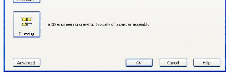
6 SolidWorks Components - DRAWINGS The third, and final component in SolidWorks is the Drawing. A drawing is the typical way to represent a 3D model such that any engineer (or manufacturer) can recreate your part. Drawings are important because they provide a standard way of sharing your design.

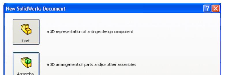
7 SolidWorks Let s Begin By default, no file is opened automatically when you start the program. To create a new file, click on File > New or click the New File icon in the main toolbar. This will open the New SolidWorks Document wizard.
8 SolidWorks Tour
9 SolidWorks Tour Let s begin by creating a new part. To do this, click on Part, then OK Once you do this, you will be brought into the modeling view which should open several toolbars and panes


10 SolidWorks Tour There are several important parts of the screen that needs to be identified before we continue. First, the left side of the First, the left side of the screen consists of several tabbed panes that provide very important information regarding your model.


11 SolidWorks Tour The first tab, called the Feature Manager, lists all features that have been created within your model. This tab is extremely important as it will be from here that you select and change features once they have been created.


12 SolidWorks Tour The second tab, called the Property Manager, allows you to adjust the properties of various entities either during construction, or once it has been created. Note that generally you will not need to manually change the tab on the manager window

13 SolidWorks Tour The third tab is called the Configuration Manager and is used to set up different view configurations such as exploded views or 3D section views. Usually this will be used once the part has been created and you wish to set up specific configurations for visualization.

14 SolidWorks Tour There may also be other tabs visible in the manager window. Generally any time you load an additional SolidWorks module (such as PhotoWorks, COSMOS Motion, COSMOS Works, etc.) it will create a new tab in this window.
15 SolidWorks Tour The next important feature of the interface is the dynamic Toolbar The dynamic Toolbar provides access to the most relevant, and frequently use commands in SolidWorks


16 SolidWorks Tour The last part of the interface which should be noted is the Task Pane on the right side of the screen. Using the Task Pane you can view content specific tasks such as importing standard geometry, file explorer, view palette, as well as any plug-in specific information.


17 SolidWorks Tour The last thing that needs to be shown is how to open the SolidWorks tutorials. They can be accessed by going to Help > SolidWorks Tutorials. The tutorials are very helpful and cover from the most basic features to more advanced analysis and assemblies
18 Now that we have explored the interface of SolidWorks, lets create a simple part step-bystep. For now, we are only going to concern ourselves with two types of features, Extruded Boss/Base and Extruded Cut.
19 We wish to model the following part:


20 What is Extrude? Extrude When you take a 2D area and push the design out into another dimension. A 2D area, for example, can be made into a 3D volume by extruding it out a specific distance, d. You can extrude to make a SOLID or you can extrude to make a CUT
21 There are MANY ways to EXTRUDE a surface This rectangle could be made from the side or bottom and extruded. We could make this rectangle and EXTRUDE it DOWN or UP You could EXTRUDE this rectangle and pull it to the left or right A rectangle could be made here on top of the first surface, then extruded down to make the cut.


22 Let s begin by selecting EXTRUDED Boss Base You should notice that your tab will change to property manager asking you to select a plane from the view.


23 Go ahead and select the horizontal plane shown. You should notice several things happen. 1. You switch to feature manager 2. You have sketch buttons on the dynamic toolbar 3. You view below is shown as TOP VIEW! You are looking down on top of the part.


24 Click on Rectangle. You should see your cursor change to a rectangle with a pencil which means you are sketching. Make a rectangle by dragging the mouse from one corner of the screen to the other. The size does not matter at this point.


25 If you hit escape, it will get you out of the rectangle TOOL and back to a normal cursor. We need DIMENSIONS to our rectangle however. At the bottom right of your screen you will see the figure above. Obviously, we are in the middle of our sketch but it also says, Under Defined. This means that there are parts of the sketch that are not defined according to location.


26 Click the bottom right point on the rectangle. You should be able to move this point around as its location is NOT defined. This point has degrees of freedom and is NOT constrained.


27 Let s save our work! Click on the small box next to the far right vertical line. Notice this box turns pink when clicked and that it has a vertical line in it. This means that this line is vertical and when you click on it you can move it left or right. The vertical lines can thus be moved up or down. Press the DELETE button, then click on the top right point. Notice the line is not defined as a vertical line anymore and the degrees of freedom are extended. The horizontal line still moves up or down, but notice the vertical line can be moved in any direction as you deleted the relationship.


28 You can add relations by clicking on a line, turns green. Line properties will appear and Line properties will appear and you can click on the VERTICAL button on the ADD RELATIONS windows to constrain the line to just the vertical direction.
29 To ZOOM you can use the mouse wheel or hit the Shift button and move mouse To PAN you use the Ctrl button and move mouse To fit a picture to a window simply press the f letter key on the keyboard to FIT.


30 Now we want to add specific dimensions to our drawing. Choose SMART DIMENSION on the dynamic toolbar. Click the bottom horizontal line of our rectangle and drag the dimension down. You can change the length of the line by using the slider bar or you can simply enter in 4 m in the box shown. Enter the value 4 then click the green check. Since the box is way too big, press f on the keyboard to fit. Then drag down the dimension so that you can see it after hitting escape.


31 Now using Smart Dimension again lets dimension the left vertical line. You may need to zoom or pan to view the line to click on. Modify the Length to be 2 units as shown in the original drawing.


32 Hit Escape, then f to fit. You should see a 2 x 4 rectangle. If you click the top right corner, you see you can move the entire rectangle. The entire drawing has yet to be defined in terms of its location relative to the plane,


33 To make the drawing fixed in the plane we can make one point coincident with the origin. Choose the top left point. Press CTRL, then select the origin. You will notice that under selected entries you have TWO items chosen. Under ADD RELATIONS you see Coincident. Choose this button and you will see the origin move to that point.
.")


34 Choose ok (green check). You should see all of the lines turn black. Click in the top right corner to EXIT the SKETCH.


35 When you exit the sketch you should see your dimensions and sketch in the plan you choose. An arrow will be located in the middle of your sketch. Click on the arrow and move upward.


36 As you drag it upward you should see the volume like structure shown. You can also EXTRUDE the shape down.


37 Drag the surface upward and release to select a volume. Under the properties manager we see several DIRECTIONS we can take this surface. Just choose BLIND. The D1 you see means depth and we see from our original picture we want a depth of 1. So enter 1, then click OK.

38 We now have our first SOLID piece. You should also notice we have a ton of new features available as well.


39 Solidworks is a PARAMETRIC design tool, meaning the edges are always driven by dimensions. So it is very important that your drawing be fully defined. Notice under features manager EXTRUDE now appears on the list. Double click on this or expand. You now see the design in terms of its dimensions.


40 Click on the width dimension and change the value from 2 to 3. Then click OK. Then click exit in the properties manager window. What happened? Notice the STOPLIGHT icon next to our sketch under features manager. What this means is that we have CHANGED the design but we have yet to REGENERATE the part.

41 Up on the dynamic toolbar you will see another stoplight icon, but this time it is a button. If you click this button it will REBUILD your part according to the changes you made. Notice the changes in your part. Go ahead and make changes to the other dimensions and rebuild to see the effect. THEN CHANGE THE DIMENSIONS BACK TO THE ORIGINAL DIMENSIONS of 4x2x1.

42 Lets go ahead and make this cut! To do this, we need to use what is called an EXTRUDED CUT.


43 Click extruded cut and notice what it is asking us in the properties manager tab. We want to select planar face which is the top surface as shown.


44 Click on that top surface. What happened? We are sketching on top of the plane but unfortunately we are not LOOKING at the plane itself. At the bottom left you see the VIEW selection. Trimetric is chosen now, but if you click the arrow beside it other options become available. Click the NORMAL TO view.
45 You should see now that you are looking directly DOWN at the plane. Click the rectangle button at the top and draw a rectangle of ANY SIZE within the surface of your plane.

46 If you hit escape, you see that the rectangle is certainly UNDER DEFINED just as our last one was. So lets go ahead an DIMENSION the rectangle using our given figure. When you are finished you basically have a rectangle than you can freely move within the planar surface.

47 Lets define the location of the rectangle. Click on the bottom left point and press the CTRL button to select MULTIPLE entries. Click on the bottom horizontal line.


48 Under properties manager notice the entries selected in pink. Choose coincident under ADD RELATIONS. Notice your point is now coincident with the bottom surface. Click OK in the properties manager window. Notice that your horizontal lines are black meaning they are fully defined. Try dragging the box


49 Clink on smart dimension and choose the right vertical line of our smaller rectangle then click on the vertical line of our planar surface edge. Then modify the distance to 1.50 Notice we see FULLY DEFINED at the bottom of our screen and that all of our lines are black meaning NO freedom of movement.


50 Click OK in properties manager then EXIT sketch in the top right. The view will not be seen from the point of view we can extrude so choose a different view from below. Choose ISOMETRIC.


51 From the property manager window under Cut-Extrude we can choose a direction. Choose THROUGH ALL as we want our cut to go all the way through. Then click OK. You should see the complete cut. Click and hold the mouse. You should be able to ROTATE the part in 3D space.


52 Suppose we change the ORIGINAL dimension of the planar surface length from 4m to 6m.In feature manager, click on the original extrude and then modify the length dimension to 6m. Then regenerate the part. You should see that the CUT is fixed at 1.5 m from the right edge. So the big question is.was THIS DESIGN INTENT? Did we really want this 1.5 m from the right or did we want the cut to be CENTERED?

53 Go ahead and change the length dimension back. In this case, the designer had the cut centered in the original drawing. Just keep DESIGN INTENT in mind when you are trying to decide HOW to model a part. Choose Extruded Boss/Base then choose the top planar surface. Then change your view to NORMAL TO so that you see the top planar surface as shown.

54 Now lets finish the top part. Choose rectangle, sketch it and dimension it according to the original drawing. But now lets try to center the sketch as we know it was the designer s intent to do this. RIGHT CLICK on the top horizontal line of your rectangle and a window will open. Choose SELECT MIDPOINT.


55 You should notice a point on your line. Press CTRL then CLICK on the top horizontal line of your planar surface. You should see them selected in properties manager in pink. Choose MIDPOINT in the ADD RELATIONS window. Your rectangle is now centered at the midpoint on the top edge of the planar surface.


56 EXIT your sketch then change your view to isometric. In properties manager, use BLIND for the direction and change the height(d1) to be 1.50 according to our original drawing. Choose select to see the finished part.


57 To establish DESIGN INTENT, change the original length dimension from 4 to 6m. Then rebuild the part. You should see the top part remain centered and the cut 1.5 m from the right edge.
SOLIDWORKS: Lesson 1 - Basics and Modeling. Introduction to Robotics
 SOLIDWORKS: Lesson 1 - Basics and Modeling Fundamentals Introduction to Robotics SolidWorks SolidWorks is a 3D solid modeling package which allows users to develop full solid models in a simulated environment
SOLIDWORKS: Lesson III Patterns & Mirrors. UCF Engineering
 SOLIDWORKS: Lesson III Patterns & Mirrors UCF Engineering Solidworks Review Last lesson we discussed several more features that can be added to models in order to increase their complexity. We are now
Introduction to SolidWorks Basics Materials Tech. Wood
 Introduction to SolidWorks Basics Materials Tech. Wood Table of Contents Table of Contents... 1 Book End... 2 Introduction... 2 Learning Intentions... 2 Modelling the Base... 3 Modelling the Front... 10
Introduction to SolidWorks for Technology. No1: Childs Toy
 Introduction to SolidWorks for Technology No1: Childs Toy Table of Contents Table of Contents... 1 Introduction... 2 Part Modelling: Cab... 3 Part Modelling: Base... 6 Part Modelling: Wheel... 12 Assembly:
Battery Holder. Chapter 9. Boat. A. Front Extrude. Step 1. Click File Menu > New, click Part and OK. SolidWorks 10 BATTERY HOLDER AA BOAT Page 9-1
 Chapter 9 Boat Battery Holder A. Front Extrude. Step 1. Click File Menu > New, click Part and OK. AA Step 2. Click Front (plane) in the Feature Manager and click Sketch from the Content toolbar, Fig. 1.
Body. Chapter 1. Simple Machines. A. New Part. Step 1. Click File Menu > New.
 Chapter 1 A. New Part. Step 1. Click File Menu > New. Simple Machines Body Step 2. Click Part from the list and click OK, Fig. 1. B. Sketch Construction Rectangle. Step 1. Click Right Plane in the Feature
Memo Block. This lesson includes the commands Sketch, Extruded Boss/Base, Extruded Cut, Shell, Polygon and Fillet.
 Commands Used New Part This lesson includes the commands Sketch, Extruded Boss/Base, Extruded Cut, Shell, Polygon and Fillet. Click File, New on the standard toolbar. Select Part from the New SolidWorks
Battery Holder 2 x AA
 Chapter 22 JSS Battery Holder 2 x AA A. Front Extrude. Step 1. Click File Menu > New, click Part Metric and OK. Step 2. Click Front Plane in the Feature Manager and click Sketch from the Context toolbar,
Chapter 2 Parametric Modeling Fundamentals
 2-1 Chapter 2 Parametric Modeling Fundamentals Create Simple Extruded Solid Models Understand the Basic Parametric Modeling Procedure Create 2-D Sketches Understand the Shape before Size Approach Use the
SolidWorks 2013 and Engineering Graphics
 SolidWorks 2013 and Engineering Graphics An Integrated Approach Randy H. Shih SDC PUBLICATIONS Schroff Development Corporation Better Textbooks. Lower Prices. www.sdcpublications.com Visit the following
Chair. Top Rail. on the Standard Views toolbar. (Ctrl-7) on the Weldments toolbar. at bottom left corner of display to deter- mine sketch plane.
 on the Weldments toolbar. at bottom left corner of display to deter- mine sketch plane.") Chapter 7 A. 3D Sketch. Step 1. If necessary, open your CHAIR file. Chair Top Rail Step 2. Click Isometric on the Standard Views toolbar. (Ctrl-7) Step 3. Zoom in around top of back leg, Fig. 1. To zoom,
Chapter 7 A. 3D Sketch. Step 1. If necessary, open your CHAIR file. Chair Top Rail Step 2. Click Isometric on the Standard Views toolbar. (Ctrl-7) Step 3. Zoom in around top of back leg, Fig. 1. To zoom,
SOLIDWORKS 2016 and Engineering Graphics
 SOLIDWORKS 2016 and Engineering Graphics An Integrated Approach Randy H. Shih SDC PUBLICATIONS Better Textbooks. Lower Prices. www.sdcpublications.com Powered by TCPDF (www.tcpdf.org) Visit the following
Speedway. Body. (S) on the Sketch toolbar. Fig. 1
 on the Sketch toolbar. Fig. 1") Chapter 1 A. New Part. Step 1. Click File Menu > New. Speedway Body Step 2. Click Part from the list and click OK, Fig. 1. B. Sketch Construction Rectangle. Step 1. Click Right Plane in the Feature Manager
Chapter 1 A. New Part. Step 1. Click File Menu > New. Speedway Body Step 2. Click Part from the list and click OK, Fig. 1. B. Sketch Construction Rectangle. Step 1. Click Right Plane in the Feature Manager
Panel. Chapter 16. Solar Car. A. Sketch. Step 1. Click File Menu > New, click Part and OK. B. Save as "PANEL". Step 1. Click File Menu > Save As.
 Chapter 16 Solar Car Panel A. Sketch. Step 1. Click File Menu > New, click Part and OK. Step 2. Click Top Plane in the Feature Manager and click Sketch from the Content toolbar, Fig. 1. Step 3. Click Center
ME009 Engineering Graphics and Design CAD 1. 1 Create a new part. Click. New Bar. 2 Click the Tutorial tab. 3 Select the Part icon. 4 Click OK.
 PART A Reference: SolidWorks CAD Student Guide 2014 2 Lesson 2: Basic Functionality Active Learning Exercises Creating a Basic Part Use SolidWorks to create the box shown at the right. The step-by-step
Tail Hook. Chapter 14. Airplane. A. Construction Rectangle. Step 1. Click File Menu > New, click Part and OK.
 Chapter 14 Airplane Tail Hook A. Construction Rectangle. Step 1. Click File Menu > New, click Part and OK. Step 2. Click Right (plane) in the Feature Manager and click Sketch from the Content toolbar,
Boat. Battery Holder AA
 Chapter 9 Boat Battery Holder AA A. Front Extrude. Step 1. Click File Menu > New, click Part and OK. Step 2. Click Front Plane in the Feature Manager and click Sketch context toolbar, Fig. 1. Step 3. Click
Simple Machines. Body. Step 4. Start at Origin and sketch the 8 lines, Fig. 2. Fig. 1. Origin
 Chapter 1 Simple Machines Body A. Sketch. Step 1. Click File Menu > New, click Part and OK. Step 2. Click Right Plane in the Feature Manager and click Sketch on the context toolbar, Fig. 1. Step 3. Click
Solar Car. Chassis. in the Feature Manager and click Sketch from the Content toolbar, Fig. 2. Origin. on the Command Manager toolbar. Fig.
 Chapter 1 A. New Part. Step 1. Click File Menu > New. Solar Car Chassis Step 2. Click Part from the list and click OK, Fig. 1. B. Sketch Chassis. Step 1. Click Right Plane in the Feature Manager and click
Skateboard. Hanger. in the Feature Manager and click Sketch on the Context toolbar, Fig. 1. Fig. 2
 Chapter 3 Skateboard Hanger A. Sketch1 Lines. Step 1. Click File Menu > New, click Part Metric and OK. Step 2. Click Right Plane in the Feature Manager and click Sketch on the Context toolbar, Fig. 1.
The Fundamentals of SolidWorks Featuring the VEXplorer robot with over 40 integrated stand-alone tutorials
 INSIDE: Tutorial Model Files On CD The Fundamentals of SolidWorks 2007 Featuring the VEXplorer robot with over 40 integrated stand-alone tutorials David C. Planchard & Marie P. Planchard, CSWP SDC PUBLICATIONS
Delta Dart. Propeller. in the Feature Manager and click Sketch from the Content toolbar, Fig. 1. on the Sketch toolbar.
 Chapter 8 Delta Dart Propeller A. Base for Blade. Step 1. Click File Menu > New, click Part Metric and OK. Step 2. Click Top Plane in the Feature Manager and click Sketch from the Content toolbar, Fig.
Propeller. Chapter 13. Airplane. A. Base for Blade. Step 1. Click File Menu > New, click Part and OK.
 Chapter 13 Airplane Propeller A. Base for Blade. Step 1. Click File Menu > New, click Part and OK. Step 2. Click Top Plane in the Feature Manager and click Sketch toolbar, Fig. 1. from the Content Step
Autodesk Inventor - Basics Tutorial Exercise 1
 Autodesk Inventor - Basics Tutorial Exercise 1 Launch Inventor Professional 2015 1. Start a New part. Depending on how Inventor was installed, using this icon may get you an Inch or Metric file. To be
TUTORIAL 2. OBJECTIVE: Use SolidWorks/COSMOS to model and analyze a cattle gate bracket that is subjected to a force of 100,000 lbs.
 TUTORIAL 2 OBJECTIVE: Use SolidWorks/COSMOS to model and analyze a cattle gate bracket that is subjected to a force of 100,000 lbs. GETTING STARTED: 1. Open the SolidWorks program. 2. Open a new part file.
Rocket 1. Fin. in the Feature Manager and click Sketch from the Content toolbar, Fig. 1. (L) on the Sketch toolbar. Fig. 1. Fig. 2
 on the Sketch toolbar. Fig. 1. Fig. 2") Chapter 2 Rocket 1 Fin A. Sketch. Step 1. Click File Menu > New, click Part and OK. Step 2. Click Right Plane in the Feature Manager and click Sketch from the Content toolbar, Fig. 1. Step 3. Click Line
Chapter 2 Rocket 1 Fin A. Sketch. Step 1. Click File Menu > New, click Part and OK. Step 2. Click Right Plane in the Feature Manager and click Sketch from the Content toolbar, Fig. 1. Step 3. Click Line
Fuselage and Sharks Tooth
 Chapter 4 Glider Fuselage and Sharks Tooth A. Save as "FUSELAGE". Step 1. Open your FUSELAGE BLANK file. Step 2. Click File Menu > Save As. Step 3. Key-in FUSELAGE for the filename and press ENTER. B.
SolidWorks 2½D Parts
 SolidWorks 2½D Parts IDeATe Laser Micro Part 1b Dave Touretzky and Susan Finger 1. Create a new part In this lab, you ll create a CAD model of the 2 ½ D key fob below to make on the laser cutter. Select
H Stab and V Stab. Chapter 6. Glider. A. Open and Save as "H STAB". Step 1. Open your STABILIZER BLANK file.
 Chapter 6 Glider H Stab and V Stab A. Open and Save as "H STAB". Step 1. Open your STABILIZER BLANK file. Step 2. Click File Menu > Save As. Step 3. Key-in H STAB for the filename and press ENTER. B. Sketch
SolidWorks Intro Part 1b
 SolidWorks Intro Part 1b Dave Touretzky and Susan Finger 1. Create a new part We ll create a CAD model of the 2 ½ D key fob below to make on the laser cutter. Select File New Templates IPSpart If the SolidWorks
Chapter 4 Feature Design Tree
 4-1 Chapter 4 Feature Design Tree Understand Feature Interactions Use the FeatureManager Design Tree Modify and Update Feature Dimensions Perform History-Based Part Modifications Change the Names of Created
F-1 Car. Blank. in the Feature Manager and click Sketch from the Content toolbar, Fig. 3. Origin. on the Features toolbar.
 Chapter 1 A. New Metric Part. Step 1. Click File Menu > New. F-1 Car Blank Step 2. Click Part Metric from the list of templates and click OK, Fig. 1. If you are not using SOLIDWORKS templates (you should
F1 Car. Wheel. in the Feature Manager and click Sketch on the Context toolbar, Fig. 1. (S) on the
 on the") Chapter 3 F1 Car Wheel A. Sketch Lines. Step 1. Click File Menu > New, click Part Metric and OK. Step 2. Click Front Plane in the Feature Manager and click Sketch on the Context toolbar, Fig. 1. Step 3.
Chapter 3 F1 Car Wheel A. Sketch Lines. Step 1. Click File Menu > New, click Part Metric and OK. Step 2. Click Front Plane in the Feature Manager and click Sketch on the Context toolbar, Fig. 1. Step 3.
Glider. Clay. Fig. 1 Side face. Step 5. In the Convert Entities Property Manager: click side face, Fig. 3 click OK twice, Fig. 3. Fig. 3.
 Chapter 9 A. Open Assembly File. Step 1. Open your GLIDER ASSEMBLY file. Glider Clay B. New Component Part. Step 1. Click Insert Menu > Component > New Part. Step 2. Click the side face of the Fuselage,
SolidWorks 2015 User Interface
 SolidWorks 2015 User Interface SolidWorks a Dassault Systèmes Product Starting SolidWorks 1) On the desktop, double-click or from the start menu select: All Programs SOLIDWORKS 2015 SOLIDWORKS 2015. 2)
Body. Chapter 2. CO2 Rail Car E. A. Save as "BODY RAIL E". Step 1. Open your BLANK file.
 Chapter 2 A. Save as "BODY RAIL E". Step 1. Open your BLANK file. Step 2. Click File Menu > Save As. Step 3. Key-in BODY RAIL E for the filename and press ENTER. CO2 Rail Car E Body B. Appearance. Step
An Introduction to Autodesk Inventor 2010 and AutoCAD Randy H. Shih SDC PUBLICATIONS. Schroff Development Corporation
 An Introduction to Autodesk Inventor 2010 and AutoCAD 2010 Randy H. Shih SDC PUBLICATIONS Schroff Development Corporation www.schroff.com 2-1 Chapter 2 Parametric Modeling Fundamentals Create Simple Extruded
Skateboard. Hanger. in the Feature Manager and click Sketch. (S) on the Sketch. Line
 on the Sketch. Line") Chapter 3 Skateboard Hanger A. Sketch 1. Step 1. Click File Menu > New, click Part Metric and OK. Step 2. Click Right Plane from the Content toolbar, Fig. 1. in the Feature Manager and click Sketch Step
Chapter 3 Skateboard Hanger A. Sketch 1. Step 1. Click File Menu > New, click Part Metric and OK. Step 2. Click Right Plane from the Content toolbar, Fig. 1. in the Feature Manager and click Sketch Step
Assembly Motion Study
 Penny Hockey Chapter 10 Assembly Motion Study A. Rename Penny Mate. Step 1. Open your PENNY HOCKEY ASSEMBLY file. Step 2. Expand Mates in the Feature Manager and select the last Mate, Fig. 1. This should
Autodesk Inventor 2019 and Engineering Graphics
 Autodesk Inventor 2019 and Engineering Graphics An Integrated Approach Randy H. Shih SDC PUBLICATIONS Better Textbooks. Lower Prices. www.sdcpublications.com Powered by TCPDF (www.tcpdf.org) Visit the
Terminal. Chapter 16. E-Car. A. Component from Design Library. SOLIDWORKS 17 Terminal E-CAR Page 16-1
 Chapter 16 E-Car Terminal A. Component from Design Library. Step 1. Click the Design Library tab in the Task Pane (right side of graphics area), Fig. 1. Step 2. Expand routing and click electrical folder
Blank. Chapter 1. CO2 Rail Car. A. New Metric Part. Step 1. Click File Menu > New. B. Body. Step 1. Click Right Plane
 Chapter 1 A. New Metric Part. Step 1. Click File Menu > New. CO2 Rail Car Blank Step 2. Click Part Metric from the list and click OK, Fig. 1. If you are not using SolidWorks templates (you should be),
Simple Machines. Wheel. in the Feature Manager and click Sketch. on the Command Manager toolbar.
 Chapter 3 Simple Machines Wheel A. Wheel. Step 1. Click File Menu > New, click Part and OK. Step 2. Click Right Plane from the Content toolbar, Fig. 1. in the Feature Manager and click Sketch Step 3. Click
Parametric Modeling Design and Modeling 2011 Project Lead The Way, Inc.
 Parametric Modeling Design and Modeling 2011 Project Lead The Way, Inc. 3D Modeling Steps - Sketch Step 1 Sketch Geometry Sketch Geometry Line Sketch Tool 3D Modeling Steps - Constrain Step 1 Sketch Geometry
Parametric Modeling with. Autodesk Fusion 360. First Edition. Randy H. Shih SDC. Better Textbooks. Lower Prices.
 Parametric Modeling with Autodesk Fusion 360 First Edition Randy H. Shih SDC PUBLICATIONS Better Textbooks. Lower Prices. www.sdcpublications.com Powered by TCPDF (www.tcpdf.org) Visit the following websites
SolidWorks 2009 & DCG Student Assignment
 SolidWorks 2009 & DCG Student Assignment RD10 DCG Design & Communication Graphics 1 SolidWorks 2009 & DCG Student Assignment Table of Contents Focus of the lesson. 3 Getting Started Modelling the TV Plate
Clay. Chapter 9. Glider. A. Open Assembly File. Step 1. Open your GLIDER ASSEMBLY file.
 Chapter 9 A. Open Assembly File. Step 1. Open your GLIDER ASSEMBLY file. Glider Clay B. New Component Part. Step 1. Click Insert Menu > Component > New Part. C. Sketch. Step 1. Click the side face of the
Lesson 2 Constructive Solid Geometry Concept. Parametric Modeling with I-DEAS 2-1
 Lesson 2 Constructive Solid Geometry Concept Parametric Modeling with I-DEAS 2-1 2-2 Parametric Modeling with I-DEAS Introduction In the 1980s, one of the main advancements in Solid Modeling was the development
Parametric Modeling. With. Autodesk Inventor. Randy H. Shih. Oregon Institute of Technology SDC PUBLICATIONS
 Parametric Modeling With Autodesk Inventor R10 Randy H. Shih Oregon Institute of Technology SDC PUBLICATIONS Schroff Development Corporation www.schroff.com www.schroff-europe.com 2-1 Chapter 2 Parametric
CO2 Rail Car. Wheel Rear Px. on the Command Manager toolbar.
 Chapter 6 CO2 Rail Car Wheel Rear Px A. Sketch Construction Lines. Step 1. Click File Menu > New, click Part Metric and OK. Step 2. Click Front (plane) in the Feature Manager (left panel), Fig. 1. Step
Glider. Wing. Top face click Sketch. on the Standard Views. (S) on the Sketch toolbar.
 on the Sketch toolbar.") Chapter 5 Glider Wing 4 Panel Tip A. Open and Save As "WING 4 PANEL". Step 1. Open your WING BLANK file. Step 2. Click File Menu > Save As. Step 3. Key-in WING 4 PANEL for the filename and press ENTER.
Chapter 5 Glider Wing 4 Panel Tip A. Open and Save As "WING 4 PANEL". Step 1. Open your WING BLANK file. Step 2. Click File Menu > Save As. Step 3. Key-in WING 4 PANEL for the filename and press ENTER.
Nose Cone. Chapter 4. Rocket 3D Print. A. Revolve. Step 1. Click File Menu > New, click Part and OK. SOLIDWORKS 16 Nose Cone ROCKET 3D PRINT Page 4-1
 Chapter 4 Rocket 3D Print Nose Cone A. Revolve. Step 1. Click File Menu > New, click Part and OK. Step 2. Click Front Plane in the Feature Manager and click Sketch on the content toolbar, Fig. 1. Step
Solidworks 2006 Surface-modeling
 Solidworks 2006 Surface-modeling (Tutorial 2-Mouse) Surface-modeling Solid-modeling A- 1 Assembly Design Design with a Master Model Surface-modeling Tutorial 2A Import 2D outline drawing into Solidworks2006
Chapter 2 Parametric Modeling Fundamentals
 2-1 Chapter 2 Parametric Modeling Fundamentals Create Simple Extruded Solid Models Understand the Basic Parametric Modeling Procedure Create 2-D Sketches Understand the "Shape before Size" Approach Use
An Introduction to Autodesk Inventor 2013 and AutoCAD
 An Introduction to Autodesk Inventor 2013 and AutoCAD 2013 Randy H. Shih SDC PUBLICATIONS Schroff Development Corporation Better Textbooks. Lower Prices. www.sdcpublications.com Visit the following websites
CO 2 Shell Car. Body. in the Feature Manager and click Sketch from the context toolbar, Fig. 1. on the Standard Views toolbar.
 CO 2 Shell Car Chapter 2 Body A. Save as "BODY". Step 1. If necessary, open your BLANK file. Step 2. Click File Menu > Save As. Step 3. Key-in BODY for the filename and press ENTER. B. FRONT Wheel Shell.
SolidWorks 2001 Getting Started
 SolidWorks 2001 Getting Started 1995-2001, SolidWorks Corporation 300 Baker Avenue Concord, Massachusetts 01742 USA All Rights Reserved. U.S. Patent 5,815,154 SolidWorks Corporation is a Dassault Systemes
Lesson 1 Parametric Modeling Fundamentals
 1-1 Lesson 1 Parametric Modeling Fundamentals Create Simple Parametric Models. Understand the Basic Parametric Modeling Process. Create and Profile Rough Sketches. Understand the "Shape before size" approach.
Solid Modeling SolidWorks Layout. ENGR 1182 SolidWorks 01
 Solid Modeling SolidWorks Layout ENGR 1182 SolidWorks 01 Solid Modeling In The Real World Mechanical and Aerospace engineers need solid models of jet engine components and assemblies to do analysis on
Engineering. Statics Labs SDC. with SOLIDWORKS Motion Includes. Huei-Huang Lee. Better Textbooks. Lower Prices.
 Engineering Includes Video demonstrations of the exercises in the book Statics Labs with SOLIDWORKS Motion 2015 Huei-Huang Lee Multimedia Disc SDC PUBLICATIONS Better Textbooks. Lower Prices. www.sdcpublications.com
Workshop name: CAD Strategies for 3D Printing
 Page 1 of 9 Workshop name: CAD Strategies for 3D Printing Presented by James Novak: Griffith University Lecturer, PhD Candidate, Industrial Designer Activity 1 Parametric Test Models Discussion: Additive
An Introduction to Autodesk Inventor 2012 and AutoCAD Randy H. Shih SDC PUBLICATIONS. Schroff Development Corporation
 An Introduction to Autodesk Inventor 2012 and AutoCAD 2012 Randy H. Shih SDC PUBLICATIONS www.sdcpublications.com Schroff Development Corporation Visit the following websites to learn more about this book:
SolidWorks Implementation Guides. User Interface
 SolidWorks Implementation Guides User Interface Since most 2D CAD and SolidWorks are applications in the Microsoft Windows environment, tool buttons, toolbars, and the general appearance of the windows
3D Design with 123D Design
 3D Design with 123D Design Introduction: 3D Design involves thinking and creating in 3 dimensions. x, y and z axis Working with 123D Design 123D Design is a 3D design software package from Autodesk. A
Parametric Modeling with UGS NX 4
 Parametric Modeling with UGS NX 4 Randy H. Shih Oregon Institute of Technology SDC PUBLICATIONS Schroff Development Corporation www.schroff.com www.schroff-europe.com 2-1 Chapter 2 Parametric Modeling
Chapter 1. SolidWorks Overview
 Chapter 1 SolidWorks Overview Objectives: When you complete this chapter you will: Have a good background knowledge of SolidWorks Have learnt how to start a SolidWorks session Understand the SolidWorks
Parametric Modeling with SolidWorks
 Parametric Modeling with SolidWorks 2012 LEGO MINDSTORMS NXT Assembly Project Included Randy H. Shih Paul J. Schilling SDC PUBLICATIONS Schroff Development Corporation Better Textbooks. Lower Prices. www.sdcpublications.com
SOLIDWORKS 2018 Reference Guide
 SOLIDWORKS 2018 Reference Guide A comprehensive reference guide with over 250 standalone tutorials David C. Planchard, CSWP, SOLIDWORKS Accredited Educator SDC PUBLICATIONS Better Textbooks. Lower Prices.
Fig. 1. Fig. 1. on the Standard Views toolbar. SolidWorks ASSEMBLY AIRPLANE Page 8-1
 Chapter 8 Airplane Assembly A. Insert Set of Parts. Step 1. Click File Menu > New, click Assembly and OK. Step 2. Click View Menu > Origins to display the origin. Step 3. Click Keep Visible in the Property
SOLIDWORKS Parametric Modeling with SDC. Covers material found on the CSWA exam. Randy H. Shih Paul J. Schilling
 Parametric Modeling with SOLIDWORKS 2015 Covers material found on the CSWA exam Randy H. Shih Paul J. Schilling SDC PUBLICATIONS Better Textbooks. Lower Prices. www.sdcpublications.com Powered by TCPDF
e b f SOLIDWORKS ESSENTIALS 1) SOLIDWORKS USER INTERFACE SUBJECT: USER INTERFACE KEYWORDS: ESSENTIALS/ FUNDAMENTALS a) The Graphics Area
 SOLIDWORKS USER INTERFACE SUBJECT: USER INTERFACE KEYWORDS: ESSENTIALS/ FUNDAMENTALS a) The Graphics Area") SUBJECT: USER INTERFACE KEYWORDS: ESSENTIALS/ FUNDAMENTALS SOLIDWORKS ESSENTIALS The aim of this document is to provide additional reference material to allow new users of SolidWorks to navigate through
SUBJECT: USER INTERFACE KEYWORDS: ESSENTIALS/ FUNDAMENTALS SOLIDWORKS ESSENTIALS The aim of this document is to provide additional reference material to allow new users of SolidWorks to navigate through
Wheel GT-F. Chapter 5. CO2 Shell Car. A. Sketch. Step 1. Click File Menu > New, click Part Metric and OK.
 Chapter 5 CO2 Shell Car Wheel GT-F A. Sketch. Step 1. Click File Menu > New, click Part Metric and OK. Step 2. Click Front Plane in the Feature Manager and click Sketch on the context toolbar, Fig. 1.
SOLIDWORKS 2016: A Power Guide for Beginners and Intermediate Users
 SOLIDWORKS 2016: A Power Guide for Beginners and Intermediate Users The premium provider of learning products and solutions www.cadartifex.com Table of Contents Dedication... 3 Preface... 15 Part 1. Introducing
Autodesk Inventor Design Exercise 2: F1 Team Challenge Car Developed by Tim Varner Synergis Technologies
 Autodesk Inventor Design Exercise 2: F1 Team Challenge Car Developed by Tim Varner Synergis Technologies Tim Varner - 2004 The Inventor User Interface Command Panel Lists the commands that are currently
CO2 Car Assembly. in the Property Manager to place the part at the origin, Fig. 1. on the Assemblies toolbar. SolidWorks Assembly CO2 CAR Page 8-1
 Chapter 8 CO2 Car Assembly A. Insert Axles and Wheels. Step 1. Click File Menu > New, click Assembly Metric and OK. Step 2. Click Keep Visible in the Property Manager, Fig. 1. Step 3. Click Browse in the
Parametric Modeling. with. Autodesk Inventor Randy H. Shih. Oregon Institute of Technology SDC
 Parametric Modeling with Autodesk Inventor 2009 Randy H. Shih Oregon Institute of Technology SDC PUBLICATIONS Schroff Development Corporation www.schroff.com Better Textbooks. Lower Prices. 2-1 Chapter
Delta IV Heavy. Interstage. in the Feature Manager and click Sketch on the Context toolbar, Fig. 1. on the Command Man- on the Features
 Chapter 4 Delta IV Heavy Interstage A. Sketch Circles. Step 1. Click File Menu > New, click Part and OK. Step 2. Click Top Plane in the Feature Manager and click Sketch on the Context toolbar, Fig. 1.
Lesson 1: Creating T- Spline Forms. In Samples section of your Data Panel, browse to: Fusion 101 Training > 03 Sculpt > 03_Sculpting_Introduction.
 3.1: Sculpting Sculpting in Fusion 360 allows for the intuitive freeform creation of organic solid bodies and surfaces by leveraging the T- Splines technology. In the Sculpt Workspace, you can rapidly
SOLIDWORKS 2016 in 5 Hours with Video Instruction
 SOLIDWORKS 2016 in 5 Hours with Video Instruction David C. Planchard, CSWP, SOLIDWORKS Accredited Educator SDC PUBLICATIONS Better Textbooks. Lower Prices. www.sdcpublications.com ACCESS CODE UNIQUE CODE
Parametric Modeling with SOLIDWORKS 2017
 Parametric Modeling with SOLIDWORKS 2017 NEW Contains a new chapter on 3D printing Covers material found on the CSWA exam Randy H. Shih Paul J. Schilling SDC PUBLICATIONS Better Textbooks. Lower Prices.
Boat. Hull. Step 4. Sketch point directly above the Origin, Fig. 2. Use the inferencing line, the dotted line that appears when you sketch the point.
 Chapter 1 Boat Hull A. Sketch. Step 1. Click File Menu > New, click Part and OK. Step 2. Click Front Plane in the Feature Manager and click Sketch on the content toolbar, Fig. 1. Step 3. Click Point on
Airplane Assembly. SolidWorks 10 ASSEMBLY AIRPLANE Page 9-1
 Chapter 9 A. Insert Parts. Airplane Assembly Step 1. Click File Menu > New, click Assembly and OK. Step 2. Click Keep Visible in the Property Manager, Fig. 1. Step 3. Click Browse in the Property Manager,
JSS. Ping Pong Ball. in the Feature Manager and click Sketch on the Context toolbar, Fig. 1. on the Sketch toolbar.
 Chapter 18 JSS Ping Pong Ball A. Half Circle Sketch. Step 1. Click File Menu > New, click Part Metric and OK. Step 2. Click Front Plane in the Feature Manager and click Sketch on the Context toolbar, Fig.
Changes from SolidWorks 2003 to SolidWorks 2004
 Changes from SolidWorks 2003 to SolidWorks 2004 The changes from SolidWorks 2003 to SolidWorks 2004 are primarily cosmetic. Consequently, it is quite easy to use the current edition of Learning SolidWorks
Parametric Modeling with NX 12
 Parametric Modeling with NX 12 NEW Contains a new chapter on 3D printing Randy H. Shih SDC PUBLICATIONS Better Textbooks. Lower Prices. www.sdcpublications.com Powered by TCPDF (www.tcpdf.org) Visit the
Learning. Modeling, Assembly and Analysis SOLIDWORKS Randy H. Shih SDC. Better Textbooks. Lower Prices.
 Learning SOLIDWORKS 2016 Modeling, Assembly and Analysis Randy H. Shih SDC PUBLICATIONS Better Textbooks. Lower Prices. www.sdcpublications.com Powered by TCPDF (www.tcpdf.org) Visit the following websites
Autodesk Inventor 2018
 Learning Autodesk Inventor 2018 Modeling, Assembly and Analysis Randy H. Shih SDC PUBLICATIONS Better Textbooks. Lower Prices. www.sdcpublications.com Powered by TCPDF (www.tcpdf.org) Visit the following
A Guide to Autodesk Maya 2015
 A Guide to Autodesk Maya 2015 Written by Mitchell Youngerman Table of Contents Layout of Toolbars...pg 1 Creating Objects...pg 2 Selecting & Deselecting Objects...pg 3 Changing Perspective... pg 4 Transforming
Mastercam X6 for SolidWorks Toolpaths
 Chapter 14 Spinning Top Mastercam X6 for SolidWorks Toolpaths A. Insert Handle in New Assembly. Step 1. Click File Menu > New, click Assembly and OK. Step 2. Click Browse in the Property Manager, Fig.
Tools for Design. with VEX Robot Kit: Randy H. Shih Oregon Institute of Technology SDC PUBLICATIONS
 Tools for Design with VEX Robot Kit: AutoCAD 2011 and Autodesk Inventor 2011 2D Drawing 3D Modeling Hand Sketching Randy H. Shih Oregon Institute of Technology INSIDE: SUPPLEMENTAL FILES ON CD SDC PUBLICATIONS
Visit the following websites to learn more about this book:
 Assembly Modeling Model Files Initial and Final Solutions! with SolidWorks 2012 For the SolidWorks user who needs to understand Assembly modeling By Planchard & Planchard CSWP SDC SSoolliiddW Woorrkkss
Tutorial Second Level
 AutoCAD 2018 Tutorial Second Level 3D Modeling Randy H. Shih SDC PUBLICATIONS Better Textbooks. Lower Prices. www.sdcpublications.com Powered by TCPDF (www.tcpdf.org) Visit the following websites to learn
Tools for Design. Using AutoCAD 2015 and Autodesk Inventor 2015 SDC. Hand Sketching, 2D Drawing and 3D Modeling. Randy H. Shih
 Tools for Design Using AutoCAD 2015 and Autodesk Inventor 2015 Hand Sketching, 2D Drawing and 3D Modeling Randy H. Shih SDC PUBLICATIONS Better Textbooks. Lower Prices. www.sdcpublications.com Powered
Tools for Design. A practical guide to 2D Drawing, Sketching, 3D Parametric Modeling and Finite Element Analysis
 Tools for Design Using AutoCAD 2011, Autodesk Inventor 2011, and LEGO MINDSTORMS NXT & TETRIX A practical guide to 2D Drawing, Sketching, 3D Parametric Modeling and Finite Element Analysis INSIDE: SUPPLEMENTAL
Structural & Thermal Analysis using the ANSYS Workbench Release 11.0 Environment. Kent L. Lawrence
 ANSYS Workbench Tutorial Structural & Thermal Analysis using the ANSYS Workbench Release 11.0 Environment Kent L. Lawrence Mechanical and Aerospace Engineering University of Texas at Arlington SDC PUBLICATIONS
with Video Instruction
 SOLIDWORKS 2017 Tutorial with Video Instruction A Step-by-Step Project Based Approach Utilizing 3D Solid Modeling David C. Planchard, CSWP, SOLIDWORKS Accredited Educator SDC PUBLICATIONS Better Textbooks.
Learning Autodesk Inventor 2014
 Learning Autodesk Inventor 2014 Modeling, Assembly and Analysis Randy H. Shih SDC P U B L I C AT I O N S Better Textbooks. Lower Prices. www.sdcpublications.com Visit the following websites to learn more
SolidWorks 2008 Tutorial. with MultiMedia CD. A Step-by-Step Project Based Approach Utilizing 3D Solid Modeling
 INSIDE: MultiMedia CD An audio/visual presentation of the tutorial projects with MultiMedia CD A Step-by-Step Project Based Approach Utilizing 3D Solid Modeling David C. Planchard & Marie P. Planchard
Delta Dart. Socket. (L) on the Sketch toolbar. Fig. 1. (S) on the Sketch toolbar. on the Sketch toolbar. on the Standard Views toolbar.
 on the Sketch toolbar. Fig. 1. (S) on the Sketch toolbar. on the Sketch toolbar. on the Standard Views toolbar.") Chapter 6 Delta Dart Socket A. Sketch. Step 1. Click File Menu > New, click Part Metric and OK. Step 2. Click Front Plane in the Feature Manager and click Sketch from the Content toolbar, Fig. 1. Step
Chapter 6 Delta Dart Socket A. Sketch. Step 1. Click File Menu > New, click Part Metric and OK. Step 2. Click Front Plane in the Feature Manager and click Sketch from the Content toolbar, Fig. 1. Step
Structural & Thermal Analysis Using the ANSYS Workbench Release 12.1 Environment
 ANSYS Workbench Tutorial Structural & Thermal Analysis Using the ANSYS Workbench Release 12.1 Environment Kent L. Lawrence Mechanical and Aerospace Engineering University of Texas at Arlington SDC PUBLICATIONS