SolidWorks Tutorial 1 Axis
|
|
|
- Bertha Watts
- 6 years ago
- Views:
Transcription


1 SolidWorks Tutorial 1 Axis Preparatory Vocational Training and Advanced Vocational Training To be used with SolidWorks Educational Edition Release
2 , Dassault Systèmes SolidWorks Corp. 300 Baker Avenue Concord, Massachusetts USA All Rights Reserved U.S. Patents 5,815,154; 6,219,049; 6,219,055 Dassault Systèmes SolidWorks Corp. is a Dassault Systèmes S.A. (Nasdaq:DASTY) company. The information and the software discussed in this document are subject to change without notice and should not be considered commitments by Dassault Systèmes SolidWorks Corp. No material may be reproduced or transmitted in any form or by any means, electronic or mechanical, for any purpose without the express written permission of Dassault Systèmes SolidWorks Corp. The software discussed in this document is furnished under a license and may be used or copied only in accordance with the terms of this license. All warranties given by Dassault Systèmes SolidWorks Corp. as to the software and documentation are set forth in the Dassault Systèmes SolidWorks Corp. License and Subscription Service Agreement, and nothing stated in, or implied by, this document or its contents shall be considered or deemed a modification or amendment of such warranties. SolidWorks is a registered trademark of Dassault Systèmes SolidWorks Corp. SolidWorks 2009 is a product name of Dassault Systèmes SolidWorks Corp. FeatureManager is a jointly owned registered trademark of Dassault Systèmes SolidWorks Corp. Feature Palette and PhotoWorks are trademarks of Dassault Systèmes SolidWorks Corp. ACIS is a registered trademark of Spatial Corporation. FeatureWorks is a registered trademark of Geometric Software Solutions Co. Limited. GLOBEtrotter and FLEXlm are registered trademarks of Globetrotter Software, Inc. Other brand or product names are trademarks or registered trademarks of their respective holders. COMMERCIAL COMPUTER SOFTWARE - PROPRIETARY U.S. Government Restricted Rights. Use, duplication, or disclosure by the government is subject to restrictions as set forth in FAR (Commercial Computer Software - Restricted Rights), DFARS (Commercial Computer Software and Commercial Computer Software Documentation), and in the license agreement, as applicable. Contractor/Manufacturer: Dassault Systèmes SolidWorks Corp., 300 Baker Avenue, Concord, Massachusetts USA Portions of this software are copyrighted by and are the property of Electronic Data Systems Corporation or its subsidiaries, copyright 2009 Portions of this software 1999, ComponentOne Portions of this software D-Cubed Limited. Portions of this product are distributed under license from DC Micro Development, Copyright DC Micro Development, Inc. All Rights Reserved. Portions ehelp Corporation. All Rights Reserved. Portions of this software Geometric Software Solutions Co. Limited. Portions of this software mental images GmbH & Co. KG Portions of this software Microsoft Corporation. All Rights Reserved. Portions of this software 2009, SIMULOG. Portions of this software Spatial Corporation. Portions of this software 2009, Structural Research & Analysis Corp. Portions of this software Tech Soft America. Portions of this software Viewpoint Corporation. Portions of this software , Visual Kinematics, Inc. All Rights Reserved. SolidWorks Benelux developed this tutorial for self-training with the SolidWorks 3D CAD program. Any other use of this tutorial or parts of it is prohibited. For questions, please contact SolidWorks Benelux. Contact information is printed on the last page of this tutorial. Initiative: Kees Kloosterboer (SolidWorks Benelux) Educational Advisor: Jack van den Broek (Vakcollege Dr. Knippenberg) Realization: Arnoud Breedveld (PAZ Computerworks) 2

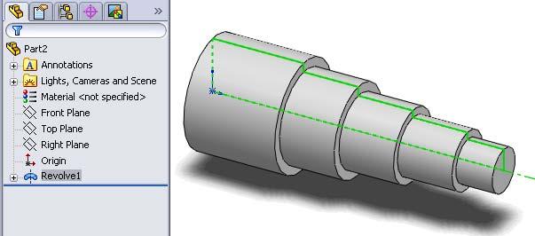
3 Axis This first exercise provides an introduction to SolidWorks software. First, we will design and draw a simple part: an axis with different diameters. You will learn how to work with the software and learn its basic principles. You will find out how to add and remove material. How to do it Before you start drawing in SolidWorks, you must have a work plan of how to proceed. In most instances, you will produce a part in SolidWorks in the same way as you would create it in the workshop. Therefore, for this assignment you have to go through the following steps: 1. Create an axis of Ø30 x Cut the material in order to create the different diameters. At the turning machine, you would have to perform several extra steps to achieve the desired accuracy. For example, you would not be able to remove all the material in a single turn. In SolidWorks, this is not the case. 3


4 1 Start up SolidWorks. Do this by locating SolidWorks in the Windows Start menu of. There may even be a shortcut on your desktop that you can use. After startup, you will see an image like the one at the right side of this page. The screen may look a bit different; this depends on the default settings of the software and/or the computer you are using. 2 No file has been opened yet. To create a file, click on the first button on the toolbar: New. 3 Next, you will see a new screen (see right image). Click on Part and then click OK. 4


5 4 In the left column, click on Right Plane. The plane turns green: We will make a drawing in this plane. 5 Click on Sketch. New functions and possibilities appear, and you can use them to make a drawing. 6 Click on Circle, in order to draw a circle. 5


6 7 At this point, the plane turns towards you, so you can have a good view on what you are drawing. In the middle you see a point with red arrows; this is what is called the origin or the zero marker. Put the cursor directly at the origin: it should look like the image on the right. Click once with the left mouse button. 8 Move the cursor away from the origin. The radius of the circle will appear close to the cursor. Make sure this radius is approximately 15. When the cursor is at the right position, click again to draw the circle. 9 Next, we will add a dimension. Click on Smart Dimension. 6

. Tip!")

7 10 Click on any point on the circle. Next, move the mouse and click again to add the dimension above the circle or at the position you want it to be. 11 A small menu automatically appears through which you can change the dimension to the desired value. Change the dimension to 30 and click on OK (the green OK icon). Tip! Would you like to change a dimension after you have finished drawing? Double-click on the dimension. The menu will reappear and you can change the dimension. 12 The drawing (Sketch) is now ready, and we can use it to make a threedimensional shape. Click on Features at the top of the screen. The function buttons needed to create three-dimensional shapes appear. 7


8 13 Click on Extruded Boss/Base. You will add material with this feature. 14 When using this tool, the drawing revolves so you get a good look at what you are doing. A number of fields appear at the left of the screen, either open or closed. Be sure the field Direction 1 is opened. If not, click on the double arrows next to the field title. 1. Fill in a length of Click on OK. 15 Congratulations! Your first part is ready: an axis! A shape like this is called a Feature in SolidWorks. 8


9 Tip! Sometimes the part you have created does not fit within the screen OR you may want to view it from another side. In SolidWorks, you only need the scroll-wheel from your mouse to change the view. To zoom in or out: turn the scroll-wheel. The position of the cursor determines the position at which you are zooming. To rotate your part: push the scroll-wheel and move your mouse. You may need some practice to get the part in the desired position. If you get lost completely, just click on View Orientation at the top of the screen. In the function menu that appears you can choose Trimetric to get the normal view back. 16 Next, we are going to make a new feature, but you need to make sure other actions have completely finished. Does the right upper corner of the screen look like the image on the right? This means the last action has not entirely finished. Click on the red cross to close the last command. Only then can you start a new one! 9


10 17 Next, we are going to change the diameter. Click on the top plane of the axis to select it. Be sure not to select the edge instead of the plane! When you do this right, the plane turns green. 18 Click on Sketch to show the sketch commands. 19 Click on Circle. 10


11 Tip! If you cannot get a clear view of what you are doing, zoom in or rotate your part. Remember: To zoom in or out: turn the scroll-wheel. The position of the cursor determines the position at which you are zooming. To rotate: push the scroll-wheel and move your mouse. 20 Point the cursor at the centre of the circle. The cursor changes like in the right image. Click only when the cursor has the right shape or you will fail to select the right item. Tip! Did you choose the wrong item or do you want to abort a command? Push the <Esc> key on your keyboard. You can also click the right mouse button and choose Select in the menu that appears. When you abort a command, you can start another one or throw away an element if you want. Click on the element in the sketch and push the <Del> (delete) key on your keyboard. (Pay attention: do NOT use the <Backspace>-button!). 11


12 21 Move the cursor away from the center and click at any point to draw the circle. The dimension does not matter yet. Pay attention: do NOT click on another element like the outer circle of the plane. 22 Click on Smart Dimension. 23 You have just drawn a circle. Next, click on it. 12


13 24 Move the cursor away from the circle and determine a position to enter the dimension. Pay attention: do NOT click on another element because SolidWorks will than calculate the distance between the circle and that element! 25 A menu appears with which you can change the dimension. Change it to 25 and click on OK. 26 Click on Features to show the functions for adding or removing material. 13


14 27 Click on Extruded Cut. You can remove material with this command. 28 Next, enter the following features: 1. A depth of Mark Flip side to cut to make sure material on the outside of the circle, not the inside, is removed. 3. Click on OK. 29 The first cut is made! We will make the second cut in exactly the same way. We will now speed up the steps to do so. 30 Before making the next cut, make sure no command or sketch is active. Check the right upper corner. When a red cross like in the right image is visible, click on it to close the last command. 14


15 31 Select the end of the axis. Be sure to select the plane and not the edge! 32 Click on Sketch first (to show the right functions) and then click on Circle. 33 Click on the center of the axis. Notice the shape of the cursor! 34 Click somewhere outside the material to draw a circle. 15

 to")

16 35 Next, enter a dimension for the circle: 1. Click on Smart Dimension. 2. Click on the circle (it turns green, remember?) 3. Click above the part (do not touch another element) to position the dimension. 36 Change the dimension to 20 and click OK. 37 Click on Features to show the right functions and next on Extruded Cut to remove material. 16


17 38 Next, enter the following features: 1. Set the depth at 40 by dragging the arrow in the part. As soon as you start dragging a ruler appears. Release the mouse button as soon as the dimension reads Mark Flip side to cut. 3. Click on OK. Tip! At this point in the tutorial, you have learned two ways to set the depth of an extrusion: 1. You can enter the dimension in the field at the left of the screen, as you did in step 14 and You can drag the arrow in the part, as you did in the last step. Choose for yourself the way you think best. 39 The second cut is made! Finish the part! You need to make two other cuts in exactly the same way, only the dimensions are different now: The third cut has a diameter of 18 and a length of 30. The fourth cut has a diameter of 12 and a length of 10. Follow the same steps as you did before: 1. Check to make sure no command is active. 2. Select the plane of the axis. 3. Draw a circle and set the right diameter 4. Make an Extruded Cut to remove material. 17
18 40 We now notice that the dimensions of the third cut are wrong! It says Ø18x30, but it needs to be Ø16x25. How do we adjust this? In SolidWorks you will find this very easy to do! Click in the part on the third cut. The part dimensions will appear: Ø18 en First, we adjust the dimension of Ø18. Click on this dimension once. 42 Next, a small menu appears in which you can change the dimension. Enter 16 and push the <Enter> key on your keyboard. The part changes immediately to its new dimension. 18


19 43 You can change the length of 30 in the same way, but we will now show you how you can also change this dimension by dragging it. At the left hand of the dimensions you will notice a small blue sphere. Click on it in order to drag it. 44 You will notice that the ruler appears, and you can drag it to a dimension of 25. Tip! Watch where the cursor is while dragging: - Is the cursor next to the rules? If you are randomly dragging you will never get an exact dimension of 25 mm. - Is the cursor pointing at the ruler? If so, you can make an accurate change. Zoom in if your ruler is not accurate enough. 19


20 45 We have now changed the length AND the diameter of the third cut. Fantastic! The first part is now completely finished! Click on Save in the toolbar and name the part axis.sldprt. What are the most important items you have learned so far? Is there another way to create this part? This first exercise is an introduction to SolidWorks. You have learned a few things that you must remember very well: Extruding means you can add or remove material. 1. Use Extruded Boss/Base to add material. 2. Use Extruded Cut to remove material. To make a shape or part you almost always do this in two steps: 1. Draw a Sketch: create a two-dimensional drawing in a plane. 2. Make a Feature: you create a three-dimensional shape. Before you start a new feature, be sure no other command is active and no sketch is still open. You can easily adjust all dimensions. You will learn how to make more complicated adjustments, in one of the tutorials that follow. Sure! You can create most parts with SolidWorks in several ways. There is no good or a bad way to do so. It s a matter of preference. In this exercise, we have created the part like you would on a turning machine in the workshop. This is often a good guideline for building a part. You could have also drawn the contour of the part and rotated it afterwards. In an exercise that follows, you will learn how to use this method in detail. 20
21 21
22 SolidWorks works in education. One cannot imagine the modern technical world without 3D CAD. Whether your profession is in the mechanical, electrical, or industrial design fields, or in the automotive industry, 3D CAD is THE tool used by designers and engineers today. SolidWorks is the most widely used 3D CAD design software in Benelux. Thanks to its unique combination of features, its ease-of-use, its wide applicability, and its excellent support. In the software s annual improvements, more and more customer requests are implemented, which leads to an annual increase in functionality, as well as optimization of functions already available in the software. Education A great number and wide variety of educational institutions ranging from technical vocational training schools to universities, including Delft en Twente, among others have already chosen SolidWorks. Why? For a teacher or instructor, SolidWorks provides user-friendly software that pupils and students find easy to learn and use. SolidWorks benefits all training programs, including those designed to solve problems as well as those designed to achieve competence. Tutorials are available for every level of training, beginning with a series of tutorials for technical vocational education that leads students through the software step-by-step. At higher levels involving complex design and engineering, such as double curved planes, more advanced tutorials are available. All tutorials are in English and free to download at For a scholar or a student, learning to work with SolidWorks is fun and edifying. By using SolidWorks, design technique becomes more and more visible and tangible, resulting in a more enjoyable and realistic way of working on an assignment. Even better, every scholar or student knows that job opportunities increase with SolidWorks because they have proficiency in the most widely used 3D CAD software in the Benelux on their resume. For example: at you will find a great number of available jobs and internships that require Solid- Works. These opportunities increase motivation to learn how to use SolidWorks. To make the use of SolidWorks even easier, a Student Kit is available. If the school uses SolidWorks, every scholar or student can get a free download of the Student Kit. It is a complete version of Solid- Works, which is only allowed to be used for educational purposes. The data you need to download the Student Kit is available through your teacher or instructor. The choice to work with SolidWorks is an important issue for ICT departments because they can postpone new hardware installation due to the fact that SolidWorks carries relatively low hardware demands. The installation and management of SolidWorks on a network is very simple, particularly with a network licenses. And if a problem does arise, access to a qualified helpdesk will help you to get back on the right track. Certification When you have sufficiently learned SolidWorks, you can obtain certification by taking the Certified Solid- Works Associate (CSWA) exam. By passing this test, you will receive a certificate that attests to your proficiency with SolidWorks. This can be very useful when applying for a job or internship. After completing this series of tutorials for VMBO and MBO, you will know enough to take the CSWA exam. Finally SolidWorks has committed itself to serving the needs of educational institutions and schools both now and in the future. By supporting teachers, making tutorials available, updating the software annually to the latest commercial version, and by supplying the Student Kit, SolidWorks continues its commitment to serve the educational community. The choice of Solid- Works is an investment in the future of education and ensures ongoing support and a strong foundation for scholars and students who want to have the best opportunities after their technical training. Contact If you still have questions about SolidWorks, please contact your local reseller. You will find more information about SolidWorks at our website: SolidWorks Europe 53, Avenue de l Europe AIX-EN-PROVENCE FRANCE Tel.: +33(0) edueurope@solidworks.com 22
SolidWorks tutorials EXERCISES
 SolidWorks tutorials EXERCISES Junior and Senior Secondary Technical Education Voor gebruik met SolidWorks Educational Release 2008-2009 1995-2005, SolidWorks Corporation 300 Baker Avenue Concord, Massachusetts
SolidWorks 2001 Getting Started
 SolidWorks 2001 Getting Started 1995-2001, SolidWorks Corporation 300 Baker Avenue Concord, Massachusetts 01742 USA All Rights Reserved. U.S. Patent 5,815,154 SolidWorks Corporation is a Dassault Systemes
An Introduction to Motion Analysis Applications with SolidWorks Motion, Instructor Guide
 Engineering Design and Technology Series An Introduction to Motion Analysis Applications with SolidWorks Motion, Instructor Guide Dassault Systèmes SolidWorks Corporation 300 Baker Avenue Concord, Massachusetts
SolidWorks Tutorial 3
 SolidWorks Tutorial Magnetic Block Preparatory Vocational Training and Advanced Vocational Training Dassault Systèmes SolidWorks Corporation, 75 Wyman Street Waltham, Massachusetts 045 USA Phone: +-800-69-9000
ME009 Engineering Graphics and Design CAD 1. 1 Create a new part. Click. New Bar. 2 Click the Tutorial tab. 3 Select the Part icon. 4 Click OK.
 PART A Reference: SolidWorks CAD Student Guide 2014 2 Lesson 2: Basic Functionality Active Learning Exercises Creating a Basic Part Use SolidWorks to create the box shown at the right. The step-by-step
3D Design with 123D Design
 3D Design with 123D Design Introduction: 3D Design involves thinking and creating in 3 dimensions. x, y and z axis Working with 123D Design 123D Design is a 3D design software package from Autodesk. A
SolidWorks 2½D Parts
 SolidWorks 2½D Parts IDeATe Laser Micro Part 1b Dave Touretzky and Susan Finger 1. Create a new part In this lab, you ll create a CAD model of the 2 ½ D key fob below to make on the laser cutter. Select
SolidWorks Intro Part 1b
 SolidWorks Intro Part 1b Dave Touretzky and Susan Finger 1. Create a new part We ll create a CAD model of the 2 ½ D key fob below to make on the laser cutter. Select File New Templates IPSpart If the SolidWorks
Bridge Design Project with SolidWorks Software. Put Picture Here
 Engineering Design and Technology Series Bridge Design Project with SolidWorks Software Put Picture Here Dassault Systèmes SolidWorks Corporation 300 Baker Avenue Concord, Massachusetts 01742 USA Phone:
Battery Holder 2 x AA
 Chapter 22 JSS Battery Holder 2 x AA A. Front Extrude. Step 1. Click File Menu > New, click Part Metric and OK. Step 2. Click Front Plane in the Feature Manager and click Sketch from the Context toolbar,
SolidWorks Hands-on Test Drive. Dassault Systèmes SolidWorks Corp. 300 Baker Avenue Concord, MA USA Phone:
 2011 Hands-on Test Drive Dassault Systèmes Corp. 300 Baker Avenue Concord, MA 01742 USA Phone: 1 800 693 9000 1 978 371 5011 1 978 371 7303 info@solidworks.com 1995-2010, Dassault Systèmes Corporation,
Autodesk Inventor - Basics Tutorial Exercise 1
 Autodesk Inventor - Basics Tutorial Exercise 1 Launch Inventor Professional 2015 1. Start a New part. Depending on how Inventor was installed, using this icon may get you an Inch or Metric file. To be
Memo Block. This lesson includes the commands Sketch, Extruded Boss/Base, Extruded Cut, Shell, Polygon and Fillet.
 Commands Used New Part This lesson includes the commands Sketch, Extruded Boss/Base, Extruded Cut, Shell, Polygon and Fillet. Click File, New on the standard toolbar. Select Part from the New SolidWorks
Fuselage and Sharks Tooth
 Chapter 4 Glider Fuselage and Sharks Tooth A. Save as "FUSELAGE". Step 1. Open your FUSELAGE BLANK file. Step 2. Click File Menu > Save As. Step 3. Key-in FUSELAGE for the filename and press ENTER. B.
SOLIDWORKS: Lesson III Patterns & Mirrors. UCF Engineering
 SOLIDWORKS: Lesson III Patterns & Mirrors UCF Engineering Solidworks Review Last lesson we discussed several more features that can be added to models in order to increase their complexity. We are now
Body. Chapter 1. Simple Machines. A. New Part. Step 1. Click File Menu > New.
 Chapter 1 A. New Part. Step 1. Click File Menu > New. Simple Machines Body Step 2. Click Part from the list and click OK, Fig. 1. B. Sketch Construction Rectangle. Step 1. Click Right Plane in the Feature
SOLIDWORKS: Lesson 1 - Basics and Modeling. UCF Engineering
 SOLIDWORKS: Lesson 1 - Basics and Modeling Fundamentals UCF Engineering SolidWorks SolidWorks is a 3D solid modeling package which allows users to develop full solid models in a simulated environment for
SOLIDWORKS: Lesson 1 - Basics and Modeling. Introduction to Robotics
 SOLIDWORKS: Lesson 1 - Basics and Modeling Fundamentals Introduction to Robotics SolidWorks SolidWorks is a 3D solid modeling package which allows users to develop full solid models in a simulated environment
Glider. Wing. Top face click Sketch. on the Standard Views. (S) on the Sketch toolbar.
 on the Sketch toolbar.") Chapter 5 Glider Wing 4 Panel Tip A. Open and Save As "WING 4 PANEL". Step 1. Open your WING BLANK file. Step 2. Click File Menu > Save As. Step 3. Key-in WING 4 PANEL for the filename and press ENTER.
Chapter 5 Glider Wing 4 Panel Tip A. Open and Save As "WING 4 PANEL". Step 1. Open your WING BLANK file. Step 2. Click File Menu > Save As. Step 3. Key-in WING 4 PANEL for the filename and press ENTER.
H Stab and V Stab. Chapter 6. Glider. A. Open and Save as "H STAB". Step 1. Open your STABILIZER BLANK file.
 Chapter 6 Glider H Stab and V Stab A. Open and Save as "H STAB". Step 1. Open your STABILIZER BLANK file. Step 2. Click File Menu > Save As. Step 3. Key-in H STAB for the filename and press ENTER. B. Sketch
WHAT'S NEW SOLIDWORKS ENTERPRISE PDM 2014
 WHAT'S NEW SOLIDWORKS ENTERPRISE PDM 2014 Contents Legal Notices...3 Introduction...6 1 SolidWorks Enterprise PDM...7 Automated Cache Management...7 Consolidated Delayed in State Notifications...8 Dynamic
Delta Dart. Socket. (L) on the Sketch toolbar. Fig. 1. (S) on the Sketch toolbar. on the Sketch toolbar. on the Standard Views toolbar.
 on the Sketch toolbar. Fig. 1. (S) on the Sketch toolbar. on the Sketch toolbar. on the Standard Views toolbar.") Chapter 6 Delta Dart Socket A. Sketch. Step 1. Click File Menu > New, click Part Metric and OK. Step 2. Click Front Plane in the Feature Manager and click Sketch from the Content toolbar, Fig. 1. Step
Chapter 6 Delta Dart Socket A. Sketch. Step 1. Click File Menu > New, click Part Metric and OK. Step 2. Click Front Plane in the Feature Manager and click Sketch from the Content toolbar, Fig. 1. Step
Boat. Battery Holder AA
 Chapter 9 Boat Battery Holder AA A. Front Extrude. Step 1. Click File Menu > New, click Part and OK. Step 2. Click Front Plane in the Feature Manager and click Sketch context toolbar, Fig. 1. Step 3. Click
Modeling a Gear Standard Tools, Surface Tools Solid Tool View, Trackball, Show-Hide Snaps Window 1-1
 Modeling a Gear This tutorial describes how to create a toothed gear. It combines using wireframe, solid, and surface modeling together to create a part. The model was created in standard units. To begin,
Rocket 1. Fin. in the Feature Manager and click Sketch from the Content toolbar, Fig. 1. (L) on the Sketch toolbar. Fig. 1. Fig. 2
 on the Sketch toolbar. Fig. 1. Fig. 2") Chapter 2 Rocket 1 Fin A. Sketch. Step 1. Click File Menu > New, click Part and OK. Step 2. Click Right Plane in the Feature Manager and click Sketch from the Content toolbar, Fig. 1. Step 3. Click Line
Chapter 2 Rocket 1 Fin A. Sketch. Step 1. Click File Menu > New, click Part and OK. Step 2. Click Right Plane in the Feature Manager and click Sketch from the Content toolbar, Fig. 1. Step 3. Click Line
CO2 Rail Car. Wheel Rear Px. on the Command Manager toolbar.
 Chapter 6 CO2 Rail Car Wheel Rear Px A. Sketch Construction Lines. Step 1. Click File Menu > New, click Part Metric and OK. Step 2. Click Front (plane) in the Feature Manager (left panel), Fig. 1. Step
TUTORIAL 2. OBJECTIVE: Use SolidWorks/COSMOS to model and analyze a cattle gate bracket that is subjected to a force of 100,000 lbs.
 TUTORIAL 2 OBJECTIVE: Use SolidWorks/COSMOS to model and analyze a cattle gate bracket that is subjected to a force of 100,000 lbs. GETTING STARTED: 1. Open the SolidWorks program. 2. Open a new part file.
The Fundamentals of SolidWorks Featuring the VEXplorer robot with over 40 integrated stand-alone tutorials
 INSIDE: Tutorial Model Files On CD The Fundamentals of SolidWorks 2007 Featuring the VEXplorer robot with over 40 integrated stand-alone tutorials David C. Planchard & Marie P. Planchard, CSWP SDC PUBLICATIONS
The scan tools are used to convert and edit bitmap images so that they can be cut or routed by the Torchmate.
 Scan Tools The scan tools are used to convert and edit bitmap images so that they can be cut or routed by the Torchmate. Upon clicking the Scan tool, the flyout opens exposing the two scanning options.
Autodesk Fusion 360: Model. Overview. Modeling techniques in Fusion 360
 Overview Modeling techniques in Fusion 360 Modeling in Fusion 360 is quite a different experience from how you would model in conventional history-based CAD software. Some users have expressed that it
Delta Dart. Propeller. in the Feature Manager and click Sketch from the Content toolbar, Fig. 1. on the Sketch toolbar.
 Chapter 8 Delta Dart Propeller A. Base for Blade. Step 1. Click File Menu > New, click Part Metric and OK. Step 2. Click Top Plane in the Feature Manager and click Sketch from the Content toolbar, Fig.
Chair. Top Rail. on the Standard Views toolbar. (Ctrl-7) on the Weldments toolbar. at bottom left corner of display to deter- mine sketch plane.
 on the Weldments toolbar. at bottom left corner of display to deter- mine sketch plane.") Chapter 7 A. 3D Sketch. Step 1. If necessary, open your CHAIR file. Chair Top Rail Step 2. Click Isometric on the Standard Views toolbar. (Ctrl-7) Step 3. Zoom in around top of back leg, Fig. 1. To zoom,
Chapter 7 A. 3D Sketch. Step 1. If necessary, open your CHAIR file. Chair Top Rail Step 2. Click Isometric on the Standard Views toolbar. (Ctrl-7) Step 3. Zoom in around top of back leg, Fig. 1. To zoom,
Chapter 2 Parametric Modeling Fundamentals
 2-1 Chapter 2 Parametric Modeling Fundamentals Create Simple Extruded Solid Models Understand the Basic Parametric Modeling Procedure Create 2-D Sketches Understand the Shape before Size Approach Use the
SolidWorks 2013 and Engineering Graphics
 SolidWorks 2013 and Engineering Graphics An Integrated Approach Randy H. Shih SDC PUBLICATIONS Schroff Development Corporation Better Textbooks. Lower Prices. www.sdcpublications.com Visit the following
Parametric Modeling. With. Autodesk Inventor. Randy H. Shih. Oregon Institute of Technology SDC PUBLICATIONS
 Parametric Modeling With Autodesk Inventor R10 Randy H. Shih Oregon Institute of Technology SDC PUBLICATIONS Schroff Development Corporation www.schroff.com www.schroff-europe.com 2-1 Chapter 2 Parametric
Lines and Circles Guided Practice: Teacher Instructions
 Lines and Circles Guided Practice: Teacher Instructions Overview 1. Together, as a class, go through the Lines and Circles Guided Practice (exercises 1-22) described below. 2. Then have student teams conduct
Simple Machines. Wheel. in the Feature Manager and click Sketch. on the Command Manager toolbar.
 Chapter 3 Simple Machines Wheel A. Wheel. Step 1. Click File Menu > New, click Part and OK. Step 2. Click Right Plane from the Content toolbar, Fig. 1. in the Feature Manager and click Sketch Step 3. Click
Speedway. Body. (S) on the Sketch toolbar. Fig. 1
 on the Sketch toolbar. Fig. 1") Chapter 1 A. New Part. Step 1. Click File Menu > New. Speedway Body Step 2. Click Part from the list and click OK, Fig. 1. B. Sketch Construction Rectangle. Step 1. Click Right Plane in the Feature Manager
Chapter 1 A. New Part. Step 1. Click File Menu > New. Speedway Body Step 2. Click Part from the list and click OK, Fig. 1. B. Sketch Construction Rectangle. Step 1. Click Right Plane in the Feature Manager
Body. Chapter 2. CO2 Rail Car E. A. Save as "BODY RAIL E". Step 1. Open your BLANK file.
 Chapter 2 A. Save as "BODY RAIL E". Step 1. Open your BLANK file. Step 2. Click File Menu > Save As. Step 3. Key-in BODY RAIL E for the filename and press ENTER. CO2 Rail Car E Body B. Appearance. Step
Exercise Guide. Published: August MecSoft Corpotation
 VisualCAD Exercise Guide Published: August 2018 MecSoft Corpotation Copyright 1998-2018 VisualCAD 2018 Exercise Guide by Mecsoft Corporation User Notes: Contents 2 Table of Contents About this Guide 4
Propeller. Chapter 13. Airplane. A. Base for Blade. Step 1. Click File Menu > New, click Part and OK.
 Chapter 13 Airplane Propeller A. Base for Blade. Step 1. Click File Menu > New, click Part and OK. Step 2. Click Top Plane in the Feature Manager and click Sketch toolbar, Fig. 1. from the Content Step
Lesson 1 Parametric Modeling Fundamentals
 1-1 Lesson 1 Parametric Modeling Fundamentals Create Simple Parametric Models. Understand the Basic Parametric Modeling Process. Create and Profile Rough Sketches. Understand the "Shape before size" approach.
Introduction to SolidWorks for Technology. No1: Childs Toy
 Introduction to SolidWorks for Technology No1: Childs Toy Table of Contents Table of Contents... 1 Introduction... 2 Part Modelling: Cab... 3 Part Modelling: Base... 6 Part Modelling: Wheel... 12 Assembly:
Digital City: Introduction to 3D modeling
 Digital City: Introduction to 3D modeling Weixuan Li, 2017 PART I: Install SketchUp and Introduction 1. Download SketchUp Download SketchUp from their official website: https://www.sketchup.com Go to the
SolidWorks Implementation Guides. User Interface
 SolidWorks Implementation Guides User Interface Since most 2D CAD and SolidWorks are applications in the Microsoft Windows environment, tool buttons, toolbars, and the general appearance of the windows
F1 Car. Wheel. in the Feature Manager and click Sketch on the Context toolbar, Fig. 1. (S) on the
 on the") Chapter 3 F1 Car Wheel A. Sketch Lines. Step 1. Click File Menu > New, click Part Metric and OK. Step 2. Click Front Plane in the Feature Manager and click Sketch on the Context toolbar, Fig. 1. Step 3.
Chapter 3 F1 Car Wheel A. Sketch Lines. Step 1. Click File Menu > New, click Part Metric and OK. Step 2. Click Front Plane in the Feature Manager and click Sketch on the Context toolbar, Fig. 1. Step 3.
Module 1: Basics of Solids Modeling with SolidWorks
 Module 1: Basics of Solids Modeling with SolidWorks Introduction SolidWorks is the state of the art in computer-aided design (CAD). SolidWorks represents an object in a virtual environment just as it exists
SOLIDWORKS. Assembly Modeling. Dassault Systèmes SolidWorks Corporation 175 Wyman Street Waltham, MA U.S.A.
 Assembly Modeling Dassault Systèmes SolidWorks Corporation 175 Wyman Street Waltham, MA 02451 U.S.A. 1995-2018, Dassault Systemes SolidWorks Corporation, a Dassault Systèmes SE company, 175 Wyman Street,
Solid Modeling SolidWorks Layout. ENGR 1182 SolidWorks 01
 Solid Modeling SolidWorks Layout ENGR 1182 SolidWorks 01 Solid Modeling In The Real World Mechanical and Aerospace engineers need solid models of jet engine components and assemblies to do analysis on
Get started with SketchUp!
 Get started with SketchUp! SketchUp is a popular design program you can download for free from the SketchUp website: www.sketchup.com. If you haven t used SketchUp before, these instructions will get you
SOLIDWORKS 2016 and Engineering Graphics
 SOLIDWORKS 2016 and Engineering Graphics An Integrated Approach Randy H. Shih SDC PUBLICATIONS Better Textbooks. Lower Prices. www.sdcpublications.com Powered by TCPDF (www.tcpdf.org) Visit the following
Nose Cone. Chapter 4. Rocket 3D Print. A. Revolve. Step 1. Click File Menu > New, click Part and OK. SOLIDWORKS 16 Nose Cone ROCKET 3D PRINT Page 4-1
 Chapter 4 Rocket 3D Print Nose Cone A. Revolve. Step 1. Click File Menu > New, click Part and OK. Step 2. Click Front Plane in the Feature Manager and click Sketch on the content toolbar, Fig. 1. Step
Battery Holder. Chapter 9. Boat. A. Front Extrude. Step 1. Click File Menu > New, click Part and OK. SolidWorks 10 BATTERY HOLDER AA BOAT Page 9-1
 Chapter 9 Boat Battery Holder A. Front Extrude. Step 1. Click File Menu > New, click Part and OK. AA Step 2. Click Front (plane) in the Feature Manager and click Sketch from the Content toolbar, Fig. 1.
Technique or Feature Where Introduced
 Part 6: Keypad 4 Mirrored features Patterned features First extrusion Rounded corners In the earpiece part, you defined a radial pattern, one that created new instances of a feature at intervals around
Introduction to SolidWorks Basics Materials Tech. Wood
 Introduction to SolidWorks Basics Materials Tech. Wood Table of Contents Table of Contents... 1 Book End... 2 Introduction... 2 Learning Intentions... 2 Modelling the Base... 3 Modelling the Front... 10
JSS. Ping Pong Ball. in the Feature Manager and click Sketch on the Context toolbar, Fig. 1. on the Sketch toolbar.
 Chapter 18 JSS Ping Pong Ball A. Half Circle Sketch. Step 1. Click File Menu > New, click Part Metric and OK. Step 2. Click Front Plane in the Feature Manager and click Sketch on the Context toolbar, Fig.
SOLIDWORKS. Using SOLIDWORKS Composer. Dassault Systèmes SolidWorks Corporation 175 Wyman Street Waltham, MA U.S.A.
 SOLIDWORKS Using SOLIDWORKS Composer Dassault Systèmes SolidWorks Corporation 175 Wyman Street Waltham, MA 02451 U.S.A. 1995-2017, Dassault Systemes SolidWorks Corporation, a Dassault Systèmes SE company,
CO 2 Shell Car. Body. in the Feature Manager and click Sketch from the context toolbar, Fig. 1. on the Standard Views toolbar.
 CO 2 Shell Car Chapter 2 Body A. Save as "BODY". Step 1. If necessary, open your BLANK file. Step 2. Click File Menu > Save As. Step 3. Key-in BODY for the filename and press ENTER. B. FRONT Wheel Shell.
3D Slider Crank Tutorial(Basic)
") 3D Slider Crank Tutorial(Basic) 1 Table of Contents Getting Started... 4 Objective... 4 Audience... 6 Prerequisites... 5 Procedures... 5 Setting Up Your Simulation Environment... 6 Task Objective... 6
3D Slider Crank Tutorial(Basic) 1 Table of Contents Getting Started... 4 Objective... 4 Audience... 6 Prerequisites... 5 Procedures... 5 Setting Up Your Simulation Environment... 6 Task Objective... 6
CAD Tutorial 23: Exploded View
 CAD TUTORIAL 23: Exploded View CAD Tutorial 23: Exploded View Level of Difficulty Time Approximately 30 35 minutes Starter Activity It s a Race!!! Who can build a Cube the quickest: - Pupils out of Card?
SOLIDWORKS. SOLIDWORKS Drawings - ANSI. Dassault Systèmes SolidWorks Corporation 175 Wyman Street Waltham, MA U.S.A.
 SOLIDWORKS SOLIDWORKS Drawings - ANSI Dassault Systèmes SolidWorks Corporation 175 Wyman Street Waltham, MA 02451 U.S.A. 1995-2018, Dassault Systemes SolidWorks Corporation, a Dassault Systèmes SE company,
SOLIDWORKS. SOLIDWORKS Routing: Piping and Tubing. Dassault Systèmes SolidWorks Corporation 175 Wyman Street Waltham, MA U.S.A.
 SOLIDWORKS SOLIDWORKS Routing: Piping and Tubing Dassault Systèmes SolidWorks Corporation 175 Wyman Street Waltham, MA 02451 U.S.A. 1995-2017, Dassault Systemes SolidWorks Corporation, a Dassault Systèmes
Photocopiable/digital resources may only be copied by the purchasing institution on a single site and for their own use ZigZag Education, 2013
 SketchUp Level of Difficulty Time Approximately 15 20 minutes Photocopiable/digital resources may only be copied by the purchasing institution on a single site and for their own use ZigZag Education, 2013
Chapter 4 Feature Design Tree
 4-1 Chapter 4 Feature Design Tree Understand Feature Interactions Use the FeatureManager Design Tree Modify and Update Feature Dimensions Perform History-Based Part Modifications Change the Names of Created
S206E Lecture 3, 5/15/2017, Rhino 2D drawing an overview
 Copyright 2017, Chiu-Shui Chan. All Rights Reserved. S206E057 Spring 2017 Rhino 2D drawing is very much the same as it is developed in AutoCAD. There are a lot of similarities in interface and in executing
SOLIDWORKS. Assembly Modeling. Dassault Systèmes SolidWorks Corporation 175 Wyman Street Waltham, MA U.S.A.
 SOLIDWORKS Assembly Modeling Dassault Systèmes SolidWorks Corporation 175 Wyman Street Waltham, MA 02451 U.S.A. 1995-2016, Dassault Systemes SolidWorks Corporation, a Dassault Systèmes SE company, 175
Chapter 12: Pull Toy - Solids and Transforms
 This tutorial demonstrates using solid primitives and simple transforms. You will learn how to: Enter coordinates to place points exactly. Draw a free-form curve and polygon. Create a pipe along a curve.
Parametric Modeling Design and Modeling 2011 Project Lead The Way, Inc.
 Parametric Modeling Design and Modeling 2011 Project Lead The Way, Inc. 3D Modeling Steps - Sketch Step 1 Sketch Geometry Sketch Geometry Line Sketch Tool 3D Modeling Steps - Constrain Step 1 Sketch Geometry
Extrusion Revolve. ENGR 1182 SolidWorks 02
 Extrusion Revolve ENGR 1182 SolidWorks 02 Today s Objectives Creating 3D Shapes from 2D sketches using: Extrusion Revolve SW02 In-Class Activity Extrude a Camera Revolve a Wheel SW02 Out-of-Class Homework
Lesson 2 Constructive Solid Geometry Concept. Parametric Modeling with I-DEAS 2-1
 Lesson 2 Constructive Solid Geometry Concept Parametric Modeling with I-DEAS 2-1 2-2 Parametric Modeling with I-DEAS Introduction In the 1980s, one of the main advancements in Solid Modeling was the development
Randy H. Shih. Jack Zecher PUBLICATIONS
 Randy H. Shih Jack Zecher PUBLICATIONS WWW.SDCACAD.COM AutoCAD LT 2000 MultiMedia Tutorial 1-1 Lesson 1 Geometric Construction Basics! " # 1-2 AutoCAD LT 2000 MultiMedia Tutorial Introduction Learning
JONATHAN PICKUP 3D MODELING WITH VECTORWORKS 7TH EDITION TUTORIAL MANUAL WRITTEN WITH VERSION 2015
 SA E PL M 7TH EDITION TUTORIAL MANUAL WRITTEN WITH VERSION 2015 JONATHAN PICKUP 3D MODELING WITH VECTORWORKS 2015 Jonathan Pickup 3D Modeling with Vectorworks C 3D MODELING WITH VECTORWORKS Jonathan Pickup
TRAINING SESSION Q2 2016
 There are 8 main topics in this training session which focus on the Sketch tools in IRONCAD. Content Sketch... 2 3D Scene Background Settings... 3 Creating a new empty Sketch... 4 Foam with cut out for
Donald B. Cheke. TurboCAD Pro V16.2 Railroad Handcar
 TurboCAD Pro V16.2 Railroad Handcar Donald B. Cheke 1 Copyright 2010 Donald B. Cheke TurboCAD is a registered trademark of IMSI/Design. Published by: Donald B. Cheke Saskatoon, SK Canada Visit: All rights
3 AXIS STANDARD CAD. BobCAD-CAM Version 28 Training Workbook 3 Axis Standard CAD
 3 AXIS STANDARD CAD This tutorial explains how to create the CAD model for the Mill 3 Axis Standard demonstration file. The design process includes using the Shape Library and other wireframe functions
GETTING STARTED WITH SKETCHUP
 MENUS TOOLBARS GETTING STARTED WITH SKETCHUP When opening a new document the image will likely look like this. Familiarize yourself with the options available in the program. Additional toolbars can be
An Introduction to Autodesk Inventor 2010 and AutoCAD Randy H. Shih SDC PUBLICATIONS. Schroff Development Corporation
 An Introduction to Autodesk Inventor 2010 and AutoCAD 2010 Randy H. Shih SDC PUBLICATIONS Schroff Development Corporation www.schroff.com 2-1 Chapter 2 Parametric Modeling Fundamentals Create Simple Extruded
Panel. Chapter 16. Solar Car. A. Sketch. Step 1. Click File Menu > New, click Part and OK. B. Save as "PANEL". Step 1. Click File Menu > Save As.
 Chapter 16 Solar Car Panel A. Sketch. Step 1. Click File Menu > New, click Part and OK. Step 2. Click Top Plane in the Feature Manager and click Sketch from the Content toolbar, Fig. 1. Step 3. Click Center
An Introduction to Autodesk Inventor 2013 and AutoCAD
 An Introduction to Autodesk Inventor 2013 and AutoCAD 2013 Randy H. Shih SDC PUBLICATIONS Schroff Development Corporation Better Textbooks. Lower Prices. www.sdcpublications.com Visit the following websites
Autodesk Inventor Design Exercise 2: F1 Team Challenge Car Developed by Tim Varner Synergis Technologies
 Autodesk Inventor Design Exercise 2: F1 Team Challenge Car Developed by Tim Varner Synergis Technologies Tim Varner - 2004 The Inventor User Interface Command Panel Lists the commands that are currently
Chapter 1. SolidWorks Overview
 Chapter 1 SolidWorks Overview Objectives: When you complete this chapter you will: Have a good background knowledge of SolidWorks Have learnt how to start a SolidWorks session Understand the SolidWorks
Glider. Clay. Fig. 1 Side face. Step 5. In the Convert Entities Property Manager: click side face, Fig. 3 click OK twice, Fig. 3. Fig. 3.
 Chapter 9 A. Open Assembly File. Step 1. Open your GLIDER ASSEMBLY file. Glider Clay B. New Component Part. Step 1. Click Insert Menu > Component > New Part. Step 2. Click the side face of the Fuselage,
SOLIDWORKS. SOLIDWORKS CAM Standard. Dassault Systèmes SolidWorks Corporation 175 Wyman Street Waltham, MA U.S.A.
 SOLIDWORKS SOLIDWORKS CAM Standard Dassault Systèmes SolidWorks Corporation 175 Wyman Street Waltham, MA 02451 U.S.A. 1995-2018, Dassault Systemes SolidWorks Corporation, a Dassault Systèmes SE company,
SOLIDWORKS. SOLIDWORKS CAM Standard Essentials. Dassault Systèmes SolidWorks Corporation 175 Wyman Street Waltham, MA U.S.A.
 SOLIDWORKS SOLIDWORKS CAM Standard Essentials Dassault Systèmes SolidWorks Corporation 175 Wyman Street Waltham, MA 02451 U.S.A. 1995-2017, Dassault Systemes SolidWorks Corporation, a Dassault Systèmes
SOLIDWORKS 2019 Quick Start
 SOLIDWORKS 2019 Quick Start David C. Planchard, CSWP, SOLIDWORKS Accredited Educator SDC PUBLICATIONS Better Textbooks. Lower Prices. www.sdcpublications.com ACCESS CODE UNIQUE CODE INSIDE Powered by TCPDF
A Comprehensive Introduction to SolidWorks 2011
 A Comprehensive Introduction to SolidWorks 2011 Godfrey Onwubolu, Ph.D. SDC PUBLICATIONS www.sdcpublications.com Schroff Development Corporation Chapter 2 Geometric Construction Tools Objectives: When
SOLIDWORKS. SOLIDWORKS Electrical: Schematic. Dassault Systèmes SolidWorks Corporation 175 Wyman Street Waltham, MA U.S.A.
 SOLIDWORKS SOLIDWORKS Electrical: Schematic Dassault Systèmes SolidWorks Corporation 175 Wyman Street Waltham, MA 02451 U.S.A. 1995-2017, Dassault Systemes SolidWorks Corporation, a Dassault Systèmes SE
Parametric Modeling with. Autodesk Fusion 360. First Edition. Randy H. Shih SDC. Better Textbooks. Lower Prices.
 Parametric Modeling with Autodesk Fusion 360 First Edition Randy H. Shih SDC PUBLICATIONS Better Textbooks. Lower Prices. www.sdcpublications.com Powered by TCPDF (www.tcpdf.org) Visit the following websites
Parametric Modeling. with. Autodesk Inventor Randy H. Shih. Oregon Institute of Technology SDC
 Parametric Modeling with Autodesk Inventor 2009 Randy H. Shih Oregon Institute of Technology SDC PUBLICATIONS Schroff Development Corporation www.schroff.com Better Textbooks. Lower Prices. 2-1 Chapter
SOLIDWORKS. SOLIDWORKS Electrical: Advanced. Dassault Systèmes SolidWorks Corporation 175 Wyman Street Waltham, MA U.S.A.
 SOLIDWORKS SOLIDWORKS Electrical: Advanced Dassault Systèmes SolidWorks Corporation 175 Wyman Street Waltham, MA 02451 U.S.A. 1995-2017, Dassault Systemes SolidWorks Corporation, a Dassault Systèmes SE
Figure 1: The excel document used to personalize a race car by changing the values of 5 parameters
 How to Make a Personalized Race Car 1. Open the excel document entitled Parametric Flexitop Car Parameters.xlsx. 2. The excel document should be on the Sliders tab as seen in Figure 1. If not, click on
Beginning Tutorial the Lego
 Beginning Tutorial the Lego In this tutorial, you will construct a simple hollowed-out block with a hole in it (looks like a Lego). You will learn the basics of creating and modifying sketches and features.
Skateboard. Hanger. in the Feature Manager and click Sketch on the Context toolbar, Fig. 1. Fig. 2
 Chapter 3 Skateboard Hanger A. Sketch1 Lines. Step 1. Click File Menu > New, click Part Metric and OK. Step 2. Click Right Plane in the Feature Manager and click Sketch on the Context toolbar, Fig. 1.
A Guide to Autodesk Maya 2015
 A Guide to Autodesk Maya 2015 Written by Mitchell Youngerman Table of Contents Layout of Toolbars...pg 1 Creating Objects...pg 2 Selecting & Deselecting Objects...pg 3 Changing Perspective... pg 4 Transforming
SolidWorks 2015 User Interface
 SolidWorks 2015 User Interface SolidWorks a Dassault Systèmes Product Starting SolidWorks 1) On the desktop, double-click or from the start menu select: All Programs SOLIDWORKS 2015 SOLIDWORKS 2015. 2)
An Introduction to Autodesk Inventor 2012 and AutoCAD Randy H. Shih SDC PUBLICATIONS. Schroff Development Corporation
 An Introduction to Autodesk Inventor 2012 and AutoCAD 2012 Randy H. Shih SDC PUBLICATIONS www.sdcpublications.com Schroff Development Corporation Visit the following websites to learn more about this book:
Contents. Introduction... 4
 Copyright 2008 Idea Spectrum, Inc. All Rights Reserved. Realtime Landscaping Plus, the Realtime Landscaping Plus logo, Idea Spectrum, and the Idea Spectrum logo are all trademarks of Idea Spectrum, Inc.
3D printing Workshop Breakdown
 3D printing Workshop Breakdown Opening Lecture/Remarks (20-30 Minutes) -Introduction to 3D modeling software Overview of what 3D modeling software is Introduction to 123D Design Introduction to 123D Design
SOLIDWORKS SOLIDWORKS MBD. Dassault Systèmes SolidWorks Corporation 175 Wyman Street Waltham, MA U.S.A.
 SOLIDWORKS SOLIDWORKS MBD Dassault Systèmes SolidWorks Corporation 175 Wyman Street Waltham, MA 02451 U.S.A. 1995-2016, Dassault Systemes SolidWorks Corporation, a Dassault Systèmes SE company, 175 Wyman
SketchUp Tool Basics
 SketchUp Tool Basics Open SketchUp Click the Start Button Click All Programs Open SketchUp Scroll Down to the SketchUp 2013 folder Click on the folder to open. Click on SketchUp. Set Up SketchUp (look