Simple Spectrograph. grating. slit. camera lens. collimator. primary
|
|
|
- Della Whitehead
- 6 years ago
- Views:
Transcription
1 Simple Spectrograph slit grating camera lens collimator primary Notes: 1) For ease of sketching, this shows a transmissive system (refracting telescope, transmission grating). Most telescopes use a reflecting system. 2) The focal ratio (f L /D) of primary and collimator must be matched!


2 Single Slit Diffraction Take the light from a star or galaxy and disperse in wavelength to create a spectrum. Typically done using transmission or reflection gratings rather than prisms. Let s think about diffraction and interference. Pass a wave through a single slit aperture and you ll get a diffraction pattern: θ = projected angle from center of peak a = slit width λ = wavelength Condition for nulls (zero intensity): α = integer (m, order ) or sin(θ) = mλ/a


3 Two Slit Interference Now think about two-slit interference: θ = projected angle from center of peak d = distance between slits λ = wavelength


4 Two-slit interference pattern Combine diffraction and interference: single-slit diffraction two-slit interference θ = projected angle from center of peak a = slit width d = distance between slits λ = wavelength

5 Multi-slit interference Keep adding slits: single-slit diffraction multi-slit interference θ = projected angle from center of peak a = slit width d = distance between slits λ = wavelength N = number of slits
6 Dispersion in wavelength So far, we have considered monochromatic light (single fixed λ). Now consider a mythical light source that produces light at two wavelengths only, a blue line and a red line. Peaks and nulls will happen at different places because of the λ-dependence of the diffraction: So to resolve (separate) lines, you can either 1. increase N (which makes lines narrower), or 2. go to higher order (which gives a bigger wavelength spread). Pros and cons of doing either? m = order number
7 Diffraction gratings Etch grooves in either a reflecting surface or a transmitting film, and diffraction via the groove spacing (d) produces a reflected or transmitted diffraction pattern. Transmission Grating Reflection Grating
 with fine grooves etched in it.")
8 Spectroscopic Instrumentation: Diffraction gratings Now put a continuum (white light) source through a diffraction grating: a transparent medium (film/glass) with fine grooves etched in it. transmission grating monochromatic continuum showing m= -1,0,+1 showing m= -3,-2,-1,0,+1,+2,_3
9 Spectroscopic Instrumentation: Diffraction gratings Alternatively, look at light diffracting off a reflective grooved surface: The Grating Equation α = angle of incidence β = angle of refraction d = groove separation m = order λ = wavelength
10 Spectroscopic Instrumentation: Diffraction gratings The Grating Equation for either reflection or transmission gratings! α = angle of incidence β = angle of refraction d = groove separation m = order λ = wavelength Simplifying checks: zeroth order : m=0, so sin(α) = sin(β) specular reflection or direct transmission normal incidence : α = 0, so mλ = d sin(β) pattern symmetric around m=0
.")

11 Free Spectral Range Look at diffracted light in different orders. For simplicity, let s sketch normal incidence (α=0). At any given β (outgoing angle), there can be light overlapping from various orders. λ 1 = 8000 Å λ 2 = 4000 Å λ 3 = 2667 Å Free spectral range: region of spectrum free from overlapping orders How do we get rid of this problem of overlapping orders?

12 Cross-dispersed Echelle Spectrograph cross dispersal to separate overlapping orders: Echelle dispersion Cross dispersion

13 Diffraction grating laser lab

14 Blazing A grating spreads light out into many orders, much of which is wasted by not projecting onto the detector. Blazing concentrates ~ 70% light into a particular order and wavelength. Tilt the grooves by an angle θ so that the face of the groove points in the direction of the diffraction ray you want to maximize in intensity: d condition at blaze peak: blaze wavelength (λ b ):
15 Spectral Resolution Depends on many things, both spectrograph design, observing mode, and slit width. Typically characterized by R = λ / δλ ( = c/δv via Doppler equation) where δλ is the wavelength difference of two spectral lines that can just be distinguished separately. High resolving power: R > 50,000 at Hα (λ=6563å), so δλ < 0.1Å, or Δv < 6 km/s. Low resolving power: R < 10,000 at Hα (λ=6563å), δλ > 0.7Å, or Δv > 35 km/s.
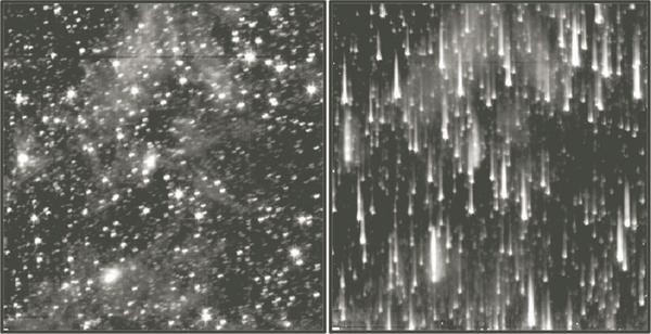
16 Low Resolution (R ~ 1000)
17 High Resolution (R ~ 50,000)
18 Spectral Dispersion Remember β is the outgoing angle of diffraction. At fixed spectrograph setup (i.e, for fixed spectograph tilt (α) and grating (d)), the spectral dispersion tells you how broadly dispersed the spectrum is: δβ/δλ Start with the grating equation: Differentiate with respect to λ: and solve for spectral dispersion: this is angular dispersion: units are radians/angstrom, for example
19 Simple Spectrograph slit grating camera lens collimator primary Notes: 1) For ease of sketching, this shows a transmissive system (refracting telescope, transmission grating). Most telescopes use a reflecting system. 2) the focal ratio of primary and collimator must be matched!
20 Linear Dispersion Coming off the grating, the light has to be refocused onto the detector via a camera lens. This maps the angular dispersion onto linear dispersion (Å/mm) on the detector. Remember imaging: the imaging plate scale was determined solely by the focal length of the telescope: S = 1/f L (in radians/mm). The same thing holds for the spectrograph camera: S cam = 1/f cam. Conversion via unit analysis: Linear dispersion (Å/mm) = plate scale (radians/mm) divided by spectral dispersion (radians/å) this is linear dispersion: units are Angstroms/mm, for example then given the physical pixel size you can turn that into Angstroms/pixel
21 Slitless Spectroscopy
22 Slitless Spectroscopy
23 The Spectrograph Slit The width of the slit determines the range of angles that get into the spectrograph. A wide slit allows a broader range of incoming angles, so it blurs the outgoing dispersed light and limits the spectral resolution. Characterizing slit width Physical size (linear): true size of slit, ω Projected width on the sky (angular): just like image size, it depends on the focal length of the telescope, ω θ = ω / f L (remember, if ω and f L are measured in the same units, this will come out in radians!) Projected width on the detector (linear): depends on the focal length of the camera and collimator lenses: ω = ω(f cam /f col ) also possibly a term due to anamorphic (de-)magnification (Schweizer 1979): r = dβ/dα = cos(α)/cos(β) Projected width on the detector (wavelength): use linear dispersion to convert microns to Angstroms: ω λ = ω d cos(β) / (m f cam ) Width in velocity (speed): use Doppler equation: ω v = ω λ (c/λ) Caution: always work through unit analysis when using the expressions to make sure you re using consistent units!

24 GoldCam Spectrograph (KPNO 2m)
 Spatial direction à Spectral")
25 Longslit Spectroscopy Point source (distant galaxy) Spatial direction à Spectral direction à
26 Longslit Spectroscopy Extended source (nearby galaxy)
27 Longslit Spectroscopy Extended source (nearby galaxy)

28 Longslit Spectroscopy Extended source (nearby galaxy)

29 Multi-object spectroscopy: Slitmasks

30 Multi-object spectroscopy: Slitmasks Metal plate with slits cut at the position of stars. Put at focal plane of telescope; star light passes through slit onto grating. Forms a series of spectra, one for each star. Spectra are offset in wavelength from each other, due to different X-positions of slits. Slits must not overlap in Y! (otherwise spectra will overlap)

31 Multi-object spectroscopy: Slitmasks

32 Multi-object spectroscopy: Fiber fed spectrographs Metal plate with holes cut at the position of stars. Put an optical fiber in each hole to carry the light down to the spectrograph. Produce many spectra, no constraints on fiber positions (other than they can t be too close spatially).
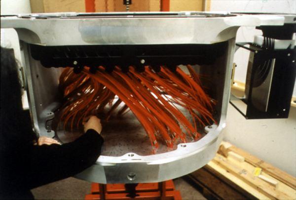
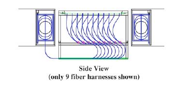
33 Multi-object spectroscopy: Fiber fed spectrographs

34 Multi-object spectroscopy: Integral Field Units (IFUs)

35 Multi-object spectroscopy: Integral Field Units (IFUs)
 Dithering to get full")
36 Multi-object spectroscopy: Integral Field Units (IFUs) Dithering to get full coverage
37 Spectroscopic Throughput
38 Spectroscopic Sky Subtraction
")
39 Spectroscopic Sky Subtraction M51 (B) M51 (Hα)

40 Spectroscopic Sky Subtraction WIYN/Sparsepak pointing

41 Spectroscopic Sky Subtraction
42 Spectroscopic Sky Subtraction
Spectrographs. C. A. Griffith, Class Notes, PTYS 521, 2016 Not for distribution.
 Spectrographs C A Griffith, Class Notes, PTYS 521, 2016 Not for distribution 1 Spectrographs and their characteristics A spectrograph is an instrument that disperses light into a frequency spectrum, which
Astronomical spectrographs. ASTR320 Wednesday February 20, 2019
 Astronomical spectrographs ASTR320 Wednesday February 20, 2019 Spectrographs A spectrograph is an instrument used to form a spectrum of an object Much higher spectral resolutions than possible with multiband
Control of Light. Emmett Ientilucci Digital Imaging and Remote Sensing Laboratory Chester F. Carlson Center for Imaging Science 8 May 2007
 Control of Light Emmett Ientilucci Digital Imaging and Remote Sensing Laboratory Chester F. Carlson Center for Imaging Science 8 May 007 Spectro-radiometry Spectral Considerations Chromatic dispersion
LECTURE 14 PHASORS & GRATINGS. Instructor: Kazumi Tolich
 LECTURE 14 PHASORS & GRATINGS Instructor: Kazumi Tolich Lecture 14 2 Reading chapter 33-5 & 33-8 Phasors n Addition of two harmonic waves n Interference pattern from multiple sources n Single slit diffraction
Diffraction. Introduction: Diffraction is bending of waves around an obstacle (barrier) or spreading of waves passing through a narrow slit.
 or spreading of waves passing through a narrow slit.") Introduction: Diffraction is bending of waves around an obstacle (barrier) or spreading of waves passing through a narrow slit. Diffraction amount depends on λ/a proportion If a >> λ diffraction is negligible
Introduction: Diffraction is bending of waves around an obstacle (barrier) or spreading of waves passing through a narrow slit. Diffraction amount depends on λ/a proportion If a >> λ diffraction is negligible
Spectrographs. Chapter The spectrograph
 Chapter 6 Spectrographs In this chapter, the basic principles of spectrograph design are reviewed. Both low order (low resolution) and high order (high resolution echelle configurations) are presented.
Chapter 36. Diffraction. Copyright 2014 John Wiley & Sons, Inc. All rights reserved.
 Chapter 36 Diffraction Copyright 36-1 Single-Slit Diffraction Learning Objectives 36.01 Describe the diffraction of light waves by a narrow opening and an edge, and also describe the resulting interference
Chapter 4 - Diffraction
 Diffraction is the phenomenon that occurs when a wave interacts with an obstacle. David J. Starling Penn State Hazleton PHYS 214 When a wave interacts with an obstacle, the waves spread out and interfere.
Optics Vac Work MT 2008
 Optics Vac Work MT 2008 1. Explain what is meant by the Fraunhofer condition for diffraction. [4] An aperture lies in the plane z = 0 and has amplitude transmission function T(y) independent of x. It is
Lecture 4 Recap of PHYS110-1 lecture Physical Optics - 4 lectures EM spectrum and colour Light sources Interference and diffraction Polarization
 Lecture 4 Recap of PHYS110-1 lecture Physical Optics - 4 lectures EM spectrum and colour Light sources Interference and diffraction Polarization Lens Aberrations - 3 lectures Spherical aberrations Coma,
Wave Optics. April 9, 2014 Chapter 34 1
 Wave Optics April 9, 2014 Chapter 34 1 Announcements! Remainder of this week: Wave Optics! Next week: Last of biweekly exams, then relativity! Last week: Review of entire course, no exam! Final exam Wednesday,
Electricity & Optics
 Physics 24100 Electricity & Optics Lecture 27 Chapter 33 sec. 7-8 Fall 2017 Semester Professor Koltick Clicker Question Bright light of wavelength 585 nm is incident perpendicularly on a soap film (n =
Chemistry Instrumental Analysis Lecture 6. Chem 4631
 Chemistry 4631 Instrumental Analysis Lecture 6 UV to IR Components of Optical Basic components of spectroscopic instruments: stable source of radiant energy transparent container to hold sample device
Spectrometers: Monochromators / Slits
 Spectrometers: Monochromators / Slits Monochromator Characteristics Dispersion: The separation, or wavelength selectivity, of a monochromator is dependent on its dispersion. Angular Dispersion: The change
Diffraction. Single-slit diffraction. Diffraction by a circular aperture. Chapter 38. In the forward direction, the intensity is maximal.
 Diffraction Chapter 38 Huygens construction may be used to find the wave observed on the downstream side of an aperture of any shape. Diffraction The interference pattern encodes the shape as a Fourier
College Physics 150. Chapter 25 Interference and Diffraction
 College Physics 50 Chapter 5 Interference and Diffraction Constructive and Destructive Interference The Michelson Interferometer Thin Films Young s Double Slit Experiment Gratings Diffraction Resolution
Lenses lens equation (for a thin lens) = (η η ) f r 1 r 2
 = (η η ) f r 1 r 2") Lenses lens equation (for a thin lens) 1 1 1 ---- = (η η ) ------ - ------ f r 1 r 2 Where object o f = focal length η = refractive index of lens material η = refractive index of adjacent material r 1
Lenses lens equation (for a thin lens) 1 1 1 ---- = (η η ) ------ - ------ f r 1 r 2 Where object o f = focal length η = refractive index of lens material η = refractive index of adjacent material r 1
Dr. Quantum. General Physics 2 Light as a Wave 1
 Dr. Quantum General Physics 2 Light as a Wave 1 The Nature of Light When studying geometric optics, we used a ray model to describe the behavior of light. A wave model of light is necessary to describe
Wave Optics. April 11, 2014 Chapter 34 1
 Wave Optics April 11, 2014 Chapter 34 1 Announcements! Exam tomorrow! We/Thu: Relativity! Last week: Review of entire course, no exam! Final exam Wednesday, April 30, 8-10 PM Location: WH B115 (Wells Hall)
Wave Phenomena Physics 15c. Lecture 19 Diffraction
 Wave Phenomena Physics 15c Lecture 19 Diffraction What We Did Last Time Studied interference > waves overlap Amplitudes add up Intensity = (amplitude) does not add up Thin-film interference Reflectivity
Michelson Interferometer
 Michelson Interferometer The Michelson interferometer uses the interference of two reflected waves The third, beamsplitting, mirror is partially reflecting ( half silvered, except it s a thin Aluminum
Models of Light The wave model: The ray model: The photon model:
 Models of Light The wave model: under many circumstances, light exhibits the same behavior as sound or water waves. The study of light as a wave is called wave optics. The ray model: The properties of
University Physics (Prof. David Flory) Chapt_37 Monday, August 06, 2007
 Chapt_37 Monday, August 06, 2007") Name: Date: 1. If we increase the wavelength of the light used to form a double-slit diffraction pattern: A) the width of the central diffraction peak increases and the number of bright fringes within
Name: Date: 1. If we increase the wavelength of the light used to form a double-slit diffraction pattern: A) the width of the central diffraction peak increases and the number of bright fringes within
Chapter 36. Diffraction. Dr. Armen Kocharian
 Chapter 36 Diffraction Dr. Armen Kocharian Diffraction Light of wavelength comparable to or larger than the width of a slit spreads out in all forward directions upon passing through the slit This phenomena
Chapter 5 Example and Supplementary Problems
 Chapter 5 Example and Supplementary Problems Single-Slit Diffraction: 1) A beam of monochromatic light (550 nm) is incident on a single slit. On a screen 3.0 meters away the distance from the central and
Diffraction Diffraction occurs when light waves pass through an aperture Huygen's Principal: each point on wavefront acts as source of another wave
 Diffraction Diffraction occurs when light waves pass through an aperture Huygen's Principal: each point on wavefront acts as source of another wave If light coming from infinity point source at infinity
(Fiber-optic Reosc Echelle Spectrograph of Catania Observatory)
") (Fiber-optic Reosc Echelle Spectrograph of Catania Observatory) The echelle spectrograph delivered by REOSC (France), was designed to work at the F/15 cassegrain focus of the 91-cm telescope. The spectrograph
(Fiber-optic Reosc Echelle Spectrograph of Catania Observatory) The echelle spectrograph delivered by REOSC (France), was designed to work at the F/15 cassegrain focus of the 91-cm telescope. The spectrograph
Physical Optics. You can observe a lot just by watching. Yogi Berra ( )
") Physical Optics You can observe a lot just by watching. Yogi Berra (1925-2015) OBJECTIVES To observe some interference and diffraction phenomena with visible light. THEORY In a previous experiment you
Physical Optics You can observe a lot just by watching. Yogi Berra (1925-2015) OBJECTIVES To observe some interference and diffraction phenomena with visible light. THEORY In a previous experiment you
Chapter 8: Physical Optics
 Chapter 8: Physical Optics Whether light is a particle or a wave had puzzled physicists for centuries. In this chapter, we only analyze light as a wave using basic optical concepts such as interference
Chapter 38. Diffraction Patterns and Polarization
 Chapter 38 Diffraction Patterns and Polarization Diffraction Light of wavelength comparable to or larger than the width of a slit spreads out in all forward directions upon passing through the slit This
The liquid s index of refraction is. v liquid = nm = = 460 nm 1.38
 HMWK 5 Ch 17: P 6, 11, 30, 31, 34, 42, 50, 56, 58, 60 Ch 18: P 7, 16, 22, 27, 28, 30, 51, 52, 59, 61 Ch. 17 P17.6. Prepare: The laser beam is an electromagnetic wave that travels with the speed of light.
specular diffuse reflection.
 Lesson 8 Light and Optics The Nature of Light Properties of Light: Reflection Refraction Interference Diffraction Polarization Dispersion and Prisms Total Internal Reflection Huygens s Principle The Nature
DIFFRACTION 4.1 DIFFRACTION Difference between Interference and Diffraction Classification Of Diffraction Phenomena
 4.1 DIFFRACTION Suppose a light wave incident on a slit AB of sufficient width b, as shown in Figure 1. According to concept of rectilinear propagation of light the region A B on the screen should be uniformly
Review Session 1. Dr. Flera Rizatdinova
 Review Session 1 Dr. Flera Rizatdinova Summary of Chapter 23 Index of refraction: Angle of reflection equals angle of incidence Plane mirror: image is virtual, upright, and the same size as the object
Final Exam and End Material Test Friday, May 12, 10:00-12:00
 Final Exam and End Material Test Friday, May 12, 10:00-12:00 Test rooms: Instructor Sections Room Dr. Hale F, H 104 Physics Dr. Kurter B, N 125 BCH Dr. Madison K, M B-10 Bertelsmeyer Dr. Parris J St. Pats
UNIT 102-9: INTERFERENCE AND DIFFRACTION
 Name St.No. - Date(YY/MM/DD) / / Section Group # UNIT 102-9: INTERFERENCE AND DIFFRACTION Patterns created by interference of light in a thin film. OBJECTIVES 1. Understand the creation of double-slit
To see how a sharp edge or an aperture affect light. To analyze single-slit diffraction and calculate the intensity of the light
 Diffraction Goals for lecture To see how a sharp edge or an aperture affect light To analyze single-slit diffraction and calculate the intensity of the light To investigate the effect on light of many
AP Physics Problems -- Waves and Light
 AP Physics Problems -- Waves and Light 1. 1975-4 (Physical Optics) a. Light of a single wavelength is incident on a single slit of width w. (w is a few wavelengths.) Sketch a graph of the intensity as
AP* Optics Free Response Questions
 AP* Optics Free Response Questions 1978 Q5 MIRRORS An object 6 centimeters high is placed 30 centimeters from a concave mirror of focal length 10 centimeters as shown above. (a) On the diagram above, locate
Chapter 36 Diffraction by C.-R. Hu
 Chapter 36 Diffraction by C.-R. Hu 1. Meaning of the term diffraction The term diffraction means that light does not simply travel in straight lines in a uniform medium, as the ray method seems to tell
Diffraction and Interference of Plane Light Waves
 PHY 92 Diffraction and Interference of Plane Light Waves Diffraction and Interference of Plane Light Waves Introduction In this experiment you will become familiar with diffraction patterns created when
Diffraction. Factors that affect Diffraction
 Diffraction What is one common property the four images share? Diffraction: Factors that affect Diffraction TELJR Publications 2017 1 Young s Experiment AIM: Does light have properties of a particle? Or
Chapter 24 - The Wave Nature of Light
 Chapter 24 - The Wave Nature of Light Summary Four Consequences of the Wave nature of Light: Diffraction Dispersion Interference Polarization Huygens principle: every point on a wavefront is a source of
25-1 Interference from Two Sources
 25-1 Interference from Two Sources In this chapter, our focus will be on the wave behavior of light, and on how two or more light waves interfere. However, the same concepts apply to sound waves, and other
Chapter 38 Wave Optics (II)
") Chapter 38 Wave Optics (II) Initiation: Young s ideas on light were daring and imaginative, but he did not provide rigorous mathematical theory and, more importantly, he is arrogant. Progress: Fresnel,
Chapter 38 Wave Optics (II) Initiation: Young s ideas on light were daring and imaginative, but he did not provide rigorous mathematical theory and, more importantly, he is arrogant. Progress: Fresnel,
Waves & Oscillations
 Physics 42200 Waves & Oscillations Lecture 41 Review Spring 2016 Semester Matthew Jones Final Exam Date:Tuesday, May 3 th Time:7:00 to 9:00 pm Room: Phys 112 You can bring one double-sided pages of notes/formulas.
Chapter 35 &36 Physical Optics
 Chapter 35 &36 Physical Optics Physical Optics Phase Difference & Coherence Thin Film Interference 2-Slit Interference Single Slit Interference Diffraction Patterns Diffraction Grating Diffraction & Resolution
Lecture 39. Chapter 37 Diffraction
 Lecture 39 Chapter 37 Diffraction Interference Review Combining waves from small number of coherent sources double-slit experiment with slit width much smaller than wavelength of the light Diffraction
UNIT VI OPTICS ALL THE POSSIBLE FORMULAE
 58 UNIT VI OPTICS ALL THE POSSIBLE FORMULAE Relation between focal length and radius of curvature of a mirror/lens, f = R/2 Mirror formula: Magnification produced by a mirror: m = - = - Snell s law: 1
Lab 7 Interference and diffraction
 Prep this lab, as usual. You may paste this entire lab into your notebook, including the data tables. All this should be completed prior to the start of lab on Wednesday, and I will score your completed
Physics 2c Lecture 25. Chapter 37 Interference & Diffraction
 Physics 2c Lecture 25 Chapter 37 Interference & Diffraction Outlook for rest of quarter Today: finish chapter 37 Tomorrow & Friday: E&M waves (Chapter 34) Next Monday, June 4 th : Quiz 8 on Chapter 37
Interference and Diffraction of Light
 Name Date Time to Complete h m Partner Course/ Section / Grade Interference and Diffraction of Light Reflection by mirrors and refraction by prisms and lenses can be analyzed using the simple ray model
NIRSpec Technical Note NTN / ESA-JWST-TN Author(s): G. Giardino Date of Issue: November 11, 2013 Version: 1.0
: G. Giardino Date of Issue: November 11, 2013 Version: 1.0") NIRSpec Technical Note NTN-013-011/ ESA-JWST-TN-093 Author(s): G. Giardino Date of Issue: November 11, 013 Version: 1.0 estec European Space Research and Technology Centre Keplerlaan 1 01 AZ Noordwijk
NIRSpec Technical Note NTN-013-011/ ESA-JWST-TN-093 Author(s): G. Giardino Date of Issue: November 11, 013 Version: 1.0 estec European Space Research and Technology Centre Keplerlaan 1 01 AZ Noordwijk
Diffraction: Propagation of wave based on Huygens s principle.
 Diffraction: In addition to interference, waves also exhibit another property diffraction, which is the bending of waves as they pass by some objects or through an aperture. The phenomenon of diffraction
Intermediate Physics PHYS102
 Intermediate Physics PHYS102 Dr Richard H. Cyburt Assistant Professor of Physics My office: 402c in the Science Building My phone: (304) 384-6006 My email: rcyburt@concord.edu My webpage: www.concord.edu/rcyburt
Matthew Schwartz Lecture 19: Diffraction and resolution
 Matthew Schwartz Lecture 19: Diffraction and resolution 1 Huygens principle Diffraction refers to what happens to a wave when it hits an obstacle. The key to understanding diffraction is a very simple
Diffraction. Light bends! Diffraction assumptions. Solution to Maxwell's Equations. The far-field. Fraunhofer Diffraction Some examples
 Diffraction Light bends! Diffraction assumptions Solution to Maxwell's Equations The far-field Fraunhofer Diffraction Some examples Diffraction Light does not always travel in a straight line. It tends
Diffraction Diffraction occurs when light waves is passed by an aperture/edge Huygen's Principal: each point on wavefront acts as source of another
 Diffraction Diffraction occurs when light waves is passed by an aperture/edge Huygen's Principal: each point on wavefront acts as source of another circular wave Consider light from point source at infinity
Interference. Electric fields from two different sources at a single location add together. The same is true for magnetic fields at a single location.
 Interference Electric fields from two different sources at a single location add together. The same is true for magnetic fields at a single location. Thus, interacting electromagnetic waves also add together.
Second Year Optics 2017 Problem Set 1
 Second Year Optics 2017 Problem Set 1 Q1 (Revision of first year material): Two long slits of negligible width, separated by a distance d are illuminated by monochromatic light of wavelength λ from a point
L 32 Light and Optics [3]
![L 32 Light and Optics [3]](/thumbs/78/77867745.jpg "L 32 Light and Optics [3]") L 32 Light and Optics [3] Measurements of the speed of light The bending of light refraction Total internal reflection Dispersion Dispersion Rainbows Atmospheric scattering Blue sky red sunsets Light and
L 32 Light and Optics [3] Measurements of the speed of light The bending of light refraction Total internal reflection Dispersion Dispersion Rainbows Atmospheric scattering Blue sky red sunsets Light and
Diffraction: Taking Light Apart
 Diffraction: Taking Light Apart Engage Student Guide A. Waves Let s first consider diffraction. It s part of everyday life, in which waves of energy don t seem to move in straight lines. Do the activity
Physics 272 Lecture 27 Interference (Ch ) Diffraction (Ch )
 Diffraction (Ch )") Physics 272 Lecture 27 Interference (Ch 35.4-5) Diffraction (Ch 36.1-3) Thin Film Interference 1 2 n 0 =1 (air) t n 1 (thin film) n 2 Get two waves by reflection off of two different interfaces. Ray 2
Physics 272 Lecture 27 Interference (Ch 35.4-5) Diffraction (Ch 36.1-3) Thin Film Interference 1 2 n 0 =1 (air) t n 1 (thin film) n 2 Get two waves by reflection off of two different interfaces. Ray 2
Waves & Oscillations
 Physics 42200 Waves & Oscillations Lecture 42 Review Spring 2013 Semester Matthew Jones Final Exam Date:Tuesday, April 30 th Time:1:00 to 3:00 pm Room: Phys 112 You can bring two double-sided pages of
PHYSICS 213 PRACTICE EXAM 3*
 PHYSICS 213 PRACTICE EXAM 3* *The actual exam will contain EIGHT multiple choice quiz-type questions covering concepts from lecture (16 points), ONE essay-type question covering an important fundamental
Design, implementation and characterization of a pulse stretcher to reduce the bandwith of a femtosecond laser pulse
 BACHELOR Design, implementation and characterization of a pulse stretcher to reduce the bandwith of a femtosecond laser pulse ten Haaf, G. Award date: 2011 Link to publication Disclaimer This document
2. THE PHYSICS OF DIFFRACTION GRATINGS
 Diffraction Grating Handbook - Chapter 1 2. THE PHYSICS OF DIFFRACTION GRATINGS PREVIOUS CHAPTER NEXT CHAPTER Copyright 2002, Thermo RGL, All Rights Reserved TABLE OF CONTENTS 2.1. THE GRATING EQUATION
2011 Optical Science & Engineering PhD Qualifying Examination Optical Sciences Track: Advanced Optics Time allowed: 90 minutes
 2011 Optical Science & Engineering PhD Qualifying Examination Optical Sciences Track: Advanced Optics Time allowed: 90 minutes Answer all four questions. All questions count equally. 3(a) A linearly polarized
Formulas of possible interest
 Name: PHYS 3410/6750: Modern Optics Final Exam Thursday 15 December 2011 Prof. Bolton No books, calculators, notes, etc. Formulas of possible interest I = ɛ 0 c E 2 T = 1 2 ɛ 0cE 2 0 E γ = hν γ n = c/v
Physics 202 Homework 9
 Physics 202 Homework 9 May 29, 2013 1. A sheet that is made of plastic (n = 1.60) covers one slit of a double slit 488 nm (see Figure 1). When the double slit is illuminated by monochromatic light (wavelength
PHYS 3410/3411/6750/6751: Modern Optics Midterm #2
 Name: PHYS 3410/3411/6750/6751: Modern Optics Midterm #2 Wednesday 17 November 2010 Prof. Bolton Only pen or pencil are allowed. No calculators or additional materials. PHYS 3410/3411/6750/6751 Midterm
Diffraction Efficiency
 Diffraction Efficiency Turan Erdogan Gratings are based on diffraction and interference: Diffraction gratings can be understood using the optical principles of diffraction and interference. When light
Introduction to Diffraction Gratings
 Introduction to Diffraction Diffraction (Ruled and Holographic) Diffraction gratings can be divided into two basic categories: holographic and ruled. A ruled grating is produced by physically forming grooves
Condenser Optics for Dark Field X-Ray Microscopy
 Condenser Optics for Dark Field X-Ray Microscopy S. J. Pfauntsch, A. G. Michette, C. J. Buckley Centre for X-Ray Science, Department of Physics, King s College London, Strand, London WC2R 2LS, UK Abstract.
The location of the bright fringes can be found using the following equation.
 What You Need to Know: In the past two labs we ve been thinking of light as a particle that reflects off of a surface or refracts into a medium. Now we are going to talk about light as a wave. If you take
Understanding Fraunhofer Diffraction
 [ Assignment View ] [ Eðlisfræði 2, vor 2007 36. Diffraction Assignment is due at 2:00am on Wednesday, January 17, 2007 Credit for problems submitted late will decrease to 0% after the deadline has passed.
10.2 Single-Slit Diffraction
 10. Single-Slit Diffraction If you shine a beam of light through a ide-enough opening, you might expect the beam to pass through ith very little diffraction. Hoever, hen light passes through a progressively
Chapter 36. Image Formation
 Chapter 36 Image Formation Apr 22, 2012 Light from distant things We learn about a distant thing from the light it generates or redirects. The lenses in our eyes create images of objects our brains can
PHYS 3410/6750: Modern Optics Midterm #2
 Name: PHYS 3410/6750: Modern Optics Midterm #2 Wednesday 16 November 2011 Prof. Bolton Only pen or pencil are allowed. No calculators or additional materials. PHYS 3410/6750 Fall 2011 Midterm #2 2 Problem
Basic optics. Geometrical optics and images Interference Diffraction Diffraction integral. we use simple models that say a lot! more rigorous approach
 Basic optics Geometrical optics and images Interference Diffraction Diffraction integral we use simple models that say a lot! more rigorous approach Basic optics Geometrical optics and images Interference
Unit 5.C Physical Optics Essential Fundamentals of Physical Optics
 Unit 5.C Physical Optics Essential Fundamentals of Physical Optics Early Booklet E.C.: + 1 Unit 5.C Hwk. Pts.: / 25 Unit 5.C Lab Pts.: / 20 Late, Incomplete, No Work, No Units Fees? Y / N 1. Light reflects
Downloaded from UNIT 06 Optics
 1 Mark UNIT 06 Optics Q1: A partially plane polarised beam of light is passed through a polaroid. Show graphically the variation of the transmitted light intensity with angle of rotation of the Polaroid.
Diffraction from small and large circular apertures
 Diffraction from small and large circular apertures Far-field intensity pattern from a small aperture Recall the Scale Theorem! This is the Uncertainty Principle for diffraction. Far-field intensity pattern
Lab 5: Diffraction and Interference
 Lab 5: Diffraction and Interference Light is a wave, an electromagnetic wave, and under the proper circumstances, it exhibits wave phenomena, such as constructive and destructive interference. The wavelength
Lecture 16 Diffraction Ch. 36
 Lecture 16 Diffraction Ch. 36 Topics Newtons Rings Diffraction and the wave theory Single slit diffraction Intensity of single slit diffraction Double slit diffraction Diffraction grating Dispersion and
1 Laboratory #4: Division-of-Wavefront Interference
 1051-455-0073, Physical Optics 1 Laboratory #4: Division-of-Wavefront Interference 1.1 Theory Recent labs on optical imaging systems have used the concept of light as a ray in goemetrical optics to model
PY212 Lecture 25. Prof. Tulika Bose 12/3/09. Interference and Diffraction. Fun Link: Diffraction with Ace Ventura
 PY212 Lecture 25 Interference and Diffraction Prof. Tulika Bose 12/3/09 Fun Link: Diffraction with Ace Ventura Summary from last time The wave theory of light is strengthened by the interference and diffraction
Physics 123 Optics Review
 Physics 123 Optics Review I. Definitions & Facts concave converging convex diverging real image virtual image real object virtual object upright inverted dispersion nearsighted, farsighted near point,
Lecture 6: Waves Review and Examples PLEASE REVIEW ON YOUR OWN. Lecture 6, p. 1
 Lecture 6: Waves Review and Examples PLEASE REVEW ON YOUR OWN Lecture 6, p. 1 Single-Slit Slit Diffraction (from L4) Slit of width a. Where are the minima? Use Huygens principle: treat each point across
EDUCATIONAL SPECTROPHOTOMETER ACCESSORY KIT AND EDUCATIONAL SPECTROPHOTOMETER SYSTEM
 GAIN 0 Instruction Manual and Experiment Guide for the PASCO scientific Model OS-8537 and OS-8539 02-06575A 3/98 EDUCATIONAL SPECTROPHOTOMETER ACCESSORY KIT AND EDUCATIONAL SPECTROPHOTOMETER SYSTEM CI-6604A
CHAPTER 9 TEST -- REVIEW
 IB PHYSICS Name: Period: Date: # Marks: 58 DEVIL PHYSICS BADDEST CLASS ON CAMPUS CHAPTER 9 TEST -- REVIEW 1. The graph elow shows how the displacement x of a particle undergoing simple harmonic motion
Single Slit Diffraction
 Name: Date: PC1142 Physics II Single Slit Diffraction 5 Laboratory Worksheet Part A: Qualitative Observation of Single Slit Diffraction Pattern L = a 2y 0.20 mm 0.02 mm Data Table 1 Question A-1: Describe
CHAPTER 26 INTERFERENCE AND DIFFRACTION
 CHAPTER 26 INTERFERENCE AND DIFFRACTION INTERFERENCE CONSTRUCTIVE DESTRUCTIVE YOUNG S EXPERIMENT THIN FILMS NEWTON S RINGS DIFFRACTION SINGLE SLIT MULTIPLE SLITS RESOLVING POWER 1 IN PHASE 180 0 OUT OF
Chapter 36 Diffraction
 Chapter 36 Diffraction In Chapter 35, we saw how light beams passing through different slits can interfere with each other and how a beam after passing through a single slit flares diffracts in Young's
Presented By:- Abhishek Chandra, Abhishek Singh, Akash Gupta, Abhishek Pandey, Amit Tiwari B.Sc.:-IIIrd Year
 Diffraction Grating Presented By:- Abhishek Chandra, Abhishek Singh, Akash Gupta, Abhishek Pandey, Amit Tiwari B.Sc.:-IIIrd Year DIFFRACTION The Phenomenon of bending of light round the corners of an obstacle
LECTURE 12 INTERFERENCE OF LIGHT. Instructor: Kazumi Tolich
 LECTURE 12 INTERFERENCE OF LIGHT Instructor: Kazumi Tolich Lecture 12 2 17.2 The interference of light Young s double-slit experiment Analyzing double-slit interference 17.3 The diffraction grating Spectroscopy
The image is virtual and erect. When a mirror is rotated through a certain angle, the reflected ray is rotated through twice this angle.
 1 Class XII: Physics Chapter 9: Ray optics and Optical Instruments Top Concepts 1. Laws of Reflection. The reflection at a plane surface always takes place in accordance with the following two laws: (i)
Tutorial Solutions. 10 Holographic Applications Holographic Zone-Plate
 10 Holographic Applications 10.1 Holographic Zone-Plate Tutorial Solutions Show that if the intensity pattern for on on-axis holographic lens is recorded in lithographic film, then a one-plate results.
E x Direction of Propagation. y B y
 x E x Direction of Propagation k z z y B y An electromagnetic wave is a travelling wave which has time varying electric and magnetic fields which are perpendicular to each other and the direction of propagation,
Optical/NIR Spectroscopy A3130. John Wilson Univ of Virginia
 Optical/NIR Spectroscopy A3130 John Wilson Univ of Virginia Topics: Photometry is low resolution spectroscopy Uses of spectroscopy in astronomy Data cubes and dimensionality challenge Spectrograph design