Design of a Precision Robot Wrist Interface. Patrick Willoughby Advisor: Alexander Slocum MIT Precision Engineering Research Group
|
|
|
- Kerry Chapman
- 6 years ago
- Views:
Transcription

1 Design of a Precision Robot Wrist Interface Patrick Willoughby Advisor: Alexander Slocum MIT Precision Engineering Research Group


2 Project Summary Problem: Current bolted robot wrist replacements are inaccurate, causing ~1.0 mm errors at robot tool which are transmitted to the work piece. Possible Solutions: 1. Costly and lengthy calibration procedures 2. Inexpensive classic ball and groove kinematic coupling 3. Very inexpensive three pin coupling 2
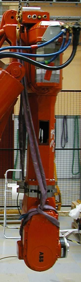
3 Application: ABB IRB 6400R Robot Heavy duty industrial robot Six degree of freedom manipulator Carrying capacity of 200 kg Maximum tool speed of 3 m/s Tool position repeatability of 0.1 mm Common applications Automotive assembly, welding, and painting Material Handling 3

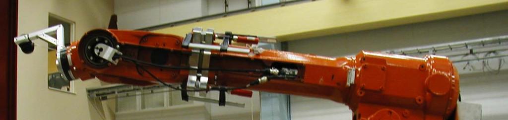
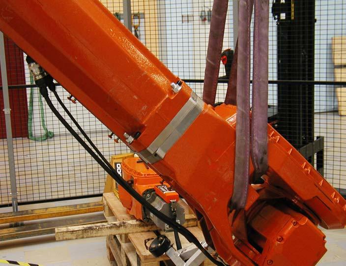
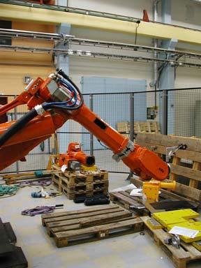
4 Current Wrist Replacement Requires ~½ hour to do replacement and 2 hours to perform recalibration of robot Wrist mass of ~100kg Replacement can cause severe damage to motor Concerns for worker safety Robot Wrist 4


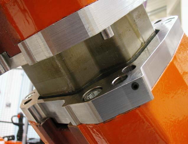
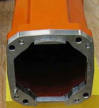
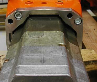
5 Existing Coupling Uses large surface contact with alignment pins and surfaces Repeatability is a function of machining tolerances Repeatability of 0.3 mm Stiffness derived from friction between interface surfaces Interface on Arm Interface on Wrist Friction Plate 5
6 Project Requirements and Strategy Improve repeatability of wrist replacement on IRB 6400R Minimize physical changes to existing wrist structure Minimize changes in structural performance of wrist Introduce concepts of exact constraint design and kinematic couplings to ABB Strategy: Develop kinematic coupling adapter plates that can be added to robot to test repeatability 6

7 Overview of Common Coupling Methods Pinned Joints Elastic Averaging Planar Kinematic Kinematic Couplings No Unique Position Non-Deterministic Non-Deterministic Kinematic Constraint 7
8 Exact Constraint or Kinematic Design Each component has an equal number of constrained points to number of degrees of freedom If component is over constrained, clearance and high tolerances required to prevent premature failure or assembly incompatibility Kinematic design means that the motion is exactly constrained and geometric equations can be written to describe its motion 8

9 Ball and Groove Coupling Design Uses standard kinematic coupling design of six point constraint in a stable coupling triangle Preload applied through ball centers to resist static loading 9
10 Coupling Stability Basic Definition A stable coupling is one which remains constrained when design loads are applied Many factors affect stability: Geometry Friction Preload Disturbance Loads 10

11 Hertz Contact Stress Design Exact constraint design creates contact at single points or lines, creating high contact stresses Managing Hertz contact stresses is the key to successful kinematic coupling design F F = 2 Contact Mechanics Equations: Equivalent radius and modulus R e = R 1 R major 1 minor + 1 R 2 major E e = E 1 E 2 Deflection of Contact Point 2 = 2 F 2 3 R e E e 1/3 + 1 R 2 minor Contact Pressure of Contact Ellipse q = 3F 2 cd c & d are diameters of ellipse 11


12 Canoe Ball and Groove Design Canoe Ball Design Places a section of a sphere with radius of 250 mm onto a small block to reduce contact stress Large shallow Hertzian stress zone Repeatability of ¼ micron or on the order of parts surface finish Stiffness and load capacity are 100 times that of a normal 1 ball Contact stresses determined to be 1/3 of allowable stress Fx Fy Fz Mx My Mz Normal Operation Emergency Stop Units in N or N-m 12
13 CAD Model for Ball and Groove Coupling Plates are 30mm thick Interface plates have negative features to couple with existing interface Interface plates installed between wrist and arm Tabs added to outside to hold large balls and grooves, coupling features in future can be integrated into wrist Grey Robot Structure Orange Arm Interface Plate Green Canoe Balls Blue Grooves Red Wrist Interface Plate Yellow Preload Bolts Not Shown Wrist Unit 13
14 CAD Model for Ball and Groove Coupling z z Uses separately machined canoe balls and grooves secured to plates Bolting Pattern z z Four bolts used to secure each plate to robot structure Four bolts to connect coupling Three separate preload bolts Expensive canoe features on permanent structure, cheaper grooves on disposable wrist Predicted laboratory repeatability in microns 14
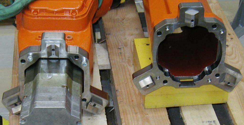
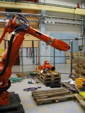
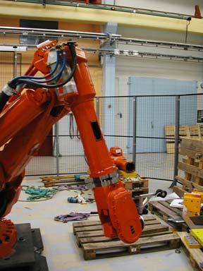
15 Prototypes for Ball and Groove Coupling 15

16 Planar Kinematic Coupling Design Uses a new type of coupling: Three Pin Coupling Constraint Pattern: Three Degrees of Freedom on Large Surface Contact Three Degrees of Freedom using Line Contacts on Pins In plane preload required to set coupling against friction Out of plane preload required to close interface and carry loads 16
17 Planar Kinematic Coupling Design Four step design process: 1. Determine interface geometry and method of preload. 2. Determine in plane preload to set coupling against interface friction using free body diagram of static load case. 3. Determine out of plane preload to maintain interface stiffness using free body diagram of disturbance load case. 4. Size pins to withstand contact and bending stresses with necessary safety factors. 17
18 CAD Model of Planar Kinematic Coupling Plates are ~20mm thick Interface plates have negative features to couple with existing interface Interface plates installed between wrist and arm Grey Upper Arm Red Arm Interface Plate with Pins for Coupling Blue Wrist Interface Plate with Receptacles Wrist Not Shown 18
19 CAD Model of Planar Kinematic Coupling All features are integral to the interface plates Bolting Pattern Four bolts used to secure each plate to robot structure Four bolts to connect coupling One in-plane preload bolt Changes to existing robot are minimal, replace control pin and add preload pin 19
20 Operation of Planar Kinematic Coupling Third Pin on Arm Plate Two Pins on Arm Plate Pill Shaped Hole for Pin in Wrist Plate Two Holes On Wrist Plate Preload Bolt - Steel bolt with brass tip 20
21 Prototypes for Planar Kinematic Coupling 21
 repeatability of canoe ball Test")

22 Prototype Wrist Plate Mounting Tests at ABB Robotics Västerås, Sweden July 2001: Tested existing coupling as well as the canoe ball and three pin wrist prototypes Test static and dynamic (5-point path) repeatability of canoe ball Test variety of preloads (canoe balls) Replacement in two orientations (45 and 90 degrees to ground) Measure tool point motion using Leica LTD500 Laser Tracker Repeatability of robot path + measurement system approximately 20 to 30 microns 22
23 Repeatability Performance of KC Repeatability (mm) Installation Angle Additional Preload Measurement Type Bolting 1 Original Interface 2 45º 0 Nm 5 pt Plain 3 45º 15 Nm 5 pt Plain 4 45º 50 Nm 5 pt Plain 5 45º 75 Nm 5 pt Plain 6 45º 120 Nm 5 pt Plain 7 90º 0 Nm 5 pt Refined 8 90º Clamps 5 pt Refined 9 90º Clamps Static Refined 23
24 Repeatability Performance of Three Pin Repeatability (mm) Damage!! Normal Wrist 2. 5 point measurement with 45º inclination 3. 5 point measurement with 90º inclination 4. 5 point measurement with 45º inclination Installation Issues: Preload could not be accurately applied as equipment was unavailable Damage occurred to alignment features caused by wrist twisting at interface during exchange 24


25 Positions of Robot for 5pt Measurement
26 Repeatability Results and Conclusions Performance of Different Coupling Designs Canoe balls vs. Normal 45 º = 35% reduction Canoe balls vs. Normal 90 º = 64% reduction Potential Three-pin vs. Normal 45 º = 44% reduction Performance of Different Installation Procedures for Canoe Ball Coupling Refined bolting procedure improved repeatability from mm to mm Mounting process at 90º improved repeatability from mm to mm Refined bolting procedure and mounting process at 90º improved repeatability from mm to mm 26
27 Project Conclusions Kinematic couplings can work in an industrial setting Classic ball and groove formation requires minor modifications for space restrictions and load capacity Three pin coupling requires further testing to verify results Industrial applications require more attention on actual installation procedure Some further work is required to develop a final product 27

28 Recommended Next Steps Adapt canoe ball design to fit into space of wrist Suggest production designs for different concepts Investigate: Three pin coupling in 90 degree position Effect of friction reduction using TiN coated elements or lubrication Coupling design independent of mounting position Applicability quasi-kinematic couplings Evaluate long-term dynamic performance 28
MEDIUM SCALE DESIGN CASE STUDY: WRIST INTERFACE. 4.1 Background and Problem Description
 Chapter 4 MEDIUM SCALE DESIGN CASE STUDY: WRIST INTERFACE 4.1 Background and Problem Description 4.1.1 Background Out of the entire line of ABB Robots, the IRB 6400R robot is one of the most versatile
High-Accuracy, Quick-Change, Robot Factory Interface
 High-Accuracy, Quick-Change, Robot Factory Interface John Hart (ajhart@mit.edu) Prof. Alexander Slocum, Advisor MIT Precision Engineering Research Group Project Goals Design, test, and demonstrate production
Prof. Alexander Slocum John Hart Pat Willoughby
 Kinematic Couplings and Elastic Averaging Precision, Intelligent, Low Cost Interfaces with Medical Applications? Prof. Alexander Slocum (slocum@mit.edu) John Hart (ajhart@mit.edu) Pat Willoughby (pjwst10@mit.edu)
Kinematic Coupling for Precision Fixturing & Assembly
 Kinematic Coupling for Precision Fixturing & Assembly Folkers E. Rojas, MS & Nevan C. Hanumara, PhD MIT 1 February 2013 material from Profs. Alexander H. Slocum & Martin Culpepper http://pergatory.mit.edu/
Chapter 2 DESIGN OF COUPLING INTERFACES. 2.1 General Coupling Description
 Chapter 2 DESIGN OF COUPLING INTERFACES 2.1 General Coupling Description In precision machine design, one of the most important steps in designing a machine is the consideration of the effect of interfaces
MACRO-SCALE PRECISION ALIGNMENT. 3.1 Precision Machine Design Alignment Principles
 Chapter 3 MACRO-SCALE PRECISION ALIGNMENT 3.1 Precision Machine Design Alignment Principles Whenever two solid bodies are positioned with respect to each other, the quality of the alignment can be described
Principles of Kinematic Constraint
 Principles of Kinematic Constraint For holding a body (rigid thing) with the highest precision, we require: Full 6 DoF constraint If 6 DoFs not fully constrained, then one is loose. No overconstraint Any
Kinematic Coupling Interchangeability for Modular Factory Equipment
 Kinematic Coupling Interchangeability for Modular Factory Equipment John Hart* Patrick Willoughby Prof. Alexander H. Slocum Precision Engineering Research Group Department of Mechanical Engineering Massachusetts
ADJUSTABLE GEOMETRIC CONSTRAINTS 2001 MIT PSDAM AND PERG LABS
 ADJUSTABLE GEOMETRIC CONSTRAINTS Why adjust kinematic couplings? KC Repeatability is orders of magnitude better than accuracy Accuracy = f ( manufacture and assemble ) Kinematic Coupling Accuracy Adjusted
Kinematic coupling interchangeability
 Precision Engineering 28 (2004) 1 15 Kinematic coupling interchangeability Anastasios John Hart, Alexander Slocum, Patrick Willoughby Precision Engineering Research Group, Department of Mechanical Engineering,
TRIBOMETERS MICRO-MACRO TRIBOLOGY TESTING
 TRIBOMETERS MICRO-MACRO TRIBOLOGY TESTING The Tribometer provides highly accurate and repeatable wear friction testing in rotative and linear modes compliant to ISO and ASTM standards. Designed, at the
Influence of geometric imperfections on tapered roller bearings life and performance
 Influence of geometric imperfections on tapered roller bearings life and performance Rodríguez R a, Calvo S a, Nadal I b and Santo Domingo S c a Computational Simulation Centre, Instituto Tecnológico de
Lesson: Lightweighting of Robot Gripper Arm
 Lesson: Lightweighting of Robot Gripper Arm This functionality is only available in Fusion 360 Ultimate. In this exercise we'll perform a Shape Optimization study to reduce the weight of a robot gripper
Application-Oriented Development of Parallel Kinematic Manipulators with Large Workspace
 Application-Oriented Development of Parallel Kinematic Manipulators with Large Workspace T. Brogårdh, S. Hanssen, ABB Automation Technologies, Robotics,Västerås, Sweden G. Hovland, The University of Queensland
Description. 2.8 Robot Motion. Floor-mounting. Dimensions apply to IRB 6400/ Shelf-mounting
 Description 2.8 Robot Motion Floor-mounting Dimensions apply to IRB 64/ 3.-7 2943 694 146 3 Shelf-mounting 67 94 2871 184 3116 Figure 8 Working space of IRB 64 and IRB 64S (dimensions in mm). Product Specification
CHAPTER 3 MODELLING, SIMULATION AND KINEMATIC STUDY OF 3 - DOF PARALLEL MANIPULATORS
 49 CHAPTER 3 MODELLING, SIMULATION AND KINEMATIC STUDY OF 3 - DOF PARALLEL MANIPULATORS 3.1 INTRODUCTION Most existing PKM can be classified into two main families. The PKM of the first family generally
Lesson 6: Assembly Structural Analysis
 Lesson 6: Assembly Structural Analysis In this lesson you will learn different approaches to analyze the assembly using assembly analysis connection properties between assembly components. In addition
2.76 / Lecture 5: Large/micro scale
 2.76 / 2.760 Lecture 5: Large/micro scale Constraints Micro-fabrication Micro-physics scaling Assignment Nano Micro Meso Macro Nano Nano Nano Micro Nano Meso Nano Macro Micro Nano Micro Micro Micro Meso
Application Notes for Team Hydrostatic Pad Bearings
 Application Notes for Team Hydrostatic Pad Bearings THESE COMMODITIES, TECHNOLOGY, OR SOFTWARE WERE EXPORTED FROM THE UNITED STATES IN ACCORDANCE WITH THE EXPORT ADMINISTRATION REGULATIONS. DIVERSION CONTRARY
Stiffness Analysis of the Tracker Support Bracket and Its Bolt Connections
 October 25, 2000 Stiffness Analysis of the Tracker Support Bracket and Its Bolt Connections Tommi Vanhala Helsinki Institute of Physics 1. INTRODUCTION...2 2. STIFFNESS ANALYSES...2 2.1 ENVELOPE...2 2.2
Cylinders in Vs An optomechanical methodology Yuming Shen Tutorial for Opti521 November, 2006
 Cylinders in Vs An optomechanical methodology Yuming Shen Tutorial for Opti521 November, 2006 Introduction For rotationally symmetric optical components, a convenient optomechanical approach which is usually
SUPPORTING LINEAR MOTION: A COMPLETE GUIDE TO IMPLEMENTING DYNAMIC LOAD SUPPORT FOR LINEAR MOTION SYSTEMS
 SUPPORTING LINEAR MOTION: A COMPLETE GUIDE TO IMPLEMENTING DYNAMIC LOAD SUPPORT FOR LINEAR MOTION SYSTEMS Released by: Keith Knight Catalyst Motion Group Engineering Team Members info@catalystmotiongroup.com
TOPOLOGICAL OPTIMIZATION OF STEERING KNUCKLE BY USING ADDITIVE MANUFACTURING PROCESS
 TOPOLOGICAL OPTIMIZATION OF STEERING KNUCKLE BY USING ADDITIVE MANUFACTURING PROCESS Prof.P.S.Gorane 1,Mr. Piyush Jain 2 Mechanical engineering, G. S.Mozecollege of engineering, Savitri Bai Phule Pune
High Torque Type Ball Spline
 58-1E Models LBS, LBST, LBF, LBR and LBH Seal Spline shaft Spline nut Ball Retainer Snap ring Fig.1 Structure of Model LBS Point of Selection Point of Design Options Precautions on Use Accessories for
Manipulator Path Control : Path Planning, Dynamic Trajectory and Control Analysis
 Manipulator Path Control : Path Planning, Dynamic Trajectory and Control Analysis Motion planning for industrial manipulators is a challenging task when obstacles are present in the workspace so that collision-free
Synopsis of Risley Prism Beam Pointer
 Synopsis of Risley Prism Beam Pointer Mark T. Sullivan Lockheed Martin Space Systems Advanced Technology Center, 3251 Hanover Street, Palo Alto, CA 94304 mark.t.sullivan@lmco.com 650/424-2722 SUMMARY This
IMECE FUNCTIONAL INTERFACE-BASED ASSEMBLY MODELING
 Proceedings of IMECE2005 2005 ASME International Mechanical Engineering Congress and Exposition November 5-11, 2005, Orlando, Florida USA IMECE2005-79945 FUNCTIONAL INTERFACE-BASED ASSEMBLY MODELING James
Optimizing the Utility Scale Solar Megahelion Drive End-Cap (Imperial Units)
") Autodesk Inventor Tutorial Exercise Optimizing the Utility Scale Solar Megahelion Drive End-Cap www.autodesk.com/sustainabilityworkshop Contents OPTIMIZING THE USS SOLAR TRACKING END CAP... 3 OBJECTIVE...
Autodesk Inventor Tutorial Exercise Optimizing the Utility Scale Solar Megahelion Drive End-Cap www.autodesk.com/sustainabilityworkshop Contents OPTIMIZING THE USS SOLAR TRACKING END CAP... 3 OBJECTIVE...
Lesson 1: Introduction to Pro/MECHANICA Motion
 Lesson 1: Introduction to Pro/MECHANICA Motion 1.1 Overview of the Lesson The purpose of this lesson is to provide you with a brief overview of Pro/MECHANICA Motion, also called Motion in this book. Motion
Design and Analysis for a Large Two-Lens Cell Mount Katie Schwertz OptoMechanics 523: Final Project May 15, 2009
 Design and Analysis for a Large Two-Lens Cell Mount Katie Schwertz OptoMechanics 523: Final Project May 5, 2009 Abstract Presented below is a cell mount for two lenses that are 6 in diameter and made of
Lift Up Floor Locks Multi-Directional Castor. W Series. M Series (full stainless steel) WHEELS & CASTORS
 WHEELS & CASTORS") Lift Up Floor s Multi-Directional Castor K Series M Series O Series M Series (full stainless steel) W Series WHEELS & CASTORS WWW.SITECRAFT.COM.AU WHEELS & CASTORS Lift Up Floor s Used on warehouse trolleys,
Lift Up Floor s Multi-Directional Castor K Series M Series O Series M Series (full stainless steel) W Series WHEELS & CASTORS WWW.SITECRAFT.COM.AU WHEELS & CASTORS Lift Up Floor s Used on warehouse trolleys,
Kinematic Design Principles
 Kinematic Design Principles BJ Furman 24SEP97 Introduction Machines and instruments are made up of elements that are suitably arranged and many of which that are movably connected. Two parts that are in
Tutorial 1: Welded Frame - Problem Description
 Tutorial 1: Welded Frame - Problem Description Introduction In this first tutorial, we will analyse a simple frame: firstly as a welded frame, and secondly as a pin jointed truss. In each case, we will
NUMERICAL ANALYSIS OF ROLLER BEARING
 Applied Computer Science, vol. 12, no. 1, pp. 5 16 Submitted: 2016-02-09 Revised: 2016-03-03 Accepted: 2016-03-11 tapered roller bearing, dynamic simulation, axial load force Róbert KOHÁR *, Frantisek
KR QUANTEC K ultra. Robots. With F Variants Specification. KUKA Roboter GmbH. Issued: Version: Spez KR QUANTEC K ultra V10 KR QUANTEC
 Robots KUKA Roboter GmbH KR QUANTEC K ultra With F Variants Specification KR QUANTEC K ultra Issued: 02.09.2016 Version: Spez KR QUANTEC K ultra V10 Copyright 2016 KUKA Roboter GmbH Zugspitzstraße 140
Non-Linear Analysis of Bolted Flush End-Plate Steel Beam-to-Column Connection Nur Ashikin Latip, Redzuan Abdulla
 Non-Linear Analysis of Bolted Flush End-Plate Steel Beam-to-Column Connection Nur Ashikin Latip, Redzuan Abdulla 1 Faculty of Civil Engineering, Universiti Teknologi Malaysia, Malaysia redzuan@utm.my Keywords:
LightHinge+: Additively manufactured lightweight hood hinge with integrated pedestrian protection
 LightHinge+: Additively manufactured lightweight hood hinge with integrated pedestrian protection Sebastian Flügel EDAG Engineering GmbH HANNOVER MESSE 26.04.2018 EDAG Engineering GmbH: Portfolio Folie
Design and Development of Cartesian Robot for Machining with Error Compensation and Chatter Reduction
 International Journal of Engineering Research and Technology. ISSN 0974-3154 Volume 6, Number 4 (2013), pp. 449-454 International Research Publication House http://www.irphouse.com Design and Development
Computer Life (CPL) ISSN: Finite Element Analysis of Bearing Box on SolidWorks
 ISSN: Finite Element Analysis of Bearing Box on SolidWorks") Computer Life (CPL) ISSN: 1819-4818 Delivering Quality Science to the World Finite Element Analysis of Bearing Box on SolidWorks Chenling Zheng 1, a, Hang Li 1, b and Jianyong Li 1, c 1 Shandong University
Computer Life (CPL) ISSN: 1819-4818 Delivering Quality Science to the World Finite Element Analysis of Bearing Box on SolidWorks Chenling Zheng 1, a, Hang Li 1, b and Jianyong Li 1, c 1 Shandong University
Development of Backhoe Machine By 3-D Modelling using CAD Software and Verify the Structural Design By using Finite Element Method
 IJIRST International Journal for Innovative Research in Science & Technology Volume 2 Issue 1 June 2015 ISSN (online): 2349-6010 Development of Backhoe Machine By 3-D Modelling using CAD Software and Verify
Robots. KUKA Roboter GmbH KR 360 FORTEC. With F and C Variants Specification. Issued: Version: Spez KR 360 FORTEC V2
 Robots KUKA Roboter GmbH KR 360 FORTEC With F and C Variants Specification Issued: 16.04.2014 Version: Spez KR 360 FORTEC V2 Copyright 2014 KUKA Laboratories GmbH Zugspitzstraße 140 D-86165 Augsburg Germany
ENGINEERING MEASUREMENTS ENTERPRISE LTD. TECHNICAL REPORT RESULTS OF DEVIATION MEASUREMENTS AND GEOMETRY OF ROTARY KILN GEOCEMENT PLANT
 GEOSERVEX s.c. Zbigniew i Boleslaw Krystowczyk e-mail: office@geoservex.com.pl http://www.geoservex.com.pl office: ul. Kościuszki /19A 8-9 Bydgoszcz, POLAND tel: (+48) 34 6 fax: (+48) 34 6 EU VAT ID No:
Design of a Parallel Mechanism with Large Joint Clearances for Precise Motion
 Design of a Parallel Mechanism with Large Joint Clearances for Precise Motion Brandon DeMars, Doug Esper, Beth Kovacic, Sarah Richter ME 450, Fall 2009, Project #17 Section Intructor: Professor Yoram Koren
Enhanced Performance of a Slider Mechanism Through Improved Design Using ADAMS
 Enhanced Performance of a Slider Mechanism Through Improved Design Using ADAMS (Nazeer Shareef, Sr. R&D Engr., BAYER CORP., Elkhart, IN) Introduction Understanding of the influence of critical parameters
TOPOLOGICAL, SIZE AND SHAPE OPTIMIZATION OF AN UNDERWING PYLON SPIGOT
 TOPOLOGICAL, SIZE AND SHAPE OPTIMIZATION OF AN UNDERWING PYLON SPIGOT Prepared by: M. Basaglia (Alenia Aermacchi), S. Boni Cerri (Alenia Aermacchi), G. Turinetti (Altair) Topological, Size and Shape Optimization
2: Static analysis of a plate
 2: Static analysis of a plate Topics covered Project description Using SolidWorks Simulation interface Linear static analysis with solid elements Finding reaction forces Controlling discretization errors
Roller Rail Systems. (Additional roller runner blocks SNS R1822, SLS R1823, FXS R1854) R310EN 2315 ( ) The Drive & Control Company
 R310EN 2315 ( ) The Drive & Control Company") Roller Rail Systems (Additional roller runner blocks SNS R18, SLS R183, FXS R1854) R31EN 315 (1.9) The Drive & Control Company Bosch Rexroth AG Linear Motion and Assembly Technologies Ball Rail Systems
Roller Rail Systems (Additional roller runner blocks SNS R18, SLS R183, FXS R1854) R31EN 315 (1.9) The Drive & Control Company Bosch Rexroth AG Linear Motion and Assembly Technologies Ball Rail Systems
GrafiCalc Examples. Here are nineteen (19) examples that illustrate proven applications of GrafiCalc technology.
 examples that illustrate proven applications of GrafiCalc technology.") GrafiCalc Examples Here are nineteen (19) examples that illustrate proven applications of GrafiCalc technology. The examples have been arranged to show the following capabilities. 1. Predictive engineering
GrafiCalc Examples Here are nineteen (19) examples that illustrate proven applications of GrafiCalc technology. The examples have been arranged to show the following capabilities. 1. Predictive engineering
Design and Validation of XY Flexure Mechanism
 Design and Validation of XY Flexure Mechanism 1 Pratik M. Waghmare, 2 Shrishail B. Sollapur 1 Research Scholar, 2 Assistant Professor 1,2 Department of Mechanical Engineering, 1.2 Sinhgad Academy of Engineering,
1. Introduction 1 2. Mathematical Representation of Robots
 1. Introduction 1 1.1 Introduction 1 1.2 Brief History 1 1.3 Types of Robots 7 1.4 Technology of Robots 9 1.5 Basic Principles in Robotics 12 1.6 Notation 15 1.7 Symbolic Computation and Numerical Analysis
Tube stamping simulation for the crossmember of rear suspension system
 Tube stamping simulation for the crossmember of rear suspension system G. Borgna A. Santini P. Monchiero Magneti Marelli Suspension Systems Abstract: A recent innovation project at Magneti Marelli Suspension
Introduction to ANSYS Mechanical
 Lecture 6 Modeling Connections 15.0 Release Introduction to ANSYS Mechanical 1 2012 ANSYS, Inc. February 12, 2014 Chapter Overview In this chapter, we will extend the discussion of contact control begun
CLAMPS & SUPPORTS CATALOG
 ISO-900:2008 CLAMPS & SUPPORTS CATALOG Phone: 28 96 0900 Fax: 28 96 000 Email: sales@expotechusa.com Web: expotechusa.com 32 Cat. No. Page Cat. No. Page Cat. No. Page 07667... 6 03936... 2 038292... 0
Ambar Mitra. Concept Map Manual
 Ambar Mitra Concept Map Manual Purpose: This manual contains the instructions for using the Concept Map software. We will show the features by solving three problems: (i) rosette and maximum, shear strain
Mechanical simulation design of the shaft type hybrid mechanical arm based on Solidworks
 International Forum on Energy, Environment and Sustainable Development (IFEESD 2016) Mechanical simulation design of the shaft type hybrid mechanical arm based on Solidworks Liu Yande1, a Hu Jun2,b Ouyang
Guangxi University, Nanning , China *Corresponding author
 2017 2nd International Conference on Applied Mechanics and Mechatronics Engineering (AMME 2017) ISBN: 978-1-60595-521-6 Topological Optimization of Gantry Milling Machine Based on Finite Element Method
Lecture 5 Modeling Connections
 Lecture 5 Modeling Connections 16.0 Release Introduction to ANSYS Mechanical 1 2015 ANSYS, Inc. February 27, 2015 Chapter Overview In this chapter, we will extend the discussion of contact control begun
CODE Product Solutions
 CODE Product Solutions Simulation Innovations Glass Fiber Reinforced Structural Components for a Group 1 Child Harold van Aken About Code Product Solutions Engineering service provider Specialised in Multiphysics
Design of integrated eccentric mechanisms and exact constraint fixtures for micron-level repeatability and accuracy
 Precision Engineering 29 (2005) 65 80 Design of integrated eccentric mechanisms and exact constraint fixtures for micron-level repeatability and accuracy Martin L. Culpepper, Mangudi Varadarajan Kartik,
Analysis of Detroit Seismic Joint System
 Analysis of Detroit Seismic Joint System for EMSEAL Corporation Prepared by Haig Saadetian, P.Eng. Senior Consultant ROI Engineering Inc. 50 Ronson Drive, Suite 120 Toronto ON M9W 1B3 26-April-2009 1 Contents
Titanium Topology Optimized TiTO 3D Printed Satellite Panel Support System
 Titanium Topology Optimized TiTO 3D Printed Satellite Panel Support System White Paper By Precision ADM Abstract Precision ADM developed a TiTO (Titanium Topology Optimized) Aerospace Panel Support Structure.
Kinematics of the Stewart Platform (Reality Check 1: page 67)
") MATH 5: Computer Project # - Due on September 7, Kinematics of the Stewart Platform (Reality Check : page 7) A Stewart platform consists of six variable length struts, or prismatic joints, supporting a
MATH 5: Computer Project # - Due on September 7, Kinematics of the Stewart Platform (Reality Check : page 7) A Stewart platform consists of six variable length struts, or prismatic joints, supporting a
Tool Changers and Collision Protection Automatic changers for robot and manual handling systems Integrated connections for media and power supply
 The Modular Gripper System Offers Perfect solutions for press automation and robot handling Standard components for designing complex gripper systems 4 octagonal profile sizes for weight optimized design
ASU Series. XY Dual Guide Stage. Direct drive, zero cogging, zero backlash linear motor. Linear encoder options of 1μm, 0.5μm, and 0.
 ASU Series XY Dual Guide Stage Direct drive, zero cogging, zero backlash linear motor Linear encoder options of 1μm, 0.5μm, and 0.1μm High accelerations (up to 10m/s 2 ) and speeds (up to 5m/s) Smooth
Technical Report Example (1) Chartered (CEng) Membership
 Chartered (CEng) Membership") Technical Report Example (1) Chartered (CEng) Membership A TECHNICAL REPORT IN SUPPORT OF APPLICATION FOR CHARTERED MEMBERSHIP OF IGEM DESIGN OF 600 (103 BAR) 820MM SELF SEALING REPAIR CLAMP AND VERIFICATION
Technical Report Example (1) Chartered (CEng) Membership A TECHNICAL REPORT IN SUPPORT OF APPLICATION FOR CHARTERED MEMBERSHIP OF IGEM DESIGN OF 600 (103 BAR) 820MM SELF SEALING REPAIR CLAMP AND VERIFICATION
TABLE OF CONTENTS SECTION 2 BACKGROUND AND LITERATURE REVIEW... 3 SECTION 3 WAVE REFLECTION AND TRANSMISSION IN RODS Introduction...
 TABLE OF CONTENTS SECTION 1 INTRODUCTION... 1 1.1 Introduction... 1 1.2 Objectives... 1 1.3 Report organization... 2 SECTION 2 BACKGROUND AND LITERATURE REVIEW... 3 2.1 Introduction... 3 2.2 Wave propagation
A Strain Free Lock and Release Mechanism for an Elastically Suspended Two-Axis Gimbal
 A Strain Free Lock and Release Mechanism for an Elastically Suspended Two-Axis Gimbal Armond Asadurian Moog Inc., Chatsworth Operations, 21339 Nordhoff Street, Chatsworth, CA 91311 Tel: 001-818-341-5156
Rebecca R. Romatoski. B.S. Mechanical Engineering Massachusetts Institute of Technology, 2006
 Robotic End Effecter for the Introduction to Robotics Laboratory Robotic Arms by Rebecca R. Romatoski B.S. Mechanical Engineering Massachusetts Institute of Technology, 2006 SUBMITTED TO THE DEPARTMENT
Optimal Support Solution for a Meniscus Mirror Blank
 Preliminary Design Review Optimal Support Solution for a Meniscus Mirror Blank Opti 523 Independent Project Edgar Madril Scope For this problem an optimal solution for a mirror support is to be found for
Tool Center Position Determination of Deformable Sliding Star by Redundant Measurement
 Applied and Computational Mechanics 3 (2009) 233 240 Tool Center Position Determination of Deformable Sliding Star by Redundant Measurement T. Vampola a, M. Valášek a, Z. Šika a, a Faculty of Mechanical
Module 1 : Introduction to robotics. Lecture 3 : Industrial Manipulators & AGVs. Objectives. History of robots : Main bodies and wrists
 Module 1 : Introduction to robotics Lecture 3 : Industrial Manipulators & AGVs Objectives In this course you will learn the following History of development of robots. Main body types of manipulators with
10/25/2018. Robotics and automation. Dr. Ibrahim Al-Naimi. Chapter two. Introduction To Robot Manipulators
 Robotics and automation Dr. Ibrahim Al-Naimi Chapter two Introduction To Robot Manipulators 1 Robotic Industrial Manipulators A robot manipulator is an electronically controlled mechanism, consisting of
CHAPTER 8 FINITE ELEMENT ANALYSIS
 If you have any questions about this tutorial, feel free to contact Wenjin Tao (w.tao@mst.edu). CHAPTER 8 FINITE ELEMENT ANALYSIS Finite Element Analysis (FEA) is a practical application of the Finite
Introduction To Robotics (Kinematics, Dynamics, and Design)
") Introduction To Robotics (Kinematics, Dynamics, and Design) SESSION # 5: Concepts & Defenitions Ali Meghdari, Professor School of Mechanical Engineering Sharif University of Technology Tehran, IRAN 11365-9567
Introduction To Robotics (Kinematics, Dynamics, and Design) SESSION # 5: Concepts & Defenitions Ali Meghdari, Professor School of Mechanical Engineering Sharif University of Technology Tehran, IRAN 11365-9567
Mechanical Design Challenges for Collaborative Robots
 Motor Technologies Mechanical Design Challenges for Collaborative Robots TN-3301 REV 170526 THE CHALLENGE Robotics and additive manufacturing markets have entered into a new phase of growth. This growth
Modelling Flat Spring Performance Using FEA
 Modelling Flat Spring Performance Using FEA Blessing O Fatola, Patrick Keogh and Ben Hicks Department of Mechanical Engineering, University of Corresponding author bf223@bath.ac.uk Abstract. This paper
Micro coordinate measuring machine for parallel measurement of microstructures
 Micro coordinate measuring machine for parallel measurement of microstructures Christian Schrader 1*, Christian Herbst 1, Rainer Tutsch 1, Stephanus Büttgenbach 2, Thomas Krah 2 1 TU Braunschweig, Institute
High bandwidth fast steering mirror
 High bandwidth fast steering mirror Presenter Francisc M. Tapos Authors:Francisc M. Tapos a, Derek J. Edinger a, Timothy R. Hilby a, Melvin S. Ni a, Buck C. Holmes b, David M. Stubbs a a Lockheed Martin
MSR Team SAVI. Satellite Active Vibration Inverter
 MSR Team SAVI Satellite Active Vibration Inverter Wasseem Bel Patrick Byrne Blake Firner Corey Hyatt Joseph Schmitz Justin Tomasetti Jackson Vlay Benjamin Zatz Project Purpose Cryocoolers create Exported
Using Algebraic Geometry to Study the Motions of a Robotic Arm
 Using Algebraic Geometry to Study the Motions of a Robotic Arm Addison T. Grant January 28, 206 Abstract In this study we summarize selected sections of David Cox, John Little, and Donal O Shea s Ideals,
Design of three-dimensional photoelectric stylus micro-displacement measuring system
 Available online at www.sciencedirect.com Procedia Engineering 15 (011 ) 400 404 Design of three-dimensional photoelectric stylus micro-displacement measuring system Yu Huan-huan, Zhang Hong-wei *, Liu
AMP Drawer Series Connectors Miniature Power Drawer (MPD) Connectors
 Connectors") Miniature Power Drawer (MPD) Connectors Product Facts High mating cycle life Low Mating and Un-mating force (< 0.2lbs per contact) Single-piece molded housing Molded-in guide pins provide generous blind-mateability
Miniature Power Drawer (MPD) Connectors Product Facts High mating cycle life Low Mating and Un-mating force (< 0.2lbs per contact) Single-piece molded housing Molded-in guide pins provide generous blind-mateability
FUNCTIONAL OPTIMIZATION OF WINDSHIELD WIPER MECHANISMS IN MBS (MULTI-BODY SYSTEM) CONCEPT
 CONCEPT") FUNCTIONAL OPTIMIZATION OF WINDSHIELD WIPER MECHANISMS IN MBS (MULTI-BODY SYSTEM) CONCEPT Cătălin ALEXANDRU 1 Abstract: In this paper, the functional optimization of windshield wiper mechanisms is performed,
FUNCTIONAL OPTIMIZATION OF WINDSHIELD WIPER MECHANISMS IN MBS (MULTI-BODY SYSTEM) CONCEPT Cătălin ALEXANDRU 1 Abstract: In this paper, the functional optimization of windshield wiper mechanisms is performed,
Shell-to-Solid Element Connector(RSSCON)
") WORKSHOP 11 Shell-to-Solid Element Connector(RSSCON) Solid Shell MSC.Nastran 105 Exercise Workbook 11-1 11-2 MSC.Nastran 105 Exercise Workbook WORKSHOP 11 Shell-to-Solid Element Connector The introduction
WORKSHOP 11 Shell-to-Solid Element Connector(RSSCON) Solid Shell MSC.Nastran 105 Exercise Workbook 11-1 11-2 MSC.Nastran 105 Exercise Workbook WORKSHOP 11 Shell-to-Solid Element Connector The introduction
Modeling Strategies for Dynamic Finite Element Cask Analyses
 Session A Package Analysis: Structural Analysis - Modeling Modeling Strategies for Dynamic Finite Element Cask Analyses Uwe Zencker, Günter Wieser, Linan Qiao, Christian Protz BAM Federal Institute for
Separation Connector. Analysis of Final Design Concepts Document
 Separation Connector By Koll Christianson, Amelia Fuller, Luis Herrera, Zheng Lian, and Shaun Shultz Team 19 Analysis of Final Design Concepts Document Submitted towards partial fulfillment of the requirements
Top Layer Subframe and Node Analysis
 Top Layer Subframe and Node Analysis By Paul Rasmussen 2 August, 2012 Introduction The top layer of the CCAT backing structure forms a critical interface between the truss and the primary subframes. Ideally
LINEAR TABLES
 LINEAR TABLES LINEAR TABLES NIASA'S LINEAR TABLES are translating units that can be easily controlled manually or commanded by CNC. Due to their lightness and ease of application they are very useful elements
6-Axis Force and Torque in All Six Axes 50N/1Nm to 50kN/5kNm Capacities Compact Size. Specifications
 6A _V1.3 2016_07_25 The Leader in Force Measurement Model 6A Series 6 Axis Load Cells (Fx Fy Fz Mx My Mz) 6-Axis Force and Torque in All Six Axes 50N/1Nm to 50kN/5kNm Capacities Compact Size Low Crosstalk
Inverse Kinematics. Given a desired position (p) & orientation (R) of the end-effector
 & orientation (R) of the end-effector") Inverse Kinematics Given a desired position (p) & orientation (R) of the end-effector q ( q, q, q ) 1 2 n Find the joint variables which can bring the robot the desired configuration z y x 1 The Inverse
Inverse Kinematics Given a desired position (p) & orientation (R) of the end-effector q ( q, q, q ) 1 2 n Find the joint variables which can bring the robot the desired configuration z y x 1 The Inverse
CONTOUR-CRAFTING-CARTESIAN-CABLE ROBOT SYSTEM CONCEPTS: WORKSPACE AND STIFFNESS COMPARISONS
 IDETC/CIE 2008 ASME 2008 International Design Engineering Technical Conferences and Computers and Information in Engineering Conference August 3-6, 2008, New York, NY, USA DETC2008-49478 CONTOUR-CRAFTING-CARTESIAN-CABLE
Purdue e-pubs. Purdue University. Jeongil Park Samsung Electronics Co. Nasir Bilal Purdue University. Douglas E. Adams Purdue University
 Purdue University Purdue e-pubs International Compressor Engineering Conference School of Mechanical Engineering 26 Development of a Two-Dimensional Finite Element Model of a Suction Valve for Reduction
Chapter 1 Introduction
 Chapter 1 Introduction Generally all considerations in the force analysis of mechanisms, whether static or dynamic, the links are assumed to be rigid. The complexity of the mathematical analysis of mechanisms
Oct 16 Rev D
 Next Generation ARINC 600 Connector Application Specification 114-13272 05 Oct 16 Rev D NOTE All numerical values are in metric units [with U.S. customary units in brackets]. Dimensions are in millimeters
THE FACTORY AUTOMATION COMPANY. Force Sensor. Tactile intelligence. Assembling Contouring Measuring
 THE FACTORY AUTOMATION COMPANY Force Sensor Tactile intelligence WWW.FANUC.EU Assembling Contouring Measuring Automated craftsmanship for assembly, contouring and measuring applications FANUC s range of
WEEKS 1-2 MECHANISMS
 References WEEKS 1-2 MECHANISMS (METU, Department of Mechanical Engineering) Text Book: Mechanisms Web Page: http://www.me.metu.edu.tr/people/eres/me301/in dex.ht Analitik Çözümlü Örneklerle Mekanizma
Abstract. Introduction:
 Abstract This project analyzed a lifecycle test fixture for stress under generic test loading. The maximum stress is expected to occur near the shrink fit pin on the lever arm. The model was constructed
INTERNSHIP REPORT Analysis of a generic lifting table Ruben Teunis s Mechanical Engineering Applied Mechanics, CTW
 INTERNSHIP REPORT Analysis of a generic lifting table Ruben Teunis s1112392 Mechanical Engineering Applied Mechanics, CTW 25-08-2014 5-12-2014 Enschede, The Netherlands Supervisor: T. Tinga Hengelo, The
A-dec 586 Ceiling Monitor Mount
 Installation Guide A-dec 586 Ceiling Monitor Mount Recommended Tools 7/16" wrench Socket set and ratchet with 6" extension Phillips head and standard screwdrivers Diagonal cutters Level 3/8" drill with
[1] involuteσ(spur and Helical Gear Design)
![[1] involuteσ(spur and Helical Gear Design)](/thumbs/82/86018000.jpg "[1] involuteσ(spur and Helical Gear Design)") [1] involuteσ(spur and Helical Gear Design) 1.3 Software Content 1.3.1 Icon Button There are 12 icon buttons: [Dimension], [Tooth Form], [Accuracy], [Strength], [Sliding Graph], [Hertz Stress Graph], [FEM],
[1] involuteσ(spur and Helical Gear Design) 1.3 Software Content 1.3.1 Icon Button There are 12 icon buttons: [Dimension], [Tooth Form], [Accuracy], [Strength], [Sliding Graph], [Hertz Stress Graph], [FEM],