Adafruit BNO055 Absolute Orientation Sensor
|
|
|
- Philomena Sherman
- 6 years ago
- Views:
Transcription
1 Adafruit BNO055 Absolute Orientation Sensor Created by Kevin Townsend Last updated on :08:30 AM UTC
2 Guide Contents Guide Contents Overview Data Output Related Resources Pinouts Power Pins I2C Pins Other Pins Assembly Prepare the header strip: Add the breakout board: And Solder! Arduino Code Wiring for Arduino Software Download the Driver from Github Download Adafruit_Sensor Adafruit Unified Sensor System 'sensorapi' Example Raw Sensor Data.getVector ( adafruit_vector_type_t vector_type ).getquat(void).gettemp(void) 'rawdata' Example Processing Test Requirements Opening the Processing Sketch Run the Bunny Sketch on the Uno Rabbit Disco! Device Calibration Interpretting Data Generating Calibration Data Persisting Calibration Data Bosch Video CircuitPython Code Usage FAQs Can I manually set the calibration constants? Does the device make any assumptions about its initial orientation? Why doesn't Euler output seem to match the Quaternion output? I'm sometimes losing data over I2C, what can I do about this? Downloads Adafruit Industries Page 2 of 29
3 Files Pre-Compiled Bunny Rotate Binaries Schematic Board Dimensions Adafruit Industries Page 3 of 29

4 Overview If you've ever ordered and wire up a 9-DOF sensor, chances are you've also realized the challenge of turning the sensor data from an accelerometer, gyroscope and magnetometer into actual "3D space orientation"! Orientation is a hard problem to solve. The sensor fusion algorithms (the secret sauce that blends accelerometer, magnetometer and gyroscope data into stable three-axis orientation output) can be mind-numbingly difficult to get right and implement on low cost real time systems. Bosch is the first company to get this right by taking a MEMS accelerometer, magnetometer and gyroscope and putting them on a single die with a high speed ARM Cortex-M0 based processor to digest all the sensor data, abstract the sensor fusion and real time requirements away, and spit out data you can use in quaternions, Euler angles or vectors. Rather than spending weeks or months fiddling with algorithms of varying accuracy and complexity, you can have meaningful sensor data in minutes thanks to the BNO055 - a smart 9-DOF sensor that does the sensor fusion all on its own! Data Output The BNO055 can output the following sensor data: Absolute Orientation (Euler Vector, 100Hz) Three axis orientation data based on a 360 sphere Absolute Orientation (Quaterion, 100Hz) Four point quaternion output for more accurate data manipulation Angular Velocity Vector (100Hz) Three axis of 'rotation speed' in rad/s Acceleration Vector (100Hz) Adafruit Industries Page 4 of 29
 in m/s^2 Gravity Vector (100Hz) Three axis of gravitational acceleration (minus any movement) in m/s^2 Temperature (1Hz) Ambient")
5 Three axis of acceleration (gravity + linear motion) in m/s^2 Magnetic Field Strength Vector (20Hz) Three axis of magnetic field sensing in micro Tesla (ut) Linear Acceleration Vector (100Hz) Three axis of linear acceleration data (acceleration minus gravity) in m/s^2 Gravity Vector (100Hz) Three axis of gravitational acceleration (minus any movement) in m/s^2 Temperature (1Hz) Ambient temperature in degrees celsius Related Resources Datasheet Adafruit BNO055 Library (Github) Adafruit Industries Page 5 of 29

6 Pinouts Power Pins VIN: V power supply input 3VO: 3.3V output from the on-board linear voltage regulator, you can grab up to about 50mA as necessary GND: The common/gnd pin for power and logic I2C Pins SCL - I2C clock pin, connect to your microcontrollers I2C clock line. This pin can be used with 3V or 5V logic, and there's a 10K pullup on this pin. SDA - I2C data pin, connect to your microcontrollers I2C data line. This pin can be used with 3V or 5V logic, and there's a 10K pullup on this pin. Other Pins RST: Hardware reset pin. Set this pin low then high to cause a reset on the sensor. This pin is 5V safe. INT: The HW interrupt output pin, which can be configured to generate an interrupt signal when certain events occur like movement detected by the accelerometer, etc. (not currently supported in the Adafruit library, but the chip and HW is capable of generating this signal). The voltage level out is 3V ADR: Set this pin high to change the default I2C address for the BNO055 if you need to connect two ICs on the same I2C bus. The default address is 0x28. If this pin is connected to 3V, the address will be 0x29 PS0 and PS1: These pins can be used to change the mode of the device (it can also do HID-I2C and UART) and also are provided in case Bosch provides a firmware update at some point for the ARM Cortex M0 MCU inside the sensor. They should normally be left unconnected. Adafruit Industries Page 6 of 29


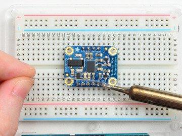
7 Assembly Prepare the header strip: Cut the strip to length if necessary. It will be easier to solder if you insert it into a breadboard - long pins down Adafruit Industries Page 7 of 29

). Adafruit Industries https://learn.adafruit.")
8 Add the breakout board: Place the breakout board over the pins so that the short pins poke through the breakout pads And Solder! Be sure to solder all pins for reliable electrical contact. Solder the longer power/data strip first (For tips on soldering, be sure to check out our Guide to Excellent Soldering ( Adafruit Industries Page 8 of 29


9 Adafruit Industries Page 9 of 29

10 You're done! Check your solder joints visually and continue onto the next steps Adafruit Industries Page 10 of 29

11 Arduino Code Wiring for Arduino You can easily wire this breakout to any microcontroller, we'll be using an Arduino. For another kind of microcontroller, just make sure it has I2C capability, then port the code - its pretty simple stuff! To connect the assembled BNO055 breakout to an Arduino Uno, follow the wiring diagram below. Connect Vin to the power supply, 3-5V is fine. Use the same voltage that the microcontroller logic is based off of. For most Arduinos, that is 5V Connect GND to common power/data ground Connect the SCL pin to the I2C clock SCL pin on your Arduino. On an UNO & '328 based Arduino, this is also known as A5, on a Mega it is also known as digital 21 and on a Leonardo/Micro, digital 3 Connect the SDA pin to the I2C data SDA pin on your Arduino. On an UNO & '328 based Arduino, this is also known as A4, on a Mega it is also known as digital 20 and on a Leonardo/Micro, digital 2 If you're using a Genuino Zero or Arduino Zero with the built in EDBG interface you may need to use I2C address 0x29 since 0x28 is 'taken' by the DBG chip Software The Adafruit_BNO055 driver supports reading raw sensor data, or you can use the Adafruit Unified Sensor system to retrieve orientation data in a standard data format. Download the Driver from Github To begin controling the motor chip, you will need to download the Adafruit_BNO055 Library from our github Adafruit Industries Page 11 of 29
12 repository. You can do that by visiting the github repo and manually downloading or, easier, just click this button to download the zip Download Adafruit_BNO055 from Github Rename the uncompressed folder Adafruit_BNO055 and check that the Adafruit_BNO055 folder contains Adafruit_BNO055.cpp and Adafruit_BNO055.h Place the Adafruit_BNO055 library folder your arduinosketchfolder/libraries/ folder. You may need to create the libraries subfolder if its your first library. Restart the IDE. We also have a great tutorial on Arduino library installation at: Download Adafruit_Sensor We also have a core sensor library that helps manage sensor readings. So, just like the BNO055 library, download Adafruit_Sensor Install just like you did with Adafruit_BNO055 Adafruit Unified Sensor System Download Adafruit_Sensor Since the Adafruit_BNO055 driver is based on the Adafruit Unified Sensor system, you can retrieve your three axis orientation data (in Euler angles) using the standard types and functions described in the Adafruit Sensor learning guide (.getevent,.getsensor, etc.). This is probably the easiest option if all you care about is absolute orientation data across three axis. For example, the following code snippet shows the core of what is needed to start reading data using the Unified Sensor System: Adafruit Industries Page 12 of 29
; Serial.println(\"\"); /* Initialise the sensor */ if(!bno.begin()) { /* There was a problem detecting the BNO055... check your connections */ Serial.")
13 #include <Wire.h> #include <Adafruit_Sensor.h> #include <Adafruit_BNO055.h> #include <utility/imumaths.h> Adafruit_BNO055 bno = Adafruit_BNO055(55); void setup(void) { Serial.begin(9600); Serial.println("Orientation Sensor Test"); Serial.println(""); /* Initialise the sensor */ if(!bno.begin()) { /* There was a problem detecting the BNO check your connections */ Serial.print("Ooops, no BNO055 detected... Check your wiring or I2C ADDR!"); while(1); } delay(1000); } bno.setextcrystaluse(true); void loop(void) { /* Get a new sensor event */ sensors_event_t event; bno.getevent(&event); /* Display the floating point data */ Serial.print("X: "); Serial.print(event.orientation.x, 4); Serial.print("\tY: "); Serial.print(event.orientation.y, 4); Serial.print("\tZ: "); Serial.print(event.orientation.z, 4); Serial.println(""); } delay(100); 'sensorapi' Example To test the Unified Sensor System output, open the sensorapi demo in the Adafruit_BNO055 examples folder: This should produce the following output on the Serial Monitor: Adafruit Industries Page 13 of 29
14 Raw Sensor Data If you don't want to use the Adafruit Unified Sensor system (for example if you want to access the raw accelerometer, magnetometer or gyroscope data directly before the sensor fusion algorithms process it), you can use the raw helper functions in the driver. The key raw data functions are: getvector (adafruit_vector_type_t vector_type) getquat (void) gettemp (void).getvector ( adafruit_vector_type_t vector_type ) The.getVector function accepts a single parameter (vector_type), which indicates what type of 3-axis vector data to return. The vector_type field can be one of the following values: VECTOR_MAGNETOMETER (values in ut, micro Teslas) VECTOR_GYROSCOPE (values in rps, radians per second) VECTOR_EULER (values in Euler angles or 'degrees', from ) VECTOR_ACCELEROMETER (values in m/s^2) VECTOR_LINEARACCEL (values in m/s^2) VECTOR_GRAVITY (values in m/s^2) For example, to get the Euler angles vector, we could run the following code: Adafruit Industries Page 14 of 29
15 imu::vector<3> euler = bno.getvector(adafruit_bno055::vector_euler); /* Display the floating point data */ Serial.print("X: "); Serial.print(euler.x()); Serial.print(" Y: "); Serial.print(euler.y()); Serial.print(" Z: "); Serial.print(euler.z()); Serial.println("");.getQuat(void) The.getQuat function returns a Quaternion, which is often easier and more accurate to work with than Euler angles when doing sensor fusion or data manipulation with raw sensor data. You can get a quaternion data sample via the following code: imu::quaternion quat = bno.getquat(); /* Display the quat data */ Serial.print("qW: "); Serial.print(quat.w(), 4); Serial.print(" qx: "); Serial.print(quat.y(), 4); Serial.print(" qy: "); Serial.print(quat.x(), 4); Serial.print(" qz: "); Serial.print(quat.z(), 4); Serial.println("");.getTemp(void) The.getTemp helper returns the current ambient temperature in degrees celsius, and can be read via the following function call: /* Display the current temperature */ int8_t temp = bno.gettemp(); Serial.print("Current Temperature: "); Serial.print(temp); Serial.println(" C"); Serial.println(""); 'rawdata' Example To test the raw data ouput, open the rawdata demo in the Adafruit_BNO055 examples folder: Adafruit Industries Page 15 of 29

; /* Display the floating point data */ Serial.print(\"X: \"); Serial.print(euler.x()); Serial.")
16 This should produce the following output on the Serial Monitor: By default, the sketch generates Euler angle absolute orientation data, but you can easily modify the data displayed by changing the value provided to.getvector below: // Possible vector values can be: // - VECTOR_ACCELEROMETER - m/s^2 // - VECTOR_MAGNETOMETER - ut // - VECTOR_GYROSCOPE - rad/s // - VECTOR_EULER - degrees // - VECTOR_LINEARACCEL - m/s^2 // - VECTOR_GRAVITY - m/s^2 imu::vector<3> euler = bno.getvector(adafruit_bno055::vector_euler); /* Display the floating point data */ Serial.print("X: "); Serial.print(euler.x()); Serial.print(" Y: "); Serial.print(euler.y()); Serial.print(" Z: "); Serial.print(euler.z()); Serial.println(""); Adafruit Industries Page 16 of 29
 and renders it using the data generated by the BNO055 sketch on the Uno.")
17 Processing Test To help you visualize the data, we've put together a basic Processing sketch that loads a 3D model (in the.obj file format) and renders it using the data generated by the BNO055 sketch on the Uno. The "bunny" sketch on the uno published data over UART, which the Processing sketch reads in, rotating the 3D model based on the incoming orientation data. Requirements Processing 2.x Note that you can try later Processing versions like 3.0+ too. On some platforms Processing has issues with supporting 3D acceleration (you might see 'NoClassDefFoundError: processing/awt/pgraphicsjava2d' errors). In those cases grab the later Processing 3.0+ release and use it instead of 2.x. Saito's OBJ Loader library for Processing (included as part of the Adafruit repo since Google Code is now 'End of Life'). G4P GUI library for Processing (download the latest version here and copy the zip into the processing libraries folder along with the OBJ loader library above). Version was used in this guide. The OBJ library is required to load 3D models. It isn't strictly necessary and you could also render a boring cube in Processing, but why play with cubes when you have rabbits?! Opening the Processing Sketch The processing sketch to render the 3D model is contained in the sample folder as the ahrs sketch for the Uno. With Processing open, navigate to you Adafruit_BNO055 library folder (ex.: 'libraries/adafruit_bno055'), and open 'examples/bunny/processing/cuberotate/cuberotate.pde'. You should see something like this in Processing: Adafruit Industries Page 17 of 29

18 Run the Bunny Sketch on the Uno Make sure that the "bunny" example sketch is running on the Uno, and that the Serial Monitor is closed. With the sample sketch running on the Uno, click the triangular 'play' icon in Processing to start the sketch. Rabbit Disco! You should see a rabbit similar to the following image: Adafruit Industries Page 18 of 29
.")
19 Before the rabbit will rotate you will need to click the : to the right of the serial port name. This will open a list of available serial ports, and you will need to click the appropriate serial port that your Arduino uses (check the Arduino IDE to see the port name if you're unsure). The chosen serial port should be remembered if you later run the sketch again. As you rotate your breakout board, the rabbit should rotate to reflect the movement of the breakout in 3D-space, as seen in the video below Adafruit Industries Page 19 of 29
20 Also notice in the upper right corner of the dialog box at the top that the calibration of each sensor is displayed. It's important to calibrate the BNO055 sensor so that the most accurate readings are retrieved. Each sensor on the board has a separate calibration status from 0 (uncalibrated) up to 3 (fully calibrated). Check out the video and information from this guide for how to best calibrate the BNO055 sensor. Adafruit Industries Page 20 of 29
21 Device Calibration The BNO055 includes internal algorithms to constantly calibrate the gyroscope, accelerometer and magnetometer inside the device. The exact nature of the calibration process is a black box and not fully documented, but you can read the calibration status of each sensor using the.getcalibration function in the Adafruit_BNO055 library. An example showing how to use this function can be found in the sensorapi demo, though the code is also shown below for convenience sake. The four calibration registers -- an overall system calibration status, as well individual gyroscope, magnetometer and accelerometer values -- will return a value between '0' (uncalibrated data) and '3' (fully calibrated). The higher the number the better the data will be. /**************************************************************************/ /* Display sensor calibration status */ /**************************************************************************/ void displaycalstatus(void) { /* Get the four calibration values (0..3) */ /* Any sensor data reporting 0 should be ignored, */ /* 3 means 'fully calibrated" */ uint8_t system, gyro, accel, mag; system = gyro = accel = mag = 0; bno.getcalibration(&system, &gyro, &accel, &mag); /* The data should be ignored until the system calibration is > 0 */ Serial.print("\t"); if (!system) { Serial.print("! "); } } /* Display the individual values */ Serial.print("Sys:"); Serial.print(system, DEC); Serial.print(" G:"); Serial.print(gyro, DEC); Serial.print(" A:"); Serial.print(accel, DEC); Serial.print(" M:"); Serial.println(mag, DEC); Interpretting Data The BNO055 will start supplying sensor data as soon as it is powered on. The sensors are factory trimmed to reasonably tight offsets, meaning you can get valid data even before the calibration process is complete, but particularly in NDOF mode you should discard data as long as the system calibration status is 0 if you have the choice. The reason is that system cal '0' in NDOF mode means that the device has not yet found the 'north pole', and orientation values will be off The heading will jump to an absolute value once the BNO finds magnetic north (the system calibration status jumps to 1 or higher). Adafruit Industries Page 21 of 29
22 When running in NDOF mode, any data where the system calibration value is '0' should generally be ignored Generating Calibration Data To generate valid calibration data, the following criteria should be met: Gyroscope: The device must be standing still in any position Magnetometer: In the past 'figure 8' motions were required in 3 dimensions, but with recent devices fast magnetic compensation takes place with sufficient normal movement of the device Accelerometer: The BNO055 must be placed in 6 standing positions for +X, -X, +Y, -Y, +Z and -Z. This is the most onerous sensor to calibrate, but the best solution to generate the calibration data is to find a block of wood or similar object, and place the sensor on each of the 6 'faces' of the block, which will help to maintain sensor alignment during the calibration process. You should still be able to get reasonable quality data from the BNO055, however, even if the accelerometer isn't entirely or perfectly calibrated. Persisting Calibration Data Once the device is calibrated, the calibration data will be kept until the BNO is powered off. The BNO doesn't contain any internal EEPROM, though, so you will need to perform a new calibration every time the device starts up, or manually restore previous calibration values yourself. Bosch Video Here's a video from the BNO055 makers on calibration! Adafruit Industries Page 22 of 29

23 CircuitPython Code It's easy to use the BNO055 sensor with CircuitPython and the Adafruit CircuitPython BNO055 library. This library allows you to easily write Python code that reads the acceleration and orientation of the sensor. First wire up a BNO055 to your board exactly as shown on the previous pages for Arduino using the I2C interface. Here's an example of wiring a Feather M0 to the sensor with I2C: Board 3V to sensor VIN Board GND to sensor GND Board SCL to sensor SCL Board SDA to sensor SDA Next you'll need to install the Adafruit CircuitPython BNO055 library on your CircuitPython board. Remember this module is for Adafruit CircuitPython firmware and not MicroPython.org firmware! First make sure you are running the latest version of Adafruit CircuitPython for your board. Next you'll need to install the necessary libraries to use the hardware--carefully follow the steps to find and install these libraries from Adafruit's CircuitPython library bundle. For example the Circuit Playground Express guide has a great page on how to install the library bundle for both express and non-express boards. Remember for non-express boards like the Trinket M0, Gemma M0, and Feather/Metro M0 basic you'll need to manually install the necessary libraries from the bundle: adafruit_bno055.mpy adafruit_bus_device adafruit_register Adafruit Industries Page 23 of 29
24 You can also download the adafruit_bno055.mpy from its releases page on Github. Before continuing make sure your board's lib folder or root filesystem has the adafruit_bno055.mpy, adafruit_bus_device, and adafruit_register files and folders copied over. Next connect to the board's serial REPL so you are at the CircuitPython >>> prompt. Usage To demonstrate the usage of the sensor we'll initialize it and read the acceleration, orientation (in Euler angles), and more from the board's Python REPL. First initialize the I2C bus and create an instance of the sensor by running: import board import busio import adafruit_bno055 i2c = busio.i2c(board.scl, board.sda) sensor = adafruit_bno055.bno055(i2c) Remember if you're using a board that doesn't support hardware I2C (like the ESP8266) you need to use the bitbangio module instead: import board import bitbangio import adafruit_bno055 i2c = bitbangio.i2c(board.scl, board.sda) sensor = adafruit_bno055.adafruit_bno055(i2c) Now you're ready to read values from the sensor using any of these properties: temperature - The sensor temperature in degrees Celsius. accelerometer - This is a 3-tuple of X, Y, Z axis accelerometer values in meters per second squared. magnetometer - This is a 3-tuple of X, Y, Z axis magnetometer values in microteslas. gyroscope - This is a 3-tuple of X, Y, Z axis gyroscope values in degrees per second. euler - This is a 3-tuple of orientation Euler angle values. quaternion - This is a 4-tuple of orientation quaternion values. linear_acceleration - This is a 3-tuple of X, Y, Z linear acceleration values (i.e. without effect of gravity) in meters per second squared. gravity - This is a 3-tuple of X, Y, Z gravity acceleration values (i.e. without the effect of linear acceleration) in meters per second squared. print('temperature: {} degrees C'.format(sensor.temperature)) print('accelerometer (m/s^2): {}'.format(sensor.accelerometer)) print('magnetometer (microteslas): {}'.format(sensor.magnetometer)) print('gyroscope (deg/sec): {}'.format(sensor.gyroscope)) print('euler angle: {}'.format(sensor.euler)) print('quaternion: {}'.format(sensor.quaternion)) print('linear acceleration (m/s^2): {}'.format(sensor.linear_acceleration)) print('gravity (m/s^2): {}'.format(sensor.gravity)) Adafruit Industries Page 24 of 29

25 That's all there is to using the BNO055 sensor with CircuitPython! Here's a complete example that prints the acceleration and orientation (as Euler angles) every second. Save this as main.py on your board and look for the output in the serial REPL. Remember if using the ESP8266 and bitbangio module you need to change the initialization as mentioned above! import board import busio import time import adafruit_bno055 # Initialize I2C and the sensor. i2c = busio.i2c(board.scl, board.sda) sensor = adafruit_bno055.bno055(i2c) # Main loop runs forever printing acceleration and Euler angles every second. while True: print('accelerometer (m/s^2): {}'.format(sensor.accelerometer)) print('euler angle: {}'.format(sensor.euler)) time.sleep(1.0) Adafruit Industries Page 25 of 29
26 FAQs Can I manually set the calibration constants? Yes you can save and restore the calibration of the sensor, check out the restore_offsets example: ffsets.ino One thing to keep in mind though is that the sensor isn't necessarily 'plug and play' with loading the calibration data, in particular the magnetometer needs to be recalibrated even if the offsets are loaded. The magnetometer calibration is very dynamic so saving the values once might not really help when they're reloaded and the EMF around the sensor has changed. For further details check out the datasheet and Bosch's info on the sensor for calibration info: 1/bno055_4 Does the device make any assumptions about its initial orientation? You can customize how the axes are oriented (i.e. swap them around, etc.) but the Adafruit Arduino library doesn't expose it right now. Check out section 3.4 Axis Remap of the BNO055 datasheet for info on the registers to adjust its orientation: 000_12.pdf Another thing to be aware of is that until the sensor calibrates it has a relative orientation output (i.e. orientation will be relative to where the sensor was when it powered on). A system status value of '0' in NDOF mode means that the device has not yet found the 'north pole', and orientation values will be relative not absolute. Once calibration and setup is complete (system status > '0') the heading will jump to an absolute value since the BNO has found magnetic north (the system calibration status jumps to 1 or higher). See the Device Calibration page in this learning guide for further details. Why doesn't Euler output seem to match the Quaternion output? The Euler angles coming out of the chip are based on 'automatic orientation detection', which has the drawback of not being continuous for all angles and situations. According to Bosch BNO055 Euler angle output should only be used for ecompass, where pitch and roll stay below 45 degrees. For absolute orientation, quaternions should always be used, and they can be converted to Euler angles at the last moment via the.toeuler() helper function in quaternion.h. I'm sometimes losing data over I2C, what can I do about this? Depending on your system setup, you might need to adjust the pullups on the SCL and SDA lines to be a bit stronger. The BNO055 has very tight timing requirements on the I2C bus, requiring short setup and rise times on the signals. By default the breakout board has 10K pullups, which might be too weak on some setups. You can shorten the rise times and extend the setup time on the I2C lines with 'stronger' pullups. To do this simply add a 3.3K pullup on SCL and a 2.2K pullup on the SDA line with a breadboard or perma-proto board, which will override to weaker 10K pullups that are populated by default. See the image below for details: Adafruit Industries Page 26 of 29

27 Adafruit Industries Page 27 of 29
28 Downloads Files Arduino Library EagleCAD PCB files on GitHub BNO055 Datasheet Fritzing object in the Adafruit Fritzing Library Pre-Compiled Bunny Rotate Binaries The following binary images can be used in place of running the Processing Sketch, and may help avoid the frequent API and plugin changes. For OS X download cuberotate.app.zip, which was built on OS X based on Processing 2.2.1: Schematic cuberotate.app.zip The latest version of the Adafruit BNO055 breakout can be seen below (click the image to view the schematic in full resolution): Board Dimensions The BNO055 breakout has the following dimensions (in inches): Adafruit Industries Page 28 of 29

29 Adafruit Industries Last Updated: :08:29 AM UTC Page 29 of 29
Adafruit BMP280 Barometric Pressure + Temperature Sensor Breakout
 Adafruit BMP280 Barometric Pressure + Temperature Sensor Breakout Created by lady ada Last updated on 2017-12-09 06:21:37 PM UTC Guide Contents Guide Contents Overview Pinouts Power Pins: SPI Logic pins:
Adafruit HMC5883L Breakout - Triple-Axis Magnetometer Compass Sensor
 Adafruit HMC5883L Breakout - Triple-Axis Magnetometer Compass Sensor Created by lady ada Last updated on 2016-09-14 07:05:05 PM UTC Guide Contents Guide Contents Overview Pinouts Assembly Prepare the header
Adafruit BME680. Created by lady ada. Last updated on :10:23 AM UTC
 Adafruit BME680 Created by lady ada Last updated on 2018-01-22 05:10:23 AM UTC Guide Contents Guide Contents Overview Pinouts Power Pins: SPI Logic pins: I2C Logic pins: Assembly Prepare the header strip:
Adafruit DS3231 Precision RTC Breakout
 Adafruit DS3231 Precision RTC Breakout Created by lady ada Last updated on 2016-02-05 04:43:25 PM EST Guide Contents Guide Contents Overview Pinouts Power Pins: I2C Logic pins: Other Pins: Assembly Prepare
Adafruit VL53L0X Time of Flight Micro-LIDAR Distance Sensor Breakout
 Adafruit VL53L0X Time of Flight Micro-LIDAR Distance Sensor Breakout Created by lady ada Last updated on 2016-12-05 06:40:45 PM UTC Guide Contents Guide Contents Overview Sensing Capablities Pinouts Power
Adafruit SHT31-D Temperature & Humidity Sensor Breakout
 Adafruit SHT31-D Temperature & Humidity Sensor Breakout Created by lady ada Last updated on 2016-09-16 07:45:55 PM UTC Guide Contents Guide Contents Overview Pinouts Power Pins: I2C Logic pins: Other Pins:
Adafruit LSM9DS1 Accelerometer + Gyro + Magnetometer 9-DOF Breakout
 Adafruit LSM9DS1 Accelerometer + Gyro + Magnetometer 9-DOF Breakout Created by lady ada Last updated on 2018-08-17 09:59:41 PM UTC Guide Contents Guide Contents Overview Pinouts Power Pins I2C Pins SPI
Adafruit BME280 Humidity + Barometric Pressure + Temperature Sensor Breakout
 Adafruit BME280 Humidity + Barometric Pressure + Temperature Sensor Breakout Created by lady ada Last updated on 2018-08-22 03:49:22 PM UTC Guide Contents Guide Contents Overview Pinouts Power Pins: SPI
Adafruit 1-Wire Thermocouple Amplifier - MAX31850K
 Adafruit 1-Wire Thermocouple Amplifier - MAX31850K Created by lady ada Last updated on 2018-08-22 03:40:09 PM UTC Guide Contents Guide Contents Overview Pinouts Power Pins Address Pins Data Pin Themocouple
Adafruit HTU21D-F Temperature & Humidity Sensor
 Adafruit HTU21D-F Temperature & Humidity Sensor Created by lady ada Last updated on 2014-07-26 01:30:08 PM EDT Guide Contents Guide Contents Overview Pinouts Power Pins: I2C Logic pins: Assembly Prepare
Adafruit LSM9DS0 Accelerometer + Gyro + Magnetometer 9-DOF Breakouts
 Adafruit LSM9DS0 Accelerometer + Gyro + Magnetometer 9-DOF Breakouts Created by lady ada Last updated on 2018-08-11 09:54:22 PM UTC Guide Contents Guide Contents Overview Pinouts Flora Sewable Version
Adafruit BME280 Humidity + Barometric Pressure + Temperature Sensor Breakout
 Adafruit BME280 Humidity + Barometric Pressure + Temperature Sensor Breakout Created by lady ada Last updated on 2017-01-11 09:01:04 PM UTC Guide Contents Guide Contents Overview Pinouts Power Pins: SPI
Adafruit 4-Channel ADC Breakouts
 Adafruit 4-Channel ADC Breakouts Created by Bill Earl Last updated on 2017-11-21 02:03:21 AM UTC Guide Contents Guide Contents Overview ADS1115 Features: ADS1015 Features: Assembly and Wiring Assembly:
Adafruit INA219 Current Sensor Breakout
 Adafruit INA219 Current Sensor Breakout Created by lady ada Last updated on 2018-01-17 05:25:30 PM UTC Guide Contents Guide Contents Overview Why the High Side? How does it work? Assembly Addressing the
Adafruit 1-Wire Thermocouple Amplifier - MAX31850K
 Adafruit 1-Wire Thermocouple Amplifier - MAX31850K Created by lady ada Last updated on 2015-04-09 03:45:15 PM EDT Guide Contents Guide Contents Overview Pinouts Power Pins Address Pins Data Pin Themocouple
Adafruit MAX31865 RTD PT100 or PT1000 Amplifier
 Adafruit MAX31865 RTD PT100 or PT1000 Amplifier Created by lady ada Last updated on 2017-12-02 12:08:40 AM UTC Guide Contents Guide Contents Overview Pinouts Power Pins: SPI Logic pins: Sensor Terminal
ADXL343 Breakout Learning Guide
 ADXL343 Breakout Learning Guide Created by Kevin Townsend Last updated on 2019-02-19 07:38:05 PM UTC Guide Contents Guide Contents Overview Technical Characteristics Pinout Power Pins Digital Pins Assembly
Bosch BMP085 Breakout Board
 Bosch BMP085 Breakout Board Created by lady ada Last updated on 2014-11-07 03:00:29 PM EST Guide Contents Guide Contents Overview Specifications Wiring the BMP085 Using the BMP085 (API v2) Using the BMP085
Adafruit MAX31865 RTD PT100 or PT1000 Amplifier
 Adafruit MAX31865 RTD PT100 or PT1000 Amplifier Created by lady ada Last updated on 2018-08-22 03:57:30 PM UTC Guide Contents Guide Contents Overview Pinouts Power Pins: SPI Logic pins: Sensor Terminal
Adafruit CAP1188 Breakout
 Adafruit CAP1188 Breakout Created by lady ada Last updated on 2014-05-14 12:00:10 PM EDT Guide Contents Guide Contents Overview Pinouts Power pins I2C interface pins SPI inteface pins Other interfacing
TMP36 Temperature Sensor
 TMP36 Temperature Sensor Created by lady ada Last updated on 2017-11-26 10:17:46 PM UTC Guide Contents Guide Contents Overview Some Basic Stats How to Measure Temperature Problems you may encounter with
Adafruit seesaw. Created by Dean Miller. Last updated on :30:23 AM UTC
 Adafruit seesaw Created by Dean Miller Last updated on 2018-03-17 12:30:23 AM UTC Guide Contents Guide Contents Overview Pinouts Power Pins: Logic Pins: GPIO Pins: Neopixel Pins: Address Pins: ADC Pins:
TSL2561 Luminosity Sensor
 TSL2561 Luminosity Sensor Created by lady ada Last updated on 2015-06-12 12:10:28 PM EDT Guide Contents Guide Contents Overview Wiring the TSL2561 Sensor Using the TSL2561 Sensor Downloads Buy a TSL2561
Stand-alone programming AVRs using CircuitPython
 Stand-alone programming AVRs using CircuitPython Created by lady ada Last updated on 2018-01-25 11:53:17 PM UTC Guide Contents Guide Contents Overview Supported Chips Wiring Power Pins Data Pins Wiring
Adafruit Terminal Block Breakout FeatherWing
 Adafruit Terminal Block Breakout FeatherWing Created by lady ada Last updated on 2017-01-04 04:53:26 AM UTC Guide Contents Guide Contents Overview Pinouts Assembly Downloads Datasheets & Files Schematic
Adafruit Metro Mini. Created by lady ada. Last updated on :12:28 PM UTC
 Adafruit Metro Mini Created by lady ada Last updated on 2018-01-24 08:12:28 PM UTC Guide Contents Guide Contents Overview Pinouts USB & Serial converter Microcontroller & Crystal LEDs Power Pins & Regulators
Adafruit Mini TFT " 160x80
 Adafruit Mini TFT - 0.96" 160x80 Created by lady ada Last updated on 2017-07-14 05:24:22 AM UTC Guide Contents Guide Contents Overview Pinouts Assembly Prepare the header strip: Add the board: And Solder!
MAG3110 Magnetometer Hookup Guide
 MAG3110 Magnetometer Hookup Guide CONTRIBUTORS: AGLASS0FMILK FAVORITE 0 Introduction The SparkFun MAG3110 Triple Axis Magnetometer is a breakout board for the 3-axis magnetometer from NXP/Freescale. It
Adafruit 1-Wire GPIO Breakout - DS2413
 Adafruit 1-Wire GPIO Breakout - DS2413 Created by Bill Earl Last updated on 2018-08-22 03:40:00 PM UTC Guide Contents Guide Contents Overview Assembly & Wiring Headers Position the Header And Solder! Wiring
Adafruit Optical Fingerprint Sensor
 Adafruit Optical Fingerprint Sensor Created by lady ada Last updated on 2017-11-27 12:27:09 AM UTC Guide Contents Guide Contents Overview Enrolling vs. Searching Enrolling New Users with Windows Searching
Introducting Itsy Bitsy 32u4
 Introducting Itsy Bitsy 32u4 Created by lady ada Last updated on 2018-01-03 05:47:20 AM UTC Guide Contents Guide Contents Overview Pinouts Which do you have? Power Pins Adafruit Pro Trinket LiIon/LiPoly
Grove - 3 Axis Digital Accelerometer±16g Ultra-low Power (BMA400)
") Grove - 3 Axis Digital Accelerometer±16g Ultra-low Power (BMA400) The Grove - 3-Axis Digital Accelerometer ±16g Ultra-low Power (BMA400) sensor is a 12 bit, digital, triaxial acceleration sensor with smart
Grove - 3 Axis Digital Accelerometer±16g Ultra-low Power (BMA400) The Grove - 3-Axis Digital Accelerometer ±16g Ultra-low Power (BMA400) sensor is a 12 bit, digital, triaxial acceleration sensor with smart
BNO055 Quick start guide
 BNO055 Quick start guide Bosch Sensortec Application note: BNO055 Quick start guide Document revision 1.0 Document release date Document number Mar.2015 BST-BNO055-AN007-00 Technical reference code 0 273
DS1307 Real Time Clock Breakout Board Kit
 DS1307 Real Time Clock Breakout Board Kit Created by Tyler Cooper Last updated on 2016-09-07 12:03:17 AM UTC Guide Contents Guide Contents Overview What is an RTC? Battery Backup CR1220 12mm Diameter -
mcube Proprietary APS v1.0 1 / mcube Inc. All rights reserved.
 GENERAL DESCRIPTION The MC3672 is an ultra-low power, low noise, integrated digital output 3-axis accelerometer with a feature set optimized for wearables and consumer product motion sensing. Applications
Arduino Uno. Power & Interface. Arduino Part 1. Introductory Medical Device Prototyping. Digital I/O Pins. Reset Button. USB Interface.
 Introductory Medical Device Prototyping Arduino Part 1, http://saliterman.umn.edu/ Department of Biomedical Engineering, University of Minnesota Arduino Uno Power & Interface Reset Button USB Interface
LIS3DH Hookup Guide. Introduction. SparkFun Triple Axis Accelerometer Breakout - LIS3DH SEN Required Materials
 Page 1 of 15 LIS3DH Hookup Guide Introduction The LIS3DH is a triple axis accelerometer you can use to add translation detection to your project. It would be classified as a 3DoF, or 3 Degrees of Freedom.
2.2" TFT Display. Created by lady ada. Last updated on :19:15 PM UTC
 2.2" TFT Display Created by lady ada Last updated on 2017-12-22 11:19:15 PM UTC Guide Contents Guide Contents Overview Pinouts Assembly Arduino Wiring Arduino UNO or Compatible Wiring Wiring for Other
Grove - 6-Axis Accelerometer&Gyroscope(BMI088)
") Grove - 6-Axis Accelerometer&Gyroscope(BMI088) The Grove - 6-Axis Accelerometer&Gyroscope(BMI088) is a 6 DoF(degrees of freedom) Highperformance Inertial Measurement Unit(IMU).This sensor is based on BOSCH
Grove - 6-Axis Accelerometer&Gyroscope(BMI088) The Grove - 6-Axis Accelerometer&Gyroscope(BMI088) is a 6 DoF(degrees of freedom) Highperformance Inertial Measurement Unit(IMU).This sensor is based on BOSCH
Metro Minimalist Clock
 Metro Minimalist Clock Created by John Park Last updated on 2018-08-22 04:01:22 PM UTC Guide Contents Guide Contents Overview For this build you'll need: Clock Circuit Code the Clock Display the Clock
TMP36 Temperature Sensor
 TMP36 Temperature Sensor Created by Ladyada Last updated on 2013-07-30 05:30:36 PM EDT Guide Contents Guide Contents 2 Overview 3 Some Basic Stats 4 These stats are for the temperature sensor in the Adafruit
Adafruit Analog Accelerometer Breakouts
 Adafruit Analog Accelerometer Breakouts Created by Bill Earl Last updated on 2017-12-20 04:37:08 PM UTC Guide Contents Guide Contents Overview How it Works: MEMS - Micro Electro-Mechanical Systems Ratiometric
1.5" & 2.1" Monochrome 128x64 OLED Display Module
 1.5" & 2.1" Monochrome 128x64 OLED Display Module Created by lady ada Last updated on 2018-11-29 04:47:33 PM UTC Guide Contents Guide Contents Overview Pinouts Power Pins Signal Pins Remaining Pins Assembly
Adafruit TB A DC/Stepper Motor Driver Breakout Board
 Adafruit TB6612 1.2A DC/Stepper Motor Driver Breakout Board Created by lady ada Last updated on 2016-10-01 06:35:33 PM UTC Guide Contents Guide Contents Overview Pinouts Power Pins Signal in Pins Motor
2.3" Monochrome 128x32 OLED Display Module
 2.3" Monochrome 128x32 OLED Display Module Created by lady ada Last updated on 2018-08-22 03:49:39 PM UTC Guide Contents Guide Contents Overview Pinouts Power Pins Signal Pins Remaining Pins Assembly Changing
micro:bit Lesson 1. Using the Built-in Sensors
 micro:bit Lesson 1. Using the Built-in Sensors Created by Simon Monk Last updated on 2018-03-02 05:46:13 PM UTC Guide Contents Guide Contents Overview Magnetometer Magnet Detector High-strength 'rare earth'
Adafruit USB Power Gauge Mini-Kit
 Adafruit USB Power Gauge Mini-Kit Created by Bill Earl Last updated on 2017-07-14 11:55:04 PM UTC Guide Contents Guide Contents Overview Assembly Basic Assembly Solder the female connector. Solder the
Adafruit Optical Fingerprint Sensor
 Adafruit Optical Fingerprint Sensor Created by lady ada Last updated on 2018-08-22 03:32:31 PM UTC Guide Contents Guide Contents Overview Enrolling vs. Searching Enrolling New Users with Windows Searching
Adafruit 2.4" Color TFT Touchscreen Breakout
 Adafruit 2.4" Color TFT Touchscreen Breakout Created by lady ada Last updated on 2016-09-30 12:51:56 AM UTC Guide Contents Guide Contents Overview Pinouts SPI Mode Resistive touch pins 8-Bit Mode Assembly
GENERAL DESCRIPTION MC3635 FEATURES
 Quick Start Guide and Demo GENERAL DESCRIPTION The MC3635 is an ultra-low power, lownoise, integrated digital output 3-axis accelerometer with a feature set optimized for wearables and consumer product
MC3635 FEATURES GENERAL DESCRIPTION
 GENERAL DESCRIPTION MC3635 FEATURES The MC3635 is an ultra-low power, low noise, integrated digital output 3-axis accelerometer with a feature set optimized for wearables and the Internet of Moving Things
Selection and Integration of Sensors Alex Spitzer 11/23/14
 Selection and Integration of Sensors Alex Spitzer aes368@cornell.edu 11/23/14 Sensors Perception of the outside world Cameras, DVL, Sonar, Pressure Accelerometers, Gyroscopes, Magnetometers Position vs
Adafruit 3.5" 320x480 Color TFT Touchscreen Breakout
 Adafruit 3.5" 320x480 Color TFT Touchscreen Breakout Created by lady ada Last updated on 2017-01-30 01:59:14 AM UTC Guide Contents Guide Contents Overview Pinouts SPI Mode 8-Bit Mode Wiring & Test Assembling
Circuit Playground Express: Piano in the Key of Lime
 Circuit Playground Express: Piano in the Key of Lime Created by Kattni Rembor Last updated on 2017-10-21 09:59:14 PM UTC Guide Contents Guide Contents Overview Required parts Meet Circuit Playground Express
Adafruit Analog Accelerometer Breakouts
 Adafruit Analog Accelerometer Breakouts Created by Bill Earl Last updated on 2016-0-0 07:03:24 AM EDT Guide Contents Guide Contents Overview How it Works: MEMS - Micro Electro-Mechanical Systems Ratiometric
MMA8452Q Accelerometer Breakout Hookup Guide
 Page 1 of 11 MMA845Q Accelerometer Breakout Hookup Guide CONTRIBUTORS: JIMB0 Introduction Freescale s MMA845Q is a smart, low-power, three-axis, capacitive micromachined accelerometer with 1 bits of resolution.
Adafruit 5" and 7" 800x480 TFT HDMI Backpack
 Adafruit 5" and 7" 800x480 TFT HDMI Backpack Created by lady ada Last updated on 2017-10-22 09:01:29 PM UTC Guide Contents Overview Pinouts EDID EEPROM Port Backlight Control Power Output Raspberry Pi
Adafruit OLED FeatherWing
 Adafruit OLED FeatherWing Created by lady ada Last updated on 2018-06-05 04:52:24 AM UTC Guide Contents Guide Contents Overview Pinouts Power Pins I2C Data Pins Optional Buttons Reset Button Assembly Prepare
2.3" Monochrome 128x32 OLED Display Module
 2.3" Monochrome 128x32 OLED Display Module Created by lady ada Last updated on 2017-08-21 08:12:27 PM UTC Guide Contents Guide Contents Overview Pinouts Power Pins Signal Pins Remaining Pins Assembly Changing
Introduction to Arduino (programming, wiring, and more!)
") Introduction to Arduino (programming, wiring, and more!) James Flaten, MN Space Grant Consortium with Ben Geadelmann, Austin Langford, et al. University of MN Twin Cities Aerospace Engineering and Mechanics
Introduction to Arduino (programming, wiring, and more!) James Flaten, MN Space Grant Consortium with Ben Geadelmann, Austin Langford, et al. University of MN Twin Cities Aerospace Engineering and Mechanics
1.5" & 2.1" Monochrome 128x64 OLED Display Module
 1.5" & 2.1" Monochrome 128x64 OLED Display Module Created by lady ada Last updated on 2016-02-16 11:27:52 AM EST Guide Contents Guide Contents Overview Pinouts Power Pins Signal Pins Remaining Pins Assembly
Adafruit PDM Microphone Breakout
 Adafruit PDM Microphone Breakout Created by lady ada Last updated on 2018-01-10 10:25:53 PM UTC Guide Contents Guide Contents Overview Pinouts Wiring & Test Available I2S Pins Install Library Downloads
Arduino Uno Microcontroller Overview
 Innovation Fellows Program Arduino Uno Microcontroller Overview, http://saliterman.umn.edu/ Department of Biomedical Engineering, University of Minnesota Arduino Uno Power & Interface Reset Button USB
Adafruit OLED FeatherWing
 Adafruit OLED FeatherWing Created by lady ada Last updated on 2016-09-15 07:13:44 PM UTC Guide Contents Guide Contents Overview Pinouts Power Pins I2C Data Pins Optional Buttons Reset Button Assembly Prepare
Gravity: BMI160 6-Axis Inertial Motion Sensor SKU: SEN0250
 Gravity: BMI160 6-Axis Inertial Motion Sensor SKU: SEN0250 Introduction The BMI160 6-axis inertial motion sensor is a new product from DFRobot. It is based on Bosch BMI160 6-axis MEMS sensor which integrates
Circuit Playground Firmata
 Circuit Playground Firmata Created by Tony DiCola Last updated on 2018-08-22 03:53:36 PM UTC Guide Contents Guide Contents Overview Firmata Sketch Example Python Code Install Dependencies Python Circuit
Pedometer 3 Click. PID: MIKROE 3259 Weight: 24 g
 Pedometer 3 Click PID: MIKROE 3259 Weight: 24 g The Pedometer 3 click is a tri-axis acceleration sensing Click board utilizing the KX126-1063. An advanced three-axis acceleration sensor, the KX126-1063
#include "quaternionfilters.h" #include "MPU9250.h" data read #define SerialDebug true // Set to true to get Serial output for debugging
 /*Hardware setup: MPU9250 Breakout --------- Arduino VDD ---------------------- 3.3V VDDI --------------------- 3.3V SDA ----------------------- A4 SCL ----------------------- A5 GND ----------------------
Inertial Measurement Units I!
 ! Inertial Measurement Units I! Gordon Wetzstein! Stanford University! EE 267 Virtual Reality! Lecture 9! stanford.edu/class/ee267/!! Lecture Overview! coordinate systems (world, body/sensor, inertial,
Adafruit Ethernet FeatherWing
 Adafruit Ethernet FeatherWing Created by lady ada Last updated on 2017-07-14 05:32:28 AM UTC Guide Contents Guide Contents Overview Pinouts Power Pins SPI Data Pins Other Breakouts Assembly Prepare the
CyberAtom X-202 USER MANUAL. Copyrights Softexor 2015 All Rights Reserved.
 CyberAtom X-202 USER MANUAL Copyrights Softexor 2015 All Rights Reserved. X-202 Contents ii Contents About...5 Block Diagram... 5 Axes Conventions...5 System Startup... 6 Hardware Reset...6 LED indicator...
Introducing Circuit Playground
 Introducing Circuit Playground Created by lady ada Last updated on 2017-10-22 10:36:23 PM UTC Guide Contents Guide Contents Overview Classic vs. Express How to tell if you have a Classic How to tell if
Proper Debugging of ATSAMD21 Processors
 Proper Debugging of ATSAMD21 Processors Created by lady ada Last updated on 2017-06-08 06:47:17 PM UTC Guide Contents Guide Contents Overview Install Software Arduino IDE J-Link Software Atmel Studio 7
Adafruit Feather 32u4 Basic Proto
 Adafruit Feather 32u4 Basic Proto Created by lady ada Last updated on 2018-05-27 09:32:48 PM UTC Guide Contents Guide Contents Overview Pinouts Power Pins Logic pins Other Pins! Assembly Header Options!
IR Breakbeam Sensors. Created by lady ada. Last updated on :32:59 PM UTC
 IR Breakbeam Sensors Created by lady ada Last updated on 2017-12-08 10:32:59 PM UTC Guide Contents Guide Contents Overview Arduino CircuitPython 2 3 5 8 Adafruit Industries https://learn.adafruit.com/ir-breakbeam-sensors
Arduino Dock 2. The Hardware
 Arduino Dock 2 The Arduino Dock 2 is our supercharged version of an Arduino Uno R3 board. These two boards share the same microcontroller, the ATmel ATmega328P microcontroller (MCU), and have identical
How Tall Is It? Created by Carter Nelson. Last updated on :56:46 PM UTC
 How Tall Is It? Created by Carter Nelson Last updated on 2018-08-22 03:56:46 PM UTC Guide Contents Guide Contents Overview Required Parts Other Items Before Starting Circuit Playground Classic Circuit
Parallax LSM9DS1 9-axis IMU Module (#28065)
") Web Site: www.parallax.com Forums: forums.parallax.com Sales: sales@parallax.com Technical:support@parallax.com Office: (916) 624-8333 Fax: (916) 624-8003 Sales: (888) 512-1024 Tech Support: (888) 997-8267
Web Site: www.parallax.com Forums: forums.parallax.com Sales: sales@parallax.com Technical:support@parallax.com Office: (916) 624-8333 Fax: (916) 624-8003 Sales: (888) 512-1024 Tech Support: (888) 997-8267
ITG-3200 Hookup Guide
 Page 1 of 9 ITG-300 Hookup Guide Introduction This is a breakout board for InvenSense s ITG-300, a groundbreaking triple-axis, digital output gyroscope. The ITG-300 features three 16-bit analog-to-digital
AT42QT101X Capacitive Touch Breakout Hookup Guide
 Page 1 of 10 AT42QT101X Capacitive Touch Breakout Hookup Guide Introduction If you need to add user input without using a button, then a capacitive touch interface might be the answer. The AT42QT1010 and
Adafruit INA219 Current Sensor Breakout
 Adafruit INA219 Current Sensor Breakout Created by lady ada Last updated on 2015-01-01 08:30:10 AM EST Guide Contents Guide Contents Overview Why the High Side? How does it work? Assembly Addressing the
keyestudio Keyestudio MEGA 2560 R3 Board
 Keyestudio MEGA 2560 R3 Board Introduction: Keyestudio Mega 2560 R3 is a microcontroller board based on the ATMEGA2560-16AU, fully compatible with ARDUINO MEGA 2560 REV3. It has 54 digital input/output
Using the BMP085/180 with Raspberry Pi or Beaglebone Black
 Using the BMP085/180 with Raspberry Pi or Beaglebone Black Created by Kevin Townsend Last updated on 2014-06-28 08:31:07 PM EDT Guide Contents Guide Contents Overview A Note on Distributions Configuring
ESPino - Specifications
 ESPino - Specifications Summary Microcontroller ESP8266 (32-bit RISC) WiFi 802.11 (station, access point, P2P) Operating Voltage 3.3V Input Voltage 4.4-15V Digital I/O Pins 9 Analog Input Pins 1 (10-bit
Adafruit PowerBoost Charger
 Adafruit PowerBoost 500 + Charger Created by lady ada Last updated on 2017-06-01 04:08:36 PM UTC Guide Contents Guide Contents Overview Pinouts Power Pins Control Pins LEDs Battery and USB connection On/Off
Arduino ADK Rev.3 Board A000069
 Arduino ADK Rev.3 Board A000069 Overview The Arduino ADK is a microcontroller board based on the ATmega2560 (datasheet). It has a USB host interface to connect with Android based phones, based on the MAX3421e
Getting Started with the nrf8001 Bluefruit LE Breakout
 Getting Started with the nrf8001 Bluefruit LE Breakout Created by Kevin Townsend Last updated on 2016-09-15 05:04:14 PM UTC Guide Contents Guide Contents Introduction Requirements Pinouts Hooking Everything
Micro SD Card Breakout Board Tutorial
 Micro SD Card Breakout Board Tutorial Created by lady ada Last updated on 2017-11-26 10:01:55 PM UTC Guide Contents Guide Contents Introduction Look out! What to watch for! Formatting notes Wiring Arduino
Adafruit INA219 Current Sensor Breakout
 Adafruit INA219 Current Sensor Breakout Created by Ladyada Last updated on 2013-09-12 10:15:19 AM EDT Guide Contents Guide Contents Overview Why the High Side? How does it work? Assembly Addressing the
Adafruit HUZZAH32 - ESP32 Feather
 Adafruit HUZZAH32 - ESP32 Feather Created by lady ada Last updated on 2017-09-03 05:32:24 PM UTC Guide Contents Guide Contents Overview Pinouts Power Pins Logic pins Serial pins I2C & SPI pins GPIO & Analog
Adafruit 20W Stereo Audio Amplifier - MAX9744
 Adafruit 20W Stereo Audio Amplifier - MAX9744 Created by lady ada Last updated on 2017-07-14 06:10:43 AM UTC Guide Contents Guide Contents Overview Pinouts Power connections Audio Inputs Speaker outputs
Adafruit I2S MEMS Microphone Breakout
 Adafruit I2S MEMS Microphone Breakout Created by lady ada Last updated on 2017-04-03 08:44:00 PM UTC Guide Contents Guide Contents Overview Assembly Prepare the header strip: Add the breakout board: And
Thumb Joystick Retail. Tools and parts you'll need. Things you'll want to know. How does it work? Skill Level: Beginner. by MikeGrusin March 22, 2011
 Thumb Joystick Retail Skill Level: Beginner by MikeGrusin March 22, 2011 Thank you for purchasing our Thumb Joystick! Whether you're blasting aliens or driving a robot, you'll find it a very useful addition
36mm LED Pixels. Created by Phillip Burgess. Last updated on :45:20 PM EDT
 36mm LED Pixels Created by Phillip Burgess Last updated on 2013-07-26 03:45:20 PM EDT Guide Contents Guide Contents Overview Project Ideas Wiring Powering Code Installation Using the Library Troubleshooting
CyberAtom X-200 USER MANUAL. Copyrights Softexor 2015 All Rights Reserved.
 CyberAtom X-200 USER MANUAL Copyrights Softexor 2015 All Rights Reserved. X-200 Contents ii Contents About...6 Block Diagram... 6 Axes Conventions...6 System Startup... 7 Selecting Power Source...7 Hardware
ZX Distance and Gesture Sensor SMD Hookup Guide
 Page 1 of 16 ZX Distance and Gesture Sensor SMD Hookup Guide Introduction The ZX Distance and Gesture Sensor is a collaboration product with XYZ Interactive. The innovative people at XYZ Interactive have
2011 FIRST Robotics Competition Sensor Manual
 2011 FIRST Robotics Competition Sensor Manual The 2011 FIRST Robotics Competition (FRC) sensors are outlined in this document. It is being provided as a courtesy, and therefore does not supersede any information
Introducing Pro Trinket
 Introducing Pro Trinket Created by lady ada Last updated on 2018-01-11 09:10:40 PM UTC Guide Contents Guide Contents Overview Guided Tour Pinouts Power Pins GPIO Pins Logic Level The Digital Only GPIO
Arduino Uno. Arduino Uno R3 Front. Arduino Uno R2 Front
 Arduino Uno Arduino Uno R3 Front Arduino Uno R2 Front Arduino Uno SMD Arduino Uno R3 Back Arduino Uno Front Arduino Uno Back Overview The Arduino Uno is a microcontroller board based on the ATmega328 (datasheet).
Accel 5 click. PID: MIKROE 3149 Weight: 24 g
 Accel 5 click PID: MIKROE 3149 Weight: 24 g Accel 5 click features an ultra-low power triaxial accelerometer sensor, labeled as the BMA400. This Click board allows linear motion and gravitational force