Scan Acceleration with Rapid Gradient-Echo
|
|
|
- Wilfrid Carpenter
- 6 years ago
- Views:
Transcription
1 Scan Acceleration with Rapid Gradient-Echo Hsiao-Wen Chung ( 鍾孝文 ), Ph.D., Professor Dept. Electrical Engineering, National Taiwan Univ. Dept. Radiology, Tri-Service General Hospital 1 of 214
2 The Need for Faster Scan Patient comfort, motion artifacts, efficiency, more information EPI? You know the difficulty now But there are a lot more ways to accelerate the scanning 2 of 214
3 Back to the Old Formula Scan time for single slice = TR x (# phase encoding) x NEX Reduce phase encoding A little faster, trade in resolution Reduce NEX (1 or 0.5 at most) 3 of 214
4 MRI Scan Time (1990?) Spin-echo : 256x256, 2 NEX PD, T2 : 16 min (TR 2000) T1 : 5 min (TR 600) Note : somewhat exaggerated 4 of 214
5 Short Scan Time? Reduce TR ( msec?) 40 times faster? 256x256, 1 NEX : 13 sec Sounds like an efficient way? 5 of 214
6 Short Scan Time? Reduce TR Increased T1-weighting Reduced SNR 6 of 214
7 Signal Intensity Effects of Reduced TR on T1 Contrast Signal at this TR TR Substantial reduction in TR leads to SNR loss 7 of 214
8 How Low Is The SNR? TR = T1 : ~ 63% of thermal equilibrium TR = 0.1 T1 : ~ 9.5% of thermal equilibrium 8 of 214
9 Compensating SNR? SNR loss due to slow T1 recovery CSF T1 = 0.7 ~ 4.0 sec Can magnetization recover from nonzero (positive) values? Can we retain Mz after RF pulsing? 9 of 214
10 Small Flip Angle RF Excitation B o z' z' B o y' y' x' x' Mxy for data acquisition, some Mz for next excitation 10 of 214
11 The FLASH Technique Reducing TR without sacrificing too much SNR Achievable by lowering the flip angle via B1 amplitude adjustment Fast Low-Angle SHot (FLASH) Haase et al., of 214
12 SNR Comparison TR = T1, a = 90 0 : ~ 63% of Mo TR = 0.1 T1 : a = 90 0 : ~ 9.5% of Mo a = 25 0 : ~ 22% of Mo 12 of 214
13 Example CSF has T1 ~ 700 msec TR lowered to ~ 70 msec Slightly lowered quality Scan time ~ 18 sec allows breath-hold exams 13 of 214
14 Here Comes A Question Spin-echo no longer useable! Imaging has to be done with gradient-echo Bo inhomogeneity is going to affect image quality But can also become another source of diagnostic information 14 of 214
15 Effects of Refocusing Pulse z' z' B o B o x' y' x' y' Mz becomes negative (recovery takes even longer)! 15 of 214
16 Gradient-Echo Properties No refocusing function from pulse Image affected by Bo inhomogeneity T2* decaying (not T2) Instrumentation, air-tissue interface Hemorrhage, hematoma, bone 16 of 214

17 Effects of Bo inhomogeneity Image voxel : Non-uniform Bo in a voxel short T2* 17 of 214

18 Effects of TE TE = 9 msec TE = 18 msec 18 of 214
19 Gradient-echo Is Worse? Image quality for gradient-echo is often harder to control than for spin-echo But that does not mean bad Proper usage gives useful information that cannot be provided by spin-echo 19 of 214
20 Application Examples Hemorrhage (Iron in blood) Brain perfusion (Gd-based agent) Blood oxygenation (deoxy-hb) Brain fmri (BOLD contrast) 20 of 214


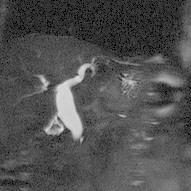
21 T2* Signal Loss in Hemorrhage T1 PD T2 GrE 21 of 214


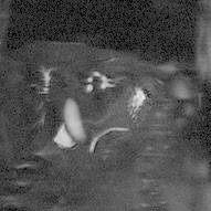
22 T2* Signal Loss & Blood Oxygenation Normal air Pure oxygen 22 of 214
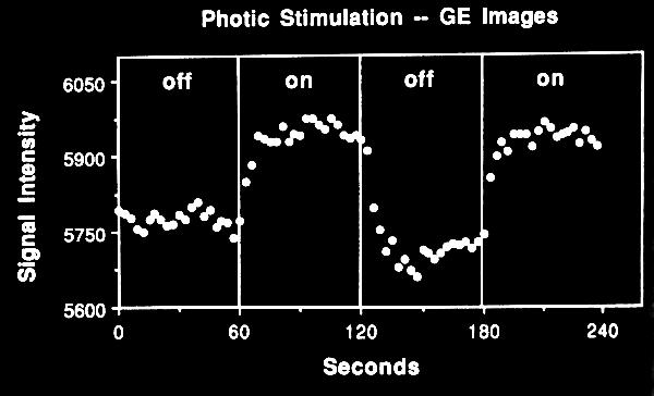
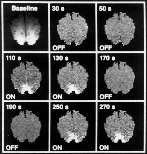
23 Brain Oxygenation & Brain Function 23 of 214
24 That Looks Good Then! Short TR faster scan Small flip angle not much SNR loss Gradient-echo more information Worth some more exploration! 24 of 214
25 Effects of Flip Angle Small flip angle, partial flip angle (< 90) How small should it be? 10 0? 30 0? 70 0? Arbitrary? 25 of 214
26 Flip Angle Contrast Short TR T1WI, long TR T2WI Only true for 90 0 excitation TR already short in gradient-echo No longer use TR to alter T1 contrast 26 of 214
27 How to Vary T1 Contrast? Magnetization vector goes into a steady state after several RF pulsing Image intensity mainly determined by this steady state behavior Steady state: T1 recovery for Mz in one TR = Mz reduction due to RF pulsing 27 of 214
28 Steady State with Many RF Pulses z' B o B o x' y' Assuming no residual Mxy at the end of TR 28 of 214
29 The Formula Is Actually Signal proportional to (1 - e -TR/T1 ) sin a 1 - e -TR/T1 cos a e -TE/T2* a : flip angle 29 of 214
30 Simple Rule for PD or T1 Contrast B o z' recover from 0 z' little room for recovery B o y' y' x' x' T1WI PDWI 30 of 214
31 Control of T1 Contrast Large flip angle (~ 90 0 ) Similar to short-tr images (T1) Small flip angle (20 ~ 40 0 ) Reduced T1 weighting (PD) 31 of 214
32 Flip Angle = 10 0 z' x' y' Proton-density-weighted image 32 of 214
33 Flip Angle = 20 0 z' x' y' 33 of 214
34 Flip Angle = 30 0 z' x' y' 34 of 214
35 Flip Angle = 40 0 z' x' y' 35 of 214
36 Flip Angle = 50 0 z' x' y' T1-weighted image 36 of 214

37 Flip Angle = 60 0 z' x' y' 37 of 214
38 Flip Angle = 70 0 z' x' y' Strong T1-weighted image 38 of 214
39 Comparison of PD & T1 Contrast of 214
40 Control of T2 Contrast Still use TE (< TR) Actually T2* in gradient-echo TE does not have to be too long T2* contrast very similar to T2WI (other than Bo inhomogeneity) 40 of 214
41 T2(*) Weighting z' B o x' y' Decay of transverse magnetization 41 of 214

42 Using TE to Control T2(*) Contrast TE = 10 TE = 30 TE = of 214
43 Myth of Speeding Scan Is the examination time really shortened? 43 of 214
44 Expansion of a Pulse Sequence B1 Gs Gp Gr t t t t TR >> TE : hardware mostly idle 44 of 214
45 Add Different Slices B1 Gs Gp Gr t t t t Making best use of the idle time 45 of 214
46 Add Even More Slices B1 Gs Gp Gr t t t t Multi-slice imaging (scan time not lengthened) 46 of 214
47 Myth of Speeding Scan As TR shortens, the number of slices becomes smaller in a TR Multiple slice coverage repeat the scan several times! Total exam time likely unchanged totally useless?? 47 of 214
48 Pros of Speeding Scan Faster single-slice scan Less motion influences 3D becomes possible! 2D examination time is not necessarily shortened 48 of 214

49 Scan Time Advantages 6.4 seconds 3.8 seconds 2.5 seconds 1.5 seconds 49 of 214
50 Speeding Even Further? TR shortened to ~10 msec : Flip angle reduced to ~ sec scan time!! High-quality MR images for uncooperative patients? 50 of 214
51 RF Pulsing with Very Small Flip Angle B o z' z' B o y' y' x' x' Very small TR and flip angle : PDWI 51 of 214
52 Clinical Restrictions TR ~ 10 msec : PDWI (seldom used clinically) TE < TR Then T2 contrast...? 52 of 214
53 Gradient-echo with Very Short TR B1 TR... t Gs... t Gp... t Gr... t TE TE < TR 53 of 214
54 If You Study Too Hard... CE-FAST, PSIF, SSFP-echo... TE can be larger than TR Complicated principles, questionable applications out of scope! 54 of 214
55 Clinical Restrictions TR ~ 10 msec : PDWI (seldom used clinically) TE < TR Then T2 contrast...? 55 of 214
56 Back to Imaging Principle RF with very small flip angle T2 & T1 relaxation Next RF pulsing Repeat many times 56 of 214
57 RF Pulsing with Very Small Flip Angle B o z' z' B o y' y' x' x' Magnetization almost the same before/after RF 57 of 214
58 When TR Is Very Short RF with very small flip angle T2 & T1 relaxation not obvious Next RF pulsing Repeat many times Contrast determined by initial Mo 58 of 214
59 No Obvious Relaxation? Can be useful! Use even smaller flip angle and TR Relaxation plays a minor role Manipulate the initial magnetization vector to change contrast! 59 of 214
60 How to Manipulate M? RF pulsing, of course! (-90 0 ) : T2-weighted magnetization! 60 of 214
61 (-90 0 ) B1 z' x' y' Spin echo principle 61 of 214
62 (-90 0 ) B1 z' Short T2 x' y' Long T2 Mz becomes T2-dependent! 62 of 214
63 Hints for the Processes Very small flip angle + very short TR T1/T2 do not affect signal intensity Contrast determined by initial Mz (-90 0 ) : T2-weighted Mz! 63 of 214
64 Combine These Two B TR... t Gs... t Gp... t Gr... t Preparation Fast acquisition 64 of 214
65 Magnetization Preparation B TR... t TE ~ 200 msec TR x 256 ~ 2 sec Total scan time ~ 2-3 sec Preparation Fast acquisition 65 of 214

 66")
66 Magnetization Preparation Images (T2) PD (no prep) T2 (with prep) 66 of 214
67 Names for The Technique Magnetization preparation Turbo-FLASH, MP-RAGE (Siemens) Driven-equilibrium fast SPGR (GE) of 214
68 Properties TR often very short (< 20 msec) Flip angle often very small (5~20 0 ) SNR often low (system-dependent) Contrast determined by the magnetization preparation part 68 of 214
69 The Reason for Low SNR B o z' z' B o y' y' x' x' Not much Mxy available for sampling 69 of 214
70 Expand the Applications! Different preparation modules Different acquisition modules To form many combinations 70 of 214
71 Preparation Modules STIR/FLAIR (inversion recovery) Fat-Sat (off-reson pulse) Diffusion (RF + gradient) MTC (bipolar pulses) of 214
72 Inversion Recovery Preparation TI B1 z' z' short T1 x' y' x' y' long T1 T1-related preparation or suppression 72 of 214
73 STIR/FLAIR Turbo-FLASH TI ~ 130 msec B1 fat relaxes to TI ~ 2000 msec B1 CSF relaxes to 0 73 of 214
74 Fat-Sat Preparation 90 0 fat only B1 Gs Gp Gr strong gradient for spoiling 74 of 214
75 Other Preparation Schemes B1 diffusion Gs B1 a 0 -a 0 a 0 -a 0 a 0 -a 0 a 0 -a 0 magnetization transfer Some will be mentioned in the future 75 of 214
76 Acquisition Modules FLASH, GRASS, SPGR,... EPI (echo-planar imaging) FSE (TurboSE) Conventional spin-echo! 76 of 214
77 FLASH (short TR) B1 TR... t Gs... t Gp... t Gr... t Continual RF excitation 77 of 214
78 Echo Planar Imaging RF t Gs t Gp t Gr t 78 of 214
79 Fast Spin-Echo (Turbo Spin-Echo) RF t Gs Gp t t Gr t 79 of 214
80 Preparation + Acquisition B1 Gs TI ~ 2000 Gp Gr FLAIR Fat-Sat EPI 80 of 214
 brochure 81 of")
81 FLAIR Fat-sat EPI Picker Vista msec TE = 120 msec 256x160 From Picker (Marconi Philips) brochure 81 of 214
82 Note (1) Short TR gradient-echo actually has very complicated contrast behavior Greatly simplified in this course Complex parts saved for the future 82 of 214
83 Note (2) TR > T2? TR < T2? Steady-state and non-steady-state imaging families Approaching steady state Destroying steady state (spoiler) 83 of 214
84 The Fast Spin-echo Imaging Sequence Hsiao-Wen Chung ( 鍾孝文 ), Ph.D., Professor Dept. Electrical Engineering, National Taiwan Univ. Dept. Radiology, Tri-Service General Hospital 84 of 214
85 Fast (Turbo) Spin-echo Sequence RF t Gs t Gp t Gr echo 1 echo 2 echo 3... Every echo forms one k-space line t 85 of 214
86 Review: Accelerate Scan? Example : EPI Fill in the entire k-space after one single RF excitation 86 of 214
87 Echo Planar Imaging (EPI) RF t k y G z t k x G y t G x t 87 of 214
88 From EPI to FSE EPI : series of gradient echoes with proper encoding gradient FSE : series of spin echoes with proper encodign gradient 88 of 214
89 Echo Planar Imaging (EPI) RF t k y G z t k x G y t G x t 89 of 214
90 Fast Spin-Echo (FSE) RF t k y G z t k x G y G x t t TR TR 90 of 214
91 Also Similar to Spin-Echo Spin-echo has the multi-echo option echo echo Multi-echo : forms many images FSE : All echoes used in one image 91 of 214
92 Multi-echo Sequence RF Gs Gp t t t Gr image 1 image 2 image 3... Every echo belongs to a unique image t 92 of 214
93 Fast Spin-echo Sequence RF t Gs t Gp t Gr echo 1 echo 2 echo 3... All echoes belong to the same image t 93 of 214
94 What You Can Infer Fast spin-echo sequence can be easily modified from multi-echo FSE image behavior should be similar to traditional spin-echo 94 of 214
95 Comparison between FSE T2 & SE T2 SE (TE = 100) FSE (TE = 100) 95 of 214
96 Also Similar to Spin-Echo Multiple k-space lines obtained with every single RF excitation Just with several pulses Single-slice scan must be much faster than spin-echo 96 of 214

97 20-sec Scan for the Eye GE 1.5 Tesla Fast Spin-echo ETL = 12 TR = 2000 Scan time = 20 sec No motion artifacts visible 97 of 214
98 Let s Name It Then Turbo spin-echo (Siemens) Fast spin-echo (GE & others) RARE (Bruker) Rapid acquisition with relaxation enhancement 98 of 214
99 Why Is FSE Important? Spin-echo : traditional MRI standard FSE similar to SE Much faster scan TR = 2000 : 7 min to 1 min 99 of 214
100 FSE Similar to SE (256x128) SE (6 min) FSE (48 sec) 100 of 214
101 Acceleration Achieved 8 echoes (e.g.) with each x256 : 32xTR only 8 times faster than spin-echo Echo train length (ETL) = of 214
102 Multi-shot FSE Scan time = TR x (phase#) / ETL The larger ETL, the faster singleslice scan 102 of 214
103 How about Contrast? Echoes have different TE! What determines T2 contrast? Effective TE 103 of 214
104 Multi-shot FSE Sequence RF t k y G z t G y t k x G x Signal t t The k-space lines have different TE?? TR TR 104 of 214
105 Don t Forget about k-space k y boundary contrast k x boundary Contrast mainly determined by central k-space 105 of 214

106 A 256x256 Image Is Composed of Central k: contrast Outer k : boundary 106 of 214
107 TE in FSE Central k-space determines the image contrast Data passing central k-space dominate the contrast despite of different TEs 107 of 214
108 TE & Phase Encoding Data location in k-space controlled by phase encoding Phase encoding order determines TE eff 108 of 214
109 k-space Filling Pattern in FSE RF t k y G z t G y t k x G x t Signal t Early echo placed at central k-space: PDWI 109 of 214
110 k-space Filling Pattern in FSE RF t k y G z t G y t k x G x t Signal t Late echo placed at central k-space: T2WI 110 of 214
111 Expand: Dual-Contrast FSE is an expanded version of multiecho spin-echo Dual echo naturally feasible in FSE T2 weighting also determined by TE eff 111 of 214
112 Dual-contrast FSE Sequence RF t Gs t Gp t Gr echo 1 echo 2 echo 3... t image 1 image of 214
113 Or Even... k y Contrast Early echo : PD Late echo : T2 Data sharing boundary (shared) k x boundary (shared) 113 of 214
114 Data Sharing FSE Sequence RF t Gs t Gp t Gr echo 1 echo 2 echo 3... image 1 image 2 t 114 of 214

115 Data Sharing in Dual-Echo FSE TE eff = 17 msec TE eff = 85 msec 115 of 214
116 Data Sharing Only central k-space acquired multiple times with different TE For different T2 weightings Outer k-space acquired only once Dual contrast with < 2 time penalty 116 of 214
117 Move Further: Single-shot Entire acquisition + wasted time < 1~2 T2 (100 ms to sec range) 256x256 : an echo every 4 msec Echo spacing (ESP) 117 of 214
118 Multi-shot FSE Sequence ETL = 3 TR RF t G z t G y t G x ESP Scan time = TR x (phase #) / ETL t 118 of 214
119 Single-shot FSE Sequence ETL = # of phase encoding RF t G z t G y t G x ESP No TR (or TR is infinite) t 119 of 214
120 Certainly Possible But ESP has ~4 ms lower limit ETL ~ 256 to yield 1-2 sec scan Most signals decay due to T2 relaxation 120 of 214
121 Single-shot FSE Sequence RF t k y G z t G y t k x G x t Signal t Very late echoes show no signals at all 121 of 214
122 ESP Can t Be To Short! Specific Absorption Rate (SAR) RF power proportional to (flip angle) power: 4x of 90 0, 36x of 30 0! RF power deposition causes an increase of local body temperature 122 of 214
123 Single-shot FSE Sequence ETL = # of phase encoding RF t G z t G y t G x ESP So many high-power RF pulses! t 123 of 214
124 Single-shot FSE Usage You want only long T2 tissues Myelogram, MRCP Motion so severe that scan time becomes the dominant factor Fetal imaging, GI imaging 124 of 214

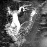
125 Only Long-T2 Tissues Have Signals CSF in spinal cord : long T2 tissue 125 of 214
")
 MIP")
126 Myelogram (Strongly T2-weighted FSE) Original slices (heavy T2 images) MIP 126 of 214

127 FSE MRCP (Same Principle) Original slices MIP MRCP 127 of 214

128 1-sec Fetal Scan Siemens 1.5 Tesla HASTE ETL = x240 Scan time = 1 sec 22 weeks gestation No artifacts from fetal motion 128 of 214

129 Including My Own Son 5-month photo Future look? 28-week gestation 35-week gestation Courtesy Cheng-Yu Chen, M.D., Tri-Service General Hospital 129 of 214
130 One Variation : HASTE Half-Fourier acquisition single-shot TurboSE (Siemens) Single-shot fast spin-echo (GE) Half Fourier + TSE = ~1s scan Reduce to ~130 0 for SAR 130 of 214
131 Multi-shot FSE Usage Almost the new standard for T2 Much faster than traditional SE HASTE best in GI Motion and susceptibility artifacts 131 of 214
132 FSE Advantages FSE similar to traditional SE Spin-echo already a standard FSE widely accepted as well No gradient-echo artifacts 132 of 214

 133 of 214")
133 Comparison between FSE T2 & SE T2 SE (TE = 100) TSE (TE = 100) 133 of 214
134 Speed Advantages Overcome motion artifacts Multiple signal averages for SNR in reasonable scan time Trade SNR for spatial resolution Long TR for proton density weighting 134 of 214

 135 of")
135 Speed Advantages in terms of Motion SE (ECG gating) FSE (no gating) 135 of 214

 136")
136 Speed Advantage in GI Imaging R-L frequency encoding 4:30 min scan, 512 matrix (readout) 136 of 214


137 Resolution Advantage with SNR 256x256, 57 sec 512x512, 2:45 min High-resolution in reasonable scan time 137 of 214

138 Long TR Advantage in Nerve Roots Siemens 1.5 Tesla Turbo Spin-echo 512 matrix 3 mm slice Scan time = 7 min Strong CSF & high resolution for nerve roots 138 of 214
139 FSE Properties Compared with SE at same TE Stronger magnetization transfer contrast Weaker diffusion weighting Bright fat at long ETL No time to explain in this semester 139 of 214
140 FSE Unique Artifacts Point-spread function blurring Will be briefly mentioned Pseudo edge enhancement Ghosts from data discontinuity No time to explain either 140 of 214
141 k-space Filling Pattern in FSE RF t k y G z t G y t k x G x t Signal t Early echo placed at central k-space : blurring 141 of 214

")
142 Blurring in FSE with Long ETL HASTE (176x256) HASTE (128x256) 142 of 214


143 ETL Comparison in Chest Imaging ETL 15 (ECG, BH, 14 sec) ETL 85 (0.4 sec) 143 of 214
144 Parallel MRI with RF Phased Array Coils Hsiao-Wen Chung ( 鍾孝文 ), Ph.D., Professor Dept. Electrical Engineering, National Taiwan Univ. Dept. Radiology, Tri-Service General Hospital 144 of 214
145 Review : Phased Array Surface coil: high SNR with limited coverage Phased array: multi coils with geometric arrangement to cancel mutual inductance Achieve high SNR and wide coverage simultaneously 145 of 214


146 Phased Array Coil 146 of 214

147 Spine Phased Array 147 of 214
148 Phased Array Image Formation Computer (reconstruction) Receiver Receiver Receiver Receiver Signals received and processed separately 148 of 214
149 Combine to Form Phased Array Image Wide FOV for larger coverage 149 of 214
150 Phased Array Imaging Coil elements receive signals separately Send to individual receiver channel No other difference at all RF pulsing, phase encoding, etc. 150 of 214
151 What Is Parallel Imaging? Signals in different coils must be different If data in different coils show little redundancy, can some steps be omitted? SMASH (1997),SENSE (1999) 151 of 214
152 Method 1 Produce various spatial frequency waveforms in k-space using the coil profiles Multiple k-space lines in one phase encoding 152 of 214
153 Review : k-space & MRI Each point in the k-space coordinate (kx,ky) coordinate : specific waveform Signal intensity : relative weighting of that waveform All MRIs are formed by these waveforms 153 of 214

154 A k-space point represents a waveform ky kx 154 of 214

155 Many waveforms summed to an MRI Waveforms weighed by signal intensity 155 of 214
156 Phased Array Helps in Signals received at various locations Adjust weights of signals according to the coil locations to form different waveforms from one single acquisition 156 of 214
157 Waveform Formation from Coil Profiles Coil arrangement Equal weights Form cosine Form sine High-freq cosine High-freq sine 8 elements arranged linearly 157 of 214
158 Many Waveforms from One Acquisition k y phase encoding k x freq encoding Many k-space lines from one phase encoding 158 of 214
159 Parallel Imaging Multiple k-space lines with one phase encoding due to separate signal receiving with phased array coils N waveforms N times acceleration 159 of 214
160 Let s Name It Many harmonics formed at once SiMultaneous Acquisition of Spatial Harmonics (SMASH) Sodickson of 214
161 Acceleration Factor Theoretically, N coil elements could form at most N harmonics Nothing is perfect in practice acceleration factor < N 161 of 214
162 SMASH Phantom Image (1997 MRM) Usual scan (10 sec) 3 coils (5 sec) 162 of 214
163 SMASH Body Image (1997 MRM) Usual scan (22 sec) 4 coils (11 sec) 163 of 214
 6 coils, R = 3 [Gd] = 0.")
164 SMASH CE-MRA (2000 Radiology) Philips ACS NT 1.5T FLASH, 7.0/1.5/30 0 3D (128px256x20) 6 coils, R = 3 [Gd] = 0.13 mm/kg 8 sec per 3D frame Shorten breath-hold time or high temporal resolution 164 of 214
165 SNR in SMASH Accelerate from reduced phase encoding SNR lowers according to the square root relationship Half scan time SNR lowered to 70% Used when reducing motion effects outweighs SNR loss 165 of 214
166 SMASH Pitfalls Coil size, shape, arrangement relatively restricted in order to form perfect sinusoids Direction of multi coils often not used for phase encoding 166 of 214

167 Waveform Formation from Coil Profiles Coil arrangement Equal weights Form cosine Form sine High-freq cosine High-freq sine 8 elements arranged linearly 167 of 214

168 Combine to Form Phased Array Image Head-foot direction is often freq encoding 168 of 214
169 Even Arrangement OK Sinusoids formed by coil profiles often non-perfect Imperfect reconstruction results in residual aliasing 169 of 214
 3 coils (5 sec) 170 of")
170 Aliasing in SMASH with R = 2 Usual scan (10 sec) 3 coils (5 sec) 170 of 214

 171")
171 Aliasing in SMASH with R = 2 Usual scan (22 sec) 4 coils (11 sec) 171 of 214
172 SMASH Extensions Auto-SMASH VD Auto-SMASH GRAPPA (Siemens) Details omitted 172 of 214
 173 of")
173 GRAPPA Lung Images HASTE 128x256 GRAPPA 256x256 Usual scan 207 ms 150 ms (8-coil array) 173 of 214
 174 of")
174 GRAPPA Liver Images HASTE 128x256 GRAPPA 256x256 Usual scan 252 ms 252 ms (8-coil array) 174 of 214
175 Method 2 Coils have different sensitivity profiles, all relatively small Reduce FOV for less phase encoding Accelerated, aliasing occurs Compute image according to the different aliasing patterns 175 of 214
176 3-coil Example Coil sensitivity profiles roughly occupy 1/3 FOV Prescribe a small FOV (~1/3) Resolution unchanged reduced matrix size 176 of 214
177 Example Using 3 Coils Phantom & coil locations 3 Aliased images 177 of 214
178 No Panic with Aliasing Aliased image = signals within FOV + outside FOV Signals stronger within coil profile, weaker outside weighted sum 178 of 214
179 Aliased Image from Coil 1 FOV aliasing 1 aliasing Phantom & coil location 179 of 214
 180 of")
180 Aliased Image from Coil 1 FOV aliasing (weaker) 1 Coil #1 local intensity aliasing (even weaker) 180 of 214
181 Aliased Image from Coil 1 aliasing (weaker) 1 Phantom & coil aliasing (even weaker) image 181 of 214
182 Aliased Image = Weighted Sum An aliased images (D1) = weighted sum of 3 sub-fov images In the form of D 1 = A 1 x + B 1 y + C 1 z 182 of 214
 image 183 of")
183 Aliased Image from Coil 2 aliasing (weaker) 2 Coil #2 local intensity aliasing (weaker) image 183 of 214
 Coil #3")
 image 184 of")
184 Aliased Image from Coil 3 aliasing (weaker) Coil #3 local intensity 3 aliasing (even weaker) image 184 of 214
185 3 Aliased Images from the 3 Coils Phantom & coil location 3 Aliased images 185 of 214
186 3 Aliased Images (D) D 1 = A 1 x + B 1 y + C 1 z D 2 = A 2 x + B 2 y + C 2 z D 3 = A 3 x + B 3 y + C 3 z Solving the equations (matrix inversion) gives (x, y, z) 186 of 214
187 Algebraic Problem Now 3 aliased images (D) in D = Ax + By + Cz form A, B, C: known from coil profiles Matrix inversion to get (x, y, z) 187 of 214
188 Don t Forget Each aliased pixel has one unique set of D = Ax + By + Cz equations Matrix inversion performed 256x256/3 times (for R = 3) 188 of 214
189 Summary 3 RF coils to receive signals 1/3 FOV prescribed with same resolution Scan accelerated 3 times from a reduction in matrix size (phase encoding) Full FOV image can be computed 189 of 214
190 3 Times Acceleration, Solve Equations Full FOV image obtained from aliased images 190 of 214
191 Let s Name It It is about the usage of coil sensitivity profiles SENSitivity Encoding (SENSE) Pruessmann 1999 Rumor has it that it s Philips patent 191 of 214
192 Acceleration Factor Theoretically, N coil elements provide at most N aliased images Smallest prescribed FOV is FOV/N Like SMASH, < N in reality 192 of 214
 2 coils (85 sec) 193 of")
193 SENSE Brain Image (1999 MRM) Usual scan (170 sec) 2 coils (85 sec) 193 of 214
 Usual")
 194")
194 SENSE Heart Image (Short Axis) Usual scan (15 beats) 5 coils (5 beats) 194 of 214
195 SNR in SENSE Acceleration thru reduced phase encoding SNR lowers according to square root relationship Like SMASH, Used when reducing motion effects outweighs SNR loss 195 of 214
 Usual scan")
 196 of 214")
196 SENSE Heart Image (Axial) Usual scan (128x128) 6 coils (R = 3) 196 of 214
197 SENSE Coil Requirement D 1 = A 1 x + B 1 y + C 1 z D 2 = A 2 x + B 2 y + C 2 z D 3 = A 3 x + B 3 y + C 3 z Solvable as long as equations are linearly independent 197 of 214

198 SENSE RF Coil Arrangement Phase RF coil element Phase Phase direction can be either one 198 of 214
199 SENSE Coil Requirement Linearly independent equations No need to form perfect sinusoid Easier than SMASH No many variations like GRAPPA 199 of 214
200 SENSE Pitfalls Incompatible with restricted FOV Example : cardiac imaging Full FOV contains some aliasing Can t distinguish after mixture with 1/3 FOV aliasing 200 of 214
201 Theoretical Comparison SMASH : Fast computation (Fourier transform) Artifact performance better than SENSE at high acceleration factors 201 of 214
202 Theoretical Comparison SENSE : Coil arrangement flexible Flexible slice orientation as in MRI General artifacts less than SMASH 202 of 214
203 Practical Comparison SENSE & SMASH performance highly depends on human resources devoted to R&D No major difference when commercialized 203 of 214
204 Parallel Imaging Families Philips : SENSE Siemens : ipat GRAPPA + msense General Electric : ASSET 204 of 214
205 Parallel MRI Advantages Phased array coils have long been commercialized ( 94) Matrix inversion software simple Acceleration is basically pulsesequence independent 205 of 214

 Similar")
206 SENSE Coronary Angiogram Usual scan (3.0 T) Similar quality at 3x 206 of 214


207 Speed Advantage of SENSE Abdominal CE-MRA 512x512 T2W FSE 207 of 214
208 More Advantages Shorten EPI acquisition time Less EPI geometric distortion Reduce ETL in FSE Less blurring in HASTE 208 of 214


209 SMASH EPI of Brain (Sagittal) Usual scan Four coils 209 of 214
 to reduce distortions (3.0T) 210 of 214")
210 SENSE DW-EPI of Brain (Axial) 8 coils (R = 4) to reduce distortions (3.0T) 210 of 214

211 SMASH HASTE of Chest (192x256) Usual scan Four coils 211 of 214

212 Trade Scan Time for Resolution (R = 2) Usual scan 192x256, 450 ms 4 coils 192x256, 225 ms 4 coils 384x256, 450 ms 212 of 214
213 Parallel MRI Advantages Major medical centers will have it soon after its first introduction Taiwan will have it after 3-5 years at the latest time (a matter of $$) 213 of 214
214 The Fast Imaging Techniques Hsiao-Wen Chung ( 鍾孝文 ), Ph.D., Professor Dept. Electrical Engineering, National Taiwan Univ. Dept. Radiology, Tri-Service General Hospital 214 of 214
MRI. When to use What sequences. Outline 2012/09/19. Sequence: Definition. Basic Principles: Step 2. Basic Principles: Step 1. Govind Chavhan, MD
 MRI When to use What sequences Govind Chavhan, MD Assistant Professor and Staff Radiologist The Hospital For Sick Children, Toronto Planning Acquisition Post processing Interpretation Patient history and
M R I Physics Course
 M R I Physics Course Multichannel Technology & Parallel Imaging Nathan Yanasak, Ph.D. Jerry Allison Ph.D. Tom Lavin, B.S. Department of Radiology Medical College of Georgia References: 1) The Physics of
Parallel Imaging. Marcin.
 Parallel Imaging Marcin m.jankiewicz@gmail.com Parallel Imaging initial thoughts Over the last 15 years, great progress in the development of pmri methods has taken place, thereby producing a multitude
MRI Physics II: Gradients, Imaging
 MRI Physics II: Gradients, Imaging Douglas C., Ph.D. Dept. of Biomedical Engineering University of Michigan, Ann Arbor Magnetic Fields in MRI B 0 The main magnetic field. Always on (0.5-7 T) Magnetizes
Lab Location: MRI, B2, Cardinal Carter Wing, St. Michael s Hospital, 30 Bond Street
 Lab Location: MRI, B2, Cardinal Carter Wing, St. Michael s Hospital, 30 Bond Street MRI is located in the sub basement of CC wing. From Queen or Victoria, follow the baby blue arrows and ride the CC south
HST.583 Functional Magnetic Resonance Imaging: Data Acquisition and Analysis Fall 2008
 MIT OpenCourseWare http://ocw.mit.edu HST.583 Functional Magnetic Resonance Imaging: Data Acquisition and Analysis Fall 2008 For information about citing these materials or our Terms of Use, visit: http://ocw.mit.edu/terms.
Clinical Importance. Aortic Stenosis. Aortic Regurgitation. Ultrasound vs. MRI. Carotid Artery Stenosis
 Clinical Importance Rapid cardiovascular flow quantitation using sliceselective Fourier velocity encoding with spiral readouts Valve disease affects 10% of patients with heart disease in the U.S. Most
Module 4. K-Space Symmetry. Review. K-Space Review. K-Space Symmetry. Partial or Fractional Echo. Half or Partial Fourier HASTE
 MRES 7005 - Fast Imaging Techniques Module 4 K-Space Symmetry Review K-Space Review K-Space Symmetry Partial or Fractional Echo Half or Partial Fourier HASTE Conditions for successful reconstruction Interpolation
HST.583 Functional Magnetic Resonance Imaging: Data Acquisition and Analysis Fall 2006
 MIT OpenCourseWare http://ocw.mit.edu HST.583 Functional Magnetic Resonance Imaging: Data Acquisition and Analysis Fall 2006 For information about citing these materials or our Terms of Use, visit: http://ocw.mit.edu/terms.
Fast Imaging UCLA. Class Business. Class Business. Daniel B. Ennis, Ph.D. Magnetic Resonance Research Labs. Tuesday (3/7) from 6-9pm HW #1 HW #2
 from 6-9pm HW #1 HW #2") Fast Imaging Daniel B. Ennis, Ph.D. Magnetic Resonance Research Labs Class Business Tuesday (3/7) from 6-9pm 6:00-7:30pm Groups Avanto Sara Said, Yara Azar, April Pan Skyra Timothy Marcum, Diana Lopez,
Fast Imaging Daniel B. Ennis, Ph.D. Magnetic Resonance Research Labs Class Business Tuesday (3/7) from 6-9pm 6:00-7:30pm Groups Avanto Sara Said, Yara Azar, April Pan Skyra Timothy Marcum, Diana Lopez,
Parallel Magnetic Resonance Imaging (pmri): How Does it Work, and What is it Good For?
: How Does it Work, and What is it Good For?") Parallel Magnetic Resonance Imaging (pmri): How Does it Work, and What is it Good For? Nathan Yanasak, Ph.D. Chair, AAPM TG118 Department of Radiology Georgia Regents University Overview Phased-array coils
Parallel Magnetic Resonance Imaging (pmri): How Does it Work, and What is it Good For? Nathan Yanasak, Ph.D. Chair, AAPM TG118 Department of Radiology Georgia Regents University Overview Phased-array coils
(a Scrhon5 R2iwd b. P)jc%z 5. ivcr3. 1. I. ZOms Xn,s. 1E IDrAS boms. EE225E/BIOE265 Spring 2013 Principles of MRI. Assignment 8 Solutions
jc%z 5. ivcr3. 1. I. ZOms Xn,s. 1E IDrAS boms. EE225E/BIOE265 Spring 2013 Principles of MRI. Assignment 8 Solutions") EE225E/BIOE265 Spring 2013 Principles of MRI Miki Lustig Assignment 8 Solutions 1. Nishimura 7.1 P)jc%z 5 ivcr3. 1. I Due Wednesday April 10th, 2013 (a Scrhon5 R2iwd b 0 ZOms Xn,s r cx > qs 4-4 8ni6 4
EE225E/BIOE265 Spring 2013 Principles of MRI Miki Lustig Assignment 8 Solutions 1. Nishimura 7.1 P)jc%z 5 ivcr3. 1. I Due Wednesday April 10th, 2013 (a Scrhon5 R2iwd b 0 ZOms Xn,s r cx > qs 4-4 8ni6 4
New Technology Allows Multiple Image Contrasts in a Single Scan
 These images were acquired with an investigational device. PD T2 T2 FLAIR T1 MAP T1 FLAIR PSIR T1 New Technology Allows Multiple Image Contrasts in a Single Scan MR exams can be time consuming. A typical
HST.583 Functional Magnetic Resonance Imaging: Data Acquisition and Analysis Fall 2008
 MIT OpenCourseWare http://ocw.mit.edu HST.583 Functional Magnetic Resonance Imaging: Data Acquisition and Analysis Fall 2008 For information about citing these materials or our Terms of Use, visit: http://ocw.mit.edu/terms.
Accelerated MRI Techniques: Basics of Parallel Imaging and Compressed Sensing
 Accelerated MRI Techniques: Basics of Parallel Imaging and Compressed Sensing Peng Hu, Ph.D. Associate Professor Department of Radiological Sciences PengHu@mednet.ucla.edu 310-267-6838 MRI... MRI has low
Diffusion MRI Acquisition. Karla Miller FMRIB Centre, University of Oxford
 Diffusion MRI Acquisition Karla Miller FMRIB Centre, University of Oxford karla@fmrib.ox.ac.uk Diffusion Imaging How is diffusion weighting achieved? How is the image acquired? What are the limitations,
Orthopedic MRI Protocols. Philips Panorama HFO
 Orthopedic MRI Protocols Philips Panorama HFO 1 2 Prepared in collaboration with Dr. John F. Feller, Medical Director of Desert Medical Imaging, Palm Springs, CA. Desert Medical Imaging will provide the
What is pmri? Overview. The Need for Speed: A Technical and Clinical Primer for Parallel MR Imaging 8/1/2011
 The Need for Speed: A Technical and Clinical Primer for Parallel MR Imaging Nathan Yanasak, Ph.D. Chair, AAPM TG118 Assistant Professor Department of Radiology Director, Core Imaging Facility for Small
White Pixel Artifact. Caused by a noise spike during acquisition Spike in K-space <--> sinusoid in image space
 White Pixel Artifact Caused by a noise spike during acquisition Spike in K-space sinusoid in image space Susceptibility Artifacts Off-resonance artifacts caused by adjacent regions with different
COBRE Scan Information
 COBRE Scan Information Below is more information on the directory structure for the COBRE imaging data. Also below are the imaging parameters for each series. Directory structure: var/www/html/dropbox/1139_anonymized/human:
Module 5: Dynamic Imaging and Phase Sharing. (true-fisp, TRICKS, CAPR, DISTAL, DISCO, HYPR) Review. Improving Temporal Resolution.
 Review. Improving Temporal Resolution.") MRES 7005 - Fast Imaging Techniques Module 5: Dynamic Imaging and Phase Sharing (true-fisp, TRICKS, CAPR, DISTAL, DISCO, HYPR) Review Improving Temporal Resolution True-FISP (I) True-FISP (II) Keyhole
MRES 7005 - Fast Imaging Techniques Module 5: Dynamic Imaging and Phase Sharing (true-fisp, TRICKS, CAPR, DISTAL, DISCO, HYPR) Review Improving Temporal Resolution True-FISP (I) True-FISP (II) Keyhole
CHAPTER 9: Magnetic Susceptibility Effects in High Field MRI
 Figure 1. In the brain, the gray matter has substantially more blood vessels and capillaries than white matter. The magnified image on the right displays the rich vasculature in gray matter forming porous,
A Virtual MR Scanner for Education
 A Virtual MR Scanner for Education Hackländer T, Schalla C, Trümper A, Mertens H, Hiltner J, Cramer BM Hospitals of the University Witten/Herdecke, Department of Radiology Wuppertal, Germany Purpose A
Role of Parallel Imaging in High Field Functional MRI
 Role of Parallel Imaging in High Field Functional MRI Douglas C. Noll & Bradley P. Sutton Department of Biomedical Engineering, University of Michigan Supported by NIH Grant DA15410 & The Whitaker Foundation
SIEMENS MAGNETOM Avanto syngo MR B15
 \\USER\INVESTIGATORS\Ravi\ADNI-Subject\Localizer TA: 0:10 PAT: Voxel size: 1.9 1.5 8.0 mm Rel. SNR: 1.00 SIEMENS: gre Properties Prio Recon Before measurement After measurement Load to viewer Inline movie
MR Advance Techniques. Vascular Imaging. Class III
 MR Advance Techniques Vascular Imaging Class III 1 Vascular Imaging There are several methods that can be used to evaluate the cardiovascular systems with the use of MRI. MRI will aloud to evaluate morphology
Slide 1. Technical Aspects of Quality Control in Magnetic Resonance Imaging. Slide 2. Annual Compliance Testing. of MRI Systems.
 Slide 1 Technical Aspects of Quality Control in Magnetic Resonance Imaging Slide 2 Compliance Testing of MRI Systems, Ph.D. Department of Radiology Henry Ford Hospital, Detroit, MI Slide 3 Compliance Testing
Dynamic Contrast enhanced MRA
 Dynamic Contrast enhanced MRA Speaker: Yung-Chieh Chang Date : 106.07.22 Department of Radiology, Taichung Veterans General Hospital, Taichung, Taiwan 1 Outline Basic and advanced principles of Diffusion
XI Signal-to-Noise (SNR)
") XI Signal-to-Noise (SNR) Lecture notes by Assaf Tal n(t) t. Noise. Characterizing Noise Noise is a random signal that gets added to all of our measurements. In D it looks like this: while in D
XI Signal-to-Noise (SNR) Lecture notes by Assaf Tal n(t) t. Noise. Characterizing Noise Noise is a random signal that gets added to all of our measurements. In D it looks like this: while in D
Classification of Subject Motion for Improved Reconstruction of Dynamic Magnetic Resonance Imaging
 1 CS 9 Final Project Classification of Subject Motion for Improved Reconstruction of Dynamic Magnetic Resonance Imaging Feiyu Chen Department of Electrical Engineering ABSTRACT Subject motion is a significant
Midterm Review
 Midterm Review - 2017 EE369B Concepts Noise Simulations with Bloch Matrices, EPG Gradient Echo Imaging 1 About the Midterm Monday Oct 30, 2017. CCSR 4107 Up to end of C2 1. Write your name legibly on this
Functional MRI. Jerry Allison, Ph. D. Medical College of Georgia
 Functional MRI Jerry Allison, Ph. D. Medical College of Georgia BOLD Imaging Technique Blood Oxygen Level Dependent contrast can be used to map brain function Right Hand Motor Task Outline fmri BOLD Contrast
A Novel Iterative Thresholding Algorithm for Compressed Sensing Reconstruction of Quantitative MRI Parameters from Insufficient Data
 A Novel Iterative Thresholding Algorithm for Compressed Sensing Reconstruction of Quantitative MRI Parameters from Insufficient Data Alexey Samsonov, Julia Velikina Departments of Radiology and Medical
Sparse sampling in MRI: From basic theory to clinical application. R. Marc Lebel, PhD Department of Electrical Engineering Department of Radiology
 Sparse sampling in MRI: From basic theory to clinical application R. Marc Lebel, PhD Department of Electrical Engineering Department of Radiology Objective Provide an intuitive overview of compressed sensing
Exam 8N080 - Introduction MRI
 Exam 8N080 - Introduction MRI Friday January 23 rd 2015, 13.30-16.30h For this exam you may use an ordinary calculator (not a graphical one). In total there are 6 assignments and a total of 65 points can
8/11/2009. Common Areas of Motion Problem. Motion Compensation Techniques and Applications. Type of Motion. What s your problem
 Common Areas of Motion Problem Motion Compensation Techniques and Applications Abdominal and cardiac imaging. Uncooperative patient, such as pediatric. Dynamic imaging and time series. Chen Lin, PhD Indiana
Compressed Sensing for Rapid MR Imaging
 Compressed Sensing for Rapid Imaging Michael Lustig1, Juan Santos1, David Donoho2 and John Pauly1 1 Electrical Engineering Department, Stanford University 2 Statistics Department, Stanford University rapid
Motion Artifacts and Suppression in MRI At a Glance
 Motion Artifacts and Suppression in MRI At a Glance Xiaodong Zhong, PhD MR R&D Collaborations Siemens Healthcare MRI Motion Artifacts and Suppression At a Glance Outline Background Physics Common Motion
SIEMENS MAGNETOM Avanto syngo MR B15
 \\USER\INVESTIGATORS\Ravi\ADNI-phantom\QC Phantom-Localizer TA: 0:10 PAT: Voxel size: 1.9 1.5 8.0 mm Rel. SNR: 1.00 SIEMENS: gre Properties Prio Recon Before measurement After measurement Load to viewer
Outline: Contrast-enhanced MRA
 Outline: Contrast-enhanced MRA Background Technique Clinical Indications Future Directions Disclosures: GE Health Care: Research support Consultant: Bracco, Bayer The Basics During rapid IV infusion, Gadolinium
surface Image reconstruction: 2D Fourier Transform
 2/1/217 Chapter 2-3 K-space Intro to k-space sampling (chap 3) Frequenc encoding and Discrete sampling (chap 2) Point Spread Function K-space properties K-space sampling principles (chap 3) Basic Contrast
MRI Imaging Options. Frank R. Korosec, Ph.D. Departments of Radiology and Medical Physics University of Wisconsin Madison
 MRI Imaging Options Frank R. Korosec, Ph.D. Departments of Radiolog and Medical Phsics Universit of Wisconsin Madison f.korosec@hosp.wisc.edu As MR imaging becomes more developed, more imaging options
Dynamic Autocalibrated Parallel Imaging Using Temporal GRAPPA (TGRAPPA)
") Magnetic Resonance in Medicine 53:981 985 (2005) Dynamic Autocalibrated Parallel Imaging Using Temporal GRAPPA (TGRAPPA) Felix A. Breuer, 1 * Peter Kellman, 2 Mark A. Griswold, 1 and Peter M. Jakob 1 Current
Magnetic Resonance in Medicine 53:981 985 (2005) Dynamic Autocalibrated Parallel Imaging Using Temporal GRAPPA (TGRAPPA) Felix A. Breuer, 1 * Peter Kellman, 2 Mark A. Griswold, 1 and Peter M. Jakob 1 Current
MRI image formation 8/3/2016. Disclosure. Outlines. Chen Lin, PhD DABR 3. Indiana University School of Medicine and Indiana University Health
 MRI image formation Indiana University School of Medicine and Indiana University Health Disclosure No conflict of interest for this presentation 2 Outlines Data acquisition Spatial (Slice/Slab) selection
Fmri Spatial Processing
 Educational Course: Fmri Spatial Processing Ray Razlighi Jun. 8, 2014 Spatial Processing Spatial Re-alignment Geometric distortion correction Spatial Normalization Smoothing Why, When, How, Which Why is
Gradient-Echo. Spin-Echo. Echo planar. Assessment of Regional Function Assessment of Global. Parallel Imaging. Function. Steady State Imaging
 Gradient-Echo Spin-Echo James W. Goldfarb Ph.D. Department of Research and Education St. Francis Hospital Program in Biomedical Engineering SUNY Stony Brook Echo planar Assessment of Regional Function
Fast Imaging Trajectories: Non-Cartesian Sampling (1)
") Fast Imaging Trajectories: Non-Cartesian Sampling (1) M229 Advanced Topics in MRI Holden H. Wu, Ph.D. 2018.05.03 Department of Radiological Sciences David Geffen School of Medicine at UCLA Class Business
Fast Imaging Trajectories: Non-Cartesian Sampling (1) M229 Advanced Topics in MRI Holden H. Wu, Ph.D. 2018.05.03 Department of Radiological Sciences David Geffen School of Medicine at UCLA Class Business
Release Notes. Multi-Band EPI C2P. Release HCP_v1 10 February 2014
 Release Notes Multi-Band EPI C2P Release HCP_v1 10 February 2014 Installation 1. Restart the system (reboot host and MRIR) 2. Extract the.zip file to a temporary directory 3. Run the installer.bat file
Sampling, Ordering, Interleaving
 Sampling, Ordering, Interleaving Sampling patterns and PSFs View ordering Modulation due to transients Temporal modulations Slice interleaving Sequential, Odd/even, bit-reversed Arbitrary Other considerations:
Imaging Notes, Part IV
 BME 483 MRI Notes 34 page 1 Imaging Notes, Part IV Slice Selective Excitation The most common approach for dealing with the 3 rd (z) dimension is to use slice selective excitation. This is done by applying
UNIVERSITY OF SOUTHAMPTON
 UNIVERSITY OF SOUTHAMPTON PHYS2007W1 SEMESTER 2 EXAMINATION 2014-2015 MEDICAL PHYSICS Duration: 120 MINS (2 hours) This paper contains 10 questions. Answer all questions in Section A and only two questions
Abbie M. Diak, PhD Loyola University Medical Center Dept. of Radiation Oncology
 Abbie M. Diak, PhD Loyola University Medical Center Dept. of Radiation Oncology Outline High Spectral and Spatial Resolution MR Imaging (HiSS) What it is How to do it Ways to use it HiSS for Radiation
Supplementary methods
 Supplementary methods This section provides additional technical details on the sample, the applied imaging and analysis steps and methods. Structural imaging Trained radiographers placed all participants
GE Healthcare CLINICAL GALLERY. Discovery * MR750w 3.0T. This brochure is intended for European healthcare professionals.
 GE Healthcare CLINICAL GALLERY Discovery * MR750w 3.0T This brochure is intended for European healthcare professionals. NEURO PROPELLER delivers high resolution, motion insensitive imaging in all planes.
Page 1 of 9. Protocol: adult_other_adni3basichumanprotocol25x_ _ _1. 3 Plane Localizer. 3 Plane Localizer PATIENT POSITION
 3 Localizer FOV 26.0 Slice Thickness 5.0 Slice Spacing 0.0 Freq 256 Phase 128 3-PLANE 3 Localizer Unswap Phase Correction Gradient Echo Imaging Options Seq, Fast Recon All Images 3 Localizer Pause / SCIC
Basic fmri Design and Analysis. Preprocessing
 Basic fmri Design and Analysis Preprocessing fmri Preprocessing Slice timing correction Geometric distortion correction Head motion correction Temporal filtering Intensity normalization Spatial filtering
ADNI, ADNI_QH, SURVEY. Geometry. connection
 ADNI, ADNI_QH, SURVEY Geometry Coil selection = Head connection = d Multi coil Homogeneity correction ne FOV (mm) = 250.00 RFOV (%) = 100.00 Foldover suppression Matrix scan = 256 reconstruction = 256
BME I5000: Biomedical Imaging
 1 Lucas Parra, CCNY BME I5000: Biomedical Imaging Lecture 4 Computed Tomography Lucas C. Parra, parra@ccny.cuny.edu some slides inspired by lecture notes of Andreas H. Hilscher at Columbia University.
SIEMENS MAGNETOM Skyra syngo MR D13
 Page 1 of 8 SIEMENS MAGNETOM Skyra syngo MR D13 \\USER\CIND\StudyProtocols\PTSA\*dm_ep2d_mono70_b0_p2_iso2.0 TA:1:05 PAT:2 Voxel size:2.0 2.0 2.0 mm Rel. SNR:1.00 :epse Properties Routine Prio Recon Load
SPM8 for Basic and Clinical Investigators. Preprocessing. fmri Preprocessing
 SPM8 for Basic and Clinical Investigators Preprocessing fmri Preprocessing Slice timing correction Geometric distortion correction Head motion correction Temporal filtering Intensity normalization Spatial
University of Cape Town
 Development of a 3D radial MR Imaging sequence to be used for (self) navigation during the scanning of the fetal brain in utero by Leah Morgan Thesis presented for the degree of Master of Science June
SIEMENS MAGNETOM Verio syngo MR B15V
 \\USER\ZAHID_RESEARCH\MS\No Name\3D SWI TA: 6:39 PAT: 2 Voxel size: 1.0 0.5 2.0 mm Rel. SNR: 1.00 SIEMENS: gre Properties Prio Recon Before measurement After measurement Load to viewer Inline movie Auto
Philips MRI Protocol Dump Created on Comment Software Stream
 Page 1 of 5 Philips MRI Protocol Dump Created on 2/17/2011 4:11:01 PM Comment Created by ExamCard_to_XML with inputs: "J:\ADNI GO - ADNI 2 Phantom5.ExamCard" on system (BU SCHOOL OF MEDICINE :: 192.168.71.10)
Functional MRI in Clinical Research and Practice Preprocessing
 Functional MRI in Clinical Research and Practice Preprocessing fmri Preprocessing Slice timing correction Geometric distortion correction Head motion correction Temporal filtering Intensity normalization
Sampling, Ordering, Interleaving
 Sampling, Ordering, Interleaving Sampling patterns and PSFs View ordering Modulation due to transients Temporal modulations Timing: cine, gating, triggering Slice interleaving Sequential, Odd/even, bit-reversed
G Practical Magnetic Resonance Imaging II Sackler Institute of Biomedical Sciences New York University School of Medicine. Compressed Sensing
 G16.4428 Practical Magnetic Resonance Imaging II Sackler Institute of Biomedical Sciences New York University School of Medicine Compressed Sensing Ricardo Otazo, PhD ricardo.otazo@nyumc.org Compressed
Evaluations of k-space Trajectories for Fast MR Imaging for project of the course EE591, Fall 2004
 Evaluations of k-space Trajectories for Fast MR Imaging for project of the course EE591, Fall 24 1 Alec Chi-Wah Wong Department of Electrical Engineering University of Southern California 374 McClintock
Magnetic Resonance Angiography
 Magnetic Resonance Angiography Course: Advance MRI (BIOE 594) Instructors: Dr Xiaohong Joe Zhou Dr. Shadi Othman By, Nayan Pasad Phase Contrast Angiography By Moran 1982, Bryan et. Al. 1984 and Moran et.
SIEMENS MAGNETOM Verio syngo MR B17
 \\USER\Dr. Behrmann\routine\Ilan\ep2d_bold_PMU_resting TA: 8:06 PAT: Voxel size: 3.03.03.0 mm Rel. SNR: 1.00 USER: ep2d_bold_pmu Properties Special sat. Prio Recon System Before measurement Body After
Qualitative Comparison of Conventional and Oblique MRI for Detection of Herniated Spinal Discs
 Qualitative Comparison of Conventional and Oblique MRI for Detection of Herniated Spinal Discs Doug Dean Final Project Presentation ENGN 2500: Medical Image Analysis May 16, 2011 Outline Review of the
T 1 MAPPING FOR DCE-MRI
 T 1 MAPPING FOR DCE-MRI A dissertation submitted to the Faculty of Medicine, University of Malaya in partial fulfillment of the requirements for the degree of Master of Medical Physics By NURUN NAJWA BINTI
EPI Data Are Acquired Serially. EPI Data Are Acquired Serially 10/23/2011. Functional Connectivity Preprocessing. fmri Preprocessing
 Functional Connectivity Preprocessing Geometric distortion Head motion Geometric distortion Head motion EPI Data Are Acquired Serially EPI Data Are Acquired Serially descending 1 EPI Data Are Acquired
SPM8 for Basic and Clinical Investigators. Preprocessing
 SPM8 for Basic and Clinical Investigators Preprocessing fmri Preprocessing Slice timing correction Geometric distortion correction Head motion correction Temporal filtering Intensity normalization Spatial
Use of MRI in Radiotherapy: Technical Consideration
 Use of MRI in Radiotherapy: Technical Consideration Yanle Hu, PhD Department of Radiation Oncology, Mayo Clinic Arizona 04/07/2018 2015 MFMER slide-1 Conflict of Interest: None 2015 MFMER slide-2 Objectives
MB-EPI PCASL. Release Notes for Version February 2015
 MB-EPI PCASL Release Notes for Version 1.0 20 February 2015 1 Background High-resolution arterial spin labeling (ASL) imaging is highly desirable in both neuroscience research and clinical applications
Applications Guide for Interleaved
 Applications Guide for Interleaved rephase/dephase MRAV Authors: Yongquan Ye, Ph.D. Dongmei Wu, MS. Tested MAGNETOM Systems : 7TZ, TRIO a Tim System, Verio MR B15A (N4_VB15A_LATEST_20070519) MR B17A (N4_VB17A_LATEST_20090307_P8)
Computational Medical Imaging Analysis
 Computational Medical Imaging Analysis Chapter 2: Image Acquisition Systems Jun Zhang Laboratory for Computational Medical Imaging & Data Analysis Department of Computer Science University of Kentucky
Lucy Phantom MR Grid Evaluation
 Lucy Phantom MR Grid Evaluation Anil Sethi, PhD Loyola University Medical Center, Maywood, IL 60153 November 2015 I. Introduction: The MR distortion grid, used as an insert with Lucy 3D QA phantom, is
Single Breath-hold Abdominal T 1 Mapping using 3-D Cartesian Sampling and Spatiotemporally Constrained Reconstruction
 Single Breath-hold Abdominal T 1 Mapping using 3-D Cartesian Sampling and Spatiotemporally Constrained Reconstruction Felix Lugauer 1,3, Jens Wetzl 1, Christoph Forman 2, Manuel Schneider 1, Berthold Kiefer
Breast MRI Accreditation Program Clinical Image Quality Guide
 Breast MRI Accreditation Program Clinical Image Quality Guide Introduction This document provides guidance on breast MRI clinical image quality and describes the criteria used by the ACR Breast MRI Accreditation
Siemens AG, Healthcare Sector. syngo MR D13 0. Supplement - Parameters and image text 0.
 Siemens AG, Healthcare Sector 0 0 n.a. English Cs2 syngo Neuro Operator MR-05014 630 05/2010 01 02 Informatik, Manual D11 Cape syngo MR D13 0.0 Supplement - Parameters and image text 0. syngo MR D13 0.
Steen Moeller Center for Magnetic Resonance research University of Minnesota
 Steen Moeller Center for Magnetic Resonance research University of Minnesota moeller@cmrr.umn.edu Lot of material is from a talk by Douglas C. Noll Department of Biomedical Engineering Functional MRI Laboratory
MRI Hot Topics Motion Correction for MR Imaging. medical
 MRI Hot Topics Motion Correction for MR Imaging s medical Motion Correction for MR Imaging Kyle A. Salem, PhD Motion Artifacts in a Clinical Setting Patient motion is probably the most common cause of
The SIMRI project A versatile and interactive MRI simulator *
 COST B21 Meeting, Lodz, 6-9 Oct. 2005 The SIMRI project A versatile and interactive MRI simulator * H. Benoit-Cattin 1, G. Collewet 2, B. Belaroussi 1, H. Saint-Jalmes 3, C. Odet 1 1 CREATIS, UMR CNRS
This Time. fmri Data analysis
 This Time Reslice example Spatial Normalization Noise in fmri Methods for estimating and correcting for physiologic noise SPM Example Spatial Normalization: Remind ourselves what a typical functional image
SIEMENS MAGNETOM TrioTim syngo MR B17
 \\USER\KNARRGROUP\MultiBand\LavretskyMultiBand\trufi localizer 3-plane TA: 5.1 s PAT: Voxel size: 1.2 1.2 5. Rel. SNR: 1.00 SIEMENS: trufi Load to stamp Slice group 1 Slices 1 Dist. factor 20 % Phase enc.
Acquisition Methods for fmri at 7 Tesla
 Acquisition Methods for fmri at 7 Tesla Peter J. Koopmans, Nuffield department for clinical neurosciences, University of Oxford, UK fmri at 7 Tesla is mostly used in the context of high spatial resolution
An Introduction to Image Reconstruction, Processing, and their Effects in FMRI
 An Introduction to Image Reconstruction, Processing, and their Effects in FMRI Daniel B. Rowe Program in Computational Sciences Department of Mathematics, Statistics, and Computer Science Marquette University
Improved Spatial Localization in 3D MRSI with a Sequence Combining PSF-Choice, EPSI and a Resolution Enhancement Algorithm
 Improved Spatial Localization in 3D MRSI with a Sequence Combining PSF-Choice, EPSI and a Resolution Enhancement Algorithm L.P. Panych 1,3, B. Madore 1,3, W.S. Hoge 1,3, R.V. Mulkern 2,3 1 Brigham and
Generalized Autocalibrating Partially Parallel Acquisitions (GRAPPA)
") Magnetic Resonance in Medicine 47:1202 1210 (2002) Generalized Autocalibrating Partially Parallel Acquisitions (GRAPPA) Mark A. Griswold, 1 * Peter M. Jakob, 1 Robin M. Heidemann, 1 Mathias Nittka, 2 Vladimir
Magnetic Resonance in Medicine 47:1202 1210 (2002) Generalized Autocalibrating Partially Parallel Acquisitions (GRAPPA) Mark A. Griswold, 1 * Peter M. Jakob, 1 Robin M. Heidemann, 1 Mathias Nittka, 2 Vladimir
Head motion in diffusion MRI
 Head motion in diffusion MRI Anastasia Yendiki HMS/MGH/MIT Athinoula A. Martinos Center for Biomedical Imaging 11/06/13 Head motion in diffusion MRI 0/33 Diffusion contrast Basic principle of diffusion
Chapter 3 Set Redundancy in Magnetic Resonance Brain Images
 16 Chapter 3 Set Redundancy in Magnetic Resonance Brain Images 3.1 MRI (magnetic resonance imaging) MRI is a technique of measuring physical structure within the human anatomy. Our proposed research focuses
design as a constrained maximization problem. In principle, CODE seeks to maximize the b-value, defined as, where
 Optimal design of motion-compensated diffusion gradient waveforms Óscar Peña-Nogales 1, Rodrigo de Luis-Garcia 1, Santiago Aja-Fernández 1,Yuxin Zhang 2,3, James H. Holmes 2,Diego Hernando 2,3 1 Laboratorio
Removal of EPI Nyquist Ghost Artifacts With Two- Dimensional Phase Correction
 Removal of EPI Nyquist Ghost Artifacts With Two- Dimensional Phase Correction Nan-kuei Chen 1,5 and Alice M. Wyrwicz 4 * Magnetic Resonance in Medicine 51:147 153 (004) Odd even echo inconsistencies result
SIEMENS MAGNETOM Symphony syngo MR A30
 \\USER\ADNI STUDY\MAIN PROTOCOL\HUMAN PROTOCOL\localizer Scan Time: 9.2 [s] Voxel size: 2.2 1.1 10.0 [mm] Rel. SNR: 1.00 SIEMENS: gre Slice group 1 Slice group 2 Slice group 3 280 [mm] 10 [mm] 20 [ms]
Correction for EPI Distortions Using Multi-Echo Gradient-Echo Imaging
 Correction for EPI Distortions Using Multi-Echo Gradient-Echo Imaging Nan-kuei Chen and Alice M. Wyrwicz* Magnetic Resonance in Medicine 41:1206 1213 (1999) A novel and effective technique is described
Enhao Gong, PhD Candidate, Electrical Engineering, Stanford University Dr. John Pauly, Professor in Electrical Engineering, Stanford University Dr.
 Enhao Gong, PhD Candidate, Electrical Engineering, Stanford University Dr. John Pauly, Professor in Electrical Engineering, Stanford University Dr. Greg Zaharchuk, Associate Professor in Radiology, Stanford
Field Maps. 1 Field Map Acquisition. John Pauly. October 5, 2005
 Field Maps John Pauly October 5, 25 The acquisition and reconstruction of frequency, or field, maps is important for both the acquisition of MRI data, and for its reconstruction. Many of the imaging methods
Analysis of Functional MRI Timeseries Data Using Signal Processing Techniques
 Analysis of Functional MRI Timeseries Data Using Signal Processing Techniques Sea Chen Department of Biomedical Engineering Advisors: Dr. Charles A. Bouman and Dr. Mark J. Lowe S. Chen Final Exam October
Super-resolution Reconstruction of Fetal Brain MRI
 Super-resolution Reconstruction of Fetal Brain MRI Ali Gholipour and Simon K. Warfield Computational Radiology Laboratory Children s Hospital Boston, Harvard Medical School Worshop on Image Analysis for