Topology Optimization for Designers
|
|
|
- Osborn White
- 6 years ago
- Views:
Transcription

1 TM Topology Optimization for Designers Siemens AG 2016 Realize innovation.
2 Topology Optimization for Designers Product Features Uses a different approach than traditional Topology Optimization solutions. Works in the NX CAD Work part in the context of an assembly. Meshless (to the user) Model definition uses the designs Functional Requirements, eg: Keep in/out volumes. Cylindrical holes with offset material around the hole. Counter bore holes with space for screw head, nut, socket wrench etc. Manufacturing constraints. FE loads & constraints. Level of resolution control. Max stiffness objective with a Mass constraint. Quick Topology Optimization solution. Highly smoothed, organic shapes with sharp edges where required.


3 Downstream 1. Direct to AM printing. 2. Direct use using Convergent models Convergent model is a new Parasolid format introduced in NX 11. Single data format for both/either NURBS and Facet geometry. Existing modeling functionality will work on both in the same CAD body. Start with faceted body add NURBS geometry, fillet between them. Limited support in NX 11. Only Facet Convergent bodies, boolean join, subtract & intersect. 3. Guidance for re-modeling using traditional CAD tools. Holes cut into Convergent Facet model

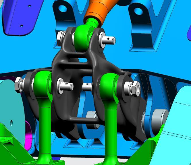
4 Topology Optimization in the Assembly Context Works in the NX CAD Work part in the context of an assembly. Enables users to reference the context geometry to: Build the design space shape. Locate connecting holes, pads, plates etc. Define keep-in/out geometry relative to the context geometry. Define load vectors relative to the context geometry.

5 Design Space The Design Space is the max envelope that the Topology Optimization engine will see. So to be included in the solution, the geometry must lie within the Design Space. Features that cross the boundary will only have the volume that lies within the Design Space, included. The Design Space can be any Solid body (no limit on creation method) or a closed (water tight) Faceted body Design Space

6 Optimization Features Functional Requirements are described by the use of Optimization Features. Some NX modelling features are automatically recognised and included in the list. These include the following types: Cylinder, Block and Sphere primitives Copy Face Simple Hole Counter Bored Hole These feature directly map to the same Frustum features. Further Solid Bodies (no limit on creation method) can also be added to the Optimization Features list.
7 Optimization Features These Optimization Features can describe Functional Requirements. For example: M8 Bolt connection that requires a clearance for a socket wrench. CounterBored hole feature with a hole diameter of 8mm and 30mm diameter counter bore diameter. Counter bore length long enough to allow socket wrench access. A boss cylindrical in shape is required. Keep-In cylinder. A block is used to define a Keep-Out area. Keep-Out block with a 10mm offset for safety. A force is only applied to a specific part of a face. The face is split to define the limit of the load applied and a Copy Face feature used to define the optimization feature. Reorder

8 Optimization Feature Properties Each Optimization Feature will have properties that define it s use in the Topology Optimization. Some Features have fixed properties. Include in Optimization A feature can be excluded from the Topology Optimization, but left in the list. Keep-In/Out A feature can be defined as a Keep-In there must be material in that volume during the Topology Optimization. Keep-Out there must be no material in that volume during the Topology Optimization. Shell this creates a shell around the selected feature Simplified Holes and Counter Bored Holes are always Keep-Out Optimization features.


9 Keep In Optimization Feature Any CAD body can be used as a Keep In Optimization Feature. This ensures the Keep In feature s space will be included in the final optimized model. Unless it is cut by other optimization features. Used to maintain connections to surrounding components, to limit the optimizers freedom, etc. Keep In Optimization Features These CounterBore Optimization Features cut through the Keep In features


10 Keep Out Optimization Feature A Keep Out Optimization Feature tells the optimizer that no material can be placed in this space. Any CAD body can be used as a Keep Out Optimization Feature. Some Optimization Features are pre-defined as Keep Out features, these include: SimpleHole CounterBore Hole Keep Out CounterBore Holes Keep Out Block


11 Shell Optimization Feature A Shell Optimization Feature is similar to the NX CAD Shell command creating a uniformly thick offset of the body. Thickness of the Shell is defined by the Offset Thickness value.

.")
12 Optimization Feature Properties Offset Thickness To define a hole it must have material around the hole. This is the Offset Thickness on a Hole feature. Offset of a solid Keep-Out body. Offset of Copy Face features (similar to an NX Thicken feature). Offset Thickness on a CopyFace feature Offset Thickness around a solid Keep-Out body Offset Thickness on a Hole feature

13 Manufacturing Constraints Extrude Along Vector The optimized shape will be a constant cross-section along the specified vector. Void Exclusion No internal empty voids will be created. This is important for parts built using a powder bed additive manufacturing method. Interior voids will be filled with wasted expensive metal powder. Overhang Prevention Prevents overhanging geometry along the specified vector. This is important for parts built using a powder bed additive manufacturing method. Overhanging geometry often requires supports to hold it up during the manufacturing process. Reducing or removing the need for supports reduces time and cost to make the part.


14 Load Cases Different combination of loads can be applied using Load Cases. For example, front loads, side loads, top loads, etc. The solution will take all these different load cases into account. 4x Load case examples


15 Load Types Load types available: Force Pressure Torque Global Loads are applied to the whole model independent to Load Cases. Acceleration Most commonly this will be used to add a Gravity effect.


16 Manufacturing Constraints Planar Symmetry Manufacturing Constraints guide the geometry shape during the optimization. Symmetry about a Plane Only half the Design Space required, Optimization Features and Loads need be created so that the resultant model will be symmetrical about the plane.


17 Manufacturing Constraints Blend Radii Blend Radii This is the blending between the Optimization Features and the optimized geometry to ensure a smooth resultant part. Auto Blending can be used and the sizes will look good for that part. A single Blend size can be defined for all the blends for members interacting with that Optimization Feature. Each Optimization Feature Blend size can be defined.

18 Resolution The Resolution chosen by the user is important to the results as it dictates how much detail is carved out of the model. A slider bar is presented to enable the user to choose a Resolution between Fast & Coarse or Slow & Fine. During exploration, leaving the slider towards the Fast/Coarse end will give good indication of what the Topology Optimization is doing. Enabling the user to adjust/change the model setup as required. Once the user is happy with the model setup, then moving the slider more to the right will generate the detail in the model. The Minimum Feature Size value changes with the Resolution setting and gives an indication as to the detail that will be created. The Approximate Run Time gives the user an estimate of how long the Optimization will take.


19 Optimization Objective & Mass constraint The objective is to maximize the stiffness. The user is required to enter a Target Mass value for the optimization. The original Design Space mass is given to the user as guidance. Running the Topology Optimization During the Topology Optimization a first rough pass is performed to size the problem, followed by a second pass. This better ensures a good result. The Topology Optimization performance is shown in the bar chart diagram. After the Optimization run the Status changes to Meshing. This indicates the Optimization has completed and the result (mesh) models are being created.


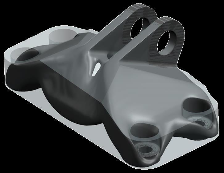
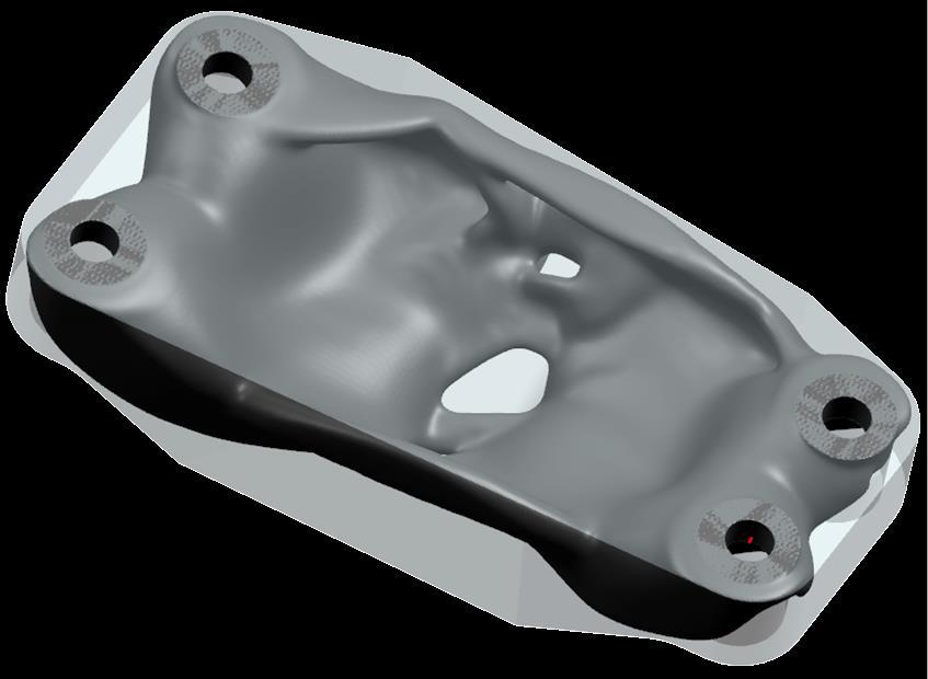
20 Geometry Results After the Optimization has completed the geometry results are displayed along with the Design Space and Optimization Features. Hiding some/all of these reveals the Optimized geometry. This is imported as a Facetted model. To do further modeling this needs to be converted to a Convergent model.


21 FEA Results The FEA results can be displayed with a Legend Displacement Stress Strain These are Max envelope for all the load cases.

22 Topology Optimization Results


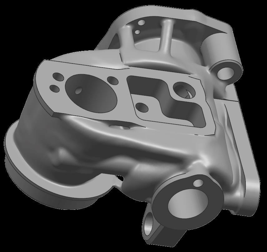

23 Courtesy of Oerlikon

24 Summary New approach to optimizing the topology within the given design space. Designer for CAD users and does not require deep CAE expertise. Focuses on the Functional Requirements of the design. Results are returned quickly. Highly smoothed Convergent model results ready for AM printing, or guidance for re-design.
25 Thank You! Realize innovation.
Convergent Modeling and Reverse Engineering
 Convergent Modeling and Reverse Engineering 25 October 2017 Realize innovation. Tod Parrella NX Design Product Management Product Engineering Solutions tod.parrella@siemens.com Realize innovation. Siemens
Types of Idealizations. Idealizations. Cylindrical Shaped Part. Cyclic Symmetry. 3D Shell Model. Axisymmetric
 Types of Idealizations Idealizations Selecting the model type 3D Solid Plane Stress Plane Strain 3D Shell Beam Cyclic Symmetry Cylindrical Shaped Part Interior Pressure Load 3D model can be used to model
MAE 323: Lab 7. Instructions. Pressure Vessel Alex Grishin MAE 323 Lab Instructions 1
 Instructions MAE 323 Lab Instructions 1 Problem Definition Determine how different element types perform for modeling a cylindrical pressure vessel over a wide range of r/t ratios, and how the hoop stress
Geometric Modeling Topics
 Geometric Modeling Topics George Allen, george.allen@siemens.com Outline General background Convergent modeling Multi-material objects Giga-face lattices Page 2 Boundary Representation (b-rep) Topology
Creo Simulate 3.0 Tutorial
 Creo Simulate 3.0 Tutorial Structure and Thermal Roger Toogood, Ph.D., P. Eng. SDC PUBLICATIONS Better Textbooks. Lower Prices. www.sdcpublications.com Powered by TCPDF (www.tcpdf.org) Visit the following
Nouveautés ANSYS pour le calcul structurel et l impression 3D. CADFEM 2017 ANSYS Additive Manufacturing
 Titelmasterformat Journée Technologique durch AddiPole Klicken bearbeiten Nouveautés ANSYS pour le calcul structurel et l impression 3D Titelmasterformat Structural design with durch ANSYS Klicken bearbeiten
Autodesk Fusion 360: Model. Overview. Modeling techniques in Fusion 360
 Overview Modeling techniques in Fusion 360 Modeling in Fusion 360 is quite a different experience from how you would model in conventional history-based CAD software. Some users have expressed that it
Introduction to Solid Modeling Parametric Modeling. Mechanical Engineering Dept.
 Introduction to Solid Modeling Parametric Modeling 1 Why draw 3D Models? 3D models are easier to interpret. Simulation under real-life conditions. Less expensive than building a physical model. 3D models
ANSYS Element. elearning. Peter Barrett October CAE Associates Inc. and ANSYS Inc. All rights reserved.
 ANSYS Element Selection elearning Peter Barrett October 2012 2012 CAE Associates Inc. and ANSYS Inc. All rights reserved. ANSYS Element Selection What is the best element type(s) for my analysis? Best
Geometric Modeling. Introduction
 Geometric Modeling Introduction Geometric modeling is as important to CAD as governing equilibrium equations to classical engineering fields as mechanics and thermal fluids. intelligent decision on the
2: Static analysis of a plate
 2: Static analysis of a plate Topics covered Project description Using SolidWorks Simulation interface Linear static analysis with solid elements Finding reaction forces Controlling discretization errors
Femap v11.2 Geometry Updates
 Femap v11.2 Geometry Updates Chip Fricke, Femap Principal Applications Engineer chip.fricke@siemens.com Femap Symposium Series 2015 June, 2015 Femap Symposium Series 2015 Femap v11.2 Geometry Creation
Femap automatic meshing simplifies virtual testing of even the toughest assignments
 Femap automatic meshing simplifies virtual testing of even the toughest assignments fact sheet Siemens PLM Software www.siemens.com/plm/femap Summary Femap version 10 software is the latest release of
Reverse Engineering Convert STL mesh data to a Solid Edge part model and speed up Product Development.
 Reverse Engineering Convert STL mesh data to a Solid Edge part model and speed up Product Development. Realize innovation. Reverse Engineering Why Reverse Engineering? Convert an existing physical part
Education Curriculum Surface Design Specialist
 Education Curriculum Surface Design Specialist Invest your time in imagining next generation designs. Here s what we will teach you to give shape to your imagination. CATIA Surface Design Specialist CATIA
SDC. Engineering Analysis with COSMOSWorks. Paul M. Kurowski Ph.D., P.Eng. SolidWorks 2003 / COSMOSWorks 2003
 Engineering Analysis with COSMOSWorks SolidWorks 2003 / COSMOSWorks 2003 Paul M. Kurowski Ph.D., P.Eng. SDC PUBLICATIONS Design Generator, Inc. Schroff Development Corporation www.schroff.com www.schroff-europe.com
pre- & post-processing f o r p o w e r t r a i n
 pre- & post-processing f o r p o w e r t r a i n www.beta-cae.com With its complete solutions for meshing, assembly, contacts definition and boundary conditions setup, ANSA becomes the most efficient and
Topology and Shape optimization within the ANSA-TOSCA Environment
 Topology and Shape optimization within the ANSA-TOSCA Environment Introduction Nowadays, manufacturers need to design and produce, reliable but still light weighting and elegant components, at minimum
Constructing treatment features
 Constructing treatment features Publication Number spse01530 Constructing treatment features Publication Number spse01530 Proprietary and restricted rights notice This software and related documentation
3D PRINTING AND CONVERGENT MODELING IN NX Patrick Barrett
 3D PRINTING AND CONVERGENT MODELING IN NX 11.0.1 Patrick Barrett www.appliedcax.com Patrick Barrett Who Am I Started using UG in 1996 Started Sherpa Design in 2001 Designed many things for many different
solidthinking Design Release Notes
 solidthinking Design 2017.2 Release Notes The solidthinking Design package includes Inspire and Evolve 2017.2. Inspire is available on Windows, while Evolve is available on Windows and Mac. solidthinking
Introduction to ANSYS DesignModeler
 Lecture 5 Modeling 14. 5 Release Introduction to ANSYS DesignModeler 2012 ANSYS, Inc. November 20, 2012 1 Release 14.5 Preprocessing Workflow Geometry Creation OR Geometry Import Geometry Operations Meshing
Modeling Bolted Connections. Marilyn Tomlin CAE COE / Siemens Corporation
 Modeling Bolted Connections Marilyn Tomlin CAE COE / Siemens Corporation Overview Bolted Connection Engineering Judgment Modeling Options Summary Typical Bolted Connection Gasket Bolt Nut Washer Technology
Exercise Guide. Published: August MecSoft Corpotation
 VisualCAD Exercise Guide Published: August 2018 MecSoft Corpotation Copyright 1998-2018 VisualCAD 2018 Exercise Guide by Mecsoft Corporation User Notes: Contents 2 Table of Contents About this Guide 4
Solid Modeling: Part 1
 Solid Modeling: Part 1 Basics of Revolving, Extruding, and Boolean Operations Revolving Exercise: Stepped Shaft Start AutoCAD and use the solid.dwt template file to create a new drawing. Create the top
SimLab 14.2 Release Notes
 SimLab 14.2 Release Notes Highlights SimLab 14.2 comes with various changes that improve performance and graphics rendering. In addition to java scripting, python scripting is introduced. The enhancements,
Metal 3D Printing. - Design for Metal 3D Printing - 10th October 2018
 Metal 3D Printing - Design for Metal 3D Printing - 10th October 2018 Agenda 1. Short Introduction Materialise 2. Design for Manufacturing / M3DP 3. General Design Process 4. Topology Optimization 5. Example
Nerf Blaster Redesign
 Nerf Blaster Redesign ME4041 Computer Graphics and CAD April 0, 010 Submitted By: Michael Schulman Greg Mann Table of Contents Introduction. Objectives Modeling. 4 External Components 4 Internal Components.
2-D Meshing. Some rules of thumb when meshing:
 VI 2-D Meshing This chapter includes material from the book Practical Finite Element Analysis. It also has been reviewed and has additional material added by Matthias Goelke. Once geometry cleanup is completed
CATIA V5 Parametric Surface Modeling
 CATIA V5 Parametric Surface Modeling Version 5 Release 16 A- 1 Toolbars in A B A. Wireframe: Create 3D curves / lines/ points/ plane B. Surfaces: Create surfaces C. Operations: Join surfaces, Split & Trim
SolidWorks 2014 Part II - Advanced Techniques
 SolidWorks 2014 Part II - Advanced Techniques Parts, Surfaces, Sheet Metal, SimulationXpress, Top-Down Assemblies, Core and Cavity Molds Paul Tran CSWE, CSWI SDC PUBLICATIONS Better Textbooks. Lower Prices.
NX Advanced 5-Axis Machining
 Siemens PLM Software NX Advanced 5-Axis Machining Benefits Automated hole making capability speeds common processes Boundary-based cutting provides flexibility to cut on minimal geometry Solids-based cutting
midas NFX An insight into midas NFX
 midas NFX An insight into midas NFX Total Analysis Solutions for Multi-disciplinary Optimum Design Part 1. Work environment Multi-disciplinary CAE solutions in one unique work environment 1 Part 1. Work
Technical Education Services
 Autodesk Fusion 360: Introduction to Parametric Modeling Course Length: 3 days Official Training Guide The Autodesk Fusion 360 Introduction to Parametric Modeling training course provides you with an understanding
Engineering Analysis with
 Engineering Analysis with SolidWorks Simulation 2013 Paul M. Kurowski SDC PUBLICATIONS Schroff Development Corporation Better Textbooks. Lower Prices. www.sdcpublications.com Visit the following websites
Geometry Definition in the ADINA User Interface (AUI) Daniel Jose Payen, Ph.D. March 7, 2016
 Daniel Jose Payen, Ph.D. March 7, 2016") Geometry Definition in the ADINA User Interface (AUI) Daniel Jose Payen, Ph.D. March 7, 2016 ADINA R&D, Inc., 2016 1 Topics Presented ADINA에서쓰이는 Geometry 종류 Simple (AUI) geometry ADINA-M geometry ADINA-M
Geometry Definition in the ADINA User Interface (AUI) Daniel Jose Payen, Ph.D. March 7, 2016 ADINA R&D, Inc., 2016 1 Topics Presented ADINA에서쓰이는 Geometry 종류 Simple (AUI) geometry ADINA-M geometry ADINA-M
Engineering Analysis with SolidWorks Simulation 2012
 Engineering Analysis with SolidWorks Simulation 2012 Paul M. Kurowski SDC PUBLICATIONS Schroff Development Corporation Better Textbooks. Lower Prices. www.sdcpublications.com Visit the following websites
PTC Newsletter January 14th, 2002
 PTC Email Newsletter January 14th, 2002 PTC Product Focus: Pro/MECHANICA (Structure) Tip of the Week: Creating and using Rigid Connections Upcoming Events and Training Class Schedules PTC Product Focus:
Geometric Modeling. Creating 3D solid geometry in a computer! MAE 455 Computer-Aided Design and Drafting
 Geometric Modeling Creating 3D solid geometry in a computer! Partial History of Geometric Modeling 1963 Wireframe Computer Graphics Invented (Ivan Sutherland, MIT) 2 Partial History 1964 DAC-1, General
Geometric Modeling Systems
 Geometric Modeling Systems Wireframe Modeling use lines/curves and points for 2D or 3D largely replaced by surface and solid models Surface Modeling wireframe information plus surface definitions supports
CATIA Surface Design
 CATIA V5 Training Exercises CATIA Surface Design Version 5 Release 19 September 2008 EDU_CAT_EN_GS1_FX_V5R19 Table of Contents (1/2) Creating Wireframe Geometry: Recap Exercises 4 Creating Wireframe Geometry:
3D Finite Element Software for Cracks. Version 3.2. Benchmarks and Validation
 3D Finite Element Software for Cracks Version 3.2 Benchmarks and Validation October 217 1965 57 th Court North, Suite 1 Boulder, CO 831 Main: (33) 415-1475 www.questintegrity.com http://www.questintegrity.com/software-products/feacrack
Autodesk Fusion 360 Training: The Future of Making Things Attendee Guide
 Autodesk Fusion 360 Training: The Future of Making Things Attendee Guide Abstract After completing this workshop, you will have a basic understanding of editing 3D models using Autodesk Fusion 360 TM to
Autodesk Inventor 2019 and Engineering Graphics
 Autodesk Inventor 2019 and Engineering Graphics An Integrated Approach Randy H. Shih SDC PUBLICATIONS Better Textbooks. Lower Prices. www.sdcpublications.com Powered by TCPDF (www.tcpdf.org) Visit the
Revised Sheet Metal Simulation, J.E. Akin, Rice University
 Revised Sheet Metal Simulation, J.E. Akin, Rice University A SolidWorks simulation tutorial is just intended to illustrate where to find various icons that you would need in a real engineering analysis.
SOLIDWORKS 2016 and Engineering Graphics
 SOLIDWORKS 2016 and Engineering Graphics An Integrated Approach Randy H. Shih SDC PUBLICATIONS Better Textbooks. Lower Prices. www.sdcpublications.com Powered by TCPDF (www.tcpdf.org) Visit the following
L1 - Introduction. Contents. Introduction of CAD/CAM system Components of CAD/CAM systems Basic concepts of graphics programming
 L1 - Introduction Contents Introduction of CAD/CAM system Components of CAD/CAM systems Basic concepts of graphics programming 1 Definitions Computer-Aided Design (CAD) The technology concerned with the
Lesson 6: Assembly Structural Analysis
 Lesson 6: Assembly Structural Analysis In this lesson you will learn different approaches to analyze the assembly using assembly analysis connection properties between assembly components. In addition
Lesson 4: Surface Re-limitation and Connection
 Lesson 4: Surface Re-limitation and Connection In this lesson you will learn how to limit the surfaces and form connection between the surfaces. Lesson contents: Case Study: Surface Re-limitation and Connection
What s new in Femap 9.3
 What s new in Femap 9.3 fact sheet www.ugs.com/femap Summary Femap version 9.3 is the latest release of UGS robust pre and post processor for engineering finite element analysis (FEA). Femap software is
Simulation of Automotive Fuel Tank Sloshing using Radioss
 Simulation of Automotive Fuel Tank Sloshing using Radioss Prashant V. Kulkarni CAE Analyst Tata Motors. Pimpri, Pune - 411018, India Sanjay S. Patil Senior Manager Tata Motors. Pimpri, Pune - 411018, India
Course in. FEM ANSYS Classic
 Course in Geometric modeling Modeling Programme for Lesson: Modeling considerations Element Type Real Constants Material Properties Sections Geometry/Modeling WorkPlane & Coordinate systems Keypoints Lines
Complex Shapes Creation with Hybrid Modelling
 Complex Shapes Creation with Hybrid Modelling Peter De Strijker Technical Sales Executive MFG - Benelux Our Customer s Industries Discrete product manufacture Agenda Quality Analyses of sketches and surfaces
SOLIDWORKS Simulation
 SOLIDWORKS Simulation Length: 3 days Prerequisite: SOLIDWORKS Essentials Description: SOLIDWORKS Simulation is designed to make SOLIDWORKS users more productive with the SOLIDWORKS Simulation Bundle. This
Advanced Webinar. Date: December 8, 2011 Topic: General Use of midas GTS (Part I) Presenter: Abid Ali, Geotechnical Engineer
 Presenter: Abid Ali, Geotechnical Engineer") midas GTS Advanced Webinar Date: December 8, 2011 Topic: General Use of midas GTS (Part I) Presenter: Abid Ali, Geotechnical Engineer Bridging Your Innovations to Realities Contents: 1. Introduction 2.
midas GTS Advanced Webinar Date: December 8, 2011 Topic: General Use of midas GTS (Part I) Presenter: Abid Ali, Geotechnical Engineer Bridging Your Innovations to Realities Contents: 1. Introduction 2.
PARAMETRIC MODELING FOR MECHANICAL COMPONENTS 1
 PARAMETRIC MODELING FOR MECHANICAL COMPONENTS 1 Wawre S.S. Abstract: parametric modeling is a technique to generalize specific solid model. This generalization of the solid model is used to automate modeling
CREO ENGINEER PACKAGES. 3D CAD solutions optimized for your product development tasks
 CREO ENGINEER PACKAGES 3D CAD solutions optimized for your product development tasks From the smallest product design firm to the largest, manufacturing organizations are under constant pressure to develop
Lesson: Lightweighting of Robot Gripper Arm
 Lesson: Lightweighting of Robot Gripper Arm This functionality is only available in Fusion 360 Ultimate. In this exercise we'll perform a Shape Optimization study to reduce the weight of a robot gripper
New Frontiers in CAE Interoperability. Andy Chinn ITI TranscenData
 New Frontiers in CAE Interoperability Andy Chinn ITI TranscenData arc@transcendata.com Introduction Data Exchange Integrity Issue of Meshability Geometry Reasoning Geometry Reasoning Applications Conclusions
4) Finish the spline here. To complete the spline, double click the last point or select the spline tool again.
 Finish the spline here. To complete the spline, double click the last point or select the spline tool again.") 1) Select the line tool 3) Move the cursor along the X direction (be careful to stay on the X axis alignment so that the line is perpendicular) and click for the second point of the line. Type 0.5 for
1) Select the line tool 3) Move the cursor along the X direction (be careful to stay on the X axis alignment so that the line is perpendicular) and click for the second point of the line. Type 0.5 for
Introduction to Solid Modeling
 Introduction to Solid Modeling Parametric Modeling 1 Why draw 3D Models? 3D models are easier to interpret. 3D models can be used to perform engineering analysis, finite element analysis (stress, deflection,
105 - Synchronizing History
 4 th Generation VLC courtesy of Edison2 105 - Synchronizing History Matt Lombard, Solid Edge Employee #SEU13 Agenda: 105 - Synchronizing History Who is Matt Lombard? Why you should mix methods (Synchronous
World-class finite element analysis (FEA) solution for the Windows desktop
 solution for the Windows desktop") World-class finite element analysis (FEA) solution for the Windows desktop Benefits Significantly speed up the design process by bringing simulation closer to design and reducing time-to-market Reduce
World-class finite element analysis (FEA) solution for the Windows desktop Benefits Significantly speed up the design process by bringing simulation closer to design and reducing time-to-market Reduce
PTC Creo Simulate. Features and Specifications. Data Sheet
 PTC Creo Simulate PTC Creo Simulate gives designers and engineers the power to evaluate structural and thermal product performance on your digital model before resorting to costly, time-consuming physical
TOPOLOGICAL OPTIMIZATION OF STEERING KNUCKLE BY USING ADDITIVE MANUFACTURING PROCESS
 TOPOLOGICAL OPTIMIZATION OF STEERING KNUCKLE BY USING ADDITIVE MANUFACTURING PROCESS Prof.P.S.Gorane 1,Mr. Piyush Jain 2 Mechanical engineering, G. S.Mozecollege of engineering, Savitri Bai Phule Pune
SimLab Release Notes. 1 A l t a i r E n g i n e e r i n g
 SimLab 11.0 Release Notes 1 A l t a i r E n g i n e e r i n g System Support extended to load and save GDA/SLB files of size greater than 4GB. Memory allocation is enhanced to support large models. Kubrix
#SEU Welcome! Solid Edge University 2016
 #SEU 2016 Welcome! Solid Edge University 2016 Realize innovation. Reverse Engineering Convert STL mesh data to a Solid Edge part model and speed up Product Development. Realize innovation. About me Sandeep
Step 1: Open the CAD model
 In this exercise you will learn how to: Ground a part Create rigid groups Add joints and an angle motor Add joints and an angle motor Run both transient and statics motion analyses Apply shape controls
Version 4.1 Demo. RecurDynTM 2002 RecurDyn User Conference
 Version 4.1 Demo RecurDynTM 2002 RecurDyn User Conference What s New? Using Parasolid Kernel Solid Modeler Other Program Interfaces New Data Structure New & Improved Features What s New? Using Parasolid
Topology Optimization of an Engine Bracket Under Harmonic Loads
 Topology Optimization of an Engine Bracket Under Harmonic Loads R. Helfrich 1, A. Schünemann 1 1: INTES GmbH, Schulze-Delitzsch-Str. 16, 70565 Stuttgart, Germany, www.intes.de, info@intes.de Abstract:
3D Modeling and Design Glossary - Beginner
 3D Modeling and Design Glossary - Beginner Align: to place or arrange (things) in a straight line. To use the Align tool, select at least two objects by Shift left-clicking on them or by dragging a box
SolidWorks. An Overview of SolidWorks and Its Associated Analysis Programs
 An Overview of SolidWorks and Its Associated Analysis Programs prepared by Prof. D. Xue University of Calgary SolidWorks - a solid modeling CAD tool. COSMOSWorks - a design analysis system fully integrated
World-class finite element analysis (FEA) solution for the Windows desktop
 solution for the Windows desktop") World-class finite element analysis (FEA) solution for the Windows desktop fact sheet Siemens PLM Software www.siemens.com/plm/femap Summary Femap software is an advanced engineering analysis environment
World-class finite element analysis (FEA) solution for the Windows desktop fact sheet Siemens PLM Software www.siemens.com/plm/femap Summary Femap software is an advanced engineering analysis environment
The basics of NX CAD
 The basics of NX CAD 1) Creation of a new file: Go to File/New/Model and create a model part named Cantilever. Create a folder for your project and save every file on it. 2) Start a new Sketch and draw
Customized Pre/post-processor for DIANA. FX for DIANA
 Customized Pre/post-processor for DIANA FX for DIANA About FX4D for DIANA FX4D is a general purpose pre/post-processor for CAE simulation. FX4D has been specialized for civil/architectural applications.
Materialise Magics 23. What s new
 Materialise Magics 23 What s new Index UX/UI Improvements View cube and general toolbar Settings Performance improvements Magics RP Fillet Cut or punch: lap joint cut Boolean Honeycomb structures Tools
Introduction to FEM Modeling
 Total Analysis Solution for Multi-disciplinary Optimum Design Apoorv Sharma midas NFX CAE Consultant 1 1. Introduction 2. Element Types 3. Sample Exercise: 1D Modeling 4. Meshing Tools 5. Loads and Boundary
Parametric Piping Models. Naveed Anwar July 2003
 Parametric Piping Models Naveed Anwar July 2003 The Idea Basic idea is to assign parametric objects to basic line or area objects in the SAP2000 model and then generate detailed mesh for each object, on-demand
Character Modeling COPYRIGHTED MATERIAL
 38 Character Modeling p a r t _ 1 COPYRIGHTED MATERIAL 39 Character Modeling Character Modeling 40 1Subdivision & Polygon Modeling Many of Maya's features have seen great improvements in recent updates
Finite Element Analysis Using Creo Simulate 4.0
 Introduction to Finite Element Analysis Using Creo Simulate 4.0 Randy H. Shih SDC PUBLICATIONS Better Textbooks. Lower Prices. www.sdcpublications.com Powered by TCPDF (www.tcpdf.org) Visit the following
Quick Surface Reconstruction
 CATIA V5 Training Exercises Quick Surface Reconstruction Version 5 Release 19 August 2008 EDU_CAT_EN_QSR_FX_V5R19 1 Table of Contents Master Exercise Presentation:Plastic Bottle 3 Design Intent - Plastic
Geometric Modeling. Creating 3D solid geometry in a computer! Partial History of Geometric Modeling
 Geometric Modeling Creating 3D solid geometry in a computer! Partial History of Geometric Modeling 1963 Wireframe Computer Graphics Invented (Ivan Sutherland, MIT) 2 1 Partial History 1964 DAC-1, General
Wayne Mahan, GTAC. Converting a Solid Body to Sheet Metal
 Wayne Mahan, GTAC Converting a Solid Body to Sheet Metal Realize innovation. About Myself Page 2 Wayne Mahan Application Engineer, GTAC Solid Edge wayne.mahan@siemens.com I am a GTAC Application Engineer
SimLab 14.1 Release Notes
 SimLab 14.1 Release Notes Highlights SimLab 14.0 introduced the new user interface. SimLab 14.1 enhances the user interface using feedback from customers. In addition many new core features have been added.
Example Plate with a hole
 Course in ANSYS Example Plate with a hole A Objective: Determine the maximum stress in the x-direction for point A and display the deformation figure Tasks: Create a submodel to increase the accuracy of
CAD/CAM COURSE TOPIC OF DISCUSSION GEOMETRIC MODELING DAWOOD COLLEGE OF ENGINEERING & TECHNOLOGY- KARACHI- ENGR. ASSAD ANIS 4/16/2011 1
 CAD/CAM COURSE TOPIC OF DISCUSSION GEOMETRIC MODELING 1 CAD attempts to eliminate the need of developing a prototype for testing and optimizing the design CAD evaluates a design using a model with geometric
Introduction to ANSYS DesignModeler
 Lecture 9 Beams and Shells 14. 5 Release Introduction to ANSYS DesignModeler 2012 ANSYS, Inc. November 20, 2012 1 Release 14.5 Beams & Shells The features in the Concept menu are used to create and modify
First Order Analysis for Automotive Body Structure Design Using Excel
 Special Issue First Order Analysis 1 Research Report First Order Analysis for Automotive Body Structure Design Using Excel Hidekazu Nishigaki CAE numerically estimates the performance of automobiles and
Engineering designs today are frequently
 Basic CAD Engineering designs today are frequently constructed as mathematical solid models instead of solely as 2D drawings. A solid model is one that represents a shape as a 3D object having mass properties.
BobCAD CAM V25 4 Axis Standard Posted by Al /09/20 22:03
 BobCAD CAM V25 4 Axis Standard Posted by Al - 2012/09/20 22:03 Many BobCAD CAM clients that run a 4 axis have requested to work directly with Solids or STL files. In the past we only offered 4 axis indexing
Computer Aided Engineering Applications
 Computer Aided Engineering Applications 1A.Geometric Modeling 1.1 Geometric modelling methods 1.2 Data representation 1.3 Modeling functions 1.4 Structure of a CAD system Engi 6928 - Fall 2014 1.Geometric
ANSYS AIM Tutorial Structural Analysis of a Plate with Hole
 ANSYS AIM Tutorial Structural Analysis of a Plate with Hole Author(s): Sebastian Vecchi, ANSYS Created using ANSYS AIM 18.1 Problem Specification Pre-Analysis & Start Up Analytical vs. Numerical Approaches
3D Modeling: Solid Models
 CS 430/536 Computer Graphics I 3D Modeling: Solid Models Week 9, Lecture 18 David Breen, William Regli and Maxim Peysakhov Geometric and Intelligent Computing Laboratory Department of Computer Science
Engineering Analysis
 Engineering Analysis with SOLIDWORKS Simulation 2018 Paul M. Kurowski SDC PUBLICATIONS Better Textbooks. Lower Prices. www.sdcpublications.com Powered by TCPDF (www.tcpdf.org) Visit the following websites
(Based on a paper presented at the 8th International Modal Analysis Conference, Kissimmee, EL 1990.)
") Design Optimization of a Vibration Exciter Head Expander Robert S. Ballinger, Anatrol Corporation, Cincinnati, Ohio Edward L. Peterson, MB Dynamics, Inc., Cleveland, Ohio David L Brown, University of Cincinnati,
Design Optimization of a Vibration Exciter Head Expander Robert S. Ballinger, Anatrol Corporation, Cincinnati, Ohio Edward L. Peterson, MB Dynamics, Inc., Cleveland, Ohio David L Brown, University of Cincinnati,
ANSYS Workbench Guide
 ANSYS Workbench Guide Introduction This document serves as a step-by-step guide for conducting a Finite Element Analysis (FEA) using ANSYS Workbench. It will cover the use of the simulation package through
Introduction. File preparation
 White Paper Design and printing guidelines Introduction A print job can be created in either of the following ways: NOTE: HP SmartStream 3D Build Manager supports STL and 3MF files. By using the HP SmartStream
Introduction to Synchronous Modeling
 #SEU15 Introduction to Synchronous Modeling Craig Ruchti Global Technical Business Development Applications Engineer Realize innovation. Introduction to Synchronous Technology Agenda Introduction Synchronous
SpaceClaim Professional The Natural 3D Design System. Advanced Technology
 SpaceClaim Professional The Natural 3D Design System SpaceClaim Professional is the 3D productivity tool for engineers who contribute to the design and manufacture of mechanical products across a broad
6. CAD SOFTWARE. CAD is a really useful tool for every engineer, and especially for all the designers.
 6. CAD SOFTWARE CAD is a really useful tool for every engineer, and especially for all the designers. Not only because it makes drawing easier, but because it presents the advantage that if any detail