Geometry of Aerial photogrammetry. Panu Srestasathiern, PhD. Researcher Geo-Informatics and Space Technology Development Agency (Public Organization)
|
|
|
- Dominick Pope
- 6 years ago
- Views:
Transcription


1 Geometry of Aerial photogrammetry Panu Srestasathiern, PhD. Researcher Geo-Informatics and Space Technology Development Agency (Public Organization)
2 Image formation - Recap The geometry of imaging system pixel coordinate system x 1 image coordinate system camera coordinate system (R,T) world coordinate system
3 Types of aerial photograph Vertical Low oblique High oblique Camera film plane Vertical Aerial Photograph Over Level Terrain Altitude above-groundlevel (AGL) field of view Optical axis Principal point (PP) 90
4 Vertical Types of aerial photograph Low oblique (no horizon) High oblique


5 Types of aerial photograph Vertical Low oblique High oblique High-Oblique Aerial Photograph Over Flat Terrain field of view Optical axis Horizon is shown in the photograph 90

6 Types of aerial photograph In mapping application, vertical photograph is preferred. In some applications, particularly, close range photogrammetry or 3D modeling, oblique photographs are useful.

7 Scale = f /H = d/d Image scale (vertical image) Representative fraction (e.g., 1:50,000) = 1/(H /f) where f = focal length d = image distance D = ground distance h = terrain elevation H = flying height (h + H ) H = height above terrain = H - h
8 Image scale (vertical image) Datum Scale = All the points of photograph are assumed to be projected on M.S.L. Datum scale = f/h Average Scale = All the points of photograph are asumed to be having average elevation above m.s.l. Average scale = f/(h ave -h)
9 Other methods of finding scale of vertical photograph By measuring Ground distance By determining the distance from existing map
10 Example: Image Scale vs. flying height example If I want a ground coverage of 5km, what flying height should I use? Scale = f /H = d/d where f = 150 mm D = 5000m d = 250mm H =?
11 Example: Image Scale vs. flying height example If I want a scale of 1/50,000, what flying height should I use? Scale = 1/50,000 = f /H where f = 152 mm H =?
12 Effect of flying height on ground coverage
13 Effect of focal length on ground coverage
14 Ground Coverage Ground coverage, D, of photo frame varies with f and H as f decreases, ground coverage increases e.g. f 1 = 1/2 f 2 D 1 = 2D 2 A 1 = 4A 2 as H increases, ground coverage increases e.g. H 2 = 2H 1 D 2 = 2D 1 A 2 = 4A 1
15 Ground Sampling Distance The Ground Sampling Distance (GSD) is the distance between two consecutive pixel centers measured on the ground. The higher the altitude of the flight, the bigger the GSD value. The bigger the value of the image GSD, the lower the spatial resolution of the image and the less visible details.
16 Exercise What Flying Height (m) needed to resolve individual of 15 cm wide x 50 cm long using Sony Alpha NEX-5T at max resolution and 50mm lens? (General Rule of Thumb: GSD at a minimum of ½ the size of smallest feature.)


17 Relief displacement Relief Displacement exists because photos are a perspective projection.
18 Relief displacement The scale of an aerial photograph is partly a function of flying height. Thus, variations in elevation cause variations in scale on aerial photographs. Specifically, the higher the elevation of an object, the farther the object will be displaced from its actual position away from the principal point of the photograph (the point on the ground surface that is directly below the camera lens).

19
20 Relief displacement

21 Aerial triangulation Aerial triangulation is the term applied to the process of determining x,y and z Ground coordinate of individual points on measurements from the photograph. The bundle adjustment is performed to solve aerial triangulation problem.
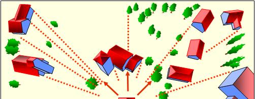
22 What is Bundle Adjustment? Refines a visual reconstruction to produce jointly optimal 3D structure (x,y and z Ground coordinate of individual points ) and viewing parameters (exterior orientation of camera) bundle refers to the bundle of light rays leaving each 3D feature and converging on each camera center.

23 What is Bundle Adjustment?
24 What is Bundle Adjustment? Ground Control Points (GCPs) are used to control the result from bundle adjustment to be in the reference coordinate system.
25 Bundle adjustment without GCP Without GCP, bundle adjustment can be performed; but the recovered 3D structure and camera orientations are in independent coordinate system. The camera orientation estimated without GCP is called relative orientation. Bundle adjustment with GCP is then called absolute orientation. In other words, relative orientation is the process of orienting images relative to one another. Without GCP, the scale of 3D object is incorrect.
26 Airborne GPS support Aerial triangulation Airborne GPS support Aerial triangulation is performed in order to get equal precision as usual by less number of ground controls. Airborne GPS is used to locate the exposure positions of camera.
27 Airborne GPS support Aerial triangulation Airborne GPS support Aerial triangulation is also called Direct geo-referencing. Aerial triangulation using GCP only is also called In-direct geo-referencing.


28 Making map with UAV Motivation: direct georeferencing!!!!!!
29 Direct georeferencing: pros Integrated georeferencing is optimal (provides exterior orientation with best accuracy and reliability). Bundling sensor and direct georeferencing on one platform can increase efficiency (ease of deployment, speed of delivery, ) Indirect georeferencing is not always possible or feasible too low redundancy (no control points ) Singularity in system of observation equations (image taken over flat scene) when performing non-linear optimization.
30 Direct georeferencing: cons Direct georeferencing method needs to be adapted to environment (indoor positioning, etc.) Additional costs and complexity because of additional sensors. Mounting and possibly other as additional unknowns (constant?)
31 Where is the exterior orientation stored? To perform direct geo-referencing, the GPS/INS information (exterior orientation parameters) must be imported to processing software. There are two ways to store exterior orientation parameters: EXIF data Image geolocation file e.g., CSV text file

32 Sensors EXIF Data The purpose of a camera is to take a picture, and EXIF data tells a story about the camera and where it was taking pictures.
33 Image geolocation file If the image EXIF data contains the image position, then the geolocation file is not needed as processing software automatically reads the geolocation from the EXIF data. If the EXIF data does not contain the image GPS position, then a geolocation file is needed. The files that can be imported in are: Latitude, Longitude, Altitude (Geo-graphic coordinate system) X, Y, Z (Projected coordinate system).
34 Image geolocation file Example: WGS84 geographic coordinates imagename,latitude [decimal degrees],longitude [decimal degrees],altitude [meter] IMG_3165.JPG, , , IMG_3166.JPG, , , The latitude value is between -90 and 90. The longitude value is between -180 and 180 Example: WGS84 geographic coordinates including orientation imagename,latitude[decimal degrees],longitude [decimal degrees],altitude [meter],omega [degrees], phi [degrees], kappa [degrees] IMG_3165.JPG, , , ,1.698,4.392, IMG_3166.JPG, , , ,4.571,2.977,94.714
35 Photo overlap Endlap Endlap, also known as forward overlap, is the common image area on consecutive photographs along a flight strip. This overlapping portion of two successive aerial photos, which creates the three-dimensional effect necessary for mapping, is known as a stereomodel or more commonly as a model.
36 Photo overlap Endlap D = Sensor size H = Flying height f = Focal length L = Percent overlap E = distance between exposure stations
37 Photo overlap Sidelap Sidelap, sometimes called side overlap, encompasses the overlapping areas of photographs between adjacent flight lines. It is designed so that there are no gaps in the threedimensional coverage of a multiline project
38 Photo overlap Sidelap D = Sensor size H = Flying height f = Focal length L = Percent overlap C = distance between flight line center
39 Number of flight lines Where NL = number of flight line W = width of study area C = Distance between flight line 2 = extra flight lines (1 per side)
40 Number of photos per flight line Where NP = number of photos per flight line FL = Length of flight line E = Distance between exposure station 4 = extra photos (2 per end of flight line)
Chapters 1 9: Overview
 Chapters 1 9: Overview Chapter 1: Introduction Chapters 2 4: Data acquisition Chapters 5 9: Data manipulation Chapter 5: Vertical imagery Chapter 6: Image coordinate measurements and refinements Chapters
TRAINING MATERIAL HOW TO OPTIMIZE ACCURACY WITH CORRELATOR3D
 TRAINING MATERIAL WITH CORRELATOR3D Page2 Contents 1. UNDERSTANDING INPUT DATA REQUIREMENTS... 4 1.1 What is Aerial Triangulation?... 4 1.2 Recommended Flight Configuration... 4 1.3 Data Requirements for
Photogrammetry: DTM Extraction & Editing
 Photogrammetry: DTM Extraction & Editing Review of terms Vertical aerial photograph Perspective center Exposure station Fiducial marks Principle point Air base (Exposure Station) Digital Photogrammetry:
Chapters 1 7: Overview
 Chapters 1 7: Overview Chapter 1: Introduction Chapters 2 4: Data acquisition Chapters 5 7: Data manipulation Chapter 5: Vertical imagery Chapter 6: Image coordinate measurements and refinements Chapter
Reality Modeling Drone Capture Guide
 Reality Modeling Drone Capture Guide Discover the best practices for photo acquisition-leveraging drones to create 3D reality models with ContextCapture, Bentley s reality modeling software. Learn the
Exterior Orientation Parameters
 Exterior Orientation Parameters PERS 12/2001 pp 1321-1332 Karsten Jacobsen, Institute for Photogrammetry and GeoInformation, University of Hannover, Germany The georeference of any photogrammetric product
Chapters 1-4: Summary
 Chapters 1-4: Summary So far, we have been investigating the image acquisition process. Chapter 1: General introduction Chapter 2: Radiation source and properties Chapter 3: Radiation interaction with
ifp Universität Stuttgart Performance of IGI AEROcontrol-IId GPS/Inertial System Final Report
 Universität Stuttgart Performance of IGI AEROcontrol-IId GPS/Inertial System Final Report Institute for Photogrammetry (ifp) University of Stuttgart ifp Geschwister-Scholl-Str. 24 D M. Cramer: Final report
Lecture 5. Relief displacement. Parallax. Monoscopic and stereoscopic height measurement. Photo Project. Soft-copy Photogrammetry.
 NRMT 2270, Photogrammetry/Remote Sensing Lecture 5 Relief displacement. Parallax. Monoscopic and stereoscopic height measurement. Photo Project. Soft-copy Photogrammetry. Tomislav Sapic GIS Technologist
Introduction Photogrammetry Photos light Gramma drawing Metron measure Basic Definition The art and science of obtaining reliable measurements by mean
 Photogrammetry Review Neil King King and Associates Testing is an art Introduction Read the question Re-Read Read The question What is being asked Answer what is being asked Be in the know Exercise the
Chapter 1: Overview. Photogrammetry: Introduction & Applications Photogrammetric tools:
 Chapter 1: Overview Photogrammetry: Introduction & Applications Photogrammetric tools: Rotation matrices Photogrammetric point positioning Photogrammetric bundle adjustment This chapter will cover the
Quality Report Generated with version
 Quality Report Generated with version 1.3.54 Important: Click on the different icons for: Help to analyze the results in the Quality Report Additional information about the feature Click here for additional
Drone2Map: an Introduction. October 2017
 Drone2Map: an Introduction October 2017 Drone2Map: An Introduction Topics: - Introduction to Drone Mapping - Coordinate Systems - Overview of Drone2Map - Basic Drone2Map Workflow - 2D Data Processing -
REMOTE SENSING LiDAR & PHOTOGRAMMETRY 19 May 2017
 REMOTE SENSING LiDAR & PHOTOGRAMMETRY 19 May 2017 SERVICES Visual Inspections Digital Terrain Models Aerial Imagery Volume Computations Thermal Inspections Photo maps Aerial Video Training & Consultancy
Low-Cost Orthophoto Production Using OrthoMapper Software
 Low-Cost Orthophoto Production Using OrthoMapper Software Rick Day Penn State Cooperative Extension, Geospatial Technology Program, RGIS-Chesapeake Air Photos Historical air photos are available from a
Quality Report Generated with version
 Quality Report Generated with version 3.3.67 Important: Click on the different icons for: Help to analyze the results in the Quality Report Additional information about the feature Click here for additional
Quality Report Generated with Postflight Terra 3D version
 Quality Report Generated with Postflight Terra 3D version 4.0.89 Important: Click on the different icons for: Help to analyze the results in the Quality Report Additional information about the sections
Photogrammetry: DTM Extraction & Editing
 Photogrammetry: DTM Extraction & Editing How can one determine the x, y, and z of a location? Approaches to DTM Extraction Ground surveying Digitized topographic maps Traditional photogrammetry Hardcopy
Digital Photogrammetric System. Version 5.3 USER GUIDE. Processing of UAV data
 Digital Photogrammetric System Version 5.3 USER GUIDE Table of Contents 1. Workflow of UAV data processing in the system... 3 2. Create project... 3 3. Block forming... 5 4. Interior orientation... 6 5.
Tutorial (Beginner level): Orthomosaic and DEM Generation with Agisoft PhotoScan Pro 1.3 (with Ground Control Points)
: Orthomosaic and DEM Generation with Agisoft PhotoScan Pro 1.3 (with Ground Control Points)") Tutorial (Beginner level): Orthomosaic and DEM Generation with Agisoft PhotoScan Pro 1.3 (with Ground Control Points) Overview Agisoft PhotoScan Professional allows to generate georeferenced dense point
Tutorial (Beginner level): Orthomosaic and DEM Generation with Agisoft PhotoScan Pro 1.3 (with Ground Control Points) Overview Agisoft PhotoScan Professional allows to generate georeferenced dense point
Quality Report Generated with Pix4Ddiscovery version
 Quality Report Generated with Pix4Ddiscovery version 3.1.22 Important: Click on the different icons for: Help to analyze the results in the Quality Report Additional information about the sections Click
CHAPTER 10. Digital Mapping and Earthwork
 CHAPTER 10 Digital Mapping and Earthwork www.terrainmap.com/rm22.html CE 316 March 2012 348 10.1 Introduction 349 10.2 Single Images 10.2.1 Rectified Photograph With a single photograph, X,Y data can be
Processed :36:54 Average Ground Sampling Distance (GSD) Time for Initial Processing (without report)
 Time for Initial Processing (without report)") Important: Click on the different icons for: Dronedata Back Office Server Generated Quality Report Phase 1 Time 07h:33m:02s Phase 2 Time 02h:58m:08s Phase 3 Time Not Applicable Total Time All Phases 10h:31m:08s
Important: Click on the different icons for: Dronedata Back Office Server Generated Quality Report Phase 1 Time 07h:33m:02s Phase 2 Time 02h:58m:08s Phase 3 Time Not Applicable Total Time All Phases 10h:31m:08s
Tutorial (Beginner level): Orthomosaic and DEM Generation with Agisoft PhotoScan Pro 1.3 (without Ground Control Points)
: Orthomosaic and DEM Generation with Agisoft PhotoScan Pro 1.3 (without Ground Control Points)") Tutorial (Beginner level): Orthomosaic and DEM Generation with Agisoft PhotoScan Pro 1.3 (without Ground Control Points) Overview Agisoft PhotoScan Professional allows to generate georeferenced dense point
Tutorial (Beginner level): Orthomosaic and DEM Generation with Agisoft PhotoScan Pro 1.3 (without Ground Control Points) Overview Agisoft PhotoScan Professional allows to generate georeferenced dense point
Accuracy Assessment of POS AVX 210 integrated with the Phase One ixu150
 White Paper 3/17/2016 Accuracy Assessment of POS AVX 210 integrated with the Phase One ixu150 Omer Mian, Joe Hutton, Greg Lipa, James Lutes, Damir Gumerov, Srdjan Sobol Applanix, William Chan - GeoPixel
2. POINT CLOUD DATA PROCESSING
 Point Cloud Generation from suas-mounted iphone Imagery: Performance Analysis A. D. Ladai, J. Miller Towill, Inc., 2300 Clayton Road, Suite 1200, Concord, CA 94520-2176, USA - (andras.ladai, jeffrey.miller)@towill.com
POSITIONING A PIXEL IN A COORDINATE SYSTEM
 GEOREFERENCING AND GEOCODING EARTH OBSERVATION IMAGES GABRIEL PARODI STUDY MATERIAL: PRINCIPLES OF REMOTE SENSING AN INTRODUCTORY TEXTBOOK CHAPTER 6 POSITIONING A PIXEL IN A COORDINATE SYSTEM The essential
ADS40 Calibration & Verification Process. Udo Tempelmann*, Ludger Hinsken**, Utz Recke*
 ADS40 Calibration & Verification Process Udo Tempelmann*, Ludger Hinsken**, Utz Recke* *Leica Geosystems GIS & Mapping GmbH, Switzerland **Ludger Hinsken, Author of ORIMA, Konstanz, Germany Keywords: ADS40,
Quality Report Generated with Pro version
 Quality Report Generated with Pro version 2.2.22 Important: Click on the different icons for: Help to analyze the results in the Quality Report Additional information about the sections Click here for
SimActive and PhaseOne Workflow case study. By François Riendeau and Dr. Yuri Raizman Revision 1.0
 SimActive and PhaseOne Workflow case study By François Riendeau and Dr. Yuri Raizman Revision 1.0 Contents 1. Introduction... 2 1.1. Simactive... 2 1.2. PhaseOne Industrial... 2 2. Testing Procedure...
Near-Infrared Dataset. 101 out of 101 images calibrated (100%), all images enabled
, all images enabled") Dronedata Back Office Server Generated Quality Report Phase 1 Time 01h:22m:16s Phase 2 Time 00h:11m:39s Phase 3 Time 00h:01m:40s Total Time All Phases 01:35m:35s Generated with Pix4Dmapper Pro - TRIAL
Dronedata Back Office Server Generated Quality Report Phase 1 Time 01h:22m:16s Phase 2 Time 00h:11m:39s Phase 3 Time 00h:01m:40s Total Time All Phases 01:35m:35s Generated with Pix4Dmapper Pro - TRIAL
Phototriangulation Introduction
 Introduction Photogrammetry aims to the reconstruction of the 3D object-space from the 2D image-space, thus leading to the computation of reliable, indirect measurements of 3D coordinates in the object-space
Extracting Elevation from Air Photos
 Extracting Elevation from Air Photos TUTORIAL A digital elevation model (DEM) is a digital raster surface representing the elevations of a terrain for all spatial ground positions in the image. Traditionally
EVOLUTION OF POINT CLOUD
 Figure 1: Left and right images of a stereo pair and the disparity map (right) showing the differences of each pixel in the right and left image. (source: https://stackoverflow.com/questions/17607312/difference-between-disparity-map-and-disparity-image-in-stereo-matching)
28 out of 28 images calibrated (100%), all images enabled. 0.02% relative difference between initial and optimized internal camera parameters
, all images enabled. 0.02% relative difference between initial and optimized internal camera parameters") Dronedata Render Server Generated Quality Report Phase 1 Time 00h:01m:56s Phase 2 Time 00h:04m:35s Phase 3 Time 00h:13m:45s Total Time All Phases 00h:20m:16s Generated with Pix4Dmapper Pro - TRIAL version
Dronedata Render Server Generated Quality Report Phase 1 Time 00h:01m:56s Phase 2 Time 00h:04m:35s Phase 3 Time 00h:13m:45s Total Time All Phases 00h:20m:16s Generated with Pix4Dmapper Pro - TRIAL version
ArcMap as a quality assurance tool in Photogrammetry Ron Frederiks. Abstract
 ArcMap as a quality assurance tool in Photogrammetry Ron Frederiks Abstract This paper presents the use of ArcMap, 3-D Analyst, Spatial Analyst and Ianko s ETGeoWizards to perform quality assurance of
THE INTERIOR AND EXTERIOR CALIBRATION FOR ULTRACAM D
 THE INTERIOR AND EXTERIOR CALIBRATION FOR ULTRACAM D K. S. Qtaishat, M. J. Smith, D. W. G. Park Civil and Environment Engineering Department, Mu ta, University, Mu ta, Karak, Jordan, 61710 khaldoun_q@hotamil.com
Quality Report Generated with Pix4Dmapper Pro version
 Quality Report Generated with Pix4Dmapper Pro version 3.1.23 Important: Click on the different icons for: Help to analyze the results in the Quality Report Additional information about the sections Click
Drone2Map for ArcGIS: Bring Drone Imagery into ArcGIS. Will
 Drone2Map for ArcGIS: Bring Drone Imagery into ArcGIS Will Meyers @MeyersMaps A New Window on the World Personal Mapping for Micro-Geographies Accurate High Quality Simple Low-Cost Drone2Map for ArcGIS
Creating an Event Theme from X, Y Data
 Creating an Event Theme from X, Y Data In Universal Transverse Mercator (UTM) Coordinates Eastings (measured in meters) typically have 6 digits left of the decimal. Northings (also in meters) typically
LiDAR & Orthophoto Data Report
 LiDAR & Orthophoto Data Report Tofino Flood Plain Mapping Data collected and prepared for: District of Tofino, BC 121 3 rd Street Tofino, BC V0R 2Z0 Eagle Mapping Ltd. #201 2071 Kingsway Ave Port Coquitlam,
Quality Report Generated with Pix4Dmapper Pro version
 Quality Report Generated with Pix4Dmapper Pro version 3.2.23 Important: Click on the different icons for: Help to analyze the results in the Quality Report Additional information about the sections Click
Laptop Generated Quality Report Phase 1 Time 00h:26m:45s Phase 2 Time 02h:30m:06s Phase 3 Time 01h:20m:19s Total Time All phases 04h:17m:10s
 Laptop Generated Quality Report Phase 1 Time 00h:26m:45s Phase 2 Time 02h:30m:06s Phase 3 Time 01h:20m:19s Total Time All phases 04h:17m:10s Generated with Pix4Dmapper Pro - TRIAL version 2.0.104 Important:
1. Introduction. A CASE STUDY Dense Image Matching Using Oblique Imagery Towards All-in- One Photogrammetry
 Submitted to GIM International FEATURE A CASE STUDY Dense Image Matching Using Oblique Imagery Towards All-in- One Photogrammetry Dieter Fritsch 1, Jens Kremer 2, Albrecht Grimm 2, Mathias Rothermel 1
Paris-Le Bourget Airport. 557 out of 557 images calibrated (100%), all images enabled
, all images enabled") DroneData Render Server Generated Quality Report Phase 1 Time 00h:27m:34s Phase 2 Time 01h:40m:23s Phase 3 Time 01h:41m:18s Total Time All Phases 03h:48m:59s Generated with Pix4Dmapper Pro - TRIAL version
DroneData Render Server Generated Quality Report Phase 1 Time 00h:27m:34s Phase 2 Time 01h:40m:23s Phase 3 Time 01h:41m:18s Total Time All Phases 03h:48m:59s Generated with Pix4Dmapper Pro - TRIAL version
Training i Course Remote Sensing Basic Theory & Image Processing Methods September 2011
 Training i Course Remote Sensing Basic Theory & Image Processing Methods 19 23 September 2011 Geometric Operations Michiel Damen (September 2011) damen@itc.nl ITC FACULTY OF GEO-INFORMATION SCIENCE AND
TO Ka Yi, Lizzy 6 May
 TO Ka Yi, Lizzy 6 May 2017 1 Contents Basic concepts Practical Issues Examples 2 Data Acquisition Source of Energy Data Products Interpretation & Analysis Digital Propagation through the atmosphere Data
a Geo-Odyssey of UAS LiDAR Mapping Henno Morkel UAS Segment Specialist DroneCon 17 May 2018
 a Geo-Odyssey of UAS LiDAR Mapping Henno Morkel UAS Segment Specialist DroneCon 17 May 2018 Abbreviations UAS Unmanned Aerial Systems LiDAR Light Detection and Ranging UAV Unmanned Aerial Vehicle RTK Real-time
Measurement of Direction: Bearing vs. Azimuth
 Week 5 Monday Measurement of Direction: Bearing vs. Azimuth Bearing Is an angle of 90 o or less Measured from either North or South in easterly & westerly directions. North 22 o West, South 89 o West,
Chapters 1 5. Photogrammetry: Definition, introduction, and applications. Electro-magnetic radiation Optics Film development and digital cameras
 Chapters 1 5 Chapter 1: Photogrammetry: Definition, introduction, and applications Chapters 2 4: Electro-magnetic radiation Optics Film development and digital cameras Chapter 5: Vertical imagery: Definitions,
INVESTIGATION OF 1:1,000 SCALE MAP GENERATION BY STEREO PLOTTING USING UAV IMAGES
 INVESTIGATION OF 1:1,000 SCALE MAP GENERATION BY STEREO PLOTTING USING UAV IMAGES S. Rhee a, T. Kim b * a 3DLabs Co. Ltd., 100 Inharo, Namgu, Incheon, Korea ahmkun@3dlabs.co.kr b Dept. of Geoinformatic
Terrain correction. Backward geocoding. Terrain correction and ortho-rectification. Why geometric terrain correction? Rüdiger Gens
 Terrain correction and ortho-rectification Terrain correction Rüdiger Gens Why geometric terrain correction? Backward geocoding remove effects of side looking geometry of SAR images necessary step to allow
Iowa Department of Transportation Office of Design. Photogrammetric Mapping Specifications
 Iowa Department of Transportation Office of Design Photogrammetric Mapping Specifications March 2015 1 Purpose of Manual These Specifications for Photogrammetric Mapping define the standards and general
Overview of the Trimble TX5 Laser Scanner
 Overview of the Trimble TX5 Laser Scanner Trimble TX5 Revolutionary and versatile scanning solution Compact / Lightweight Efficient Economical Ease of Use Small and Compact Smallest and most compact 3D
PERFORMANCE ANALYSIS OF FAST AT FOR CORRIDOR AERIAL MAPPING
 PERFORMANCE ANALYSIS OF FAST AT FOR CORRIDOR AERIAL MAPPING M. Blázquez, I. Colomina Institute of Geomatics, Av. Carl Friedrich Gauss 11, Parc Mediterrani de la Tecnologia, Castelldefels, Spain marta.blazquez@ideg.es
XXV FIG International Congress KUALA LUMPUR Highly Detailed 3D Modelling of Mayan Cultural Heritage using an UAV
 XXV FIG International Congress KUALA LUMPUR 2014 Highly Detailed 3D Modelling of Mayan Cultural Heritage using an UAV Cornelis Stal, Britt Lonneville, Timothy Nuttens, Philippe De Maeyer, Alain De Wulf
A COMPARISON OF STANDARD FIXED-WING VS MULTIROTOR DRONE PHOTOGRAMMETRY SURVEYS
 A COMPARISON OF STANDARD FIXED-WING VS MULTIROTOR DRONE PHOTOGRAMMETRY SURVEYS Dr Steve Harwin, UAV Operations, Tas KEY QUESTIONS What detail, scale and accuracy are needed? For change analysis the data
Relative and absolute calibration of a multihead camera system with oblique and nadir looking cameras for a UAS
 Relative and absolute calibration of a multihead camera system with oblique and nadir looking cameras for a UAS Dipl.-Ing. Frank Niemeyer Rostock University Chair for Geodesy and Geoinformatics UAV-g 2013,
APPLICATION AND ACCURACY EVALUATION OF LEICA ADS40 FOR LARGE SCALE MAPPING
 APPLICATION AND ACCURACY EVALUATION OF LEICA ADS40 FOR LARGE SCALE MAPPING WenYuan Hu a, GengYin Yang b, Hui Yuan c,* a, b ShanXi Provincial Survey and Mapping Bureau, China - sxgcchy@public.ty.sx.cn c
Phase One ixa-r-180 Aerial Triangulation
 Phase One ixa-r-180 Aerial Triangulation Accuracy Assessment Results Revision 1 Oodi Menaker and Stephen Epstein Table of Contents 1. Introduction... 1 2. Method... 1 2.1. Selection of Test Area... 2 2.2.
LPS Project Manager User s Guide. November 2009
 LPS Project Manager User s Guide November 2009 Copyright 2009 ERDAS, Inc. All rights reserved. Printed in the United States of America. The information contained in this document is the exclusive property
Producing Ortho Imagery In ArcGIS. Hong Xu, Mingzhen Chen, Ringu Nalankal
 Producing Ortho Imagery In ArcGIS Hong Xu, Mingzhen Chen, Ringu Nalankal Agenda Ortho imagery in GIS ArcGIS ortho mapping solution Workflows - Satellite imagery - Digital aerial imagery - Scanned imagery
PREPARATIONS FOR THE ON-ORBIT GEOMETRIC CALIBRATION OF THE ORBVIEW 3 AND 4 SATELLITES
 PREPARATIONS FOR THE ON-ORBIT GEOMETRIC CALIBRATION OF THE ORBVIEW 3 AND 4 SATELLITES David Mulawa, Ph.D. ORBIMAGE mulawa.david@orbimage.com KEY WORDS: Geometric, Camera, Calibration, and Satellite ABSTRACT
Comparison of Image Orientation by IKONOS, QuickBird and OrbView-3
 Comparison of Image Orientation by IKONOS, QuickBird and OrbView-3 K. Jacobsen University of Hannover, Germany Keywords: Orientation, Mathematical Models, IKONOS, QuickBird, OrbView-3 ABSTRACT: The generation
ACCURACY ANALYSIS FOR NEW CLOSE-RANGE PHOTOGRAMMETRIC SYSTEMS
 ACCURACY ANALYSIS FOR NEW CLOSE-RANGE PHOTOGRAMMETRIC SYSTEMS Dr. Mahmoud El-Nokrashy O. ALI Prof. of Photogrammetry, Civil Eng. Al Azhar University, Cairo, Egypt m_ali@starnet.com.eg Dr. Mohamed Ashraf
3D recording of archaeological excavation
 5 th International Conference Remote Sensing in Archaeology The Age of Sensing 13-15 October 2014 - Duke University 3D recording of archaeological excavation Stefano Campana UNIVERSITY of CAMBRIDGE Faculty
3GSM GmbH. Plüddemanngasse 77 A-8010 Graz, Austria Tel Fax:
 White Paper Graz, April 2014 3GSM GmbH Plüddemanngasse 77 A-8010 Graz, Austria Tel. +43-316-464744 Fax: +43-316-464744-11 office@3gsm.at www.3gsm.at Measurement and assessment of rock and terrain surfaces
Characterizing Strategies of Fixing Full Scale Models in Construction Photogrammetric Surveying. Ryan Hough and Fei Dai
 697 Characterizing Strategies of Fixing Full Scale Models in Construction Photogrammetric Surveying Ryan Hough and Fei Dai West Virginia University, Department of Civil and Environmental Engineering, P.O.
GEOMETRIC ASPECTS CONCERNING THE PHOTOGRAMMETRIC WORKFLOW OF THE DIGITAL AERIAL CAMERA ULTRACAM X
 GEOMETRIC ASPECTS CONCERNING THE PHOTOGRAMMETRIC WORKFLOW OF THE DIGITAL AERIAL CAMERA ULTRACAM X Richard Ladstädter a, Michael Gruber b a Institute of Remote Sensing and Photogrammetry, Graz University
ECE-161C Cameras. Nuno Vasconcelos ECE Department, UCSD
 ECE-161C Cameras Nuno Vasconcelos ECE Department, UCSD Image formation all image understanding starts with understanding of image formation: projection of a scene from 3D world into image on 2D plane 2
GEOREFERENCING EXPERIMENTS WITH UAS IMAGERY
 GEOREFERENCING EXPERIMENTS WITH UAS IMAGERY G. Jóźków *, C. Toth Satellite Positioning and Inertial Navigation (SPIN) Laboratory The Ohio State University, Department of Civil, Environmental and Geodetic
PHOTOGRAMMETRIC SOLUTIONS OF NON-STANDARD PHOTOGRAMMETRIC BLOCKS INTRODUCTION
 PHOTOGRAMMETRIC SOLUTIONS OF NON-STANDARD PHOTOGRAMMETRIC BLOCKS Dor Yalon Co-Founder & CTO Icaros, Inc. ABSTRACT The use of small and medium format sensors for traditional photogrammetry presents a number
PART A Three-Dimensional Measurement with iwitness
 PART A Three-Dimensional Measurement with iwitness A1. The Basic Process The iwitness software system enables a user to convert two-dimensional (2D) coordinate (x,y) information of feature points on an
Chapters 1 5. Photogrammetry: Definition, introduction, and applications. Electro-magnetic radiation Optics Film development and digital cameras
 Chapters 1 5 Chapter 1: Photogrammetry: Definition, introduction, and applications Chapters 2 4: Electro-magnetic radiation Optics Film development and digital cameras Chapter 5: Vertical imagery: Definitions,
Representative Fraction (RF) is a numerical statement of the scale relationship. e.g., 1:24,000 or 1/24,000
 is a numerical statement of the scale relationship. e.g., 1:24,000 or 1/24,000") Scale and Measurement Scale can be deined as a statement o the relationship between the distance o a map or image in relation to the distance on the Earth surace. This association may be displayed using
Scale and Measurement Scale can be deined as a statement o the relationship between the distance o a map or image in relation to the distance on the Earth surace. This association may be displayed using
Multiray Photogrammetry and Dense Image. Photogrammetric Week Matching. Dense Image Matching - Application of SGM
 Norbert Haala Institut für Photogrammetrie Multiray Photogrammetry and Dense Image Photogrammetric Week 2011 Matching Dense Image Matching - Application of SGM p q d Base image Match image Parallax image
Efficient Processing of UAV Projects
 Efficient Processing of UAV Projects Dr. Philippe Simard President SimActive Inc. IMAGE About SimActive Leading developer of photogrammetry software since 2003 Thousands of users in 50+ countries: military
Stereoscopic Models and Plotting
 Stereoscopic Models and Plotting Stereoscopic Viewing Stereoscopic viewing is the way the depth perception of the objects through BINOCULAR vision with much greater accuracy. رؤيه البعد الثالث و االحساس
MONO-IMAGE INTERSECTION FOR ORTHOIMAGE REVISION
 MONO-IMAGE INTERSECTION FOR ORTHOIMAGE REVISION Mohamed Ibrahim Zahran Associate Professor of Surveying and Photogrammetry Faculty of Engineering at Shoubra, Benha University ABSTRACT This research addresses
How tall is Nutting Hall?
 How tall is Nutting Hall? IMAGE DISPLACEMENT on vertical airphotos airphoto (central projection) On a single airphoto topographic-displacement method shadow method On stereo pairs the parallax-height equation
Single-view 3D Reconstruction
 Single-view 3D Reconstruction 10/12/17 Computational Photography Derek Hoiem, University of Illinois Some slides from Alyosha Efros, Steve Seitz Notes about Project 4 (Image-based Lighting) You can work
GEOMETRIC AND MAPPING POTENTIAL OF WORLDVIEW-1 IMAGES
 GEOMETRIC AND MAPPING POTENTIAL OF WORLDVIEW-1 IMAGES G. Buyuksalih*, I. Baz*, S. Bayburt*, K. Jacobsen**, M. Alkan *** * BIMTAS, Tophanelioglu Cad. ISKI Hizmet Binasi No:62 K.3-4 34460 Altunizade-Istanbul,
Technical Considerations and Best Practices in Imagery and LiDAR Project Procurement
 Technical Considerations and Best Practices in Imagery and LiDAR Project Procurement Presented to the 2014 WV GIS Conference By Brad Arshat, CP, EIT Date: June 4, 2014 Project Accuracy A critical decision
Harnessing GIS and Imagery for Power Transmission Inspection. ESRI European Users Conference October 15, 2015
 Harnessing GIS and Imagery for Power Transmission Inspection ESRI European Users Conference October 15, 2015 About Us Airborne/Threod Designer, manufacturer & service provider for multi-rotor & fixed wing
Sasanka Madawalagama Geoinformatics Center Asian Institute of Technology Thailand
 Sasanka Madawalagama Geoinformatics Center Asian Institute of Technology Thailand This learning material was not prepared by ADB. The views expressed in this document are the views of the author/s and
UAV s in Surveying: Integration/processes/deliverables A-Z. 3Dsurvey.si
 UAV s in Surveying: Integration/processes/deliverables A-Z Info@eGPS.net TODAY S PROGRAM Introduction to photogrammetry and 3Dsurvey Theoretical facts about the technology and basics of 3dsurvey Introduction
ACCURACY AND RADIOMETRIC STUDY ON LATEST GENERATION LARGE FORMAT DIGITAL FRAME CAMERAS
 ACCURACY AND RADIOMETRIC STUDY ON LATEST GENERATION LARGE FORMAT DIGITAL FRAME CAMERAS Ricardo M. Passini Karsten Jacobsen David Day BAE SYTEMS-GPS Institute of Photogrammetry Keystone Aerial Surveys Leibniz
MAPPING WITHOUT GROUND CONTROL POINTS: DOES IT WORK?
 MAPPING WITHOUT GROUND CONTROL POINTS: DOES IT WORK? BACKGROUND The economic advantages of Structure from Motion (SfM) mapping without any ground control points have motivated us to investigate an approach
Introduction to 3D Machine Vision
 Introduction to 3D Machine Vision 1 Many methods for 3D machine vision Use Triangulation (Geometry) to Determine the Depth of an Object By Different Methods: Single Line Laser Scan Stereo Triangulation
NATIONWIDE POINT CLOUDS AND 3D GEO- INFORMATION: CREATION AND MAINTENANCE GEORGE VOSSELMAN
 NATIONWIDE POINT CLOUDS AND 3D GEO- INFORMATION: CREATION AND MAINTENANCE GEORGE VOSSELMAN OVERVIEW National point clouds Airborne laser scanning in the Netherlands Quality control Developments in lidar
GEOMETRIC CONDITIONS OF SPACE IMAGERY FOR MAPPING
 GEOMETRIC CONDITIONS OF SPACE IMAGERY FOR MAPPING K. Jacobsen (*), G. Büyüksalih (**), A. Marangoz (**), U. Sefercik (**) and İ. Büyüksalih (**) *University of Hannover *jacobsen@ipi.uni-hannover.de **
Photogrammetry: A Modern Tool for Crash Scene Mapping
 Photogrammetry: A Modern Tool for Crash Scene Mapping Background A police accident investigator (AI) has many tasks when arriving at a crash scene. The officer s highest priority is public safety; the
A New Protocol of CSI For The Royal Canadian Mounted Police
 A New Protocol of CSI For The Royal Canadian Mounted Police I. Introduction The Royal Canadian Mounted Police started using Unmanned Aerial Vehicles to help them with their work on collision and crime
Ingesting, Managing, and Using UAV (Drone) Imagery in the ArcGIS Platform
 Imagery in the ArcGIS Platform") Ingesting, Managing, and Using UAV (Drone) Imagery in the ArcGIS Platform Cody A. Benkelman Technical Product Manager Imagery Esri cbenkelman@esri.com Version 2 17 November 2015 This in an Esri draft document
Ingesting, Managing, and Using UAV (Drone) Imagery in the ArcGIS Platform Cody A. Benkelman Technical Product Manager Imagery Esri cbenkelman@esri.com Version 2 17 November 2015 This in an Esri draft document
A step by step introduction to TopoFlight
 November 20, 2014 TopoFlight_First_Steps.docx 2004057./KB/04 A step by step introduction to TopoFlight Content 1 Introduction...2 2 Creating the area of interest with GoogleEarth...2 3 Creating the TopoFlight
COORDINATE TRANSFORMATION. Lecture 6
 COORDINATE TRANSFORMATION Lecture 6 SGU 1053 SURVEY COMPUTATION 1 Introduction Geomatic professional are mostly confronted in their work with transformations from one two/three-dimensional coordinate system
Quality Report Generated with Pro version
 Quality Report Generated with Pro version 2.1.61 Important: Click on the different icons for: Help to analyze the results in the Quality Report Additional information about the sections Click here for
EVALUATION OF WORLDVIEW-1 STEREO SCENES AND RELATED 3D PRODUCTS
 EVALUATION OF WORLDVIEW-1 STEREO SCENES AND RELATED 3D PRODUCTS Daniela POLI, Kirsten WOLFF, Armin GRUEN Swiss Federal Institute of Technology Institute of Geodesy and Photogrammetry Wolfgang-Pauli-Strasse
PHOTOGRAMMETRIC PROCESSING OF LOW ALTITUDE IMAGE SEQUENCES BY UNMANNED AIRSHIP
 PHOTOGRAMMETRIC PROCESSING OF LOW ALTITUDE IMAGE SEQUENCES BY UNMANNED AIRSHIP Yongjun Zhang School of Remote Sensing and Information Engineering, Wuhan University, Wuhan, Hubei, 430079, P.R. China - zhangyj@whu.edu.cn
Absolute Horizontal Accuracies of Pictometry s Individual Orthogonal Frame Imagery
 A Pictometry International, Corp White Paper Absolute Horizontal Accuracies of Pictometry s Individual Orthogonal Frame Imagery Michael J. Zoltek VP, Surveying & Mapping Pictometry International, Corp