Advanced Meshing Tools
|
|
|
- Gilbert Jackson
- 6 years ago
- Views:
Transcription
1 Page 1 Advanced Meshing Tools Preface Using This Guide More Information Conventions What's New? Getting Started Entering the Advanced Meshing Tools Workbench Defining the Surface Mesh Parameters Setting Constraints and Nodes Launching the Mesh Operation Analyzing Element Quality Mesh Editing Re-meshing a Domain User Tasks Before You Begin Beam Meshing Surface Meshing Meshing Using OCTREE Triangles Advanced Surface Mesher Entering the Surface Meshing Workshop Setting Global Meshing Parameters Local Specifications Removing Holes Removing Cracks Removing Faces Adding/Removing Constraints (Specifications) Imposing Nodes (Specifications) Specifying a Domain Modifying Local Specifications with Knowledgeware Execution Simplifying the Geometry Removing the Geometrical Simplification Meshing the Part Removing the Mesh Edition Tools Cleaning Holes Adding/Removing Constraints (Modifications) Imposing Nodes (Modifications) Re-meshing a Domain
2 Page 2 Removing the Mesh by Domain Locking a Domain Mesh Editing Splitting Quadrangles Leaving the Surface Meshing Workshop Solid Meshing OCTREE Tetrahedron Mesher Tetrahedron Filler Import / Export Mesh Importing the Mesh Exporting the Mesh Meshing Connections Meshing Spot Welding Connections Meshing Seam Welding Connections Quality Analysis Displaying Free Edges Checking Intersections / Interferences Switching to Standard/Quality Visualization Mode Analyzing Element Quality Cutting Plane Elements Orientation Returning Mesh Part Statistics Mesh Transformations Translation Rotation Symmetry Extrusion by Translation Extrusion by Rotation Extrusion by Symmetry Mesh Operators Offsetting the Mesh Splitting Quads Workbench Description Meshing Methods Toolbar Global Specifications Toolbar Local Specifications Toolbar Execution Toolbar Edition Tools Toolbar Exit Toolbar Import/Export Toolbar Welding Meshing Methods Toolbar Mesh Analysis Tools Toolbar Mesh Transformations Toolbar Mesh Operators Toolbar CATAnalysis Customizing General Graphics
3 Page 3 Quality Glossary Index

4 Page 4 Preface The Advanced Meshing Tools workbench allows you to rapidly generate a finite element model for complex parts whether they are surface or solid. In other words, you will generate associative meshing from complex parts, with advanced control on mesh specifications. To generate a finite element model for complex surface parts, you have to use the FEM Surface product. To generate a finite element model for complex solid parts, you have to use the FEM Solid product.

5 Page 5 Using This Guide More Information Conventions
6 Page 6 Using This Guide This book is intended for the user who needs to quickly become familiar with FEM Surface Version 5. The user should be familiar with basic concepts such as document windows, standard and view toolbars. To get the most out of this guide, we suggest you start reading and performing the step-by-step tutorial "Getting Started". This tutorial will show you how to analyze a part from scratch. The "Basic Tasks" section presents the main capabilities of the product. Each individual task is carefully defined and explained in detail. It may also be a good idea to take a look at the "Workbench Description" section, presenting the menus and toolbars. Finally, a "Glossary" has been provided to familiarize you with the terminology used in this guide.
7 Page 7 Where to Find More Information Prior to reading this book, we recommend that you read: Infrastructure User's Guide Version 5 Part Design User's Guide Conventions chapter
8 Conventions Page 8 Certain conventions are used in CATIA, ENOVIA & DELMIA documentation to help you recognize and understand important concepts and specifications. Graphic Conventions The three categories of graphic conventions used are as follows: Graphic conventions structuring the tasks Graphic conventions indicating the configuration required Graphic conventions used in the table of contents Graphic Conventions Structuring the Tasks Graphic conventions structuring the tasks are denoted as follows: This icon... Identifies... estimated time to accomplish a task a target of a task the prerequisites the start of the scenario a tip a warning information basic concepts methodology reference information information regarding settings, customization, etc. the end of a task functionalities that are new or enhanced with this Release. allows you to switch back the full-window viewing mode. Graphic Conventions Indicating the Configuration Required Graphic conventions indicating the configuration required are denoted as follows: This icon... Indicates functions that are...
9 Page 9 specific to the P1 configuration specific to the P2 configuration specific to the P3 configuration Graphic Conventions Used in the Table of Contents Graphic conventions used in the table of contents are denoted as follows: This icon... Gives access to... Site Map Split View mode What's New? Overview Getting Started Basic Tasks User Tasks or the Advanced Tasks Workbench Description Customizing Reference Methodology Glossary Index Text Conventions The following text conventions are used: The titles of CATIA, ENOVIA and DELMIA documents appear in this manner throughout the text. File -> New identifies the commands to be used. Enhancements are identified by a blue-colored background on the text. How to Use the Mouse The use of the mouse differs according to the type of action you need to perform. Use this mouse button... Whenever you read...
10 Page 10 Select (menus, commands, geometry in graphics area,...) Click (icons, dialog box buttons, tabs, selection of a location in the document window,...) Double-click Shift-click Ctrl-click Check (check boxes) Drag Drag and drop (icons onto objects, objects onto objects) Drag Move Right-click (to select contextual menu)
11 Page 11 What's New? New Functionalities Local Specifications Modifying Local Specifications with Knowledgeware You can modify local specifications using the Formula functionality. Enhanced Functionalities Beam Meshing Beam Meshing You can can mesh using parabolic 1D elements. Surface Meshing Setting Global Meshing Parameters Global specifications are available at any time. Meshing Connections Meshing Spot Welding Connections You can mesh hemmed spot weld. Meshing Seam Welding Connections You can mesh seams using compatible mode. Quality Analysis Checking Interferences / Intersections You can focus on interference area. Workbench Description Toolbars The interface of the Advanced Meshing Tools workbench has been improved. The interface of the Surface Meshing workshop has been improved.
12 Page 12 Getting Started This tutorial will guide you step-by-step through your first Advanced Meshing Tools session, allowing you to get acquainted with the product. You just need to follow the instructions as you progress. Before starting this tutorial, you should be familiar with the basic commands common to all workbenches. The main tasks proposed in this section are: Entering the Advanced Meshing Tools Workbench Defining the Surface Mesh Parameters Setting Constraints and Nodes Launching the Mesh Operation Analyzing Element Quality Mesh Editing Re-meshing a Domain Altogether, this scenario should take about 15 minutes to complete.


13 Entering the Advanced Meshing Tools Workbench Page 13 This task shows how to enter in the Advanced Meshing Tools workbench. Open the Sample01.CATPart document from the sample directory. 1. Select the Start -> Analysis & Simulation -> Advanced Meshing Tools menu. You are now in the Advanced Meshing Tools workbench. An Analysis document is created and the New Analysis Case dialog box is displayed.

14 Page Select an analysis case type in the New Analysis Case dialog box. In this particular example, select Static Analysis. Optionally, you can activate the Keep as default starting analysis case option if you wish to have Static Analysis Case as default when launching the workbench again. 3. Click OK in the New Analysis Case dialog box.
15 Page 15 Defining the Surface Mesh Parameters This task will show you how to define, on a single surface part, a mesh type and global parameters. 1. Click the Advanced Surface Mesher icon. 2. Select the part. The Global Parameters dialog box appears. 3. Define the desired mesh parameters in the Global Parameters dialog box.
16 Page 16 In this particular example, you will: select the Set frontal quadrangle method icon as Element shape in the Mesh tab of the Global Parameters dialog box: enter 5 mm as Mesh size value enter 0 mm as Offset value in the Geometry tab of the Global Parameters dialog box: enter 1 mm as Constraint sag value enter 10 mm as Min holes size value select the Merge during simplification option enter 2 mm as Min size 4. Click OK in the Global Parameters dialog box. A new Smart Surface Mesh feature is created in the specification tree.
17 Page 17 You now enter the Surface Meshing workbench and the following toolbars are available: Local Specifications Execution Edition Tools At any time, you can visualize or modify the global parameters. For this, click the Global Meshing Parameters icon dialog box appears.. The Global Parameters
18 Page 18 Setting Constraints and Nodes This task will show you how to define constraints on edge nodes distributions. For this, you can select edges, vertices (on the geometrical simplification), curves or points (using the geometry). You are still in the Surface Meshing workshop. 1. Click the Add/Remove Constraints icon in the Local Specifications toolbar. Both the Add/Remove Constraints dialog box and the Trap Type dialog box appear. 2. Select the edge to be constrained. This edge is now yellow colored and the Add/Remove Constraints dialog box is updated.
19 Page Click OK in the Add/Remove Constraints dialog box. 4. Click the Imposed Elements icon in the Local Specifications toolbar. The Imposed Elements dialog box appears. 5. Select the edge you just have constrained. The Edit Elements Distribution dialog box appears. 6. Define the parameters of the new distribution. In this particular case, you will: select the Uniform distribution type enter 10 as Number of elements

20 Page Click OK in the Edit Elements Distribution dialog box. The nodes (or elements) are distributed on the selected edge. The node distribution description now appears in the Imposed Elements dialog box. 8. Click OK in the Imposed Elements dialog box.
21 Page 21 At this stage, distributions are stored in the mesh definition. You can now launch the mesh operation.


22 Page 22 Launching the Mesh Operation This task will show you how to generate the mesh, now that you defined the global parameters and the specifications. 1. Click the Mesh The Part icon in the Execution toolbar. The mesh is generated on the part and a little summary is provided in the Mesh The Part dialog box. The visualization is switched to quality mode so that you can visualize the generated mesh and the quality of each element.
23 Page Click OK in the Mesh The Part dialog box.
24 Analyzing Element Quality Page 24 This task will show you how to use some basic quality analysis functionalities. Quality Analysis functionalities are available at all steps of the meshing process. You can analyze quality specifications of: all the elements one element 1. Click the Quality Analysis icon in the Mesh Analysis Tools toolbar. The Quality Analysis dialog box is displayed. The Quality Analysis dialog box is a filter that lists the available quality specifications for visualizing and analyzing the mesh. By selecting particular specifications, you can decide how you want to view the mesh. It also provides a set of functionalities for deeper analysis. Quality Specifications of All the Elements 2. Click the Show Quality Report icon in the Quality Analysis dialog box.
. 4. Click OK in the Quality Report dialog box.")
25 Page 25 The Quality Report dialog box presents the statistics corresponding to the selected quality specifications: Good, Poor, Bad, Worst and Average. 3. Select the Connectivities tab to view mesh composition statistics (Number of nodes, Number of element, Connectivity, Number of element per connectivity). 4. Click OK in the Quality Report dialog box. Quality Specification of One Element 5. Click the Analyze An Element icon in the Quality Analysis dialog box. 6. Select an element of the meshed part.


26 Page 26 The Analyze Single dialog box now appears and gives you a detailed view of the quality of this element: Taper, Distorsion, Warp Factor, Warp Angle, Skew Angle, Min. Length, Max. Length, Length Ratio and Normalized Value. In other words, you will check whether any of your specifications was not properly implemented. 7. Click OK in the Analyze Single dialog box. 8. Click OK in the Quality Analysis dialog box.

27 Page 27 Mesh Editing This task shows how to edit one mesh element by moving one node using auto smooth options and then cutting one element into two. 1. Click the Edit Mesh icon in the Edition Tools toolbar. The Edit Mesh dialog box appears. 2. Select a node and move it to the desired location. The quality/visualization of the elements is updated according to the location you assign to the node. 3. Check the Smooth around modifications option from the Mesh Editing Options dialog box.


28 Page Select a node and move it to the desired location. The quality of the elements is not modified whatever the location you assign to the node. 5. Position the cursor over one quadrangle element. You can now cut the mesh element diagonally according to the position of the cursor. 6. Once you have cut one mesh element, position the cursor over the segment you just created and if you want to delete this segment, click on it using the rubber that appears.

29 Page Click OK in the Edit Mesh dialog box. Note that as the Smooth around modifications option is still active in the Edit Mesh dialog box, the quality of the elements is not modified whatever the modifications you perform.
30 Page 30 Re-meshing a Domain This task will show you how to re-mesh a domain by modifying pre-defined local specifications such as mesh method and size. 1. Click the Remesh Domain icon in the Edition Tools toolbar. The Remesh Domain dialog box appears. 2. Select the domain to be re-meshed. As shown in the picture, the selected domain appears as limited in the red color.
31 Page 31 We will try to remove the triangles by locally altering the mesh method. 3. Set the parameters for the selected domain from the Remesh Domain dialog box. To do this, you can specify the: Mesh method Impact neighbor domains Mesh size In this particular example: select the Mapped quads as Mesh method select the Impact neighbor domains option enter 5 mm as Mesh size 4. Click OK in the Remesh Domain dialog box. The mesh is updated. The selected domain is now meshed with quadrangles only.

32 Page 32 Now that you have completed the tutorial, you can exit the Surface Meshing workshop. For this: 5. Click the Exit icon in the Exit toolbar. The final meshed part can now be visualized and appears as shown here:
33 Page 33 User Tasks This section describes the User's Tasks that allow you to complete the mesh of a part using FEM Surface. These tasks include: Before You Begin Beam Meshing Surface Meshing Solid Meshing Import / Export Mesh Meshing Connections Quality Analysis Mesh Transformations Mesh Operators
34 Page 34 Before You Begin You should be familiar with the following basic methodological approach and concepts: Smart Surface Triangle Quadrangle Mesher Methodology... Colors Used for Elements Colors Used for Edges and Vertices Miscellaneous Smart Surface Triangle Quadrangle Mesher The Smart Surface Triangle Quadrangle Mesher works as shown here: you will open the geometry, launch the geometrical simplification and then launch the meshing.
35 Page 35 : Open the geometrical element on which you are going to generate geometrical simplification from parameters. : The geometry is simplified in order to launch the meshing and manage constraints more easily. The level of the simplification depends on the mesh parameters previously defined. : The surface mesh is created from the geometrical simplification previously generated. Methodology Please, follow the below described methodological approach when using the FEM Surface product (Advanced Meshing Tools workbench). Consider that the FEM Surface product was developed so that Meshing operation may be as user friendly and as automatic as possible. If you want your constraints to be associative with the resulting mesh, before you launch the Mesh operation apply as many constraints as possible and as automatically as possible. Still, try to regularly check how constraints result on the mesh. Generally speaking, you will start defining parameters, cleaning the geometry according to the desired resulting meshing and specifying constraints as soon as possible. You will then launch the Geometrical Simplification and in one go the Mesh operation.
36 Page define parameters 2. clean the geometry 3. specify constraints 4. launch the Geometrical Simplification 5. launch the Mesh operation 6. perform constraints modification according to the resulting mesh elements (not according to the topology) 7. if needed, edit the mesh elements 1. Define Parameters From the very beginning, you need to specify global parameters: the shape of the elements, the size of the elements, the sag and the minimum size of these elements.
")


37 Page 37 Before: After: Use automatic algorithm and only define what the algorithm will not do properly for given cases. 2. Clean the Geometry From the very beginning, you will also specify whether or not, you need given holes, button hole gaps (or cracks) and small faces to be taken into account by the Geometrical Simplification and therefore by the Mesher. Before: After: This must be performed BEFORE you launch the mesh operation. Once the part is meshed, the clean characteristics can no more be modified. 3. Specify Constraints You will also specify the constraints that are absolutely necessary for performing the Analysis computation. For example, you will impose the desired constraints in order to generate connections between meshes and to create boundary conditions such as restraints and loads.
. 4.")
38 Page 38 Before: After: Specify as many constraints BEFORE you launch the mesh operation: these constraints will be associative. Specify these constraints as automatically as possible and avoid modifying them manually (for example dragging a node). 4. Simplify the Geometry The Geometrical Simplification computation is based on the global parameters and the constraints imposed by the user. The system will create an additional set of new constraints that will automatically help the mesher in creating elements of a higher quality.
39 Page 39 Avoid applying too many modifications before simplifying the geometry: launch the Geometrical Simplification and before modifying manually, check how the resulting mesh looks like. 5. Launch the Mesh Operation As soon as the mesh elements are generated, a feedback on the quality is provided. You can then perform manual modifications on the mesh elements, if needed. BE CAREFUL: this operation can be reversed. Even though you launch the mesh operation, you can apply modifications to the specifications. First have a look at the domains that seem to be problematic. Add more or delete existing constraints instead of modifying the mesh elements manually. 6. Modify the Meshing (or Re-Meshing) Although the algorithms were developed in order to minimize user interactions, after the Mesh operation was performed, you can still modify the generated mesh elements. In other words, you can: modify the geometrical simplification generated by the system modify the nodes distribution apply local re-meshing (for example, the size or the type of the mesh elements) edit mesh elements and apply manual modifications.
40 Page 40 Make sure you cannot remove the mesh and modify the constraints specifications instead. These modifications will not be associative. For Advanced Users If you are an advanced user and know very well how the Mesher behaves, you can launch the geometrical simplification, perform the above mentioned re-meshing modifications and then launch the mesh operation in order to fill the gaps. Make sure you cannot remove the mesh and modify the constraints specifications instead. These modifications will not be associative. Colors Used for Elements
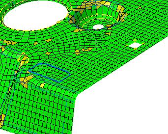
41 Page 41 Open the sample05.catanalysis document from the samples directory. Before You Begin Enter the smart surfacic triangle quadrangle mesher. For this, double-click Smart Surfacic Mesh.1 feature from the specification tree (below Nodes and Elements feature) and then click OK (Continue anyway?) in the warning box. Mesh the surface. For this, click the Mesh The Part icon. Quality Visualization Mode Color Meaning Green Used when the element will be solved by the solver without any problem. Yellow Used when the element will be solved by the solver with very few possible problems. Red Used when the element will be hardly properly solved. Colors Used for Edges and Vertices Open the sample05.catanalysis document from the samples directory. Before You Begin Enter the smart surfacic triangle quadrangle mesher. For this, double-click Smart Surfacic Mesh.1 feature from the specification tree (below Nodes and Elements feature) and then click OK (Continue anyway?) in the warning box. Mesh the surface. For this, click the Mesh The Part icon.


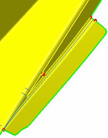
42 Page 42 Color Meaning Green Used for free edges and vertices, as well as holes. Yellow Used for edges/vertices that are shared between two constrained faces. Blue Used for edges/vertices that are shared between two non-constrained faces. Red Used for edges/vertices that are shared between more than two constrained faces. Miscellaneous
43 Page 43 Resuming Editing on Mesh Part Open the sample05.catanalysis document from the samples directory. Before You Begin Enter the smart surfacic triangle quadrangle mesher. For this, double-click Smart Surfacic Mesh.1 feature from the specification tree (below Nodes and Elements feature) and then click OK (Continue anyway?) in the warning box. Mesh the surface. For this, click the Mesh The Part icon. You can now exit the smart surfacic triangle quadrangle mesher, and then decide to resume editing. For this, by double-click on the Smart Surfacic Mesh.1 feature from the specification tree. A message will let you decide whether you want to edit the meshed CATAnalysis with: the initial meshing OR the meshing last created. Be careful: if the geometry was not properly updated, the CATAnalysis will be edited anyway with the initial meshing.

44 Beam Meshing Page 44 This task shows you how to add beam mesh to a Generative Shape Design CATPart, and if needed, edit the mesh. You can add a beam mesh on a Structure Design beam. So you will mesh it with 1D elements. You cannot add beam mesh to a sketch geometry. Open the sample47.catanalysis document from the sample directory. Before You Begin: Make sure a material was applied to the geometry, first. 1. Click the Beam Mesher icon. 2. Select the feature corresponding to the geometry to be associated a mesh part. The Beam Meshing dialog box appears. Element size: lets you set the global mesh size Edit Mesh...: lets you edit mesh manually to enhance quality Sag control: lets you set the element minimum size and sag. If checked, the corresponding values (Min size and Sag) appear in the dialog box Remember that the sag is the distance between the mesh elements and the geometry so that mesh refining is optimum in curve-type geometry:

45 Page 45 Element Type: lets you choose the 1D element type Linear: 1D element without intermediate node Parabolic: 1D element with an intermediate node 3. Enter the desired Element size in the Beam Meshing dialog box. In this example, enter a size of 20mm. 4. Click the Mesh button in the Beam Meshing dialog box to launch computation. The mesh is displayed. The Beam Meshing dialog box now appears as shown here: the Edit Mesh... button can be selected, if needed, to edit the mesh. 5. Select Linear or Parabolic as Element Type option and click the Mesh button in the Beam Meshing dialog box.

46 Page 46 Linear option activated Parabolic option activated 6. Click the Edit mesh button in the Beam Meshing dialog box. The Edit Mesh dialog box appears. Smooth: the neighbor elements are smoothed around the modified mesh. Node: Move node: move a node belong the geometry. Freeze node: fix a node whatever the modifications applied to the neighbor elements. Unfreeze node: cancel the Freeze node option. Edge: Split edge: create a node and split an edge into two edges. Condense edge: suppress an edge by condensation of one node and the node opposite to the point on the selected edge. 7. Activate the Sag control option in the Beam Meshing dialog box and modify the Min size and Sag values so that the mesh is refined as desired. Selected Size and Sag values Resulting mesh Selected Size and Sag values Resulting mesh
47 Page 47 Selected Size and Sag values Resulting mesh Moving a node: 8. Select the Move node option in the Node combo box. 9. Select a node and move it to the desired location. Select the node Move the node The result is: Smooth option deactivated Smooth option activated Splitting an edge: 10. Select the Split edge option in the Edge combo box. To refine the mesh, you need to check the Smooth option in the Edit Mesh dialog box. The neighbor edges are updated. 11. Select the edge you want to split.
48 Page 48 The result is: Smooth option deactivated Smooth option activated 12. Click OK in the Edit mesh dialog box. 13. Click OK in the Beam Meshing dialog box. The 1D Mesh.1 feature now appears in the specification tree. 1D, or beam mesh, can be deleted and/or added to parts manually.
49 Page 49 Surface Meshing This section deals with the 2D meshing methods. Meshing using OCTREE Triangle: Assign linear or parabolic triangle elements to a surface. Advanced Surface Mesher: Mesh a surface part and let you enter the Surface Meshing workshop.
50 Meshing Using OCTREE Triangles Page 50 This task will show you how to mesh a part using OCTREE triangles. Open the sample08.catanalysis document from the samples directory. 1. Click the Octree Triangle Mesher icon from the Meshing Methods toolbar. 2. Select the geometry to be meshed. For this, click either the geometry feature in the specification tree or click the part. The OCTREE Triangle Mesh dialog box appears. Global tab: Size: lets you choose the size of the elements. Absolute sag: maximal gap between the mesh and the geometry.

51 Page 51 Proportional sag: ratio between the Absolute sag and the local mesh edge length. Proportional sag value= (Absolute sag value) / (local mesh edge length value). Note that Proportional sag and Relative sag could modify the local mesh edge length value. You can use both Proportional sag and Relative sag, the most constraining of the two values will be used. Element type: lets you choose the type of element you want (Linear or Parabolic). Local tab: You can also add local meshing parameters such as sag, size or distribution to the part. For this select the desired Available specs and then click the Add button. Local size: you can modify the Name, Support and Value. Local sag: you can modify the Name, Support and Value. Edges distribution: lets you distribute local nodes on a edge. For this: Select the Edges distribution option and click Add. The Edges Distribution dialog box appears.


52 Page 52 Select the edge on which you want to assign nodes (Supports) as well as the Number of Edges to be created. The Edges Distribution.1 feature now appears in the specification tree. Click OK in the Local Mesh Distribution dialog box. In this particular case, 7 nodes are generated, i.e. 6 edges will be generated after the meshing. Imposed points: lets you select the points that will be taken into account when meshing. In this case, the points you have to select must have been created via Shape Design or Part Design. Only points on curve or points on surface are supported. The points support must be a member of the meshed geometry. For this: Select the Local imposed points option and click Add. The Imposed Points dialog box appears. Select from the specification tree (under Open Body feature) the points (Supports) you will impose for OCTREE triangle mesh generation. Click OK in the Imposed Points dialog box.
 to optimize the mesh quality.")
53 Page 53 To edit the local mesh distribution that has just been created, you need to double-click the Local Nodes Distribution object in the specification tree and modify the desired options from the Local Mesh Distribution dialog box that appears. Quality tab: Criteria: lets you choose a criterion (Shape, Skweness or Strech) to optimize the mesh quality. Intermediate nodes parameters: only available if you have chosen a Parabolic element type. This option lets you choose the position of parabolic tetrahedron intermediate nodes (Jacobian or Warp). The distance (d) between the geometry and the intermediate node is function of Jacobian and Warp values. For more details about mesh quality analysis, please refer to Analyzing Element Quality. Others tab: Details simplification: lets you remove small mesh. Geometry size limit: lets you specify the maximum size of the elements ignored by the mesher (before the meshing). If all the edges of a surface are smaller than the Geometry size limit value, this surface will be ignored by the mesher. Mesh edges suppression: removes small edges (after the meshing).

54 Page 54 Without Mesh edge suppression: With Mesh edge suppression: It may happen that Mesh edge suppression involve constraints violation. Global interior size: not available in Octree triangle mesh. Min. size for sag specs: lets you specify the minimum size of the mesh refining due to sags specifications. Max. number of attempts: lets you impose a maximum number of attempts, if several attempts are needed to succeed in meshing, in the case of a complex geometry. 3. Select the desired parameters in the OCTREE Tetrahedron Mesh dialog box. 4. Click Mesh in the OCTREE Triangle Mesh dialog box. The Computation Status dialog box appears. The OCTREE Triangle mesh is generated on the part. To edit the Octree triangle mesh, double-click the OCTREE Triangle Mesh.1 object in the specification tree. The OCTREE Triangle Mesh dialog box reappears.
55 Page 55 Advanced Surface Mesher This section shows you how to use the advanced surface mesher functionality and how to access the Surface Meshing workshop. 1. Enter the Surface Meshing workshop. 2. If needed, define local specifications of the surface mesher (using the Local Specifications toolbar). 3. Launch or remove the simplification geometry and/or the mesh (using the Execution toolbar). 4. If needed, perform manually modifications (using the Edition Tools toolbar). At any time, you can: a. access the global parameters if you want to visualize parameters you have defined or if you want to modify some of the global specifications. b. exit the Surface Meshing workshop.
56 Page 56 Entering the Surface Meshing Workshop This task shows you how to enter the Surface Meshing workshop by: creating a new mesh part (using the Advanced Surface Mesher functionality) editing an existing mesh part Creating a Mesh Part Open the sample06.catanalysis document from the samples directory. 1. Click the Advanced Surface Mesher icon. 2. Select the geometry to be meshed by clicking on the part. The Global Parameters dialog box appears.
57 Page 57 Element type: lets you specify if you want Linear or Parabolic elements. Mesh tab: Triangle Method Mesh size: global size assigned to the mesh. Offset: value according to which both the geometrical simplification and meshing will be offset. Absolute sag: maximal gap between the mesh and the geometry. Relative sag: ratio between the Absolute sag and the local mesh edge length. Relative sag value= (Absolute sag value) / (local mesh edge length value). Note that Absolute sag and Relative sag could modify the local mesh edge length value. You can use both Absolute sag and Relative sag, the most constraining of the two values will be used.
58 Page 58 Min size: minimum value of the mesh size. Only available when you want to use Absolute sag or Relative sag. Automatic mesh capture: when activated, mesh capture is performed dynamically on all the constraints (free edges, internal edges, external edges) and after all constraints modifications. You do not need to select all the constraints one after the others. Note that there is a capture tolerance, you can decide to impose or not a limitation to edge control neighborhood. Automatic capture is automatically performed using condensation. Meshing is then captured within the mesh part that belongs to the same CATAnalysis document, geometrically speaking. Be careful: mesh can only be captured on updated mesh part. Tolerance Quadrangle Method Mesh size: global size assigned to the mesh Offset: value according to which both the geometrical simplification and meshing will be offset Minimize triangles: minimum number of triangles in the mesh Directional mesh: produces a regular mesh based on a privileged direction of the domain. Strip optimization: optimization the nodes position along the strips Automatic mesh capture: when activated, mesh capture is performed dynamically on all the constraints (free edges, internal edges, external edges) and after all constraints modifications. You do not need to select all the constraints one after the others. Note that there is a capture tolerance, you can decide to impose or not a limitation to edge control neighborhood. Automatic capture is automatically performed using condensation. Meshing is then captured within the mesh part that belongs to the same CATAnalysis document, geometrically speaking. Be careful: mesh can only be captured on updated mesh part. Tolerance Geometry tab: Triangle and Quadrangle Methods Constraint sag: constraint is created along the edge of a face to avoid creating elements across this edge (the element sag would be higher than the specified value). This does not guarantee that the whole mesh respects the sag value but helps creating constraints. For a given mesh size, the lower the constraint sag value, the more numerous the constraints are created, and vice versa. For example: Due to the sag value (too high), the edges are not constrained (blue colored).
59 Page 59 Due to the sag value (low enough), the edges are constrained (yellow colored). Angle between faces: angle computed between the two normals corresponding to neighbor faces Angle between curves: angle computed between two tangents on a contour Min holes size: sets the diameter for automatic hole deletion Merge during simplification option: allows optimizing the position of the nodes in tight zones in order to improve the quality of the elements Min size Automatic curve capture: when activated, mesh capture is performed dynamically on all the constraints (free edges, internal edges, external edges) and after all constraints modifications. You do not need to select all the constraints one after the others. Note that there is a capture tolerance, you can decide to impose or not a limitation to edge control neighborhood. Automatic capture is automatically performed using condensation. Meshing is then captured within the mesh part that belongs to the same CATAnalysis document, geometrically speaking. Be careful: mesh can only be captured on updated mesh part. Tolerance 3. Select the desired parameters in the Global Parameters dialog box. The geometrical simplification is now launched. A Smart Surface Mesh object appears in the specification tree.

60 Page Click OK in the Global Parameters dialog box. You enter the Surface Meshing workshop. You can now: a. access the global parameters at any time, b. define local specifications of the surface mesher, c. launch the simplification geometry or the mesh execution, d. perform manually modifications, e. exit the Surface Meshing workshop at any time. Editing an Existing Mesh Part Open the Sample06.CATAnalysis document from the samples directory.

61 Page Update the Smart Surface Mesh.1 mesh part. For this, right-click the Smart Surface Mesh.1 mesh part and select the Update Mesh contextual menu. This will launch both the geometry simplification and the mesh execution. 2. Double-click the Smart Surface Mesh.1 mesh part in the specification tree. The Global Parameters dialog box appears. For more details about this dialog box, please click here. 3. Click OK in the Global Parameters dialog box without any modification. The following Warning message appears: 4. Click Yes in the Warning message. You enter the Surface Meshing workshop. You can now: a. access the global parameters at any time, b. define local specifications of the surface mesher, c. launch the simplification geometry or the mesh execution, d. perform manually modifications, e. exit the Surface Meshing workshop at any time. 5. Click the Remove Mesh icon and leave the Surface Meshing workshop.

62 Page 62 You return in the Advanced Meshing Tools workbench. 6. Double-click the Smart Surface Mesh.1 mesh part in the specification tree. The Global Parameters dialog box appears. 7. Click OK in the Global Parameters dialog box without any modification. The following Warning message appears: 8. Click Yes in the Warning message. You enter again the Surface Meshing workshop.
63 Page 63 Setting Global Meshing Parameters This task shows you how to visualize or modify the global meshing parameters at any time in the Surface Meshing workshop (before and after simplifying the geometry, before and after meshing). Open the sample06.catanalysis document from the samples directory. Enter the Surface Meshing workshop. For more details, please refer to Entering the Surface Meshing Workshop. 1. Click the Global Meshing Parameters icon from the Global Specifications toolbar. The Global Parameters dialog box appears.
64 Page 64 For more details about the description of the Global Parameters dialog box, please refer to Entering the Surface Meshing Workshop. 2. Change the desired parameters in the Global Parameters dialog box. 3. Click OK in the Global Parameters dialog box.
65 Page 65 Local Specifications Removing Holes: Ignore holes in the geometry. Removing Cracks: Ignore cracks in the geometry. Removing Faces: Ignore faces in the geometry. Adding/Removing Constraints (Specifications): Add or remove constraints applied to vertices or curves. Imposing Nodes (Specifications): Distribute nodes on edges. Specifying a domain: Impose a domain for the geometry simplification step.
66 Page 66 Removing Holes This task shows you how to ignore holes in the geometry which you consider as unnecessary holes. Open the Sample03.CATAnalysis document from the samples directory. Enter the Surface Meshing workshop. For more details, please refer to Entering the Surface Meshing Workshop. 1. Click the Boundary Simplifications icon from the Local Specifications toolbar. The Boundary Simplifications dialog box appears: Holes: Browse: browse the remaining holes Auto Focus: zoom in given holes. Cracks: please refer to Removing Cracks.

67 Page 67 Faces: please refer to Removing Faces. 2. Click a green hole. It is turned blue and will then be ignored by the mesher. 3. Click a blue hole. It is reactivated and will be taken into account by the mesher. The Boundary Simplifications dialog box is updated in accordance with the hole(s) you selected or de-selected:

68 Page Click the Mesh The Part icon. The meshed part now appears with ignored and non-ignored holes. 5. Click OK in the Mesh The Part dialog box.

69 Page 69 Removing Cracks This task shows you how to ignore cracks in the geometry. Open the Sample31.CATAnalysis document from the samples directory. Enter the Surface Meshing workshop. For more details, please refer to Entering the Surface Meshing Workshop. The CATAnalysis appears as shown here. 1. Click the Boundary Simplifications icon from the Local Specifications toolbar. The Boundary Simplifications dialog box appears: Holes: please refer to Removing Holes.

70 Page 70 Cracks: Browse: browse the remaining cracks Auto Focus: zoom in given cracks. Faces: please refer to Removing Faces. 2. Select the Cracks tab in the Boundary Simplifications dialog box. 3. Click the cracks to be removed. The Boundary Simplifications dialog box is updated accordingly: 4. Click OK in the Boundary Simplifications dialog box. You can now launch the Mesh operation. For this: 5. Click the Mesh the Part icon.

71 Page 71 The Mesh The Part dialog box appears. The boundary simplifications are taken into account. If needed, you can now apply manual simplifications. For this, click the Edit Simplification icon from the Edition Tools toolbar.

72 Page 72 Removing Faces This task shows how to ignore faces in the geometry. Open the Sample04.CATAnalysis document from the samples directory. Enter the Surface Meshing workshop. For more details, please refer to Entering the Surface Meshing Workshop. Mesh the part. For this, click the Mesh The Part icon You will then click OK in the Mesh The part dialog box. from the Execution toolbar. 1. Click the Boundary Simplifications icon from the Local Specifications toolbar. The Boundary Simplifications dialog box appears. You can configure the mesher to ignore faces and holes by simply clicking on these faces and holes. 2. Select the Faces tab in the Boundary Simplifications dialog box and then the faces to be removed from the model.

73 Page 73 The selected faces automatically appear in the Boundary Simplifications dialog box. 3. If needed, select the Holes tab in the Boundary Simplifications dialog box and then the hole to be removed from the model. The selected hole automatically appears in the Boundary Simplifications dialog
74 Page 74 box. Now, the faces and holes will be ignored by the mesher. 4. Click OK in the Boundary Simplifications dialog box. You can now launch the Mesh operation. For this, click the Mesh the Part icon.
75 Page 75
76 Page 76 Adding/Removing Constraints (Specifications) This task shows how to add/remove constraints as mesh specifications either using the geometry (curves or point) or directly on the geometrical simplification (edges or vertices). Adding/Removing Constraints (Specifications): On/From The Geometrical Simplification On/From The Geometry Using edge/external curve selection by path Two types of constraints exist: 1. a constraint applied to a vertex/point: as a result, a node will be created on this vertex. 2. a constraint applied to a edge/curve: as a result, all the element edges will be aligned on this curve. On/From The Geometrical Simplification Open the sample05.catanalysis document from the samples directory. Enter the Surface Meshing workshop. For more details, please refer to Entering the Surface Meshing Workshop. 1. Click the Add/Remove Constraints icon from the Local Specifications toolbar.
77 Page 77 The Add/Remove Constraints dialog box appears with tabs that will allow you assigning constraints to edges, vertices / curves, points. The Trap Type dialog box also appears and remains displayed as long as you keep the Edge tab active: You can use multi-selection: using an intersection polygon trap: all the domains which have non-empty intersection with the trap will be selected. using an inclusive polygon trap: all the domains that are completely included within the trap will be selected. 2. Select the edge which you want to constrain.


78 Page 78 Note that you can use edge selection by path. The Add/Remove Constraints dialog box now displays information on the element just selected. 3. Select the vertex which you want to constrain.

79 Page 79 The dialog box now displays information on the element just selected. If you select one element in this dialog box buttons become selectable: Remove: you can remove one constraint you previously created using this dialog box. Remove All: you can remove all the constraints you previously created using this dialog box. Zoom: you can zoom in on the constraint that is currently selected in this dialog box. 4. Click OK in the Add/Remove Constraints dialog box.
80 Page 80 On/From The Geometry Open the sample17.catanalysis document from the samples directory. Enter the Surface Meshing workshop. For more details, please refer to Entering the Surface Meshing Workshop. 1. Select the Add/Remove Constraints icon from the Local Specifications toolbar. The Add/Remove Constraints dialog box appears with tabs that will allow you assigning constraints to edges, vertices / curves, points. 2. Select the Curve tab in the Add/Remove Constraints dialog box and the desired geometry on the CATAnalysis document.
81 Page 81 Note that you can select the mono-dimension feature of a face or an edge. When selecting a face, the edges of the face are projected. For mono-dimension features (for example, intersection features), all the edges of the feature are projected. The Add/Remove Constraints dialog box now displays information on the elements just selected as well as the possibility to Capture Mesh edges from one curve to another. Note that you can use external curve selection by path. 3. Select more curves on the CATAnalysis document.
 a source curve edge. In other words, you will select both edges one after the other.")
82 Page 82 The dialog box is now as shown here: The Capture dialog box appears to let you select the destination curve edge and, if needed, (Show Sources button) a source curve edge. In other words, you will select both edges one after the other.
 Condensation: You can decide that the nodes from both edges (receiver and source)")
83 Page 83 Tolerance: Mesh will be found automatically relatively to the selected tolerance. Coincidence: You can decide that you will have the nodes from both edges superimposed (nodes created in coincidence) Condensation: You can decide that the nodes from both edges (receiver and source) are single nodes. The nodes of the source will be taken into account. Receivers: The edge on which the source will be projected. Show Sources: A switch that lets you select the curve to be projected onto the receiver. 4. Click Show Sources button in the Capture dialog box.

84 Page 84 You can now select the curve to be projected onto the receiver 5. Click OK in the Capture dialog box. 6. Click OK in the Add/Remove Constraints dialog box. 7. Mesh the surface. For this: click the Mesh The Part icon from the Local Specifications toolbar. You will then click OK in the Mesh The part dialog box. The part is meshed accordingly. Using Edge/External Curve Selection by Path
85 Page 85 Open the sample05.catanalysis document from the samples directory. Enter the Surface Meshing workshop. For more details, please refer to Entering the Surface Meshing Workshop. 1. Click the Add/Remove Constraints icon from the Local Specifications toolbar. The Add/Remove Constraints dialog box appears. 2. Go over an edge with the cursor. 3. Press the Shift key. The path corresponding to the edge you went over with the cursor is highlighted. 4. Choose the direction of the path by positioning the cursor on the path accordingly.

86 Page When you are satisfied with the operation, click on the path at the very point where you want the edge path to end. The edge path is defined.
, you need to force an update on")
87 Page 87 The Add/Remove Constraints dialog box is updated: Only updated mesh parts will be constrained. In others words, when you constrain the edge of a part, if you modify the associated geometry (external edges), you need to force an update on this part to have this part up to date.
88 Page 88 Imposing Nodes (Specifications) This task shows how to impose nodes (as mesh specifications) either on free edges or on constrained edges. Distribute nodes Capture nodes Mesh around holes Open the sample07.catanalysis document from the samples directory. Enter the Surface Meshing workshop. For more details, please refer to Entering the Surface Meshing Workshop. 1. Click the Imposed Elements icon from the Local Specifications toolbar. The Imposed Elements dialog box appears. Distribute Nodes This Imposed Elements dialog box will display information on the nodes you are going to distribute. Nodes can be distributed both on external and internal curves.


89 Page 89 Note that you can use edge selection by path. 2. Select the geometry on which you want to distribute nodes. You can select several edges on the condition they are continuous to each others. The Edit Elements Distribution dialog box now appears with given default values. Distribution type: Uniform: the distance between all the distributed nodes will be the same. Arithmetic: the distance between the distributed nodes will be defined by a common difference computed with the following parameters. Note that you have to specify two and only two parameters among the four. Number of Edges: lets you specify how many edges you want. Size 2 / Size 1: lets you specify the ratio between the lengths of the
90 Page 90 last and the first distribution edge. Size at node 1: lets you specify the length of the first edge of the distribution. Size at node 2: lets you specify the length of the last edge of the distribution. Geometric: the distance between the distributed nodes will be defined by a common ratio computed with the following parameters. Note that you have to specify two and only two parameters among the four. Number of Edges: lets you specify how many edges you want. Size 2 / Size 1: lets you specify the ratio between the lengths of the last and the first distribution edge. Size at node 1: lets you specify the distance between the two first nodes of the distribution. Size at node 2: lets you specify the distance between the two last nodes of the distribution. Selected element(s): multi selection is available Number of elements: check this option to define the number of the nodes you want to distribute on the currently selected geometry. Size: check this option to define the size on which a given nodes will be uniformly distributed. 3. If needed, modify the number of the nodes or size. In this case, enter 3 as new value (Number of elements).

91 Page Click OK in the Edit Elements Distribution dialog box. The nodes appear on the geometry. The Imposed Elements dialog box is automatically updated.

92 Page 92 If you select one element in this dialog box switch buttons become selectable: Edit: you can display the Edit Elements Distribution dialog box and, if needed, modify the values. Remove: you can remove one node distribution you previously created using this dialog box. Remove All: you can remove all the node distributions you previously created using this dialog box. Zoom: you can zoom in on the node distribution that is currently selected in this dialog box. The new nodes appear on the geometry which is automatically re-meshed.
93 Page Click OK in the Imposed Elements dialog box once you are satisfied with you operations. Capture Nodes Open the sample30.catanalysis document from the samples directory. Enter the Surface Meshing workshop. For more details, please refer to Entering the Surface Meshing Workshop. 1. Select the Capture tab in the Imposed Elements dialog box and the edge you want to be imposed nodes (also called Receiver edge).

94 Page 94 The Capture dialog box now appears as shown here: Note that you can use edge selection by path. Tolerance: The source edge will be found automatically relatively to the selected tolerance. Coincidence:
95 Page 95 You can decide that you will have the nodes from both edges superimposed Condensation: You can decide that the nodes from both edges (receiver and source) are single nodes. Receivers: The edge on which the source will be projected. Show Sources: A switch that let's you select the mesh edges to be projected onto the receiver. Be careful: mesh can only be captured on updated mesh part. 2. Enter the desired Tolerance value, for example 5mm, and click OK or Apply from the Capture dialog box. The nodes from a source edge at a 5mm from the receiver edge now appear.

96 Page 96 You might also decide that you want to explicitly select the source edge. For this: 3. Click the Show Sources switch button in the Capture dialog box. 4. Click in the Sources field with the mouse and then select the desired edge on the model. The Capture dialog box now appears as shown here:

97 Page 97 The nodes from the selected source edge now appear on the receiver edge. 5. Click OK in the Capture dialog box 6. Click OK in the Imposed Elements dialog box once you are satisfied with you operations. Mesh around Holes

98 Page 98 Open the sample07.catanalysis document from the samples directory. Enter the Surface Meshing workshop. For more details, please refer to Entering the Surface Meshing Workshop. 1. Select the Mesh around Holes tab and the hole you want to be imposed nodes. Note that whatever the number of curves making out the holes, multi-selection is automatic. you do not need to select each curve making out the hole.

99 Page 99 The Mesh Around Holes dialog box now appears. 2. Enter the desired number of elements in the Mesh Around Holes dialog box, if needed. Note that you can specify the height of the row, if needed. 3. Click OK in the Mesh Around Holes dialog box. Both the Imposed Elements dialog box and the model are updated.

100 Page 100 Hole and Nodes Before Hole and Nodes After: 4. Click OK in the Imposed Elements dialog box once you are satisfied with you operations.

101 Page 101 Specifying a Domain This task shows you how to impose a domain for the geometry simplification step. Open the sample08.catanalysis document from the samples directory. Enter the Surface Meshing workshop. For more details, please refer to Entering the Surface Meshing Workshop. In this particular example, choose the Frontal Quadrangles method and enter 10mm as Mesh size value. 1. Click the Domain Specifications icon from the Local Specifications toolbar. The Domain Specifications dialog box appears. Edit: lets you modify a domain specification. Remove: lets you remove a domain specification. Remove all: lets you remove all the domain specifications. 2. Select a domain as shown below.


102 Page 102 The Mesh Specification dialog box appears. Method: lets you specify the meshing method you want for this domain Mesh Size: lets you specify the mesh size value for this domain Remove: lets you remove an element of the selection Remove All: lets you remove all the elements of the selection. In this particular case: select Frontal Tria as Method option enter 15mm as Mesh Size value. 3. Select a continuous domain as shown below.

103 Page 103 The Mesh Specification dialog box is updated. Note that you cannot define a discontinuous domain. 4. Click OK in the Mesh Specification dialog box.

104 Page 104 The Domain Specifications dialog box is updated as shown below: 5. Click OK in the Domain Specifications dialog box. A Domain Specifications.1 object appears in the specification tree: 6. Click the Mesh the Part icon from the Execution toolbar. The part is meshed as shown below: 7. Edit the domain specification.
105 Page 105 For this: click the Remove Simplification icon from the Execution toolbar to remove the geometrical simplification click the Domain Specifications icon from the Local Specifications toolbar. The Domain Specifications dialog box appears. 8. Click the Edit button from the Domain Specifications dialog box. The Mesh Specification dialog box appears. 9. Select Frontal Quad as Method option from the Mesh Specification dialog box and click OK.

106 Page 106 The Domain Specifications dialog box appears and is updated as shown here: 10. Click OK in the Domain Specifications dialog box. 11. Click the Mesh the Part icon from the Execution toolbar. The mesh part is updated as shown below:


107 Page 107 Modifying Local Specifications with Knowledgeware This task shows you how to modify local specifications using the knowledge formula functionality. Open the sample07.catanalysis document from the samples directory. Enter the Surface Meshing workshop. For more details, please refer to Entering the Surface Meshing Workshop. 1. Click the Imposed Elements icon from the Local Specifications toolbar. 2. Select an edge as shown bellow: 3. Enter 5 as Number of elements in the Edit Elements Distribution dialog box. 4. Click OK in the Edit Elements Distribution dialog box and then in the Imposed Elements dialog box. The imposed nodes are displayed: 5. Click the Exit icon. 6. Click the Formula icon from the Knowledge toolbar. The Formulas: Analysis Manager dialog box appears. For more details about the Formula functionality and the Formulas dialog box, please refer to Formulas in the Infrastructure User's Guide. 7. Select the local specification you want to modify.
108 Page 108 In this particular example, select the Imposed Elements.1 specification. The Formulas dialog box is updated. 8. Select the second line. 9. Enter 10 as new value as shown bellow:

109 Page Click OK in the Formulas: Imposed Elements.1 dialog box. 11. Enter again the Surface Meshing workshop. Note that the number of element has been increased:
110 Page 110 Execution Simplifying the Geometry (Specification): Improve the meshing. Removing the Geometrical Simplification: Remove the geometrical simplification you applied to geometry. Meshing the Part: Launch the surface mesher execution. Removing the Mesh: Remove the mesh you generated on the geometry.
111 Page 111 Simplifying the Geometry This task shows how to simplify the geometry in order to improve the quality of the mesh. Open the sample05.catanalysis document from the samples directory. Enter the Surface Meshing workshop. For more details, please refer to Entering the Surface Meshing Workshop. 1. Click the Global Meshing Parameters icon. The Global Parameters dialog box appears.
112 Page Select the desired parameters and click OK in the Global Parameters dialog box. For more details about this dialog box, please refer to Setting Global Meshing Parameters. 3. Click the Geometry Simplification icon from the Execution toolbar. A set of optimized constraints is computed.
113 Page 113 Geometrical simplification is always done, before meshing, even if you do not launch it. determine if you have to modify manually the specifications before the meshing. Simplify the geometry to preview the domains. If needed, modify the specifications: Remove the geometrical simplification. For more information, please refer to Removing the Geometrical Simplification. Define the desired specifications. For more information, please refer to Local Specifications toolbar.
114 Page 114 Removing the Geometrical Simplification This task shows how to remove the geometrical simplification you applied to geometry. The mesh elements also are removed. Open the sample08.catanalysis document from the samples directory. Enter the Surface Meshing workshop. For more details, please refer to Entering the Surface Meshing Workshop. Launch the geometrical simplification. For more details, please refer to Simplifying the Geometry. 1. Click the Remove Simplification icon from the Execution toolbar.
115 Page 115 The geometrical simplification is automatically removed after you confirmed the operation in a box that appears.
116 Page 116 Meshing the Part This task demonstrates how to launch the mesh of a surface part. FEM Surface lets you automatically handle the mesh of complex geometries with advanced control on specifications. The meshes are fully associative with design changes. You can define specifications in order to simplify the geometry. However, the referenced geometry is never modified in the whole meshing process. The mesh deals with the exact replica of the geometry as a clone: it respects all the geometry characteristics, and adapt those to the mesh needs, without impacting the original geometry design. You get an automatic simplified interpretation of the meshed geometry. For example, you can mesh over holes and gaps. In the same way, it is possible to eliminate small faces such as stiffeners or flanges for meshing. You can achieve an accurate and smart elimination of details such as fillets. Different types o f finite elements and meshing methods are available: quadrangles or triangles, advancing-front or mapped meshers. Open the sample08.catanalysis document from the samples directory. Enter the Surface Meshing workshop. For more details, please refer to Entering the Surface Meshing Workshop. Constraints and nodes appear.
117 Page Click the Mesh The Part icon from the Execution toolbar. The mesh is generated on the part. A little summary is provided in the Mesh The Part dialog box. 2. Click OK in the Mesh The Part dialog box. Any modification you will then manually apply to the meshed surface will not be saved for example if you edit the mesh. In other words, each time you will apply manual modifications (Adding/Removing Constraints (Modifications), Imposing Nodes (Modifications), Re-meshing Domains, Mesh Editing), these modifications will only be saved on the condition you launch the mesh operation again.
118 Page 118 Removing the Mesh This task shows how to remove the mesh you generated on the geometry. Open the sample08.catanalysis document from the samples directory. Enter the Surface Meshing workshop. For more details, please refer to Entering the Surface Meshing Workshop. Mesh the surface. For more details, please refer to Meshing the Part. 1. Click the Remove Mesh icon from the Execution toolbar. The mesh is automatically removed.
119 Page 119
120 Page 120 Edition Tools Cleaning Holes: Ignore holes in the mesh. Adding/Removing Constraints (Modifications): Add or remove two types of constraints: constraints applied to vertices ; constraints applied to curves. Imposing Nodes (Modifications): Distribute nodes on edges. Domain Edition Re-meshing a Domain: Re-mesh a domain using new parameters. Removing the Mesh by Domain: Remove the mesh you generated on a domain of the geometry. Locking a Domain: Lock a domain by selecting it. Modify Mesh Mesh Editing: Edit a mesh to provide higher quality. Splitting Quadrangles: Split quadrangle elements in order to improve the mesh quality.
121 Page 121 Cleaning Holes This task shows you how to specify manually which hole you want to ignore during the mesh process. Open the Sample03.CATAnalysis document from the samples directory. Enter the Surface Meshing workshop. For more details, please refer to Entering the Surface Meshing Workshop. Mesh the surface. For more details, please refer to Meshing the Part. Hide the geometry for a better visualization of the mesh. For this, right-click the Part.1 in the specification tree and select the Hide/Show contextual menu. 1. Click the Clean Holes icon from the Edition Tools toolbar. The Boundary Simplifications dialog box appears: Auto remesh on modification: if you activate this option, an automatic re-mesh is performed on the domain. if you deactivate this option, the mesh will be removed on the domain. 2. Select the Auto remesh on modification option in the Clean Holes dialog box. 3. Select a hole as shown bellow.
122 Page 122 As a result, an automatic re-mesh is performed around the selected hole: 4. Select a hole as shown bellow.
123 Page 123 As a result, an automatic re-mesh is performed around the selected hole: 5. Select the Auto remesh on modification option in the Clean Holes dialog box. 6. Select a hole as shown bellow.


124 Page 124 As a result, the mesh is removed on the domain: 7. Click the Mesh the Part icon from the Execution toolbar.
125 Page 125 As a result the meshing process is launched and all the modifications you have previously performed are taken into account. 8. Click OK in the Mesh The Part dialog box. 9. Click again the Clean Holes icon from the Edition Tools toolbar.
126 Page 126 Adding/Removing Constraints (Modifications) This task shows how to apply manual topological modifications on existing constraints. There are two types of constraints. 1. a constraint applied to a vertex: as a result, a node will be created on this vertex. 2. a constraint applied to a curve: as a result, all the element edges will be aligned on this curve. Adding/Removing Constraints using: Swap constrained state option Split a domain option Collapse edge option Cut edge option Merge edges option Undo simplifications option Drag option Open the sample05.catanalysis document from the samples directory. Enter the Surface Meshing workshop. For more details, please refer to Entering the Surface Meshing Workshop. Launch the geometrical simplification. For more details, please refer to Simplifying the Geometry.

127 Page Click the Edit Simplification icon from the Edition Tools toolbar. The Edit Simplification dialog box appears with one option for re-meshing automatically as you modify the geometrical simplification. The Undo command is not available. 2. Right-click the elements required for modifying edges, vertices or still for performing split, collapse or merge operations. 3. Select the desired options from the available contextual menu. For edges: For vertices: The desired option (contextual menu), once selected, remains active. You then simply need to select the elements to be modified. Swap constrained state option

128 Page 128 If you right-click on this part: You get this constrained state edge: Split a domain option If you right-click on two existing vertices: You get this split domain: Collapse edge option If you right-click on an edge: You get this collapsed-edge element:

129 Page 129 I Cut edge option If you right-click on an edge: You get this cut edge (and new vertex): Merge edges option If you right-click on two collapsed edges: One after the other: You get this merged edge:
.")
130 Page 130 I Drag option If you right-click on a vertex on a constrained edge You can move the vertex over the constrained edge: I Undo simplifications option This option can be applied either on simplifications generated by the system or on simplifications you applied manually (see above). If you right-click on an edge: You get this unmerged mesh element:
131 Page 131

132 Page 132 Imposing Nodes (Modifications) This task shows how to impose node distribution on geometry. Open the sample08_1.catanalysis document from the samples directory. Enter the Surface Meshing workshop. For more details, please refer to Entering the Surface Meshing Workshop. Mesh the surface. For more details, please refer to Meshing the Part. Display the geometry in shading mode. For this, click the Shading (SHD) icon from the View toolbar. 1. Click the Imposed Elements icon from the Edition Tools toolbar. The Imposed Elements dialog box appears. The Undo command is not available. Note That you can now edit the nodes distribution done before the meshing. For more information on the Edit Elements Distribution dialog box, please refer to Imposing Nodes (Specifications).
.")
133 Page Select the geometry on which you want to modify nodes distribution. The Edit Elements Distribution dialog box now appears with default values corresponding to the edge you just selected. 3. Modify the number of the nodes. In this case, enter 2 as new value (Number of elements). For more information about the Edit Elements Distribution dialog box, please refer to Imposing Nodes (Specifications). 4. Click OK in the Edit Elements Distribution dialog box. 5. In the Imposed Elements dialog box, activate the Auto remesh on modification option and click OK.
134 Page 134 The new nodes appear on the geometry which is automatically re-meshed.
135 Page 135 Re-meshing a Domain This task shows how to re-mesh a domain using new specifications such as mesh method and size. You will see here only three particular mesh methods: mapped quads projection mapping Mapped Quads Mesh Method Open the sample22.catanalysis document from the samples directory. Enter the Surface Meshing workshop. For more details, please refer to Entering the Surface Meshing Workshop.

136 Page Click the Remesh Domain icon in the Edition Tools toolbar. The Remesh Domain dialog box appears. Mesh method: Front quads ( * ) Front trias ( * ) Mapped quads Mapped trias Mapped Free quads Bead quads
137 Page 137 Half Bead quads Projection Mapping ( * ) ( * ) indicates that the Trap Type dialog box appears at the same time you choose the option. You can use multi-selection: using an intersection polygon trap: all the domains which have nonempty intersection with the trap will be selected. using an inclusive polygon trap: all the domains that are completely included within the trap will be selected. Impact neighbor domains: lets you define whether you wish to apply the new mesh method to the neighboring domains. If the option is de-activated, the nodes on domain edges will not be modified. Smooth projected mesh: allows you to optimize the quality of the projected mesh (this option is only available with the Projection and the Mapping options). Mesh size: lets you enter the desired mesh size (this option is not available with the Projection and the Mapping options). 2. Select the Mapped quads option in the Remesh Domain dialog box.
")

138 Page Select the desired domain on the surface. The edge of the selected domain can be either green (constrained) or yellow (free). 4. Enter the desired Mesh size value. In this particular example, enter 15mm. 5. Click Apply in the Remesh Domain dialog box.
139 Page 139 The selected domain is re-meshed. You can see that the corners (C0, C1, C2 and C3) of the domain are displayed. You can select a corner and change its position by clicking another vertex. 6. Click Close in the Remesh Domain dialog box. Note that: you can remove the mesh if you are not satisfied. For more details, please refer to Removing the Mesh. Projection Mesh Method All the mesh elements are projected on the receiving domain and the projected mesh respects the initial mesh topology. The projection mesh method automatically makes the correspondence between vertex and node (by projecting a vertex on a node).
 must have the same number of boundaries. In the following example: you can project the mesh of the domain A to the domain C.")
140 Page 140 Open the sample22_1.catanalysis document from the samples directory. Enter the Surface Meshing workshop. For more details, please refer to Entering the Surface Meshing Workshop. The two domains (the meshed one and the receiving one) must have the same number of boundaries. In the following example: you can project the mesh of the domain A to the domain C. you cannot project the mesh of the domain A to the domain B. If you try to do this, an error message appears to inform you that the number of boundaries of the two domains is different.


141 Page Click the Remesh Domain icon in the Edition Tools toolbar. The Remesh Domain dialog box appears. For more details about this dialog box, please refer to Mapped Quads Mesh Method. 2. Select the Projection option in the Remesh Domain dialog box. 3. Select the domain you want to mesh. The meshed domain must be towards the receiving domain. 4. Select the mesh domain. 5. Click OK in the Remesh Domain dialog box.


142 Page 142 The projected domain is updated. The projected mesh entirely fills the receiving domain. The projected mesh is not partial. The only way to preserve the mesh elements size between the meshed domain and the receiving domain is to modify the receiving domain (by splitting it, for example)
143 Page 143 Mapping Mesh Method All the mesh elements are projected on the receiving domain and the projected mesh respects the initial mesh topology. Contrary to the projection mesh method, you have to define the correspondence between vertex and node in case of mapping mesh method. Open the sample22.catanalysis document from the samples directory. Enter the Surface Meshing workshop. For more details, please refer to Entering the Surface Meshing Workshop. The two domains (the meshed one and the receiving one) must have the same number of boundaries. In the following example: you can project the mesh of the domain A to the domain C. you cannot project the mesh of the domain A to the domain B. If you try to do this, an error message appears to inform you that the number of boundaries of the two domains is different.

144 Page Click the Remesh Domain icon in the Edition Tools toolbar. The Remesh Domain dialog box appears. For more details about this dialog box, please refer to Mapped Quads Mesh Method. 2. Select the Mapped Quads option in the Remesh Domain dialog box. Multi-selection is not available. 3. Select the desired domain. 4. Enter the desired Mesh size value. In this particular example, enter 15mm. 5. Click OK in the Remesh Domain dialog box. 6. Click the Remesh Domain icon in the Modification Tools toolbar. 7. Select the Mapping option in the Remesh Domain dialog box. 8. Select the domain you want to mesh.

145 Page 145 The Trap Type dialog box appears. For more details about this diolog box, please refer to Mapped Quads Mesh Method. Multi-selection is available on the condition you multi-select connected mesh domains. 9. Select the meshed domain to be projected on the previously selected domain. 10. Select a vertex on the domain that will receive the projected mesh to identify it with the nearest node of the mesh domain. You now have to set up all the needed correspondence between vertex (of the domain to be meshed) and the nodes (of the mesh domain). 11. Select the corresponding node on the mesh domain.


146 Page 146 As soon as you have selected the node, the geometry appears as shown here: You can see that some vertex are not corresponding with nodes of the mesh domain. You can manually establish the correspondence. For this, select a vertex and then the corresponding node on the mesh domain. 12. Click OK in the Remesh Domain dialog box.

147 Page 147 The mapped domain is updated as shown here:
148 Page 148 Removing the Mesh by Domain This task shows how to remove the mesh you generated on a single or several domains of the geometry. Open the sample08.catanalysis document from the samples directory. Enter the Surface Meshing workshop. For more details, please refer to Entering the Surface Meshing Workshop. Mesh the surface. For more details, please refer to Meshing the Part. 1. Click the Remove Mesh by Domain icon from the Edition Tools toolbar to activate the remove mesh by domain mode. The Trap Type dialog box appears. 2. Select the mesh of the single domain or domains you want to remove.
149 Page 149 For this You can use: Mono selection to select a single domain Multi-selection using the Trap Type dialog box using an intersection polygon trap: all the domains which have non-empty intersection with the trap will be selected. using an inclusive polygon trap: all the domains that are completely included within the trap will be selected. In this particular case click a domain as shown below: As a result the mesh of the selected domain is removed: 3. Click the Remove Mesh by Domain icon from the Edition Tools toolbar to deactivate the remove mesh by domain mode.
150 Page 150 The Trap Type dialog box disappears. Note that removing the mesh by domain is useful before Re-meshing a Domain. You can improve the mesh of a domain without removing the mesh of all the part.
151 Page 151 Locking a Domain This task shows how to lock a domain. Open the sample05.catanalysis document from the samples directory. Enter the Surface Meshing workshop. For more details, please refer to Entering the Surface Meshing Workshop. Mesh the surface. For more details, please refer to Meshing the Part. 1. Select the Lock Domain icon from the Edition Tools toolbar. The Trap Type dialog box appears You can use multi-selection: using an intersection polygon trap: all the domains which have non-empty intersection with the trap will be selected. using an inclusive polygon trap: all the domains that are completely included within the trap will be selected. 2. Select the domain to be locked.
152 Page 152 This domain is now transparent: any modification applied to neighboring domain will not impact the locked domain. the locked domain cannot be re-meshed. If you select two domains which are not homogeneous, a warning box appears: Do you want to lock the selected domains? If you click No, the domains will be unlocked.
153 Mesh Editing Page 153 This task shows how to edit surface elements. Thanks to the full cursor editing, you can preview and then update dynamically the quality analysis results on the mesh. When quality criteria are respected, you will see the change in finite element color. You can also move nodes on geometry, edit finite elements (splitting, swapping, and so forth) or smooth the mesh. Mesh Editing on: Surface Elements Edges using either the Contextual menu or: Dynamic Update of Element Quality Analysis (colors change, if needed) Full Mouse Mesh Editing Automatic Smooth on Nodes Contextual Menu Open the sample05.catanalysis document from the samples directory. Enter the Surface Meshing workshop. For more details, please refer to Entering the Surface Meshing Workshop. Mesh the surface. For more details, please refer to Meshing the Part. 1. Click the Edit Mesh icon from the Edition Tools toolbar. The Edit Mesh dialog box appears. Smooth around modifications: allows optimizing the shape of the element so that split elements meet desired Analysis criteria: Note that as the Auto smooth option is inactive in the Edit Mesh dialog box, the surrounding elements are not modified and therefore do not enhance the quality whatever the modifications you perform. Smooth around modifications option activated (the shape of the neighbor elements is altered in order to have the best possible quality of the elements).
.")

154 Page 154 Smooth around modifications option de-activated (the shape of the neighbor elements is not altered) Combine around modifications: allows combining two triangles into a quadrangle of good quality (when possible). Combine around modifications option activated. Swap around modifications: allows dragging a node on a surface. Propagate to neighbour domains: allows propagating smoothing modifications from one domain to a neighboring one. Global Optimization: lets you launch again the Quality Analysis. Surface Elements


155 Page 155 Using the Contextual Menu You can split or condense elements: 2. Position the Condense element symbol very close to a node and right-click. In this case, we de-activated all the options from the Edit Mesh dialog box. Target vs opposite node Condensed node Before After Dynamic Update of Element Quality Analysis (colors change, if needed) 3. Position the cursor over one quadrangle element.


156 Page 156 You can now cut the mesh element diagonally according to the position of the cursor. Before (quadrangle mesh) When you go over the quadrangle mesh you want to cut, both a symbol ( cut mesh preview appear on this mesh. After (cut mesh according to the position of the cursor) ) and orange-highlighted Full Mouse Mesh Editing You can drag nodes on surfaces 4. Select a node and move it to the desired location. The quality of the elements updates according to the location you assign to the node. Automatic Smooth on Nodes


157 Page 157 You can smooth elements by letting the algorithm update the mesh elements location. 5. Click on a node. The node is automatically moved to the optimum location. The quality of the elements updates according to this new location. Edges Contextual Menu 6. Right-click a segment. Once you selected an option from the contextual menu, when you go over the quadrangle mesh you want to edit, both the corresponding symbol and orange-highlighted edited mesh preview appear on this mesh. : allows removing edges you previously created manually when splitting a quadrangle element In this case, we activated all the options, right-clicked an edge and activated the Remove edge contextual menu. edge selected deleted edge


158 Page 158 : allows condensing nodes on edges or a node on another node. In this case, we activated all the options, right-clicked an edge and activated the Condense nodes contextual menu. edge selected condensed node In this new case, we de-activated all the options, positioned the Condense symbol very close to a node and right-clicked. : allows inserting a node on an edge In the case below, we de-activated the Auto combine and Auto swap options, right-clicked an edge and activated the Insert node contextual menu. edge selected inserted node In the case below, we activated the Auto combine options, right-clicked an edge and activated the Insert node contextual menu. edge selected inserted node


159 Page 159 : allows swapping between two edges. When you make a swap between a triangle and a quadrangle, whatever the edge new position, the resulting mesh will always be a triangle and a quadrangle. The preview will be a good help. Two Quadrangle Elements: edge selected swapped edge A Quadrangle and a Triangle: One TR/one QD before One TR/one QD after

160 Page 160 Splitting Quadrangles This task shows you how to improve the element quality by splitting the quadrangles. Open the Sample01_1.CATAnalysis document from the samples directory. Enter the Surface Meshing workshop. For more details, please refer to Entering the Surface Meshing Workshop. 1. Click the Split Quadrangles icon from the Edition Tools toolbar to activate the split quadrangles mode. The Split Quadrangles dialog box appears: Element quality: lets you specify the elements to split depending on their quality. You can choose Bad, Bad and poor, Poor and All elements qualities Element selection: lets you specify the elements to split depending on their
161 Page 161 location using the trap type elements selection method Do not use Element Selection parameter if you want to perform the split quadrangles functionality on all the mesh part. You have only to click on it. 2. Select Bad as Element quality option and click the mesh part. Bad quality elements are split, if necessary, in order to improve their quality as shown below: 3. Click the Undo icon from the Standard toolbar to undo your modifications, select Poor as Element quality option and click the mesh part. Poor quality elements are split, if necessary, in order to improve their quality as shown below:
162 Page Click the Undo icon from the Standard toolbar to undo your modifications, select Bad and poor as Element quality option and click the mesh part. Bad and poor quality elements are split, if necessary, in order to improve their quality as shown below: 5. Click the Undo icon from the Standard toolbar to undo your modifications, select All as Element quality option and click the mesh part.
163 Page 163 All quality elements are split, if necessary, in order to improve their quality as shown below: 6. Click OK in the Split quadrangles dialog box to deactivate the split quadrangles mode. Note that each selected element is split only if it will improve the mesh quality.
164 Leaving the Surface Meshing Workshop Page 164 This task shows you how to exit the Surface Meshing workshop. Open the sample06.catanalysis document from the samples directory. 1. Double-click the Smart Surface Mesh.1 in the specification tree. The Global Parameters dialog box appears. 2. Click OK in the Global Parameters dialog box. You now enter the Surface Meshing workshop: You can access the following toolbars: Global Specifications, Local Specifications, Execution and Edit Tools. At any time you can exit the Surface Meshing workshop. For this: 3. Click the Exit icon from the Exit toolbar.

165 Page 165 You retrieve the Advanced Meshing Tools workbench.
166 Page 166 Solid Meshing This section deals with the 3D meshing methods. OCTREE Tetrahedron Mesher: Assign linear or parabolic tetrahedrons elements to a solid. Tetrahedron filler: Mesh a solid part by generating tetrahedron meshes from surface meshes.
.")
167 OCTREE Tetrahedron Mesher Page 167 This task will show you how to mesh a solid part using the OCTREE Tetrahedron Mesher. Open the sample41.catanalysis document from the samples directory. 1. Click the Octree Tetrahedron Mesher icon from the Meshing Methods toolbar. 2. Select the solid you want to mesh. The OCTREE Tetrahedron Mesh dialog box appears. Global tab: Size: lets you choose the size of the elements (in mm). Absolute sag: maximal gap between the mesh and the geometry. Proportional sag: ratio between the Absolute sag and the local mesh edge length. Proportional sag value= (Absolute sag value) / (local mesh edge length value). Note that Proportional sag and Relative sag could modify the local mesh edge length value. You can use both Proportional sag and Relative sag, the most constraining of the two values will be used. Element type: lets you choose the type of element you want (Linear or Parabolic). Local tab: You can also add local meshing parameters such as sag, size or distribution to the part. For this select the desired Available specs and then click the Add button.

168 Page 168 Local size: you can modify the Name, Support and Value. Local sag: you can modify the Name, Support and Value. Edges distribution: lets you distribute local nodes on a edge. For this: Select the Edges distribution option and click Add. The Edges Distribution dialog box appears. Select the edge on which you want to assign nodes (Supports) as well as the Number of Edges to be created. The Edges Distribution.1 feature now appears in the specification tree as well as the nodes on the selected Edge. Click OK in the Local Mesh Distribution dialog box.
169 Page 169 Imposed points: lets you select the points that will be taken into account when meshing. In this case, the points you have to select must have been created via Shape Design or Part Design. Only points on curve or points on surface are supported. The points support must be a member of the meshed geometry. For this: Select the Local imposed points option and click Add. The Imposed Points dialog box appears. Select from the specification tree (under Open Body feature) the points (Supports) you will impose for OCTREE tetrahedron mesh generation. Click OK in the Imposed Points dialog box. To edit the local mesh distribution that has just been created, you need to double-click the Local Nodes Distribution object in the specification tree and modify the desired options from the Local Mesh Distribution dialog box that appears. Quality tab Criteria: lets you choose a criterion (Shape, Skweness or Strech) to optimize the mesh quality. Intermediate nodes parameters: only available if you have chosen a Parabolic element type. This option lets you choose the position of parabolic tetrahedron intermediate nodes (Jacobian or Warp). The distance (d) between the geometry and the intermediate node is function of Jacobian and Warp values. For more details about mesh quality analysis, please refer to Analyzing Element Quality.
.")
170 Page 170 Others tab: Details simplification: lets you remove small mesh. Geometry size limit: lets you specify the maximum size of the elements ignored by the mesher (before meshing). If all the edges of a surface are smaller than the Geometry size limit value, this surface will be ignored by the mesher. Mesh edges suppression: removes small edges (after meshing). Without Mesh edge suppression: With Mesh edge suppression: It may happen that Mesh edge suppression involve constraints violation. Global interior size: lets you specify the maximum interior size of the mesh. If the value of the Global interior size is smaller than the value of the Size, the value of the Size will be reduced to the value of the Global interior size. Min. size for sag specs: lets you specify the minimum size of the mesh refining due to sags specifications. Max. number of attempts: lets you impose a maximum number of attempts, if several attempts are needed to succeed in meshing, in the case of a complex geometry. 3. Select the desired parameters in the OCTREE Tetrahedron Mesh dialog box. In this particular example, preserve the default parameters. 4. Click Mesh in the OCTREE Tetrahedron Mesh dialog box.

171 Page 171 The Computation Status dialog box appears and the mesh is generated on the part. For a better visualization, hide the geometry. For this, right-click the Links Manager.1 object and select the Hide/Show contextual menu. The OCTREE Tetrahedron Mesh.1: Part.1 object appears in the specification tree. To edit the Octree tetrahedron mesh, double-click the OCTREE Tetrahedron Mesh.1: Part.1 object in the specification tree. The OCTREE Tetrahedron Mesh dialog box reappears.
172 Page 172 Tetrahedron Filler This task will show you how to mesh a solid part by generating tetrahedron meshes from surface meshes. The tetrahedron filler provides volume mesh (Linear Tetrahedron or Parabolic Tetrahedron - cf. Finite Element Reference Guide ) from surface mesh (Linear Triangle Shell or Linear Quadrangle - cf. Finite Element Reference Guide ). There are two necessary conditions to generate a solid mesh: Make sure that the mesh surface is closed in terms of connectivity. Make sure that the surface mesh has no intersection. For this, please refer to Checking Intersections / Interferences. Before You Begin: A surface mesh must exist and can be associated or not to a geometry. If the surface mesh is associated to a geometry, this geometry can be either a solid or a set of connected faces. Open the sample40.catanalysis document from the samples directory. In this particular example, a surface mesh has been already created. 1. Click the Tetrahedron Filler icon from the Meshing Methods toolbar. The Tetrahedron Filler dialog box appears.

173 Page 173 MeshParts Remove: lets you remove a selected mesh part. Remove all: lets you remove all the mesh parts. Element Type: lets you choose the type of solid mesh elements. They are independent of the surface mesh elements degree. Linear: elements without intermediate nodes, useful to fill a solid with only straight edges. Parabolic: elements with intermediate nodes on the geometry, useful to fill a solid with curve edges. Linear elements type: Parabolic elements type: Size progression: factor which lets you dilute the mesh elements inside the solid (if this factor is equal to one, the internal edge sizes are the sizes induced from the surface edge sizes). 2. Select the desired options.


174 Page 174 In this particular example, select the Smart Surface Mesh.2. The dialog box is updated: In the case of a set of connected surface meshes, you have to select different surface mesh part until the global surface mesh is closed (free edges appear in green while the global surface mesh is not closed). 3. Select the Element type option and the Size progression factor. In this particular example, select the Linear option and 2 as Size progression factor. 4. Click Mesh button in the Tetrahedron Filler dialog box. The corresponding quads are automatically split into two triangles using the shortest diagonal. This operation is only a preprocessing of Tetrahedron Filler: the original quads are preserved in the mesh model. The mesh is generated on the part and the Tetrahedron Filler Mesh.1 appears in the specification tree.

 contains elements with")
175 Page 175 You can visualize the solid mesh using the Cutting Plane functionality For this: Hide the surface mesh. For this, right-click the Smart Surface Mesh.2 object and select the Hide/Show contextual menu. Select the Cutting plane icon from the Quality Analysis toolbar. The Cutting Plane Definition dialog box appears. Select the Z options, click the Reverse button. Deactivate the Exact mesh cut option. For more details, please refer to Cutting Plane. When Parabolic Elements are chosen in the Tetrahedron Filler dialog box, the mesh provided (by clicking the Mesh button or by updating the Tetrahedron Filler mesh part) contains elements with intermediate nodes (parabolic tetrahedron). At the moment, those nodes are located in the middle of the corresponding linear tetrahedron edges (i.e. not always on the geometry).
176 Page 176 Import / Export Mesh Importing the Mesh: Import an existing mesh. Exporting the Mesh: Save the mesh into a bulk data file or CATIA V4 file.

177 Importing the Mesh Page 177 This task shows how to import one or more existing Surface meshes from a.dat document. 1. Select the Start -> Analysis -> Advanced Meshing Tools menu. The New Analysis Case dialog box appears. 2. Click OK in the New Analysis Case dialog box. 3. Click the Import Mesh icon from the Import/Export toolbar. The Import mesh dialog box appears. 4. Select the Sample11.dat document from the samples directory. Multi-selection is available in the Import mesh dialog box. 5. Click the Open button in the Import mesh dialog box.
178 Page 178 The imported mesh appears as shown here:
179 Exporting the Mesh Page 179 This task shows how to store a mesh with a new format. These formats can be either.model (CATIA V4 files) or.dat (Bulk data files)..model: all the connectivities (geometrical shapes) are transferred..dat: OCTREE (GPS/EST) and Surface mesh (FMS) parts are transferred. Open the Sample11.CATAnalysis document from the samples directory. 1. Click the Export Mesh icon from the Import/Export toolbar. The Save mesh as dialog box appears.
180 Page Enter the desired options in the dialog box: File name and Save as type. 3. Click the Save button in the Save mesh as dialog box. The mesh will now be exported as New_name.dat in the samples directory.
181 Page 181 Meshing Connections Meshing Spot Welding Connections: Mesh spot welds that were previously defined in the Generative Structural Analysis workbench. Meshing Seam Welding Connections: Mesh a Seam Welding Connection that was created between two parts.
182 Page 182 Meshing Spot Welding Connections This task shows how to mesh spot welding connections. You can mesh the following connections: Point Analysis Connection and Point Analysis Connection within one Part created in the Generative Structural Analysis workbench Joint created in the Body in White Fastening workbench (except for the joint created using the datum mode) Spot Welding Analysis Connection created before the V5R12 in the Analysis Connections workbench Connections Support Analysis Connections (from R12) Point Analysis Connection One or two Point Analysis Connection within one Part Body in White Fastener Connections Joint (containing or not hemming information) One or more Analysis Connections (before R12) Spot Welding Analysis Connection Two For more details about joint containing hemming information, please refer to the Automotive Body in White Fastening User's Guide - Creating Joint Bodies. Open the sample26.catanalysis document from the samples directory.

183 Page Click the Spot Welding Connections icon. The Spot Welding Connections dialog box appears. Welds modelling: Welds modelling Non compatible mesh Compatible mesh Beam Rigid Rigid-Spring-Rigid
184 Page 184 Spring-Rigid-Spring Hexahedron Replace existing weld connection meshes: allows you to select a weld spot connection that has been already associated to a mesh part. You must activate this option before selecting the weld spot connection. If not, a warning message informs you that the weld spot connection has been already meshed. Mesh Compatibility: Non compatible: lets you create nodes by orthogonal projection of the welding points on the two mesh parts. Compatible: lets you use existing nodes. The welding points must have been previously projected on the two mesh parts. For more details, please refer to Adding/Removing Constraints (Specifications). Additional Information: Maximal gap: lets you specify the radius value of a sphere which has the welding spot as center. It must be an intersection between each face and the solid thus defined. The value must be strictly positive. While the Maximal gap value is null, the OK and the Mesh buttons will be not available. If you update spot welding connections created before the V5R12 level without modifying them, the data used to mesh are the same as those used up to the V5R11 level. Errors could be generated (for example: the maximal gap value is too small). In this case, you have to edit the connection mesh and to increase the Maximal Gap value. Diameter: lets you specify the diameter of the hexahedron. This option is only available if you selected the Hexahedron and the Non compatible options. Failed if at least one spot is not connected: lets you stop the Update all meshes process. If this option is activated and if you use the Update all meshes contextual menu, only the meshes created before the weld spot connection mesh will be
185 Page 185 updated. 2. Select the connection you want to mesh in the specification tree. In this particular example, select the Point Analysis Connection.1 object in the specification tree (under the Analysis Connections Manager.1 set). The Spot Welding Connection dialog box is updated. 3. Set the desired parameters.
186 Page 186 In this particular example: select Beam as Welds modelling option select Non compatible as Mesh Compatibility option enter 2mm as Maximal gap value 4. Click Mesh in the Spot Welding Connections dialog box. Several errors are displayed in the specification tree under the Weld Spot Connection Mesh.1 object. You have to change the Maximal gap value. 5. Double-click the Weld Spot Connection Mesh.1 object in the specification tree to edit it. The Spot Welding Connections dialog box appears. 6. Enter 5mm as Maximal gap value and click Mesh in the Spot Welding Connections dialog box. The connection mesh is now correct.
187 Page 187 For a better visualization, you can change the mesh color using the Properties contextual menu. You can also hide the OCTREE Triangle Mesh.1 and OCTREE Triangle Mesh.2 using the Hide/Show contextual menu: 7. Change the weld spot connection mesh parameters. For this, double-click the Weld Spot Connection Mesh.1 object in the specification tree. The Spot Welding Connection dialog box appears. In this particular example: select Hexahedron as Welds modelling option enter 3mm as Diameter value click the Mesh button If you use the Hide/Show contextual menu to hide the OCTREE Triangle meshes, the result will be:
 Line Analysis Connection One or two Line Analysis Connection within one Part Body in White Fastener Connections Joint One or more Analysis")
188 Meshing Seam Welding Connections Page 188 This task shows how to mesh a Seam Welding Connection that was created between two parts. Seam weld can be defined as a wire frame (or 1D) feature. Connections Support Analysis Connections (from R12) Line Analysis Connection One or two Line Analysis Connection within one Part Body in White Fastener Connections Joint One or more Analysis Connections (before R12) Seam Weld Analysis Connection Two Open the sample26.catanalysis document from the sample directory. 1. Select the Seam Welding Connections icon. The Seam Welding Connections dialog box appears. Welds modelling: Welds modelling Non compatible mesh (default behavior)
189 Page 189 Contact Rigid Rigid-Spring-Rigid Spring-Rigid-Spring Shell Hexahedron Replace existing weld connection meshes: allows you to select a weld seam connection that has been already associated to a mesh part. You must activate this option before selecting the weld seam connection. If not, a warning message informs you that the weld seam connection has been already meshed. Mesh Compatibility: Non compatible: lets you create nodes by orthogonal projection of the seam on the two mesh parts. Compatible: lets you use existing nodes. The welding seams must have been previously projected on the two mesh parts. For more details, please refer to Adding/Removing Constraints (Specifications). Additional Information: Maximal gap: lets you specify the radius value of each sphere created along the welding seam. It must be an intersection between each face and the solid thus defined. The value must be strictly positive. While the Maximal gap value is null, the OK and the Mesh buttons will be not available. If you update seam welding connections created before the V5R12 level without modifying them, the data used to mesh are the same as those used up to the V5R11 level. Errors could be generated (for example: the maximal gap value is too small). In this case, you have to edit the connection mesh and to increase the Maximal Gap value. Step: lets you specify the mesh progression along the welding seam. Width: lets you specify the width of the hexahedron. This option is only available if you selected the Hexahedron option. Failed if at least one spot is not connected: lets you stop the Update all meshes process. If this option is activated and if you use the Update all meshes contextual menu, only the meshes created before the weld seam connection mesh will be updated. 2. Select the connection you want to mesh in the specification tree.

190 Page 190 In this particular example, select the Line Analysis Connection.1 object in the specification tree (under the Analysis Connection Manager set). 3. Set the desired parameters. In this particular example: select Contact as Welds modelling option select Non compatible as Mesh Compatibility option enter 3mm as Maximal gap value enter 5mm as Step value 4. Click Mesh in the Seam Welding Connections dialog box. A Weld Seam Connection Mesh.1 object is displayed in the specification tree. For a better visualization, you can change the mesh color using the Properties contextual menu. You can also hide the OCTREE Triangle Mesh.1 and OCTREE Triangle Mesh.2 using the Hide/Show contextual menu:


191 Page Double-click the Weld Seam Connection Mesh.1 object in the specification tree to edit it. The Seam Welding Connections dialog box appears. 6. Change the seam weld connection mesh parameters. In this particular example: select Hexahedron as Welds modelling option enter: 3mm as Maximal gap value 5mm as Step value 3mm as Width value 7. Click Mesh in the Seam Welding Connections dialog box. You can hide the OCTREE Triangle Mesh.1 and OCTREE Triangle Mesh.2 using the Hide/Show contextual menu:
192 Page 192 Quality Analysis The quality analysis tools are available at any time in the Advanced Meshing Tools workbench and the Surface Meshing workshop. Displaying Free Edges: Perform quick visualization of incompatible mesh Checking Intersections / Interferences: Check meshes to detect intersections and/or interferences. Switching to Standard/Quality Visualization Mode: Switch to element standard/quality visualization mode. Analyzing Element Quality: Analyze element quality, select and tune quality criteria. Cutting Plane: Cut plane visualization mode. Elements Orientation: Elements Orientation visualization mode. Returning Mesh Part Statistics: Return mesh part statistics dynamically (only available in the Surface Meshing workshop)

193 Page 193 Displaying Free Edges This task shows how to display the free edges of the mesh and thereby quickly visualize incompatible mesh. Open the Sample05.CATAnalysis document from the samples directory. The mesh elements are assigned green, yellow or red colors. For more information, please refer to Before You Begin. 1. Click the Free Edges icon. The free edges are automatically drawn in green and allow quickly checking mesh validity.
194 Page 194 Checking Intersections / Interferences This task shows how to check intersections / interferences on meshed 2D geometry (surface element). Intersection means standard geometrical intersection. Interference means that the elements generated are positioned beyond a given distance (or clearance). This let's you take into account the real width of the geometry when detecting interferences. You can use the sample05.catanalysis document from the samples directory. Before You Begin: You have to enter the Surface Meshing workshop. For this, double-click Smart Surface Mesh.1 feature from the specification tree (below Nodes and Elements feature) and then click YES (Continue anyway?) in the warning box. You have to mesh the surface. For this, click the Mesh The Part icon from the Execution toolbar. You will then click OK in the Mesh The Part dialog box. For more information, please refer to Surface Mesher.

195 Page Click the Intersections / Interferences icon in the Mesh Analysis Tools toolbar. The Interference Check dialog box appears. Clearance: lets you define the clearance from which you decide that an interference exists. Dynamic check: lets you modify the mesh and dynamically visualize the corresponding interferences. Number of elements: in intersection: in interference: Autofocus: lets you focus on interference area. Note that the Interference visualization mode is different. The Clearance field allows you defining the clearance from which you decide that an interference exists. The clearance maximum value should not be greater than the mesh size. Note that: If the value is equal to zero, only the existing intersections will be visualized. If the value is greater than zero, both the existing intersections and interferences will be visualized The Dynamic check field allows you modifying the mesh and dynamically visualize the corresponding interferences. 2. Enter the desired Clearance value in the Interference Check dialog box. In this particular example, enter 1mm.

196 Page Click Apply in the Interference Check dialog box. Information on the number of the intersection elements and interference elements automatically appears in the dialog box. Note that the Autofocus option is available. These intersection elements and interference elements also appear on the geometry: the red color is assigned to intersection elements. the pink color is assigned to interference elements. 4. Activate the Autofocus option and click Apply in the Interference Check dialog box.

197 Page 197 The first interference area is displayed: 5. Click the >> button to display an other area. 6. Click Close in the Interference Check dialog box. Note that if you need to visualize the intersection elements exclusively, use the Wireframe (NHR) visualization type as the command is still active.
198 Page 198 Switching to Standard/Quality Visualization Mode This task shows how to switch either to the Standard or Quality visualization mode. Open the Sample11.CATAnalysis document from the samples directory. The default visualization mode is the Standard Visualization mode. 1. Click the Quality Visualization icon in the Visu Mode toolbar. The CATAnalysis document now appears as shown here:
199 Page 199 The mesh elements are assigned green, yellow or red colors. For more information, please refer to Before You Begin.
200 Analyzing Element Quality Page 200 This task shows how to analyze the quality of the elements relatively to given criteria, on one or more parts. Open the Sample11.CATAnalysis document from the samples directory. The mesh elements are assigned green, yellow or red colors. For more details, please refer to Before You Begin. 1. Click the Quality Analysis icon in the Quality Analysis toolbar. The Quality Analysis dialog box appears for visualizing element quality in accordance with selected criteria. Note that each time you will modify the criteria list, you need to select the Apply button to have the below detailed information (Statistic, Report, Select, Worst element) as well as the Finite Element Model visualization updated. Select tab A filter that let you select the criteria you will use for element analysis. Clicking the Infos tab: switch button, you will get the below basic and advanced information about a given criterion.

 or bad (red color). You can Restore Defaults you previously entered.")
201 Page 201 Name: the name of the selected criterion. A drawing as well as a definition is also provided. Threshold: the values at which you decide the element is good (green color), poor (yellow color) or bad (red color). You can Restore Defaults you previously entered. Advanced tab A graphic is provided that illustrate the criteria normalized threshold.
 results from the interpolation of the quality with both the Poor and the Bad weight that can be customized.")

202 Page 202 Normalized thresholds: allows modulating the weight of a criterion. The computation of the normalized quality (criteria normalized function) results from the interpolation of the quality with both the Poor and the Bad weight that can be customized. You can Restore Defaults you previously entered. Import Criteria Lets you choose a criteria configuration from a predefined list. For more details about managing the Import Criteria predefined list, please refer to Quality. Export Criteria Lets you save a criteria configuration to a predefined directory. By default, there is no pre-defined directory. You have to customize the quality settings: you can use the Export Criteria option only if a default directory is defined in the Options dialog box. For more details about managing the Export Criteria default directory, please refer to Quality. Show Statistic Curves In this example, let's choose the Distortion tab: you use the arrow to visualize the stated percentage for a given element threshold. Note that the information displayed in the Statistic Curves box depends on the options you pre-defined in the Quality Analysis dialog box (Options tab).

203 Page 203 Show Quality Report If you activate this button, the Quality Report dialog box will give you access to quality or connectivity information. Quality tab Information on Good, Poor, Bad, Worst or Average statistic for all the previously selected criteria. Connectivities tab

")
204 Page 204 Information on the mesh elements number, type, node in the current Finite Element model: Analyse An Element You can also select one element have this element analyzed. For example: The Analyze Single box appears with the quality type (Good, Poor, Bad) and value for all the selected criteria assigned to this particular element.


205 Page 205 Worst Elements Browser The Worst Elements Browser dialog box appears. You just need to click the Next button to have the worst elements zoomed. Show single analysis window: the Single Analysis window of the current worst element remains displays and updates as you browse a Next element. AutoFocus on element: the worst browsed element is automatically auto focused. For example: 2. Select the desired criteria from the Quality Analysis dialog box. 3. Analyze the quality of the other mesh part.

206 Page 206 For this, right-click on the Smart Surface Mesh Part.2 feature in the specification tree and select the Analyze contextual menu. The Mesh Part dialog box now appears with details on Quality and Connectivity report for the selected part: 4. Simultaneously perform the operation on all the parts you want to analyze. You will open as many Mesh Part dialog boxes as desired. 5. Click OK in the Mesh Part when you are satisfied with the information. You can perform an independent check and validation for each part in an assembly.
207 Page 207 Cutting Plane This task will show you how to cut a surface or a solid mesh part. You have to hide the geometry. Open the sample40.catanalysis document from the samples directory. Before You Begin: Hide the geometry. For this, right-click Link Manager.1 in the specification tree and select the Hide/Show contextual menu. 1. Click the Cutting plane icon. The Cutting Plane Definition dialog box appears. X, Y, Z options: lets you select the normal of which the direction is the X, Y or Z axis Reverse: lets you reverse the cutting part Exact mesh cut: if this option is activated, you can cut the mesh exactly where you drag the cursor. If this option is not activated, the cutting follows the mesh elements. 2. Select the desired parameters. In this particular example, select Z option and click the Reverse button.
208 Page Select the section and drag the cursor to the desired position. With the same cursor displacement: Exact mesh cut activated Exact mesh cut not activated


209 Page 209 Displaying Elements Orientation This task shows you how to visualize the elements orientation according to the normal direction of the finite element. Open the Sample01.CATAnalysis document from the samples directory. 1. Click the Element Orientation icon from the Quality Analysis toolbar. The elements orientation appears as shown below. red color indicates the positive orientation dark blue color indicates the negative orientation The positive side supports the finite element normal. The generation ordering of the nodes determines which side of the element is the positive one and which is the negative one.
210 Page Click the Element Orientation icon from the Quality Analysis toolbar to exit the element orientation visualization mode.

211 Page 211 Returning Mesh Part Statistics This task shows how to return mesh part statistics dynamically. Open the sample03.catanalysis document from the samples directory. Before You Begin: Enter the smart surface triangle quadrangle mesher. For this, double-click Smart Surface Mesh.1 feature from the specification tree (below Nodes and Elements feature) and then click YES (Continue anyway?) in the warning box. Mesh the surface. For this, click the Mesh The Part icon from the Specification Tools toolbar. You will then click OK in the Mesh The Part dialog box. See Setting Global Parameters for more information on this step. 1. Click the Mesh Part Statistics icon from the Specification Tools toolbar. The Statistics dialog box appears. Elements: number of the mesh part triangle elements. : Mesh part triangle number and percentage : Mesh part poor element number and percentage

212 Page 212 : Mesh part bad element number and percentage 2. Modify the mesh. For this, click the Edit Mesh icon from the Modification Tools toolbar and start modifying the mesh. See Mesh Editing for more information on this step The Statistics dialog box is dynamically updated as you edit the mesh: You can keep the Statistics dialog box displayed as you perform modifications on the mesh, whatever, using the Modification Tools commands.
213 Page 213 Mesh Transformations Translation: Create a translation mesh part from a parent mesh part. Rotation: Create a rotation mesh part from a parent mesh part. Symmetry: Create a symmetry mesh part from a parent mesh part. Extrusion by Translation: Create an extrusion by translation mesh part from a parent mesh part. Extrusion by Rotation: Create an extrusion by rotation mesh part from a parent mesh part. Extrusion by Symmetry: Create an extrusion by symmetry mesh part from a parent mesh part.
214 Page 214 Translation This task shows how to create a translation mesh part from a parent mesh part. This transformation is available in case of 1D, 2D and 3D mesh parts. Open the Sample09.CATAnalysis document from the samples directory. All the mesh parts must have been updated before creating a translation mesh part. 1. Click the Translation Mesher icon. The Translation dialog box appears.
215 Page 215 MeshPart: lets you select the parent mesh part Translation Parameters Direction: lets you choose the direction of the translation Distance: lets you choose the value and the orientation of the translation (in millimeters) Capture: lets you capture the existing mesh No condensation: lets you decide to not condense the nodes of the transformed and the parent mesh part Condensation With The Parent Mesh Part: lets you condense the nodes of the transformed and the parent mesh part Tolerance: lets you specify the tolerance of the condensation Condensation With All Mesh Parts: lets you condense the nodes of the transformed mesh part and all the neighboring mesh parts Tolerance: lets you specify the tolerance of the condensation Note that: This transformation respects associativity. In other words, if a load is applied to the parent mesh part, the same load will be applied to the transformed mesh part. 2. Select the Smart Surface Mesh.2 object. 3. Select the desired direction.
216 Page Type the desired value of translation in the Distance field. In this particular case, enter 50mm. You have the possibility to enter a positive or negative value to define the orientation of the translation. 5. Select the No condensation option in the Translation dialog box. 6. Click the Mesh button in the Translation dialog box. A Translation Mesh.1 object appears in the specification tree and the translation mesh part is created. For a better visualization, select the Translation Mesh.1 object in the specification tree.

217 Page Edit the translation mesh. For this, double-click the Translation Mesh.1 object in the specification tree. The Translation dialog box appears. 8. Enter -50mm as Distance value and click Mesh in the Translation dialog box. As a result, the translation mesh part appears in the opposite direction. For a better visualization, select the Translation Mesh.1 object in the specification tree.

218 Page 218 Rotation This task shows you how to create a rotation mesh part from a parent mesh part. This transformation is available in case of 1D, 2D and 3D mesh parts. Open the Sample09.CATAnalysis document from the samples directory. All the mesh parts must have been updated before creating a rotation mesh part. 1. Click the Rotation Mesher icon. The Rotation dialog box appears.

219 Page 219 MeshPart: lets you select the parent mesh part Rotation Parameters Axis: lets you select the axis of rotation Angle: lets you select the angle of rotation (in degrees) Capture: lets you capture the existing mesh No condensation: lets you decide to not condense the nodes of the transformed and the parent mesh part Condensation With The Parent Mesh Part: lets you condense the nodes of the transformed and the parent mesh part Tolerance: lets you specify the tolerance of the condensation Condensation With All Mesh Parts: lets you condense the nodes of the transformed mesh part and all the neighboring mesh parts Tolerance: lets you specify the tolerance of the condensation Note that: This transformation respects associativity. In other words, if a load is applied to the parent mesh part, the same load will be applied to the transformed mesh part. 2. Select the Smart Surface Mesh.2 object. 3. Select the axis of rotation.
220 Page Enter the desired value of rotation angle. In this particular case, enter 90 deg as Angle value. You have the possibility to enter a positive or negative value to define the orientation of the rotation. 5. Select the No condensation option in the Rotation dialog box. 6. Click the Mesh button in the Rotation dialog box. A Rotation Mesh.1 object appears in the specification tree and the rotation mesh part is created. For a better visualization, select the Rotation Mesh.1 object in the specification tree.


221 Page Edit the rotation mesh part. For this, double-click the Rotation Mesh.1 object in the specification tree. The Rotation dialog box appears. 8. Enter -90 deg as Angle value and click Mesh in the Rotation dialog box. As a result, the rotation mesh appears in the opposite direction. For a better visualization, select the Rotation Mesh.1 object in the specification tree.

222 Page 222 Symmetry This task shows you how to create a symmetric mesh part from a parent mesh part. This transformation is available in case of 1D, 2D and 3D mesh parts. Open the Sample40.CATAnalysis document from the samples directory. All the mesh parts must have been updated before creating a symmetry mesh part. 1. Click the Symmetry Mesher icon. The Symmetry dialog box appears.
223 Page 223 MeshPart: lets you select the parent mesh part Symmetry Parameters Plane: lets you select the plane of symmetry Capture: lets you capture the existing mesh No condensation: lets you decide to not condense the nodes of the transformed and the parent mesh part Condensation With The Parent Mesh Part: lets you condense the nodes of the transformed and the parent mesh part Tolerance: lets you specify the tolerance of the condensation Condensation With All Mesh Parts: lets you condense the nodes of the transformed mesh part and all the neighboring mesh parts Tolerance: lets you specify the tolerance of the condensation Note that: This transformation respects associativity. In other words, if a load is applied to the parent mesh part, the same load will be applied to the transformed mesh part. 2. Select the Smart Surface Mesh.2 object. 3. Select the zx plane in the specification tree. 4. Select the No condensation option in the Symmetry dialog box. 5. Click the Mesh button in the Symmetry dialog box. A Symmetry Mesh.1 object appears in the specification tree and the symmetric mesh part is created. For a better visualization, select the Symmetry Mesh.1 object in the specification tree.

224 Page Verify the intersections. For this, click the Intersections / Interferences icon, choose mm as Clearance value and click Apply in the Interference Check dialog box. You can see that there are 120 elements in interference because the nodes of the symmetric mesh part and the parent mesh part have not been condensed. Click Close in the Interference Check dialog box. 7. Edit the symmetric mesh. For this, double-click the Symmetry Mesh.1 object in the specification tree. The Symmetry dialog box appears. 8. Select the Condensation With The Parent Mesh Part option. 9. Enter 1mm as Tolerance value. 10. Click Mesh in the Symmetry dialog box. The symmetric mesh seems to be identical to the previous one.

225 Page Verify the intersections. In this case, there is no element in interference because the nodes of the symmetric mesh part and the nodes of the parent mesh part have been condensed. Click Close in the Interference Check dialog box.
226 Page 226 Mesh Extrusion by Translation This task shows you how to extrude a mesh by translation. You will see here the two possibilities of the extrusion by translation: create a 2D mesh from a 1D mesh create a 3D mesh from a 2D mesh Create a 2D mesh from a 1D mesh Open the Sample10.CATAnalysis document from the samples directory. 1. Click the Extrude Mesher with Translation icon from the Mesh Transformations toolbar.
227 Page 227 The Extrusion dialog box appears: MeshPart: lets you specify the mesh to extrude. Transformation: Axis: lets you specify the direction of the extrusion. Length: lets you specify the length of the extrusion. Note that you can reverse the extrusion direction if you enter a negative Length. Distribution: Type: Indicate the node distribution type. Layers Number: lets you specify the number of layers you want. Note that this value determines the mesh size. For example, if the extrusion Length value is 30mm and the Layers number value is 6, the mesh size value will be : 30mm / 6 = 5mm. 2. Select the 1D Mesh.1 feature from the specification tree. 3. Specify the properties of the extrusion in the Extrusion dialog box.
228 Page 228 In this particular case: Select Line.9 as Axis as shown below: Enter 30mm as Length value Select Uniform as Type option Enter 6 as Layers number value 4. Click the Mesh button.
229 Page 229 An Extrusion Mesh with Translation.1 object appears in the specification tree and a 2D extrusion by translation mesh part is created. 5. Edit the 2D extrusion by translation mesh. For this, double-click on the Extrusion Mesh with Translation.1 object from the specification tree. The Extrusion dialog box appears. 6. Enter 50mm as Length value and click Mesh in the Extrusion dialog box. As a result the 2D extrusion by translation mesh part is updated as shown below:
230 Page 230 Create a 3D mesh from a 2D mesh Use the CATAnalysis document you have obtained at the end of the Create a 2D mesh from a 1D mesh scenario or open the Sample10_1.CATAnalysis document from the samples directory. 1. Click the Extrude Mesher with Translation icon from the Mesh Transformations toolbar. The Extrusion dialog box appears. For more information about the Extrusion dialog box please refer to Create a 2D mesh from a 1D mesh. 2. Click the 2D mesh you want to extrude.
231 Page Specify the properties of the extrusion in the Extrusion dialog box. In this particular case: Select Line.10 as Axis as shown below: Enter 60mm as Length value Select Uniform as Type option Enter 8 as Layers number value


232 Page Click the Mesh button. An Extrusion Mesh with Translation.2 object appears in the specification tree and a 3D extrusion by translation mesh part is created. 5. Edit the 3D extrusion by translation mesh. For this, double-click on the Extrusion Mesh with Translation.2 object from the specification tree. The Extrusion dialog box appears.
233 Page Click the Axis input field in the Extrusion dialog box. 7. Select Line.2 as Axis as shown below: 8. Click Mesh in the Extrusion dialog box.

234 Page 234 As a result the 3D extrusion by translation mesh part is updated as shown below:
235 Page 235 Mesh Extrusion by Rotation This task shows you how to extrude a mesh by rotation. You will see here the two possibilities of the extrusion by rotation: create a 2D mesh from a 1D mesh create a 3D mesh from a 2D mesh Create a 2D mesh from a 1D mesh Open the Sample21.CATAnalysis document from the samples directory. 1. Click the Extrude Mesher with Rotation icon from the Mesh Transformations toolbar. The Extrusion dialog box appears: MeshPart: lets you specify the mesh to extrude.
236 Page 236 Transformation Axis: lets you specify the axis of extrusion by rotation. Angle: lets you specify the angle of the extrusion by rotation. Note that you can reverse the direction of the extrusion by rotation if you enter a negative Angle. Distribution: Type: Indicate the node distribution type. Layers number: lets you specify the number of layers you want. Note that the mesh size is variable and depends on this value and the distance between the source node and the axis of extrusion by rotation. For example, if the extrusion radius value between the source node and the axis of extrusion by translation is 40mm, the angle is 45 degree and the Layers number value is 10, the mesh size value will be : (Angle* Radius) / Layers number = ((PI/4) * 40mm) / 10 = 3.14 mm 2. Select the 1D Mesh.1 feature from the specification tree. 3. Specify the properties of the extrusion in the Extrusion dialog box. In this particular case: Select Line.1 as Axis as shown below Enter 120deg as Angle value Select Uniform as Type option Enter 12 as Layers number value
237 Page Click the Mesh button. An Extrusion Mesh with Rotation.1 object appears in the specification tree and a 2D extrusion by rotation mesh part is created. 5. Edit the 2D extrusion by rotation mesh. For this, double-click on the Extrusion Mesh with Rotation.1 object from the specification tree. The Extrusion dialog box appears. 6. Enter 70deg as Angle value, 10 as Layers number value and click Mesh in the Extrusion dialog box.
238 Page 238 As a result the 2D extrusion by rotation mesh part is updated as shown below: Create a 3D mesh from a 2D mesh Use the CATAnalysis document you have obtained at the end of the Create a 2D mesh from a 1D mesh scenario or open the Sample21_1.CATAnalysis document from the samples directory.
239 Page Click the Extrude Mesher with Rotation icon from the Mesh Transformations toolbar. The Extrusion dialog box appears. For more information about the Extrusion dialog box please refer to Create a 2D mesh from a 1D mesh. 2. Click the 2D mesh you want to extrude. 3. Specify the properties of the extrusion in the Extrusion dialog box. In this particular case: Select Line.12 as Axis as shown below Enter 120deg as Angle value Select Uniform as Type option Enter 10 as Layers number value

240 Page Click the Mesh button. An Extrusion Mesh with Rotation.2 object appears in the specification tree and a 3D extrusion by rotation mesh part is created. 5. Edit the 3D extrusion by rotation mesh. For this, double-click on the Extrusion Mesh with Rotation.2 object from the specification tree. The Extrusion dialog box appears. 6. Enter -150deg as Angle value and click Mesh in the Extrusion dialog box.

241 Page 241 As a result the 3D extrusion by rotation mesh part is updated as shown below:

242 Page 242 Mesh Extrusion by Symmetry This task shows you how to extrude a mesh by symmetry. You will see here the two possibilities of the extrusion by symmetry: create a 2D mesh from a 1D mesh create a 3D mesh from a 2D mesh Create a 2D mesh from a 1D mesh Open the Sample24.CATAnalysis document from the samples directory. 1. Click the Extrude Mesher with Symmetry icon from the Mesh Transformations toolbar. The Extrusion dialog box appears: MeshPart: lets you specify the mesh to extrude. Transformation Plane: lets you specify the plane of symmetry of the extrusion

243 Page 243 Distribution: Type: Indicate the node distribution type. Layers number: lets you specify the number of layers you want. The extrusion length is twice the distance between the source mesh and the plane of symmetry. Note that this value determines the mesh size. For example, if the extrusion Length value is 30mm and the Layers number value is 6, the mesh size value will be : 30mm / 6 = 5mm. 2. Select the 1D Mesh.1 feature from the specification tree. 3. Specify the properties of the extrusion in the Extrusion dialog box. In this particular case: Select xy plane from the specification tree as Plane option as shown below: Select Uniform as Type option Enter 5 as Layers number value 4. Click the Mesh button.

244 Page 244 An Extrusion Mesh with Symmetry.1 object appears in the specification tree and a 2D extrusion by symmetry mesh part is created. 5. Edit the 2D extrusion by symmetry mesh. For this, double-click on the Extrusion Mesh with Symmetry.1 object from the specification tree. The Extrusion dialog box appears. 6. Click the Plane input field in the Extrusion dialog box. 7. Select yz plane from the specification tree as Plane option as shown below: 8. Click Mesh in the Extrusion dialog box.
245 Page 245 As a result the 2D extrusion by symmetry mesh part is updated as shown below: Create a 3D mesh from a 2D mesh Use the CATAnalysis document you have obtained at the end of the Create a 2D mesh from a 1D mesh scenario or open the Sample24_1.CATAnalysis document from the samples directory. 1. Click the Extrude Mesher with Symmetry icon from the Mesh Transformations toolbar. The Extrusion dialog box appears. For more information about the Extrusion dialog box please refer to Create a 2D mesh from a 1D mesh. 2. Click the 2D mesh you want to extrude.

246 Page Specify the properties of the extrusion in the Extrusion dialog box. In this particular case: Select xy plane from the specification tree as Plane option as shown below: Select Uniform as Type option Enter 8 as Layers number value 4. Click the Mesh button.
247 Page 247 An Extrusion Mesh with Symmetry.2 object appears in the specification tree and a 3D extrusion by symmetry mesh part is created. 5. Edit the 3D extrusion by symmetry mesh. For this, double-click on the Extrusion Mesh with Symmetry.2 object from the specification tree. The Extrusion dialog box appears. 6. Enter 5 as Layers number value and click Mesh in the extrusion dialog box. As a result the 3D extrusion by symmetry mesh part is updated as shown below:
248 Page 248 Mesh Operators Offsetting the Mesh: Apply an offset to a mesh. Splitting Quads: Split quadrangle mesh elements into triangle mesh elements.
249 Page 249 Offsetting the Mesh This task shows how to apply an offset to a 2D mesh (surface element). Open the sample05.catanalysis document from the samples directory. 1. Click the Mesh Offset icon from the Mesh Operators toolbar. The Mesh Offset dialog box appears. 2. Select the mesh.
250 Page 250 The Offset field in the Mesh Offset dialog box allows you defining which offset you want to apply relatively to a given normal. To modify the direction of the normal, click on it. As a result, the Offset value can only be a positive value. 3. Enter the Offset value in the Mesh Offset dialog box. In this example, enter 5mm and click OK. The mesh is now offset relatively to its previous position:
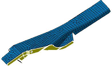
251 Page 251
252 Splitting Quads Page 252 This task demonstrates how to split quadrangle mesh elements into triangle mesh elements. Open the sample05.catanalysis document from the samples directory. Before You Begin: You have to enter the Surface Meshing product For this, double-click Smart Surface Mesh.1 feature from the specification tree (below Nodes and Elements feature) and then click YES (Continue anyway?) in the Warning box. You have to mesh the surface. For this, click the Mesh the Part icon from the Execution toolbar. You will then click OK in the Mesh the Part dialog box. 1. Click the Split Quads icon from the Mesh Operators toolbar. 2. Select the geometry to be meshed by clicking on the part. The Split Quads dialog box appears.


253 Page 253 Shortest diagonal: Choosing between both diagonals the shortest. Best quality: Considering all the active quality criteria and choosing the diagonal with the best quality elements. The quadrangle mesh elements are split into triangle mesh elements. 3. Click OK in the Split Quads dialog box.

254 Page 254 Workbench Description This section presents a description of the toolbars and specification tree of the Advanced Meshing Methods workbench. You can click the sensitive areas on these images to see related documentation. Advanced Meshing Tools Toolbars Surface Meshing Workshop Toolbars


255 Page 255 Meshing Methods Toolbar Global Specifications Toolbar Local Specifications Toolbar Execution Toolbar Edition Tools Toolbar Exit Toolbar Import/Export Toolbar Welding Meshing Methods Toolbar Mesh Analysis Tools Toolbar Mesh Transformations Toolbar Mesh Operators Toolbar CATAnalysis
256 Page 256 Meshing Methods Toolbar See Meshing using Beams Surface Meshing Methods See Meshing using OCTREE Triangles See Meshing the Surface Part Solid Meshing Methods See OCTREE Tetrahedron Mesher See Tetrahedron Filler
257 Page 257 Global Specifications Toolbar See Setting Global Meshing Parameters
258 Page 258 Local Specifications Toolbar See Removing Holes See Removing Cracks See Removing Faces See Adding/Removing Constraints (Specifications) See Imposing Nodes (Specifications) See Specify a domain
259 Page 259 Execution Toolbar See Simplifying the Geometry See Removing the Geometrical Simplification See Meshing the Part See Removing the Mesh
260 Page 260 Edition Tools Toolbar See Cleaning Holes See Adding/Removing Constraints (Modifications) See Imposing Nodes (Modifications) See Removing the Mesh Domain Edition See Re-meshing a Domain See Removing the Mesh by Domain See Locking a Domain Modify Mesh See Mesh Editing See Splitting Quadrangles
261 Page 261 Exit Toolbar See Leaving the Surface Meshing Workshop
262 Page 262 Import/Export Toolbar See Exporting the Mesh See Importing the Mesh
263 Page 263 Welding Meshing Methods Toolbar See Meshing Spot Welds See Meshing Seam Welding Connections
264 Page 264 Mesh Analysis Tools Toolbar (in the Surface Meshing workshop) See Displaying Free Edges See Checking Intersections / Interferences See Analyzing Element Quality See Switching to Standard/Quality Visualization Mode See Cutting Plane See Displaying Element Orientation See Returning Mesh Part Statistics (only available in the Surface Meshing workshop)
265 Page 265 Mesh Transformations Toolbar See Translation See Rotation See Symmetry See Extrusion by Translation See Extrusion by Rotation See Extrusion by Symmetry
266 Page 266 Mesh Operators Toolbar See Offsetting the Mesh See Splitting Quads
267 Page 267 CATAnalysis A CATAnalysis file is composed of: 1. Links Manager, which references the part or the product to be analyzed. 2. Connection Design Manager, which contains the analysis design connections. 3. Finite Element Model, which contains the specifications of finite element model. Analysis Manager Links Manager The Links Manager gives you the directory path and the main information on the linked documents or files. Product Part Results and Computations: gives you the directory path of the CATAnalysisComputations and the CATAnalysisResults files. Connection Design Manager The Connection Design Manager is composed of: General Design Connection Point Design Connection Point Design Connection within one Part Line Design Connection Line Design Connection within one Part
268 Page 268 Finite Element Model The Finite Element Model is composed of: Nodes and Elements Properties Modulation Group Analysis Case
269 Customizing Page 269 This section describes the different type of setting customization you can perform in the Analysis workbenches using the Tools -> Options... submenu. This type of customization is stored in permanent setting files: these settings will not be lost if you end your session. 1. Select the Tools -> Options... submenu. The Options dialog box appears. 2. Select the Analysis & Simulation category. The following tab appears: These tabs lets you define the: general settings graphic settings post processing settings quality settings storage settings 3. Change the desired parameters. 4. Click OK in the Options dialog box when done.

270 Page 270 General This task explains how to customize Analysis & Simulation general settings. The General tab deals with the following settings: the default analysis case choice the specification tree display Click here to see the parent page. Default Analysis Case Define a default starting analysis case This option lets you define a default analysis case that will be inserted each time you enter the Generative Structural Analysis workbench or the Advanced Meshing Tools workbench. Before defining a default analysis case using Tools->Options command, make sure you started the Analysis & Simulation (Generative Structural Analysis or Advanced Meshing Tools) workbench at least once. The default starting analysis case is Static Analysis. You can decide that the new default case will be: Static Analysis Frequency Analysis Free Frequency Analysis
271 Page 271 The cases will only be displayed if an analysis workbench has been loaded at least once because the listed cases are linked to the Analysis workbenches last loaded. By default, this option is deactivated. Specification Tree Show parameters This option lets you display parameters in the specification tree. By default, this option is deactivated. Show relations This option lets you display relations in the specification tree. By default, this option is deactivated.
272 Page 272 Graphics This page deals with the following options: Nodes Elements Click here to see the parent page. Nodes This option lets you select the symbol and color you wish to assign to the nodes. Elements This option lets you define the shrink of 1D elements.

273 Page 273 Quality This page deals with the following options: Quality Criteria Default Standard File Export Default Format Click here to see the parent page. Quality Criteria This frame lets you visualize the quality criteria that are taken into account and their limit values between: good and poor elements poor and bad elements By default, all the Quality Criteria are taken into account. The limit values change as you define the Default Standard File option.
FEM Surface. Preface Getting Started Basic Tasks Glossary Index TOC. Dassault Systèmes All rights reserved.
 TOC FEM Surface Preface Getting Started Basic Tasks Glossary Index Dassault Systèmes 1994-99. All rights reserved. file:////moyenne/users/cma/fmsdoccxr5/fmsenglish/fmsug.doc/src/fmsugtoc.htm [09/26/2000
DMU Engineering Analysis Review
 Page 1 DMU Engineering Analysis Review Preface Using This Guide Where to Find More Information Conventions What's New? Getting Started Inserting a CATAnalysis Document Using DMU Space Analysis From CATAnalysis
DMU Engineering Analysis Review
 DMU Engineering Analysis Review Overview Conventions What's New? Getting Started Entering DMU Engineering Analysis Review Workbench Generating an Image Visualizing Extrema Generating a Basic Analysis Report
Electrical 3D Design & Documentation
 Electrical 3D Design & Documentation Page 1 Overview Conventions User Tasks Using Electrical 3D Design & Documentation Entering the Electrical Assembly Design Workbench Entering the Electrical Part Design
Equipment Support Structures
 Page 1 Equipment Support Structures Preface Using This Guide Where to Find More Information Conventions What's New? Getting Started Setting Up Your Session Creating a Simple Structural Frame Creating Non-uniform
Equipment Support Structures
 Equipment Support Structures Overview Conventions What's New? Getting Started Setting Up Your Session Creating a Simple Structural Frame Creating Non-uniform Columns Creating Plates with Openings Bracing
Fastening Review Overview Basic Tasks DMU Fastening Review Interoperability Workbench Description Customizing Index
 Fastening Review Overview Conventions Basic Tasks Displaying Joined Parts in a Balloon Running the Fastening Rules Analysis Reporting Creating Structural Reports Creating Flat Reports DMU Fastening Review
Electrical Harness Installation
 Electrical Harness Installation Page 1 Overview Conventions What's New? Getting Started Entering the Workbench Setting Up the Options Creating a Bundle Segment Document Creating Construction Points Defining
NC Manufacturing Verification
 NC Manufacturing Verification Page 1 Preface Using This Guide Where to Find More Information Conventions What's New? User Tasks Accessing NC Manufacturing Verification Comparing the Machined Stock Part
NC Manufacturing Verification
 NC Manufacturing Verification Overview Conventions What's New? User Tasks Accessing NC Manufacturing Verification Comparing the Machined Stock Part and the Design Part Pick Point Analysis in Video Mode
Electrical Harness Flattening
 Electrical Harness Flattening Overview Conventions What's New? Getting Started Accessing the Electrical Harness Flattening Workbench Defining the Harness Flattening Parameters Extracting Data Flattening
Tolerance Analysis of Deformable Assembly
 Tolerance Analysis of Deformable Assembly Overview Conventions What's New? Getting Started Entering the Workbench Creating a New Analysis Importing the Assembly Definition Computing a Tolerance Analysis
Structure Preliminary Layout
 Page 1 Structure Preliminary Layout Preface Using This Guide Where to Find More Information What's New? Getting Started Setting Up Your Session Defining the Hull Form Setting Up Your Grid Creating Molded
Electrical Library Version 5 Release 13. Electrical Library
 Electrical Library Page 1 Overview Conventions What's New? Getting Started Entering the Electrical Part Design Workbench Defining a Single Insert Connector Defining a Cavity Connection Point Entering Electrical
Circuit Board Design Version 5 Release 13. Circuit Board Design
 Circuit Board Design Page 1 Overview Conventions What's New? Getting Started Accessing the Circuit Board Workbench Creating a Board Pocket and Holes Constraint Area Exporting Data Importing Data User Tasks
FreeStyle Shaper Optimizer & Profiler
 FreeStyle Shaper Optimizer & Profiler Page 1 Preface Using This Guide More Information What's New? Getting Started Starting the FreeStyle Workbench Creating a First Surface Editing the Surface Creating
Electrical System Functional Definition
 Electrical System Functional Definition Preface What's New? Getting Started Basic Tasks Advanced Tasks Workbench Description Customizing Glossary Index Dassault Systèmes 1994-2000. All rights reserved.
Getting Started. These tasks should take about 20 minutes to complete. Getting Started
 Getting Started Getting Started This tutorial will guide you step-by-step through your first ELFINI and Generative Part Structural Analysis session, allowing you to get acquainted with the product. You
DMU Space Analysis Version 5 Release 13. DMU Space Analysis
 Page 1 DMU Space Analysis Preface Using This Guide More Information Conventions What's New? Getting Started Setting Up Your Session Measuring Minimum Distances Sectioning Detecting Clashes Measuring Between
Electrical Wire Routing
 Electrical Wire Routing Page 1 Overview Conventions What's New? Getting Started Accessing the Workbench Creating the Bundle Selecting Systems with External Data Routing Wires from External Data User Tasks
Structure Preliminary Layout
 Structure Preliminary Layout Overview Conventions What's New? Getting Started Setting Up Your Session Defining the Hull Form Setting Up Your Grid Creating Molded Forms Creating a Compartment Creating Boundaries
DMU Space Engineering Assistant User Guide
 Page 1 DMU Space Engineering Assistant User Guide Overview Conventions What's New? Getting Started User Tasks Setting Up Your Session Running a Interference Workbench Description DMU Space Engineering
Electrical System Functional Definition
 Electrical System Functional Definition Overview Conventions What's New? Getting Started Creating a New System Creating Equipment Creating Connectors Creating a Signal Connecting Saving Your System User
DMU Space Engineering Assistant User Guide
 DMU Space Engineering Assistant User Guide Overview Conventions What's New? Getting Started User Tasks Setting Up Your Session Running an Interference Analysis Workbench Description DMU Space Engineering
FreeStyle Shaper & Optimizer
 FreeStyle Shaper & Optimizer Preface What's New Getting Started Basic Tasks Advanced Tasks Workbench Description Customizing Glossary Index Dassault Systèmes 1994-99. All rights reserved. Preface CATIA
Prismatic Machining Overview What's New Getting Started User Tasks
 Prismatic Machining Overview Conventions What's New Getting Started Enter the Workbench Create a Pocketing Operation Replay the Toolpath Create a Profile Contouring Operation Create a Drilling Operation
DMU Optimizer Overview What's New? Getting Started User Tasks
 DMU Optimizer Overview Conventions What's New? Getting Started Starting a Session Generating a Silhouette Generating a Wrapping Generating a Thickness Generating an Offset Generating a Free Space User
DMU Fitting Simulator
 Page 1 DMU Fitting Simulator Preface Using This Guide More Information Conventions What's New? Getting Started Using Tracks Starting a Session Recording a Track Using Automatic Path Finder Using the Smooth
Aerospace Sheetmetal Design
 Aerospace Sheetmetal Design Page 1 Overview Conventions What's New? Getting Started Entering the Aerospace SheetMetal Design Workbench Defining the Aerospace SheetMetal Parameters Creating a Web from a
ABAQUS for CATIA V5 Tutorials
 ABAQUS for CATIA V5 Tutorials AFC V2.5 Nader G. Zamani University of Windsor Shuvra Das University of Detroit Mercy SDC PUBLICATIONS Schroff Development Corporation www.schroff.com ABAQUS for CATIA V5,
Shape Sculptor Version 5 Release 13. Shape Sculptor
 Shape Sculptor Page 1 Overview Using This Guide Where to Find More Information What's New? Getting Started Entering the Workbench Importing a Polygonal Mesh Decimating a Polygonal Mesh User Tasks Input
CATIA Surface Design
 CATIA V5 Training Exercises CATIA Surface Design Version 5 Release 19 September 2008 EDU_CAT_EN_GS1_FX_V5R19 Table of Contents (1/2) Creating Wireframe Geometry: Recap Exercises 4 Creating Wireframe Geometry:
Product Structure Version 5 Release 13. Product Structure
 Product Structure Page 1 Site Map Preface Conventions What's New? Basic Tasks Entering the Product Structure Workbench Opening a CATProduct with a Progress Bar Selecting Products only Selecting Modes Inserting
Generative Part Structural Analysis Fundamentals
 CATIA V5 Training Foils Generative Part Structural Analysis Fundamentals Version 5 Release 19 September 2008 EDU_CAT_EN_GPF_FI_V5R19 About this course Objectives of the course Upon completion of this course
Tekla Structures Analysis Guide. Product version 21.0 March Tekla Corporation
 Tekla Structures Analysis Guide Product version 21.0 March 2015 2015 Tekla Corporation Contents 1 Getting started with analysis... 7 1.1 What is an analysis model... 7 Analysis model objects...9 1.2 About
CATIA V5 Analysis. CATIA V5 Training Foils. CATIA V5 Analysis. Copyright DASSAULT SYSTEMES 1. Student Notes:
 CATIA V5 Training Foils CATIA V5 Analysis Version 5 Release 19 January 2009 EDU_CAT_EN_V5A_FF_V5R19 1 Lesson 1: Introduction to Finite Element Analysis About this Course Introduction CATIA is a robust
Knowledge Expert Overview What's New? Getting Started Basic Tasks Advanced Tasks Reference
 Knowledge Expert Overview Conventions What's New? Getting Started Creating an Expert Check Creating an Expert Rule Basic Tasks About RuleBases Storing a Rule Base in a Catalog Using a Rule Base Stored
Knowledge Advisor Overview What's New? Getting Started User Tasks
 Knowledge Advisor Overview Conventions What's New? Getting Started Using Parameters Using Formulas Using Rules Using Checks User Tasks Working with Parameters Creating a Parameter Introducing Parameters
Lesson 3: Surface Creation
 Lesson 3: Surface Creation In this lesson, you will learn how to create surfaces from wireframes. Lesson Contents: Case Study: Surface Creation Design Intent Stages in the Process Choice of Surface Sweeping
Introduction to ANSYS FLUENT Meshing
 Workshop 04 CAD Import and Meshing from Conformal Faceting Input 14.5 Release Introduction to ANSYS FLUENT Meshing 2011 ANSYS, Inc. December 21, 2012 1 I Introduction Workshop Description: CAD files will
Lesson 6: Assembly Structural Analysis
 Lesson 6: Assembly Structural Analysis In this lesson you will learn different approaches to analyze the assembly using assembly analysis connection properties between assembly components. In addition
Piping Design. Site Map Preface Getting Started Basic Tasks Advanced Tasks Customizing Workbench Description Index
 Piping Design Site Map Preface Getting Started Basic Tasks Advanced Tasks Customizing Workbench Description Index Dassault Systèmes 1994-2001. All rights reserved. Site Map Piping Design member member
Introduction to MSC.Patran
 Exercise 1 Introduction to MSC.Patran Objectives: Create geometry for a Beam. Add Loads and Boundary Conditions. Review analysis results. MSC.Patran 301 Exercise Workbook - Release 9.0 1-1 1-2 MSC.Patran
Workshop 1: Basic Skills
 Workshop 1: Basic Skills 14.5 Release Introduction to ANSYS Fluent Meshing 2011 ANSYS, Inc. December 21, 2012 1 I Introduction Workshop Description: This workshop shows some of the clean up tools in Tgrid
Module 4A: Creating the 3D Model of Right and Oblique Pyramids
 Inventor (5) Module 4A: 4A- 1 Module 4A: Creating the 3D Model of Right and Oblique Pyramids In Module 4A, we will learn how to create 3D solid models of right-axis and oblique-axis pyramid (regular or
Human Posture Analysis
 Human Posture Analysis Page 1 Preface Using This Guide Where to Find More Information Conventions What's New? Getting Started Creating a Manikin User Tasks Using the Posture Editor Segments Degree of Freedom
Product Engineering Optimizer
 CATIA V5 Training Foils Product Engineering Optimizer Version 5 Release 19 January 2009 EDU_CAT_EN_PEO_FI_V5R19 1 About this course Objectives of the course Upon completion of this course, you will learn
Piping & Instrumentation Diagrams
 Piping & Instrumentation Diagrams Preface Using This Guide What's New? Getting Started Entering the Workbench Setting up Working Units and Grid Placing Components Routing a Piping Line or I & C Loop Placing
v Stratigraphy Modeling TIN Surfaces GMS 10.3 Tutorial Introduction to the TIN (Triangulated Irregular Network) surface object
 surface object") v. 10.3 GMS 10.3 Tutorial Stratigraphy Modeling TIN Surfaces Introduction to the TIN (Triangulated Irregular Network) surface object Objectives Learn to create, read, alter, and manage TIN data from within
v. 10.3 GMS 10.3 Tutorial Stratigraphy Modeling TIN Surfaces Introduction to the TIN (Triangulated Irregular Network) surface object Objectives Learn to create, read, alter, and manage TIN data from within
HVAC Diagrams Preface What's New? Getting Started User Tasks
 HVAC Diagrams Preface Using This Guide What's New? Getting Started Entering the Workbench Setting up Working Units and Grid Placing Components Routing an HVAC Line Placing Components in a Line Repositioning
Chapter 6. Concept Modeling. ANSYS, Inc. Proprietary Inventory # May 11, ANSYS, Inc. All rights reserved.
 Chapter 6 Concept Modeling 6-1 Contents Concept Modeling Creating Line Bodies Modifying i Line Bodies Cross Sections Cross Section Alignment Cross Section Offset Surfaces From Lines Surfaces From Sketches
SheetMetal Design Version 5 Release 13. SheetMetal Design
 SheetMetal Design Page 1 Overview Conventions What's New? Getting Started Entering the Workbench Defining the Parameters Creating the First Wall Creating the Side Walls Creating a Cutout Creating Automatic
Inventor 201. Work Planes, Features & Constraints: Advanced part features and constraints
 Work Planes, Features & Constraints: 1. Select the Work Plane feature tool, move the cursor to the rim of the base so that inside and outside edges are highlighted and click once on the bottom rim of the
STL Rapid Prototyping
 STL Rapid Prototyping Page 1 Preface Using this Guide More Information Conventions What's New Getting Started Basic Surface Tessellation Repairing the Mesh Checking the Mesh Quality User Tasks Starting
3. MODELING A THREE-PIPE INTERSECTION (3-D)
") 3. MODELING A THREE-PIPE INTERSECTION (3-D) This tutorial employs primitives that is, predefined GAMBIT modeling components and procedures. There are two types of GAMBIT primitives: Geometry Mesh Geometry
3. MODELING A THREE-PIPE INTERSECTION (3-D) This tutorial employs primitives that is, predefined GAMBIT modeling components and procedures. There are two types of GAMBIT primitives: Geometry Mesh Geometry
STL Rapid Prototyping
 CATIA V5 Training Foils STL Rapid Prototyping Version 5 Release 19 January 2009 EDU_CAT_EN_STL_FI_V5R19 1 About this course Objectives of the course Upon completion of this course you will learn how to
GMS 8.2 Tutorial Stratigraphy Modeling TIN Surfaces Introduction to the TIN (triangulated irregular network) surface object
 surface object") v. 8.2 GMS 8.2 Tutorial Introduction to the TIN (triangulated irregular network) surface object Objectives Learn to create, read, alter and manage TIN data from within GMS. Prerequisite Tutorials None
v. 8.2 GMS 8.2 Tutorial Introduction to the TIN (triangulated irregular network) surface object Objectives Learn to create, read, alter and manage TIN data from within GMS. Prerequisite Tutorials None
Tutorial THE BASICS GEOMETRY CLEANUP AND SHELL MESHING
 Tutorial THE BASICS GEOMETRY CLEANUP AND SHELL MESHING Table of Contents 1. Introduction... 2 1.2. Prerequisites... 2 1.3. Problem description... 2 1.4. Data files... 2 2. Read the CAD file... 3 3. Checking
Building the Finite Element Model of a Space Satellite
 Exercise 4 Building the Finite Element Model of a Space Satellite 30000 20000 Objectives: mesh & MPC s on a Space Satellite. Perform Model and Element Verification. Learn how to control mesh parameters
Selective Space Structures Manual
 Selective Space Structures Manual February 2017 CONTENTS 1 Contents 1 Overview and Concept 4 1.1 General Concept........................... 4 1.2 Modules................................ 6 2 The 3S Generator
Introduction to ANSYS Fluent Meshing
 Workshop 06: Mesh Creation Including Removal of Gaps and Baffle Thickness 14.5 Release Introduction to ANSYS Fluent Meshing 1 2011 ANSYS, Inc. December 21, 2012 I Introduction Workshop Description: Fluent
Product Engineering Optimizer
 Product Engineering Optimizer Overview Conventions What's New? Getting Started Basic Tasks Using the Optimize Function Defining an Optimization Getting Familiar with the Optimization Dialog Box The Problem
GMS 10.0 Tutorial Stratigraphy Modeling TIN Surfaces Introduction to the TIN (Triangulated Irregular Network) surface object
 surface object") v. 10.0 GMS 10.0 Tutorial Stratigraphy Modeling TIN Surfaces Introduction to the TIN (Triangulated Irregular Network) surface object Objectives Learn to create, read, alter, and manage TIN data from within
v. 10.0 GMS 10.0 Tutorial Stratigraphy Modeling TIN Surfaces Introduction to the TIN (Triangulated Irregular Network) surface object Objectives Learn to create, read, alter, and manage TIN data from within
Surface Modeling With TINs
 GMS TUTORIALS The TIN module in GMS is used for general-purpose surface modeling. TIN is an acronym for Triangulated Irregular Network. TINs are formed by connecting a set of xyz points with edges to form
CATIA V5 FEA Tutorials Release 14
 CATIA V5 FEA Tutorials Release 14 Nader G. Zamani University of Windsor SDC PUBLICATIONS Schroff Development Corporation www.schroff.com www.schroff-europe.com CATIA V5 FEA Tutorials 2-1 Chapter 2 Analysis
15. SAILBOAT GEOMETRY
 SAILBOAT GEOMETRY 15. SAILBOAT GEOMETRY In this tutorial you will import a STEP file that describes the geometry of a sailboat hull. You will split the hull along the symmetry plane, create a flow volume
Repairing a Boundary Mesh
 Tutorial 1. Repairing a Boundary Mesh Introduction TGrid offers several tools for mesh repair. While there is no right or wrong way to repair a mesh, the goal is to improve the quality of the mesh with
1 - Introduction Training Guide Objectives WorkXplore Environment Importing and Opening CAD Files 5
 Table Of Contents 1.1 - Training Guide Objectives Table Of Contents 1 - Introduction 3 1.1 - Training Guide Objectives... 3 1.2 - WorkXplore Environment... 3 2 - Importing and Opening CAD Files 5 2.1 -
Parametric Modeling Design and Modeling 2011 Project Lead The Way, Inc.
 Parametric Modeling Design and Modeling 2011 Project Lead The Way, Inc. 3D Modeling Steps - Sketch Step 1 Sketch Geometry Sketch Geometry Line Sketch Tool 3D Modeling Steps - Constrain Step 1 Sketch Geometry
Section 8.3: Examining and Repairing the Input Geometry. Section 8.5: Examining the Cartesian Grid for Leakages
 Chapter 8. Wrapping Boundaries TGrid allows you to create a good quality boundary mesh using a bad quality surface mesh as input. This can be done using the wrapper utility in TGrid. The following sections
EXTERNAL AERODYNAMICS
 Tutorial EXTERNAL AERODYNAMICS HYBRID VOLUME MESH Table of Contents 1. Introduction... 2 1.1. Prerequisites... 2 1.2. Case description... 2 1.3. Data files... 2 2. Read the ANSA database... 3 3. Create
SDC. Engineering Analysis with COSMOSWorks. Paul M. Kurowski Ph.D., P.Eng. SolidWorks 2003 / COSMOSWorks 2003
 Engineering Analysis with COSMOSWorks SolidWorks 2003 / COSMOSWorks 2003 Paul M. Kurowski Ph.D., P.Eng. SDC PUBLICATIONS Design Generator, Inc. Schroff Development Corporation www.schroff.com www.schroff-europe.com
Introduction to ANSYS FLUENT Meshing
 Workshop 02 Volume Fill Methods Introduction to ANSYS FLUENT Meshing 1 2011 ANSYS, Inc. December 21, 2012 I Introduction Workshop Description: Mesh files will be read into the Fluent Meshing software ready
Exercise 1: Axle Structural Static Analysis
 Exercise 1: Axle Structural Static Analysis The purpose of this exercise is to cover the basic functionality of the Mechanical Toolbar (MTB) in the context of performing an actual analysis. Details of
SURFACE WATER MODELING SYSTEM. 2. Change to the Data Files Folder and open the file poway1.xyz.
 SURFACE WATER MODELING SYSTEM Mesh Editing This tutorial lesson teaches manual finite element mesh generation techniques that can be performed using SMS. It gives a brief introduction to tools in SMS that
Elfini Solver Verification
 Page 1 Elfini Solver Verification Preface Using this Guide Where to Find More Information Conventions What's new User Tasks Static Analysis Cylindrical Roof Under its Own Weight Morley's Problem Twisted
Tutorial 2: Particles convected with the flow along a curved pipe.
 Tutorial 2: Particles convected with the flow along a curved pipe. Part 1: Creating an elbow In part 1 of this tutorial, you will create a model of a 90 elbow featuring a long horizontal inlet and a short
User Guide. for. JewelCAD Professional Version 2.0
 User Guide Page 1 of 121 User Guide for JewelCAD Professional Version 2.0-1 - User Guide Page 2 of 121 Table of Content 1. Introduction... 7 1.1. Purpose of this document... 7 2. Launch JewelCAD Professional
Free Convection Cookbook for StarCCM+
 ME 448/548 February 28, 2012 Free Convection Cookbook for StarCCM+ Gerald Recktenwald gerry@me.pdx.edu 1 Overview Figure 1 depicts a two-dimensional fluid domain bounded by a cylinder of diameter D. Inside
Mechanical Design V5R19 Update
 CATIA V5 Training Foils Mechanical Design V5R19 Update Version 5 Release 19 August 2008 EDU_CAT_EN_MD2_UF_V5R19 1 About this course Objectives of the course Upon completion of this course you will be able
Solidworks 2006 Surface-modeling
 Solidworks 2006 Surface-modeling (Tutorial 2-Mouse) Surface-modeling Solid-modeling A- 1 Assembly Design Design with a Master Model Surface-modeling Tutorial 2A Import 2D outline drawing into Solidworks2006
Introduction to ANSYS DesignModeler
 Lecture 5 Modeling 14. 5 Release Introduction to ANSYS DesignModeler 2012 ANSYS, Inc. November 20, 2012 1 Release 14.5 Preprocessing Workflow Geometry Creation OR Geometry Import Geometry Operations Meshing
Compartment and Access
 Compartment and Access Preface Using This Guide What's New? Getting Started Entering the Workbench Set Correct Working Units and Grid Saving Documents User Tasks Creating/Modifying Wall Systems Building
Piping & Instrumentation Diagrams
 Page 1 Piping & Instrumentation Diagrams Preface Using This Guide What's New? Getting Started Entering the Workbench Setting up Working Units and Grid Placing Components Routing a Piping Line or I & C
Training Guide TopSolid Fea
 Training Guide i 2012, Missler Software. 7, Rue du Bois Sauvage F-91055 Evry, FRANCE Web: http://www.topsolid.com E-mail: info@topsolid.com All rights reserved. This information is subject to change without
SimLab Release Notes. 1 A l t a i r E n g i n e e r i n g
 SimLab 11.0 Release Notes 1 A l t a i r E n g i n e e r i n g System Support extended to load and save GDA/SLB files of size greater than 4GB. Memory allocation is enhanced to support large models. Kubrix
2: Static analysis of a plate
 2: Static analysis of a plate Topics covered Project description Using SolidWorks Simulation interface Linear static analysis with solid elements Finding reaction forces Controlling discretization errors
FEA BENDING, TORSION, TENSION, and SHEAR TUTORIAL in CATIA
 1 FEA BENDING, TORSION, TENSION, and SHEAR TUTORIAL in CATIA This tutorial shows the basics of a solid bending, torsional, tension, and shear FEA (Finite Elemental Analysis) model in CATIA. Torsion - page
Introduction to ANSYS ICEM CFD
 Lecture 1 Introduction to ANSYS ICEM CFD 14.5 Release Introduction to ANSYS ICEM CFD 2012 ANSYS, Inc. April 1, 2013 1 Release 14.5 Purpose/Goals Ansys ICEM CFD is a general purpose grid generating program
Multi-Pockets Machining
 CATIA V5 Training Foils Multi-Pockets Machining Version 5 Release 19 January 2009 EDU_CAT_EN_MPG_FF_V5R19 1 About this course Objectives of the course Upon completion of this course you will be able to
Electrical Cableway Routing
 Electrical Cableway Routing Preface Using This Guide What's New? Getting Started Entering the Workbench Placing a Hanger Routing a Loft Through Hangers Placing a Conduit on a Run Saving Documents Updating
Compartment and Access
 Compartment and Access Page 1 Preface Using This Guide What's New? Getting Started Entering the Workbench Set Correct Working Units and Grid Saving Documents User Tasks Creating/Modifying Wall Systems
User s Manual ❹ Tools
 User s Manual ❹ Tools 2 CONTENTS I. THE NEW UPGRADED INTERFACE of SCADA Pro 5 II. DETAILED DESCRIPTION OF THE NEW INTERFACE 6 1. Tools 6 1.1 Structural Elements 6 1.2 USC-WCS 12 1.3 Model 13 1.4 Members
Manipulating the Boundary Mesh
 Chapter 7. Manipulating the Boundary Mesh The first step in producing an unstructured grid is to define the shape of the domain boundaries. Using a preprocessor (GAMBIT or a third-party CAD package) you
Version 2 (for Rhinoceros 4) Getting Started
 Getting Started") Version 2 (for Rhinoceros 4) Getting Started 25. June 2008 rhinoreverse is a plug-in application for use within the Rhinoceros CAD-system (www.rhino3d.com). It has been designed to enable the user to create
Version 2 (for Rhinoceros 4) Getting Started 25. June 2008 rhinoreverse is a plug-in application for use within the Rhinoceros CAD-system (www.rhino3d.com). It has been designed to enable the user to create
CATIA V5 Parametric Surface Modeling
 CATIA V5 Parametric Surface Modeling Version 5 Release 16 A- 1 Toolbars in A B A. Wireframe: Create 3D curves / lines/ points/ plane B. Surfaces: Create surfaces C. Operations: Join surfaces, Split & Trim
Human Posture Analysis
 Human Posture Analysis Overview Conventions What's New? Getting Started Creating a Manikin User Tasks Using the Posture Editor Selecting or Editing the DOF (Degree of Freedom) Displaying and Editing Angular
Chapter 2 Parametric Modeling Fundamentals
 2-1 Chapter 2 Parametric Modeling Fundamentals Create Simple Extruded Solid Models Understand the Basic Parametric Modeling Procedure Create 2-D Sketches Understand the "Shape before Size" Approach Use
Introduction to ANSYS
 Lecture 1 Introduction to ANSYS ICEM CFD 14. 0 Release Introduction to ANSYS ICEM CFD 1 2011 ANSYS, Inc. March 22, 2015 Purpose/Goals Ansys ICEM CFD is a general purpose grid generating program Grids for
v Mesh Editing SMS 11.2 Tutorial Requirements Mesh Module Time minutes Prerequisites None Objectives
 v. 11.2 SMS 11.2 Tutorial Objectives This tutorial lesson teaches manual mesh generation and editing techniques that can be performed using SMS. It should be noted that manual methods are NOT recommended.