Cam makes a higher kinematic pair with follower. Cam mechanisms are widely used because with them, different types of motion can be possible.
|
|
|
- Tamsyn Grace Bond
- 6 years ago
- Views:
Transcription
1 CAM MECHANISMS
2 Cam makes a higher kinematic pair with follower. Cam mechanisms are widely used because with them, different types of motion can be possible. Cams can provide unusual and irregular motions that may be impossible with the other types of mechanisms. However, the manufacturing of cams is expensive and the wear effect due to the contact stresses is a disadvantage. On the other hand, cams are not proper for the systems with high speeds and heavy loads.
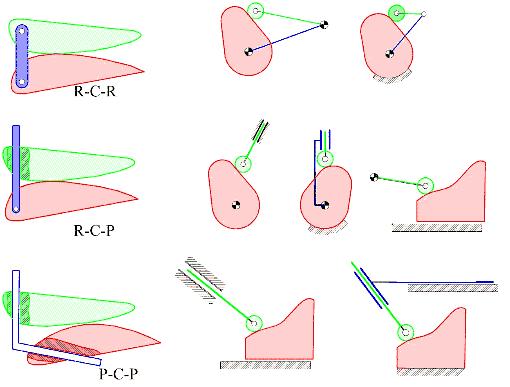
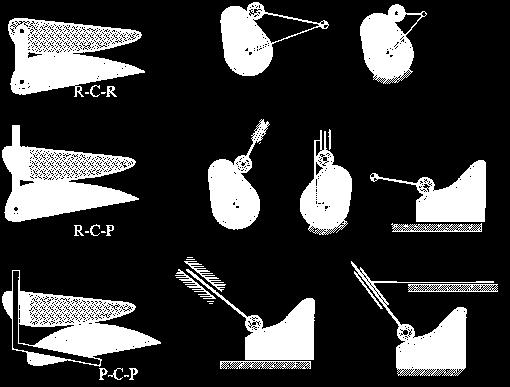
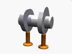
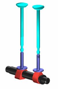
3 Classification of Cams According to kinematic structure:

4 According to shape of the cam: Spherical, Helical, Conical, 3 dimensional


5 According to the type of contact: Force closed Form closed
6 Classification of Followers According to the construction of the surface in contact(roller, flat faced, cylindrical, spherical) According to the type of movement (translating or oscillating) The translating follower is also classified as radial or off-set according to the location of movement with respect to the cam rotation axis.

7
8 Drawing Cam Profile for a Given Motion Curve of the Follower -Follower is roller-type -Follower makes off-set translation -Follower radius is given - Base circle radius is given
, since t = / s= a 1 / +a 0 Let H= Total follower")
9 BASIC CAM MOTION CURVES In this section some well known motion curves will be explained for the rise portion of the motion curve only. 1. Linear Motion : Equation describing a linear motion with respect to time is: s= a 1 t +a 0 Assuming constant angular velocity for the input cam ( ), since t = / s= a 1 / +a 0 Let H= Total follower rise (Stroke) = angular rotation of the cam corresponding to the total rise of the follower. a=0 The motion curve and velocity and acceleration curves are as shown. Note that the acceleration is zero for the entire motion (a=0) but is infinite at the ends. Due to infinite accelerations, high inertia forces will be created at the start and at the end even at moderate speeds. The cam profile will be discontinuous. One basic rule in cam design is that this motion curve must be continuous and the first and second derivatives (corresponding to the velocity and acceleration of the follower) must be finite even at the transition points.


10 2. Simple Harmonic Motion Simple harmonic motion curve is widely used since it is simple to design. The curve is the projection of a circle about the cam rotation axis as shown in the figure. The equations relating the follower displacement velocity and acceleration to the cam rotation angle are:

11 2. Simple Harmonic Motion(cont d) v max V max = a max = Note that even though the velocity and acceleration is finite, the maximum acceleration is discontinuous at the start and end of the rise period. Hence the third derivative, jerk, will be infinite at the start and end of the rise portion. This curve will not be suitable for high or moderate speeds.

12 3. Parabolic or Constant Acceleration Motion Curve For the range 0 < < /2 For the range /2 < <

13 3. Parabolic or Constant Acceleration Motion Curve (cont d) In this case the velocity and accelerations will be finite. There is a constant acceleration for the first half and a constant deceleration in the second half of the cycle. However the third derivative, jerk, will be infinite at the two ends as in the case of simple harmonic motion. Displacement, velocity and acceleration curves are as shown. This motion curve has the lowest possible acceleration.

14 4. Cycloidal Motion Curve If a circle rolls along a straight line without slipping, a point on the circumference traces a curve that is called a cycloid. This curve can be drawn by drawing a circle with center C on the line OO. The circumference of the circle is equal to the total rise; or the diameter is H/.The circumference is divided into a number of equal parts corresponding to the divisions along the horizontal axis. The points around the circle are first projected to the vertical centerline of the circle and then parallel to OO to the corresponding vertical line on the diagram.

15 4. Cycloidal Motion Curve (cont d) The equations relating the follower displacement, velocity and acceleration to the cam rotation angle are: Within the curves we have thus far seen, cycloidal motion curve has the best dynamic characteristics. The acceleration is finite at all times and the starting and ending acceleration is zero. It will yield a cam mechanism with the lowest vibration, stress, noise and shock characteristics. Hence for high speed applications this motion curve is recommended.
16 Normalization of the motion curves In order to compare the motion curves that were discussed we take, =1 rad/s H= 1 unit = 1 radian This procedure is known as normalization. Using this procedure one can then easily compare all these curves with respect to each other. This comparison is shown in the Figure. Cv, Ca and Cj, are the maximum velocity, acceleration and jerk values for the normalized curves. One can determine the maximum velocity, acceleration and jerk for any H, and as:
) (from Table) multiply this equation by H and substitute / instead of, s=h/2(1-cos( / )) (the real eq n) Vmax=( /2) H / =1,57 H / =Cv H / a max = =C a H 2 /")
17 Also the equations given for the normalized motion curves can be converted for any rise H, angular velocity and crank rotation by multiplying the equation by H and substituting / instead of. For simple harmonic motion: s=1/2(1-cos( )) (from Table) multiply this equation by H and substitute / instead of, s=h/2(1-cos( / )) (the real eq n) Vmax=( /2) H / =1,57 H / =Cv H / a max = =C a H 2 / 2 =4,93 H 2 / 2
18 Cam Size Determination Cam size determination is related to the determination of the base circle. In almost all applications it is required to minimize the size of the cam. Large cams are not desired due to the following reasons: 1. More space is required. 2. Unbalanced mass increases 3. Follower has a longer path for each cycle. Therefore, angular velocity of the follower and the surface velocity increases. However as we decrease the cam size, the following factors arise: 1. The force transmission characteristics deteriorate. The cam profile becomes more steep. 2. The curvature of the cam profile decreases (sharp curves) 3. Strength requirements due to the forces and moments acting on the cam. In practice the cam size is determined by considering two factors: a) The pressure angle b) The minimum radius of curvature

19 Pressure Angle The pressure angle, which is the reciprocal of the transmission angle (i.e. = /2- ) is defined as: In cams there is point contact and the force is transmitted along the common normal of the two contacting curves. Cams with roller followers have pressure angles whereas with flat faced followers don t have.

20 Pressure Angle (cont d) The pressure angle is a function of cam rotation angle. The force ratio for the pressure angle may be expressed by using the kinematics of the mechanism. For an inline translating roller follower radial cam v B3 = v B2 + v B3/B2 v B3 = Follower velocity = ds/dt= v B2 = Velocity of point B on the cam= r (r=ob= s+r b +r r. r b is the base circle radius, r r is the roller radius) The relative velocity direction is along the path tangent.
21 Pressure Angle (cont d) This value can easily be determined from the motion curve. r r may be determined from strength considerations The designer selects an acceptable maximum pressure angle and finds the base circle radius. Maximum pressure angle usually depends on the speed, load and place of application of the cam mechanism. In general, If the cam speed is less then 30 rpm: max 45 0 If the cam speed is greater then 30 rpm: max 60 0
22 Cam Curvature In practice for roller followers it is common to determine the cam size using the maximum pressure angle criteria and then check that the cam curvature is satisfactory. In case of flat faced followers, the cam curvature is the determining criteria for the cam size. Graphically when laying out the cam profile, first the successive positions of the follower according to the cam motion curve is drawn while keeping the cam fixed.

23 Cam Curvature (cont d) For example, for a cam with the selected roller radius and base circle radius, the positions of the roller are A,B,C,D and E. However, it is not possible to draw a smooth curve that is tangent to all the roller circles. With Profile#1, the cam profile is tangent to the circles at positions A,C and E, and in Profile#2 the cam profile is tangent to positions A,B and E. There is no cam profile that will be tangent to all the positions of the roller. This is known as undercutting and occurs whenever the radius of curvature of the cam profile is less than the radius of the roller ( p <r r ). In order to eliminate this condition a larger base circle radius is selected or, if strength conditions permit, the radius of the roller is reduced.
24 Cam Curvature (cont d) For roller followers the following recommendations may be made to avoid undercutting: Use smaller roller diameter (this is limited by the contact stress at the surface) Utilize a larger cam size (this is usually not desired. It must be applied if necessary) Employ an internal cam (the curvature is less critical but they are more expensive to manufacture)

25 Cam Curvature (cont d) A similar case is shown in case of flat faced followers. The cam profile is not tangent to all the successive positions of the follower.
Homework No. 6 (40 points). Due on Blackboard before 8:00 am on Friday, October 13th.
. Due on Blackboard before 8:00 am on Friday, October 13th.") ME 35 - Machine Design I Fall Semester 017 Name of Student: Lab Section Number: Homework No. 6 (40 points). Due on Blackboard before 8:00 am on Friday, October 13th. The important notes for this homework
ME 35 - Machine Design I Fall Semester 017 Name of Student: Lab Section Number: Homework No. 6 (40 points). Due on Blackboard before 8:00 am on Friday, October 13th. The important notes for this homework
Kinematics of Machines Prof. A. K. Mallik Department of Mechanical Engineering Indian Institute of Technology, Kanpur. Module 10 Lecture 1
 Kinematics of Machines Prof. A. K. Mallik Department of Mechanical Engineering Indian Institute of Technology, Kanpur Module 10 Lecture 1 So far, in this course we have discussed planar linkages, which
ON THE VELOCITY OF A WEIGHTED CYLINDER DOWN AN INCLINED PLANE
 ON THE VELOCITY OF A WEIGHTED CYLINDER DOWN AN INCLINED PLANE Raghav Grover and Aneesh Agarwal RG (Grade 12 High School), AA (Grade 11 High School) Department of Physics, The Doon School, Dehradun. raghav.503.2019@doonschool.com,
An Evaluation of Profiles for Disk Cams with In-line Roller Followers
 An Evaluation of Profiles for Disk Cams with In-line Roller Followers M.R.M.Rejab 1, M.M.Rahman 1, Z.Hamedon 2, M.S.M.Sani 1, M.M.Noor 1 and K.Kadirgama 1 1 Faculty of Mechanical Engineering, Universiti
MACHINES AND MECHANISMS
 MACHINES AND MECHANISMS APPLIED KINEMATIC ANALYSIS Fourth Edition David H. Myszka University of Dayton PEARSON ж rentice Hall Pearson Education International Boston Columbus Indianapolis New York San Francisco
Kinematics of Machines Prof. A. K. Mallik Department of Mechanical Engineering Indian Institute of Technology, Kanpur. Module - 3 Lecture - 1
 Kinematics of Machines Prof. A. K. Mallik Department of Mechanical Engineering Indian Institute of Technology, Kanpur Module - 3 Lecture - 1 In an earlier lecture, we have already mentioned that there
Mechanisms. Updated: 18Apr16 v7
 Mechanisms Updated: 8Apr6 v7 Mechanism Converts input motion or force into a desired output with four combinations of input and output motion Rotational to Oscillating Rotational to Rotational Rotational
SAMPLE STUDY MATERIAL. Mechanical Engineering. Postal Correspondence Course. Theory of Machines. GATE, IES & PSUs
 TOM - ME GATE, IES, PSU 1 SAMPLE STUDY MATERIAL Mechanical Engineering ME Postal Correspondence Course Theory of Machines GATE, IES & PSUs TOM - ME GATE, IES, PSU 2 C O N T E N T TOPIC 1. MACHANISMS AND
Kinematics of Machines. Brown Hills College of Engineering & Technology
 Introduction: mechanism and machines, kinematic links, kinematic pairs, kinematic chains, plane and space mechanism, kinematic inversion, equivalent linkages, four link planar mechanisms, mobility and
Unit WorkBook 4 Level 5 ENG U36 Advanced Mechanical Principles 2018 UniCourse Ltd. All rights Reserved. Sample
 018 UniCourse Ltd. All rights Reserved. Pearson BTEC Levels 5 Higher Nationals in Engineering (RQF) Unit 36: Advanced Mechanical Principles Unit Workbook 4 in a series of 4 for this unit Learning Outcome
Manipulator Path Control : Path Planning, Dynamic Trajectory and Control Analysis
 Manipulator Path Control : Path Planning, Dynamic Trajectory and Control Analysis Motion planning for industrial manipulators is a challenging task when obstacles are present in the workspace so that collision-free
5/27/12. Objectives. Plane Curves and Parametric Equations. Sketch the graph of a curve given by a set of parametric equations.
 Objectives Sketch the graph of a curve given by a set of parametric equations. Eliminate the parameter in a set of parametric equations. Find a set of parametric equations to represent a curve. Understand
Manipulator Dynamics: Two Degrees-of-freedom
 Manipulator Dynamics: Two Degrees-of-freedom 2018 Max Donath Manipulator Dynamics Objective: Calculate the torques necessary to overcome dynamic effects Consider 2 dimensional example Based on Lagrangian
WEEKS 1-2 MECHANISMS
 References WEEKS 1-2 MECHANISMS (METU, Department of Mechanical Engineering) Text Book: Mechanisms Web Page: http://www.me.metu.edu.tr/people/eres/me301/in dex.ht Analitik Çözümlü Örneklerle Mekanizma
MECHANICAL ENGINEERING
 MECHANICAL ENGINEERING ESE TOPICWISE OBJECTIVE SOLVED PAPER-II FROM (1995-2018) UPSC Engineering Services Examination State Engineering Service Examination & Public Sector Examination. IES MASTER PUBLICATION
Design and Analysis of Globoidal Cam Index Drive
 Volume 2 ssue pp 16-16 June21 www.ijsret.org SSN 22 2 Design and Analysis of Globoidal Cam ndex Drive Suresh Sanap 1, Ketan Jagtap 2 and Keshav Nandurkar 1-2 Government Polytechnic, Nashik E Mail: sanapsd@gmail.com
Trajectory Planning for Automatic Machines and Robots
 Luigi Biagiotti Claudio Melchiorri Trajectory Planning for Automatic Machines and Robots Springer 1 Trajectory Planning 1 1.1 A General Overview on Trajectory Planning 1 1.2 One-dimensional Trajectories
PROBLEMS AND EXERCISES PROBLEMS
 64 Fundamentals of Kinematics and Dynamics of Machines and Mechanisms PROBLEMS AND EXERCISES PROBLEMS 1. In Figure 1.14c an inverted slider-crank mechanism is shown. b. If the input is the displacement
[1] involuteσ(spur and Helical Gear Design)
![[1] involuteσ(spur and Helical Gear Design)](/thumbs/82/86018000.jpg "[1] involuteσ(spur and Helical Gear Design)") [1] involuteσ(spur and Helical Gear Design) 1.3 Software Content 1.3.1 Icon Button There are 12 icon buttons: [Dimension], [Tooth Form], [Accuracy], [Strength], [Sliding Graph], [Hertz Stress Graph], [FEM],
[1] involuteσ(spur and Helical Gear Design) 1.3 Software Content 1.3.1 Icon Button There are 12 icon buttons: [Dimension], [Tooth Form], [Accuracy], [Strength], [Sliding Graph], [Hertz Stress Graph], [FEM],
Introduction to Solid Modeling Using SolidWorks 2008 COSMOSMotion Tutorial Page 1
 Introduction to Solid Modeling Using SolidWorks 2008 COSMOSMotion Tutorial Page 1 In this tutorial, we will learn the basics of performing motion analysis using COSMOSMotion. Although the tutorial can
3. The three points (2, 4, 1), (1, 2, 2) and (5, 2, 2) determine a plane. Which of the following points is in that plane?
, (1, 2, 2) and (5, 2, 2) determine a plane. Which of the following points is in that plane?") Math 4 Practice Problems for Midterm. A unit vector that is perpendicular to both V =, 3, and W = 4,, is (a) V W (b) V W (c) 5 6 V W (d) 3 6 V W (e) 7 6 V W. In three dimensions, the graph of the equation
Math 4 Practice Problems for Midterm. A unit vector that is perpendicular to both V =, 3, and W = 4,, is (a) V W (b) V W (c) 5 6 V W (d) 3 6 V W (e) 7 6 V W. In three dimensions, the graph of the equation
Appendix E. Plane Geometry
 Appendix E Plane Geometry A. Circle A circle is defined as a closed plane curve every point of which is equidistant from a fixed point within the curve. Figure E-1. Circle components. 1. Pi In mathematics,
Design of Cam Profile using Higher Order B-Spline
 Design of Cam Profile using Higher Order B-Spline Laxmi Kant Sahu 1, Om Prakash Gupta 2, Meena Sahu 3 1 Department of Mechanical Engineering, Govt. Polytechnic College, Korba, Chhattisgarh-495450, India;
Position and Displacement Analysis
 Position and Displacement Analysis Introduction: In this chapter we introduce the tools to identifying the position of the different points and links in a given mechanism. Recall that for linkages with
REPRESENTATION OF LAWS OF MOVEMENT FOR THE CAM- FOLLOWER MECHANISM
 REPRESENTATION OF LAWS OF MOVEMENT FOR THE CAM- FOLLOWER MECHANISM Bogdan-George Frîncu, Raluca-Andreea Mosoia, Nicolae Alexandru Stoica, Alina-Maria Petrescu University POLITEHNICA of Bucharest, Bucharest,
Influence of geometric imperfections on tapered roller bearings life and performance
 Influence of geometric imperfections on tapered roller bearings life and performance Rodríguez R a, Calvo S a, Nadal I b and Santo Domingo S c a Computational Simulation Centre, Instituto Tecnológico de
9.1 Parametric Curves
 Math 172 Chapter 9A notes Page 1 of 20 9.1 Parametric Curves So far we have discussed equations in the form. Sometimes and are given as functions of a parameter. Example. Projectile Motion Sketch and axes,
CHAPTER 1 : KINEMATICS
 KINEMATICS : It relates to the study of the relative motion between the parts of a machine. Let us consider a reciprocating engine, in this the piston is made to reciprocate in the cylinderdue to the applied
Kinematics: Intro. Kinematics is study of motion
 Kinematics is study of motion Kinematics: Intro Concerned with mechanisms and how they transfer and transform motion Mechanisms can be machines, skeletons, etc. Important for CG since need to animate complex
The diagram above shows a sketch of the curve C with parametric equations
 1. The diagram above shows a sketch of the curve C with parametric equations x = 5t 4, y = t(9 t ) The curve C cuts the x-axis at the points A and B. (a) Find the x-coordinate at the point A and the x-coordinate
Solutions to Chapter 6 Exercise Problems A 1 O 4 B 2
 Solutions to Chapter 6 Exercise Problems Problem 6.1: Design a double rocker, four-bar linkage so that the base link is 2-in and the output rocker is 1-in long. The input link turns counterclockwise 60
Logarithmic Profiles of Rollers in Roller Bearings and Optimization of the Profiles
 NTN TECHNICAL REVIEW No7 007 The 006 Japan Society of Mechanical Engineers Young Engineers Award Logarithmic Profiles of Rollers in Roller Bearings and Optimization of the Profiles Hiroki FUJIWARA Tatsuo
Simulation Driven Optimized Mechanism Drive
 Simulation Driven Optimized Mechanism Drive August 30, 2011 Elias Taye, PhD Wm Wrigley Jr. Company Subsidiary of Mars Inc. 1 AGENDA Introduction of Wm Wrigley Jr. Company Original Design of the Mechanical
Mechanism Design. Four-bar coupler-point curves
 Mechanism Design Four-bar coupler-point curves Four-bar coupler-point curves A coupler is the most interesting link in any linkage. It is in complex motion, and thus points on the coupler can have path
Kinematics, Dynamics, and Design of Machinery, 3 nd Ed.
 MATLAB KINEMATIC PROGRAMS To Supplement the Textbook Kinematics, Dynamics, and Design of Machinery, 3 nd Ed. By K. J. Waldron, G. L. Kinzel, and S. Agrawal 2016 by G. Kinzel Department of Mechanical and
MATHEMATICS FOR ENGINEERING TRIGONOMETRY
 MATHEMATICS FOR ENGINEERING TRIGONOMETRY TUTORIAL SOME MORE RULES OF TRIGONOMETRY This is the one of a series of basic tutorials in mathematics aimed at beginners or anyone wanting to refresh themselves
September 20, Chapter 5. Simple Mechanisms. Mohammad Suliman Abuhaiba, Ph.D., PE
 Chapter 5 Simple Mechanisms 1 Mohammad Suliman Abuhaiba, Ph.D., PE 2 Assignment #1 All questions at the end of chapter 1 st Exam: Saturday 29/9/2018 3 Kinematic Link or Element kinematic link (link) or
Human Motion. Session Speaker Dr. M. D. Deshpande. AML2506 Biomechanics and Flow Simulation PEMP-AML2506
 AML2506 Biomechanics and Flow Simulation Day 02A Kinematic Concepts for Analyzing Human Motion Session Speaker Dr. M. D. Deshpande 1 Session Objectives At the end of this session the delegate would have
Application Note #3412
 Application Note #3412 Smoothing Velocity Profiling (using IT and VT commands) Background: Moving a motor from one position to another involves accelerating the motor to a certain velocity, traveling at
COMPARISON OF TWO FINITE ELEMENT MODELS OF BRISTLES OF GUTTER BRUSHES FOR STREET SWEEPING
 Proceedings of the 4 th International Conference on Fracture Fatigue and Wear, pp. 22-226, 25 COMPARISON OF TWO FINITE ELEMENT MODELS OF BRISTLES OF GUTTER BRUSHES FOR STREET SWEEPING M.M. Abdel-Wahab,
Mathematical Model and Surface Deviation of Cylindrical Gears With Curvilinear Shaped Teeth Cut by a Hob Cutter
 Jui-Tang Tseng Graduate Student Chung-Biau Tsay Professor Department of Mechanical Engineering, National Chiao Tung University, Hsinchu, Taiwan 3000, Republic of China Mathematical Model Surface Deviation
Manipulator trajectory planning
 Manipulator trajectory planning Václav Hlaváč Czech Technical University in Prague Faculty of Electrical Engineering Department of Cybernetics Czech Republic http://cmp.felk.cvut.cz/~hlavac Courtesy to
Chapter 1 Introduction
 Chapter 1 Introduction Generally all considerations in the force analysis of mechanisms, whether static or dynamic, the links are assumed to be rigid. The complexity of the mathematical analysis of mechanisms
GEOMETRY AND GRAPHICS EXAMPLES AND EXERCISES. Preface
 GEOMETRY AND GRAPHICS EXAMPLES AND EXERCISES Preface This textbook is intended for students of subjects Constructive Geometry and Computer Graphics at the Faculty of Mechanical Engineering at Czech Technical
Evaluating the knot vector to synthesize the cam motion using NURBS
 Evaluating the knot vector to synthesize the cam motion using NURBS T.T.N. Nguyen 1, S. Kurtenbach 2, M. Hüsing 3 and B. Corves 4 Department of Mechanism Theory and Dynamics of Machines, RWTH Aachen University,
Structural Configurations of Manipulators
 Structural Configurations of Manipulators 1 In this homework, I have given information about the basic structural configurations of the manipulators with the concerned illustrations. 1) The Manipulator
Chapter 4. Mechanism Design and Analysis
 Chapter 4. Mechanism Design and Analysis All mechanical devices containing moving parts are composed of some type of mechanism. A mechanism is a group of links interacting with each other through joints
East Penn School District Secondary Curriculum
 East Penn School District Secondary Curriculum A Planned Course Statement for Analytic Geometry and Calculus (BC) AP Course # 360 Grade(s) 12 Department: Math ength of Period (mins.) 41 Total Clock Hours:
Goals: - to be able to recognize the position-time, velocity-time and acceleration-time graphs of each of these main types of motion:
 Unit: One-Dimensional Kinematics Level: 1 Prerequisites: None Points to: Goals: - to be able to recognize the position-time, velocity-time and acceleration-time graphs of each of these main types of motion:
Theory of Machines Course # 1
 Theory of Machines Course # 1 Ayman Nada Assistant Professor Jazan University, KSA. arobust@tedata.net.eg March 29, 2010 ii Sucess is not coming in a day 1 2 Chapter 1 INTRODUCTION 1.1 Introduction Mechanisms
6.1 Introduction. 캠 - 종동절계 (cam-follower system) 캠 : 직접접촉에의해특정운동을일으켜종동절을구동하는데사용하는기계요소
 캠 : 직접접촉에의해특정운동을일으켜종동절을구동하는데사용하는기계요소") 기구메커니즘 Kinematics of Machinery 181013 Ch6. Cam design 6.1 Introduction 캠 - 종동절계 (cam-follower system) 캠 : 직접접촉에의해특정운동을일으켜종동절을구동하는데사용하는기계요소 Cam + Follower Cam의운동 (rotation) Follower의운동 (oscillation, translation)
기구메커니즘 Kinematics of Machinery 181013 Ch6. Cam design 6.1 Introduction 캠 - 종동절계 (cam-follower system) 캠 : 직접접촉에의해특정운동을일으켜종동절을구동하는데사용하는기계요소 Cam + Follower Cam의운동 (rotation) Follower의운동 (oscillation, translation)
Encoder applications. I Most common use case: Combination with motors
 3.5 Rotation / Motion - Encoder applications 64-424 Intelligent Robotics Encoder applications I Most common use case: Combination with motors I Used to measure relative rotation angle, rotational direction
PARAMETRIC EQUATIONS AND POLAR COORDINATES
 9 ARAMETRIC EQUATIONS AND OLAR COORDINATES So far we have described plane curves b giving as a function of f or as a function of t or b giving a relation between and that defines implicitl as a function
Chapter 1. Linear Equations and Straight Lines. 2 of 71. Copyright 2014, 2010, 2007 Pearson Education, Inc.
 Chapter 1 Linear Equations and Straight Lines 2 of 71 Outline 1.1 Coordinate Systems and Graphs 1.4 The Slope of a Straight Line 1.3 The Intersection Point of a Pair of Lines 1.2 Linear Inequalities 1.5
Lecture 3. Planar Kinematics
 Matthew T. Mason Mechanics of Manipulation Outline Where are we? s 1. Foundations and general concepts. 2.. 3. Spherical and spatial kinematics. Readings etc. The text: By now you should have read Chapter
1 Trigonometry. Copyright Cengage Learning. All rights reserved.
 1 Trigonometry Copyright Cengage Learning. All rights reserved. 1.1 Radian and Degree Measure Copyright Cengage Learning. All rights reserved. Objectives Describe angles. Use radian measure. Use degree
(1) (2) be the position vector for a generic point. If this point belongs to body 2 (with helical motion) its velocity can be expressed as follows:
 (2) be the position vector for a generic point. If this point belongs to body 2 (with helical motion) its velocity can be expressed as follows:") The 14th IFToMM World Congress, Taipei, Taiwan, October 25-30, 2015 DOI Number: 10.6567/IFToMM.14TH.WC.OS6.025 A Rolling-Joint Higher-Kinematic Pair for Rotary-Helical Motion Transformation J. Meneses
The 14th IFToMM World Congress, Taipei, Taiwan, October 25-30, 2015 DOI Number: 10.6567/IFToMM.14TH.WC.OS6.025 A Rolling-Joint Higher-Kinematic Pair for Rotary-Helical Motion Transformation J. Meneses
Optics II. Reflection and Mirrors
 Optics II Reflection and Mirrors Geometric Optics Using a Ray Approximation Light travels in a straight-line path in a homogeneous medium until it encounters a boundary between two different media The
Computer Life (CPL) ISSN: Finite Element Analysis of Bearing Box on SolidWorks
 ISSN: Finite Element Analysis of Bearing Box on SolidWorks") Computer Life (CPL) ISSN: 1819-4818 Delivering Quality Science to the World Finite Element Analysis of Bearing Box on SolidWorks Chenling Zheng 1, a, Hang Li 1, b and Jianyong Li 1, c 1 Shandong University
Computer Life (CPL) ISSN: 1819-4818 Delivering Quality Science to the World Finite Element Analysis of Bearing Box on SolidWorks Chenling Zheng 1, a, Hang Li 1, b and Jianyong Li 1, c 1 Shandong University
Development of a Mechanical Creative Combination Based on 3D Printing
 Development of a Mechanical Creative Combination Based on 3D Printing Xinwen Li, Yingjie Tang * College of Nuclear Technology and Automation Engineering, Chengdu University of Technology, Chengdu 610059,
Modelling of mechanical system CREATING OF KINEMATIC CHAINS
 Modelling of mechanical system CREATING OF KINEMATIC CHAINS Mechanism Definitions 1. a system or structure of moving parts that performs some function 2. is each system reciprocally joined moveable bodies
CE2302 STRUCTURAL ANALYSIS I Important Questions PART B
 CE2302 STRUCTURAL ANALYSIS I Important Questions PART B UNIT I 1. Determine the vertical and horizontal displacement of the joint B in a pin jointed frame shown in fig. 2. The cross sectional area of each
Transportation Engineering - II Dr.Rajat Rastogi Department of Civil Engineering Indian Institute of Technology - Roorkee
 Transportation Engineering - II Dr.Rajat Rastogi Department of Civil Engineering Indian Institute of Technology - Roorkee Lecture 18 Vertical Curves and Gradients Dear students, I welcome you back to the
Analytical and Applied Kinematics
 Analytical and Applied Kinematics Vito Moreno moreno@engr.uconn.edu 860-614-2365 (cell) http://www.engr.uconn.edu/~moreno Office EB1, hours Thursdays 10:00 to 5:00 1 This course introduces a unified and
Section 10.1 Polar Coordinates
 Section 10.1 Polar Coordinates Up until now, we have always graphed using the rectangular coordinate system (also called the Cartesian coordinate system). In this section we will learn about another system,
Properties of a Circle Diagram Source:
 Properties of a Circle Diagram Source: http://www.ricksmath.com/circles.html Definitions: Circumference (c): The perimeter of a circle is called its circumference Diameter (d): Any straight line drawn
About Graphing Lines
 About Graphing Lines TABLE OF CONTENTS About Graphing Lines... 1 What is a LINE SEGMENT?... 1 Ordered Pairs... 1 Cartesian Co-ordinate System... 1 Ordered Pairs... 2 Line Segments... 2 Slope of a Line
Complex Numbers, Polar Equations, and Parametric Equations. Copyright 2017, 2013, 2009 Pearson Education, Inc.
 8 Complex Numbers, Polar Equations, and Parametric Equations Copyright 2017, 2013, 2009 Pearson Education, Inc. 1 8.5 Polar Equations and Graphs Polar Coordinate System Graphs of Polar Equations Conversion
Unit 13: Periodic Functions and Trig
 Date Period Unit 13: Periodic Functions and Trig Day Topic 0 Special Right Triangles and Periodic Function 1 Special Right Triangles Standard Position Coterminal Angles 2 Unit Circle Cosine & Sine (x,
CHAPTER 3 MATHEMATICAL MODEL
 38 CHAPTER 3 MATHEMATICAL MODEL 3.1 KINEMATIC MODEL 3.1.1 Introduction The kinematic model of a mobile robot, represented by a set of equations, allows estimation of the robot s evolution on its trajectory,
Simulation Model for Coupler Curve Generation using Five Bar Planar Mechanism With Rotation Constraint
 Simulation Model for Coupler Curve Generation using Five Bar Planar Mechanism With Rotation Constraint A. K. Abhyankar, S.Y.Gajjal Department of Mechanical Engineering, NBN Sinhgad School of Engineering,
Path of contact calculation KISSsoft
 Path of contact calculation KISSsoft 04-2010 KISSsoft AG - +41 55 254 20 50 Uetzikon 4 - +41 55 254 20 51 8634 Hombrechtikon - info@kisssoft.ag Switzerland - www.kisssoft.ag Path of contact calculation
Mechanism Synthesis. Introduction: Design of a slider-crank mechanism
 Mechanism Synthesis Introduction: Mechanism synthesis is the procedure by which upon identification of the desired motion a specific mechanism (synthesis type), and appropriate dimensions of the linkages
CHAPTER 4 INCREASING SPUR GEAR TOOTH STRENGTH BY PROFILE MODIFICATION
 68 CHAPTER 4 INCREASING SPUR GEAR TOOTH STRENGTH BY PROFILE MODIFICATION 4.1 INTRODUCTION There is a demand for the gears with higher load carrying capacity and increased fatigue life. Researchers in the
Strömningslära Fluid Dynamics. Computer laboratories using COMSOL v4.4
 UMEÅ UNIVERSITY Department of Physics Claude Dion Olexii Iukhymenko May 15, 2015 Strömningslära Fluid Dynamics (5FY144) Computer laboratories using COMSOL v4.4!! Report requirements Computer labs must
Answers. (1) Parallelogram. Remember: A four-sided flat shape where the opposite sides are parallel is called a parallelogram. Here, AB DC and BC AD.
 Parallelogram. Remember: A four-sided flat shape where the opposite sides are parallel is called a parallelogram. Here, AB DC and BC AD.") Answers (1) Parallelogram Remember: A four-sided flat shape where the opposite sides are parallel is called a parallelogram. Here, AB DC and BC AD. (2) straight angle The angle whose measure is 180 will
Answers (1) Parallelogram Remember: A four-sided flat shape where the opposite sides are parallel is called a parallelogram. Here, AB DC and BC AD. (2) straight angle The angle whose measure is 180 will
For each question, indicate whether the statement is true or false by circling T or F, respectively.
 True/False For each question, indicate whether the statement is true or false by circling T or F, respectively. 1. (T/F) Rasterization occurs before vertex transformation in the graphics pipeline. 2. (T/F)
Time: 3 hour Total Marks: 90
 Time: 3 hour Total Marks: 90 General Instructions: 1. All questions are compulsory. 2. The question paper consists of 34 questions divided into four sections A, B, C, and D. 3. Section A contains of 8
PARAMETRIC EQUATIONS AND POLAR COORDINATES
 10 PARAMETRIC EQUATIONS AND POLAR COORDINATES PARAMETRIC EQUATIONS & POLAR COORDINATES A coordinate system represents a point in the plane by an ordered pair of numbers called coordinates. PARAMETRIC EQUATIONS
Trajectory planning in Cartesian space
 Robotics 1 Trajectory planning in Cartesian space Prof. Alessandro De Luca Robotics 1 1 Trajectories in Cartesian space! in general, the trajectory planning methods proposed in the joint space can be applied
Reflection and Refraction
 Reflection and Refraction Theory: Whenever a wave traveling in some medium encounters an interface or boundary with another medium either (or both) of the processes of (1) reflection and (2) refraction
The Law of Reflection
 If the surface off which the light is reflected is smooth, then the light undergoes specular reflection (parallel rays will all be reflected in the same directions). If, on the other hand, the surface
Section 4.2 Radians, Arc Length, and Area of a Sector
 1330 - Section 4.2 Radians, Arc Length, and Area of a Sector Two rays that have a common endpoint (vertex) form an angle. One ray is the initial side and the other is the terminal side. We typically will
2.3 Circular Functions of Real Numbers
 www.ck12.org Chapter 2. Graphing Trigonometric Functions 2.3 Circular Functions of Real Numbers Learning Objectives Graph the six trigonometric ratios as functions on the Cartesian plane. Identify the
Geometry. Cluster: Experiment with transformations in the plane. G.CO.1 G.CO.2. Common Core Institute
 Geometry Cluster: Experiment with transformations in the plane. G.CO.1: Know precise definitions of angle, circle, perpendicular line, parallel line, and line segment, based on the undefined notions of
change divided by original times 100 divide by the bottom, times by the top Divide both the top and bottom of a fraction by the same number
 Averages and Range How do you work out the mean? How do you get the mode? How do you work out the median? How do you work out the range? How do you work out the mean for a frequency table? Add up all the
NUMERICAL ANALYSIS OF ROLLER BEARING
 Applied Computer Science, vol. 12, no. 1, pp. 5 16 Submitted: 2016-02-09 Revised: 2016-03-03 Accepted: 2016-03-11 tapered roller bearing, dynamic simulation, axial load force Róbert KOHÁR *, Frantisek
Glossary of dictionary terms in the AP geometry units
 Glossary of dictionary terms in the AP geometry units affine linear equation: an equation in which both sides are sums of terms that are either a number times y or a number times x or just a number [SlL2-D5]
Robots are built to accomplish complex and difficult tasks that require highly non-linear motions.
 Path and Trajectory specification Robots are built to accomplish complex and difficult tasks that require highly non-linear motions. Specifying the desired motion to achieve a specified goal is often a
Math 2 Coordinate Geometry Part 3 Inequalities & Quadratics
 Math 2 Coordinate Geometry Part 3 Inequalities & Quadratics 1 DISTANCE BETWEEN TWO POINTS - REVIEW To find the distance between two points, use the Pythagorean theorem. The difference between x 1 and x
slope rise run Definition of Slope
 The Slope of a Line Mathematicians have developed a useful measure of the steepness of a line, called the slope of the line. Slope compares the vertical change (the rise) to the horizontal change (the
FEMLAB Exercise 1 for ChE366
 FEMLAB Exercise 1 for ChE366 Problem statement Consider a spherical particle of radius r s moving with constant velocity U in an infinitely long cylinder of radius R that contains a Newtonian fluid. Let
Design Elements Horizontal Milos N. Mladenovic Assistant Professor Department of Built Environment
 Design Elements Horizontal Milos N. Mladenovic Assistant Professor Department of Built Environment 01.03.2017 Outline Highway alignment Vehicle cornering forces Minimum radius Circular curve elements Transition
MathsGeeks
 1. Find the first 3 terms, in ascending powers of x, of the binomial expansion of and simplify each term. (4) 1. Bring the 3 out as the binomial must start with a 1 Using ( ) ( ) 2. (a) Show that the equation
Scientific Journal of Silesian University of Technology. Series Transport Zeszyty Naukowe Politechniki Śląskiej. Seria Transport
 Scientific Journal of Silesian University of Technology. Series Transport Zeszyty Naukowe Politechniki Śląskiej. Seria Transport Volume 96 07 p-issn: 009-334 e-issn: 450-549 DOI: https://doi.org/0.0858/sjsutst.07.96.8
Example Examination 2IV
 Example Examination IV60-04071 (translated version IV10 4 july 01, 14:00-17:00) This examination consist of four questions with in total 16 subquestion. Each subquestion weighs equally. In all cases: EXPLAIN
Lab # 3 - Angular Kinematics
 Purpose: Lab # 3 - Angular Kinematics The objective of this lab is to understand the relationship between segment angles and joint angles. Upon completion of this lab you will: Understand and know how
Chapter 5. An Introduction to Trigonometric Functions 1-1
 Chapter 5 An Introduction to Trigonometric Functions Copyright (c) The McGraw-Hill Companies, Inc. Permission required for reproduction or display. 1-1 5.1 A half line or all points extended from a single
DYNAMIC ANALYSIS OF A GENERATOR ON AN ELASTIC FOUNDATION
 DYNAMIC ANALYSIS OF A GENERATOR ON AN ELASTIC FOUNDATION 7 DYNAMIC ANALYSIS OF A GENERATOR ON AN ELASTIC FOUNDATION In this tutorial the influence of a vibrating source on its surrounding soil is studied.
Precalculus Lesson 6.1: Angles and Their Measure Mrs. Snow, Instructor
 Precalculus Lesson 6.1: Angles and Their Measure Mrs. Snow, Instructor In Trigonometry we will be working with angles from 0 to 180 to 360 to 720 and even more! We will also work with degrees that are