First Animated Model Yellow Submarine
|
|
|
- Barbra Bryan
- 6 years ago
- Views:
Transcription
1 Course: 3D Design Title: First Animated Model Yellow Submarine Blender: Version 2.6X Level: Beginning Author; Neal Hirsig (May 2012) First Animated Model Yellow Submarine Most of you are perhaps too young to remember the Beatles song Yellow Submarine. In this tutorial we will create a simple animated model of a yellow submarine. Open Blender. If a default cube object exists, right-click to select it and then press the XKEY and delete the cube. Background Image: We will use a background image taken from the Beatles Yellow Submarine album cover. This image file called Yellowsub.jpg can be downloaded on the class website.

2 Before we can add a background image file to the Background Image tool we must first add the image to the UV editor Click on the Editor Type button in the lower left corner of the 3D Editor Viewport Header and select UV Image Editor. This will open Blender s UV Image Editor. Click on the Image Button in the UV Editor Header and select Open.


3 This will open Blenders file Browser. Locate the Yellowsub.jpg file, select it and press on the Open button. This will place the Yellowsub.jpg image into the UV Editor.


4 Now we will add the image to the Background Images Panel. Click on the Editor Type button in the lower left corner of the UV Image Editor Header and select 3D View.

5 To incorporate this image into our Blender scene open up the right properties panel of the 3D Editor by clicking on the plus (+) in the upper right corner of the 3D view port or press the NKEY Scroll down to the Background Images Panel and click on the Add Image button. Click on the Browse ID Data button located to the left of the open button.


6 Select the Yellowsub.jpg image file from the list.
. This, will active the tool.")
7 This will add the Yellowsub.jpg image file to the background image tool and it will be listed in the Background Images panel. Note that at this point the Background Images panel is a bit grayed out. This is because we have not yet activated the Background Image tool. Place a checkmark into the checkbox to the left of the Background Image panel name (by clicking on it). This, will active the tool.
 NOTE: BACKGROND IMAGES ONLY DISPLAY WHEN IN ORTHOGRAPHIC PROJECTION MODE.")
8 This will display the Background Image panel on your display. To see the background image go to front orthographic view (NUMPAD-1) NOTE: BACKGROND IMAGES ONLY DISPLAY WHEN IN ORTHOGRAPHIC PROJECTION MODE. IF YOU IN PERSPECTIVE MODE, PRESS (NUMPAD-5) TO GO INTO ORTHOGRAPHIC PROJECTION MODE.

9 The background image will not render. It is used only as a guide. We will be using this background image as a modeling guide in Left Side view only. By default the image will be displayed in all orthographic views. Click on the Views dropdown box and select Left side view.
 on the control arrow to the left of the Size control until the Size")
10 We also want the image to be scaled a bit larger than the default scale of 5. Click (repeatedly) on the control arrow to the left of the Size control until the Size scale is set to 7.
.")
11 Notice now that the yellow sub background image will only be displayed in Left Side Orthographic view. Press CTRL-NUMPAD-3. This is the Blender shortcut for Left Side view. The background image should appear on your display (slightly grayed out). (Note: If you are in Left Side Perspective view click NUMPAD-5 to switch to Orthographic view)

12 First, Some Practice: Before we model the submarine we will create a UV sphere objects and look at some of Blender s basic tools. Go to Front View (NUMPAD-1) Left click in the center of the display to set your 3D cursor.

13 Press SHIFT-A. This will display Blender s ADD menu. Select Mesh / UV Sphere. This will place a primitive UV Sphere object in your Blender Scene with its center point at the location of your 3D cursor.
14 Notice the Add UV Sphere controls now available in the left 3D Viewport panel (You may have to drag this window up a bit to see all of the controls)

15 Click on the arrow to the left of the default 32 segments and make it 20 segments. Click on the arrow to the right of the default 16 rings and make it 20 rings.


16 Zoom in a bit by scrolling up your scroll wheel. The new UV Sphere object is currently in Object Mode. Click on the TAB key to place the object in EDIT mode.

17 The TAB key toggles between Object mode and Edit mode. By default all of the vertices, edges and faces of the object are selected. Press the AKEY to deselect all of the spheres sub-objects. The AKEY toggles between selecting everything and de-selecting everything. Press the ZKEY. The sphere is now displayed in wireframe mode.
.")
18 The ZKEY toggles between solid shading mode and wireframe shading mode. Go back to Object mode (TAB). Press the AKEY to deselect the sphere.

19 Select the UV Sphere by right clicking on any of the wireframe lines. Zoom out a bit by scrolling down your scroll wheel.
20 Notice that with the UV Sphere selected, Blender s Transform Widget is displayed at the sphere s center. The Transform widget has a red arrow and a blue arrow. Click and drag the red arrowhead. This allows you to move an object along the object s X-axis. (Try it) Click and drag the blue arrowhead. This allows you to move the object along the object s Z-axis. (Try it) Another way to move (translate) the sphere is to press the GKEY (Grab). This allows you to move the sphere anywhere in the display. Left click to drop the sphere into place. (Try it) Press CTRL-Z. This is Blender s UNDO command. Notice that the UV sphere returns to the last position. Most of Blender s operations can also be canceled in the middle of the operation. Press the GKEY and grab the sphere and move it about. Instead of left-clicking to place it, press the ESC (Escape) Key. This cancels the grab operation.
. This places the object in Rotation mode. Move your cursor in a circular pattern and the object will revolve with it.")
21 Press the SKEY (Scale). Move your cursor toward the object s center to scale it down or away from the object s center to scale it up. Left-click to place the scale. Press the RKEY (Rotation). This places the object in Rotation mode. Move your cursor in a circular pattern and the object will revolve with it. Left-click to place the rotation.
22 Notice at the middle of the right side 3D Editor panel the UV Sphere is named Sphere. Each object in Blender has a unique name.

")
 numerically.")
23 Change the name to Ball by clicking on the name and typing in Ball, then enter Note that the object Ball also appears in the Outliner panel The right side 3D Editor control panel (called the properties panel) also allows for changing the object s Location, Scale or Rotation (Transforms) numerically. Click on the
. Note that the yellow sub background image is displayed in this view.")
24 arrow button to the right or left of the ROTATION-Y entry or click on the number and type in a new one. (Press enter when done typing) Press CTRL-Z to UNDO. Press CTRL-Y to REDO. Press the XKEY and delete the sphere. Go to Left Side View (CTRL-NUMPAD-3). Note that the yellow sub background image is displayed in this view. (Note: If you are in Left Side Perspective view click NUMPAD-5 to switch to Orthographic view)
. Here I have chosen my desktop.")
25 If you are using a MAC computer - Press SHIFT-COMMAND-S to save your Blender file. If you are using a PC computer Press SHIFT-CTRL-S to save your Blender file. This displays Blender s File Browser Editor. Locate the folder you want to save your Blender file (.blend). Here I have chosen my desktop. Type in yellowsubmarine in the filename line and press on the Save as Blender File button.
 or CTRL-S (PC) to save your file.")
 Place your 3D cursor in the center of the yellow")
26 Your Blender file (.blend) is now saved. Note that Blender adds the file extension (.blend) automatically. Once a file is saved once you can use the shortcut COMMAND-S (MAC) or CTRL-S (PC) to save your file. These are many of the basic Blender tools you will need to model the submarine. We can now get down to the real modeling. Modeling: You should now be in Left Side Orthographic View (CTRL-NUMPAD-3) Place your 3D cursor in the center of the yellow sub background (by left-clicking there).


27 Make sure you are in solid shading mode. Click on the shading display dropdown box on the 3D viewport header and make sure it is set to solid. Press SHIFT-A. This will display Blender s ADD menu. Select Mesh / Circle.

28 In the Add Circle panel on the left 3D Editor viewport panel set the number of vertices to 20.


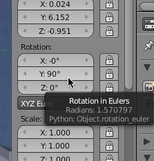
29 In the right 3D Editor Viewport properties panel set the Rotation X to 90 degrees.

30 Zoom in a bit and look at the circle object. At this point it look like a yellow line running vertically on the display. This is because we are looking at the circle from the side and thus it looks like a 2 dimensional line. Press the SKEY (Scale) and scale up the circle object until it is as large (vertically) as the largest part of the sub.
31 Note: You may have to use the green and blue translate (move) arrowheads to position the circle object as shown above - perhaps even SKEY (Scale) it a bit up or down. Press the AKEY to deselect the circle. In Left Side View, it looks like a black line running vertically.
.")
32 Right-click select the circle object again. Press the TAB Button to enter EDIT MODE. (Note: Press the AKEY to select all of the vertices if they are not already selected).
33 We will now EXTRUDE the selected vertices to give the circle mesh some dimension. Press the EKEY (Extrude) then press the YKEY and extrude the circle shape along the Y-axis until it looks like the image below. Left click to set the extrusion in place.

34 Hold you Middle Mouse Button (MMB) down and drag a bit to orbit your view to 3 dimensions.
35 Notice that the background image does not display in a rotated dimensional user view. Press the ZKEY to go to wireframe shading mode.

36 Go to Left Side View (CTRL-NUMPAD-3)
 along the Y-axis.")
37 Notice that when we extrude a set of vertices we are actually creating a new set of vertices and moving them (in this case) along the Y-axis. Press the AKEY to deselect the vertices.

38 Press the BKEY (Box Select) and drag a selection box around the right set of vertices selecting them.
. Press the EKEY (Extrude) and then press the YKEY and extrude the vertices along the Y-axis as shown below. Left click to set the extrusion.")
39 Note: Box selecting a group of vertices as we have done above in wireframe mode selects not only the vertices we can see but also the vertices located directly behind (thus the whole circle of vertices is selected). Press the EKEY (Extrude) and then press the YKEY and extrude the vertices along the Y-axis as shown below. Left click to set the extrusion.

40 Click on the blue translation arrowhead and move the set of vertices down as shown below.

41 Press the SKEY (Scale) and scale the set of vertices down a bit as shown below.

42 Press the ZKEY and go to solid shading mode. Click and drag your middle mouse button to a more dimensional user view.
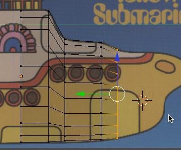
43 Press the ZKEY to go back to wireframe. Go to Left Side View (CTRL-NUMPAD-3) The new set of vertices remain selected, so we can continue without having to reselect. Press the EKEY (Extrude), followed by the YKEY and extrude the vertices a bit more along the Y-axis. Move and/or scale them so that they tend to fit the background image as shown below.

44 Do this again And again.
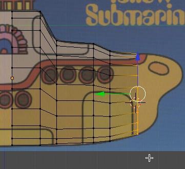
45 And again.
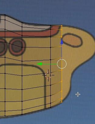
46 And again.
47 And Again.

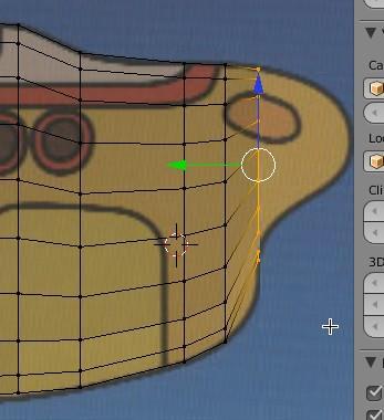
48 Press the AKEY to deselect the vertices. Press the ZKEY to enter shaded mode. MMB drag to orbit your view a bit to 3 dimensions.
 and go back and make sure the full set of vertices are selected before you extrude. Save your file by pressing CRTL-W.")
49 If you are missing some of the faces, it is because you failed to select some of the vertices to extrude. You can CRTL-Z (UNDO) and go back and make sure the full set of vertices are selected before you extrude. Save your file by pressing CRTL-W. Make sure click on the file path and name to confirm saving over an alreadysaved.blend file.

50 Press the ZKEY to return to wireframe mode. Go to Left Side view (CTRL-NUMPAD-3) Press the AKEY to deselect any vertices. Press the BKEY and box select the left side set of vertices. You may want to click your middle mouse button and drag into a 3D view to make sure you have selected the correct vertices. Return to Left Side View (CTRL-NUMPAD-3)

51 Extrude (EKEY) these vertices to the left along the Y axis (YKEY) as shown below. Perform the next 8 extrusions to the left along the Y-axis as shown below.


52 If you have not already done so, press the AKEY to deselect the vertices. Press your Middle mouse button and drag into a more dimensional user view. Press the ZKEY to return to wireframe shading. Go to Left Side View (CTRL- NUMPAD-3
 the middle set of vertices as shown below.")
53 Zoom in on the submarine s rudder area. Box select (BKEY) the middle set of vertices as shown below. (Note that not all of the vertices in the set are selected)

54 Use the transform widget green arrow to move these vertices to the right along the Y-axis as shown below.
55 Press the AKEY to deselect the vertices. Box select (BKEY) the middle set of vertices on the left as shown below. (Note that not all of the vertices in the set are selected)

56 Use the transform widget green arrow to move these vertices to the right along the Y-axis as shown below.
57 Press the AKEY to deselect the vertices. Press the ZKEY to enter solid shading mode. Middle mouse drag to a more dimensional user view.

58 Go back to Left Side View (CTRL-NUMPAD-3). Press the ZKEY to enter wireframe display mode. Zoom in on the nose of the submarine.
 them to the right a bit along the Y Axis")
59 BKEY (Box select) the right set of vertices and EKEY (Extrude) them to the right a bit along the Y Axis (YKEY).

60 With the vertices still selected, Press the Merge button located in the left 3D Editor Tools panel. Then select At Center.


61 This will merge the selected vertices into one vertex.


62 Press the AKEY to deselect the vertices. Press TAB to enter Object Mode. Press the ZKEY to enter solid shading display mode. Rotate your model to a more dimensional user view. Save your file by pressing CRTL-W. Make sure click on the file path and name to confirm saving over an alreadysaved.blend file.
.")
63 Name the object Submarine in the right 3D Editor viewport properties panel. We now need to add a few more elements. Go to Top view (NUMPAD-7). Place your 3D cursor in the center of the sub as shown below.

64 Press SHIFT-A and add a Cylinder object.


65 In the left 3D Editor viewport tool panel, under Add Cylinder, set the number of vertices to 12.

 the submarine object.")
66 Go to Left Side View (CTRL-NUMPAD-3). Press the ZKEY to enter wireframe display mode. Notice that the tube object is located somewhere inside (or below) the submarine object. Use the transform widget blue arrowhead to move the tube object up along the Z-axis.

67 Zoom in a bit. Press the SKEY (Scale) and scale down the tube object as shown below. Use the transform widget blue arrowhead to move the object down a bit along the Z-axis. TAB into Edit mode and press the AKEY to deselect the vertices.
 followed by the ZKEY and extrude the")
68 BKEY (Box select) the top vertices. Press the EKEY (Extrude) followed by the ZKEY and extrude the vertices up along the Z-axis as shown.

69 EKEY (Extrude) the vertices again along the Z-axis a bit higher.
 and rotate the vertices about 45 degrees as")
70 With the vertices still selected, press the RKEY (rotate) and rotate the vertices about 45 degrees as shown.

 and rotate the vertices")
71 EKEY (Extrude) the vertices a bit more as shown below. With the vertices still selected, press the RKEY (rotate) and rotate the vertices about 45 more degrees as shown.


72 EKEY (Extrude) the vertices a bit more as shown below. This object will be the sub s periscope. Press the AKEY to deselect the vertices. ZKEY into solid shading display mode. Rotate your model to a more dimensional user view.


73 Name this object Periscope in the right 3D Editor viewport properties panel. Save your file by pressing CRTL-W. Make sure click on the file path and name to confirm saving over an alreadysaved.blend file.
74 Go to Left Side View (CTRL-NUMPAD-3). Zoom in a bit on the rudder area of your submarine. Make sure you are in solid shading display mode and nothing is selected. Place your 3D cursor in the center of the rudder area as shown below.


75 Press SHIF-A and add a plane object.

76 In the right 3D Editor viewport properties panel, set the Y-axis to 90 degrees.
77

78 Press the SKEY (Scale) and scale the plane object down as shown below.

79 TAB into edit mode. Press the AKEY to deselect the vertices. Box select the upper vertices and using the transform widget arrowhead, move the vertices up a bit as shown below.

80 Do the same thing with the lower vertices as shown below.

81 Go to Top View (NUMPAD-7) Note that the rudder object may not be in line with the body of the submarine.

82 If this is the case, press the GKEY followed by the XKEY and drag the rudder object so it is aligned with the submarine.
 - Press the AKEY twice to select all of the vertices.")
83 Rotate you view a bit and focus in on the rudder area as shown below. Make sure you are in Edit Mode (TAB) - Press the AKEY twice to select all of the vertices. Press the EKEY (Extrude) and extrude them a bit as shown below.
.")
84 Press the AKEY to deselect the vertices. Press TAB to enter object mode. Select the object. Press the ZKEY to enter wireframe shading display mode. Go to Top View (NUMPAD-7). Make sure the rudder is positioned in the center of the rudder area.

 or CTRL-S (PC)")
85 Name this object Rudder. Press COMMAND-S (MAC) or CTRL-S (PC) and save your file.

86 Go to Back View (CTRL-NUMPAD-1). Place your 3D cursor to the side of the submarine as shown below. Press SHIFT-A and add a cylinder object.

87 In the ADD cylinder panel on the left 3D Editor Tool panel set the vertices to 12.

 and scale the")
88 In the right 3D Editor viewport properties panel set the X Rotation to 90 degrees. Press the SKEY (Scale) and scale the tube down as shown below.

89 Go to Left side view (CTRL-NUMPAD-3). TAB into Edit mode. With all of the vertices selected scale the object down a bit more as shown below and press the AKEY to deselect the vertices.
 them a bit as shown along the Y Axis")
90 BKEY (Box select) the right side vertices and EKEY (Extrude) them a bit as shown along the Y Axis (YKEY).
 and scale them down a bit as shown below.")
 and extrude them along the Y axis (YKEY) as")
91 With the vertices still selected, press the SKEY (Scale) and scale them down a bit as shown below. With the vertices still selected press the EKEY (Extrude) and extrude them along the Y axis (YKEY) as shown below.
 the left set of vertices and using the transform")

92 Press the AKEY to deselect the vertices. Box select (BKEY) the left set of vertices and using the transform widget green arrowhead move them to the left a bit as shown below. Press the AKEY and deselect the vertices. Go to Back view (CTRL-NUMPAD-1). Zoom in on the object.

93 Box select (BKEY) one of the top vertices as shown. (Note that since we are in wireframe mode the vertex directly behind the selected vertex is also selected.

94 Press the GKEY (Grab) and move these vertices to the center as shown below.
 the vertices directly opposite of the one you just")
 a set of vertices on the right as shown and GKEY move")
95 Press the AKEY to deselect the vertices. Box select (BKEY) the vertices directly opposite of the one you just moved and move them to the center as shown below. Press the AKEY to deselect the vertices. Box select (BKEY) a set of vertices on the right as shown and GKEY move them toward the center.

 the middle set of vertices as")
96 Do the same on the other side. Press the AKEY to deselect the vertices. Go to Left Side View (CTRL-NUMPAD-3). Box select (BKEY) the middle set of vertices as shown and move them to the left a bit as shown below.
 of the object is outside of the object.")

97 Press the AKEY to deselect the vertices. TAB into object mode. Note that the center point (origin) of the object is outside of the object. You can tell this by the location of the transform widget when the object is selected in object mode. We need to recent this center point. With the object selected in object mode, press the Object button on the 3D Editor viewport header and select Transform / Origin to Geometry


98 This will align the objects origin center point to the center of the object. Name this object Propeller.
.")
99 Zoom out a bit and select the object and press the GKEY (Grab) and place the object as shown below. Go to Back View (CTRL-NUMPAD-1). Grab (GKEY) the propeller object and move it to the position as shown below.

100 Rotate your model to a user dimensional view. Make sure the propeller is properly placed.


101 You may want to TAB into EDIT mode and select the blade vertices and scale them up a bit. Go to Left Side View (CTRL-NUMPAD-3). Uncheck the Background Image checkbox in the right 3D Editor Viewport properties panel. This will turn off the background image.

102 Rotate your model to a user view.


103 Press COMMAND-S (MAC) or CTRL-S (PC) and save your Blender file. SMOOTHING: We will now do some smoothing operations on our submarine model. Go to Left Side view (CTRL-NUMPAD-3). Make sure you are in object mode and solid view with nothing selected. Select the submarine object only. Click on the Modifiers context button in the Properties Editor.

104 Click on Add Modifier and choose a Subdivision Surface (Subsurf) modifier. In the Subsurf modifier panel set the Subdivisions for View and Render to 3.

105 The submarine object is now very smooth and it will render very smooth. Press the AKEY to deselect the submarine object. Select the periscope object. In the left 3D Editor Viewport Tool panel click on the Smooth button.

106 This will smooth the periscope object. Select the Propeller object and do the same.

107 Save your Blender file (COMMAND-S (MAC) or CTRL-S (PC)) MATERIALS: We will now add some colored materials to our submarine model. Select the Submarine object only. Click on the Materials context button in the Properties Editor. Click on the New button.


108 Click in the Diffuse color box (It is the white box in the diffuse panel) This will display Blender s color selector.
.")
109 Click and drag the R (Red) and G (Green) sliders to the right (to full or 1.0). Click and drag the B (Blue) slider to the left (to zero)

110 This adds a yellow color material to the submarine object.
111 Select the Periscope object and click on the Materials context button, press the New button, and then the diffuse color box. Set the Periscope color material to Blue (R=0, G=0, B=1)

112 This will add a Blue colored material to the Periscope object.
113 Select the Rudder object and click on the Materials context button, press the New button, and then the diffuse color box. Set the Rudder color material to Magenta (R=1, G=0, B=1).

114 This will add a magenta colored material to the rudder object.
.")
115 Select the Propeller object and click on the Materials context button, press the New button, and then the diffuse color box. Set the Propeller color material to Red (R=1, G=0, B=0). This will add a red colored material to the propeller object.
116 Save your Blender file (COMMAND-S (MAC) or CTRL-S (PC)) LINKING: We now need to link the objects together so they move as one unit. We will make the Submarine object a Parent to the other objects. To do this we must create a sequential selection with the Submarine object being the last item selected. Press the AKEY to make sure nothing is selected. Select the Periscope alone by right-clicking on it. Hold your SHIFT Key down and rightclick the Rudder object. This adds the rudder to the selection. Hold down the SHIFT Key and right-click on the propeller adding that to the selection. Finally, hold down the SHIFT Key and right-click on the Submarine object adding it last to the selection sequence. The last object added to a selection sequence is called the active object. Now press CTRL-P (Parent) and make the Submarine object a parent to the rest of the objects.
117 Press the AKEY to deselect the objects. Now select the Submarine object and press the GKEY (Grab) and move it about. All the other objects will follow it. Wherever a parent object moves the child objects move with it. However, as in real life, the child object can move on its own without affecting the parent object. Save your Blender file (COMMAND-S (MAC) or CTRL-S (PC)). ANIMATION: We will now add some animation to our Blender Scene. We will start by animating the Periscope. First we need to set the animation length. In the Animation Timeline Editor at the bottom of the display set the animation END to 100 frames. (Make sure the start is set at 1) Make sure you are in frame 1 of the animation.


118 Go to top view (NUMPAD-7). Select the Periscope object alone. Notice in the right 3D Editor Viewport properties panel that the periscope has its rotation set at X=0, Y=0 and Z=0 degrees.

119 Make sure you cursor is inside of the 3D Editor Viewport with the periscope object selected only and press the IKEY (Insert Keyframe) and add a Rotation keyframe to frame 1 for the Periscope object. This, in effect says that at frame #1, the periscope object should have its rotation set at X=0, Y=0 and Z=0. Go to frame 100.
 and")
120 In the right 3D Editor Viewport properties panel set the Z rotation to Make sure you cursor is inside of the 3D Editor Viewport with the periscope object still selected and press the IKEY (Insert Keyframe) and add a Rotation keyframe to frame 100 for the Periscope object.

121 This, in effect says that at frame #100, the periscope object should have its rotation set at X=0, Y=0 and Z=3600. That is, over the course of 100 frames the periscope object should rotation around 10 times. Go to the first frame of the animation (1) by clicking on the Go to First Frame button on the Animation Timeline animation controller. Play the animation by pressing on the play button.
. Select the Rudder object only. MAKE SURE YOU ARE IN FRAME #1). Press the IKEY (Insert Keyframe) and add a Rotation keyframe for the rudder object in frame #1.")
122 Your periscope object should now rotate around its center point 10 times throughout the animation. Press the ESCAPE button (or the stop button on the animation control panel) to stop the animation. Go to Left Side View (CTRL-NUMPAD-3). Select the Rudder object only. MAKE SURE YOU ARE IN FRAME #1). Press the IKEY (Insert Keyframe) and add a Rotation keyframe for the rudder object in frame #1. Go to frame 25. In the 3D Editor Viewport properties panel set the Z rotation for the rudder to 90 degrees

123 Make sure you cursor is inside of the 3D Editor Viewport with the rudder object still selected and press the IKEY (Insert Keyframe) and add a Rotation keyframe to frame 25 for the Rudder object. Go to frame 75 In the 3D Editor Viewport properties panel set the Z rotation for the rudder to -90 degrees

124 Make sure you cursor is inside of the 3D Editor Viewport with the rudder object still selected and press the IKEY (Insert Keyframe) and add a Rotation keyframe to frame 75 for the Rudder object. Go to frame 100. In the 3D Editor Viewport properties panel set the Z rotation for the rudder to 0 degrees.

125 Make sure you cursor is inside of the 3D Editor Viewport with the rudder object still selected and press the IKEY (Insert Keyframe) and add a Rotation keyframe to frame 100 for the Rudder object. Go to the first frame of the animation. Press the play button on the animation control panel. Your rudder should now rotate 90 degrees in one direction from frame 1 to 25. Then rotate in the opposite direction 180 degrees from frame 25 to 75 and then return to 0 by frame 100. Notice the periscope should also be rotating. Press the stop button or the ESCAPE key to stop the animation. Go to Back View (CTRL-NUMPAD-1). Select the Propeller object only. MAKE SURE YOU ARE IN FRAME 1.
126 Press the IKEY (Insert Keyframe) and add a rotation keyframe for the propeller object in frame #1. Go to frame 100. In the 3D Editor Viewport properties panel set the Y rotation for the rudder to 3600 degrees. Make sure you cursor is inside of the 3D Editor Viewport with the propeller object still selected and press the IKEY (Insert Keyframe) and add a Rotation keyframe to frame 100 for the propeller object. Go to the first frame of the animation. Press the play button on the animation control panel. Your propeller should rotate 10 times over 100 frames. Your rudder should rotate back and forth. Your periscope should rotate 10 times over 100 frames. You can rotate your move to a more dimensional view while the animation is running.
. With your cursor in the 3D viewport Press CTRL-ALT-0. This will align Blender s default camera with the Left View.")
127 Press the stop button or the ESCAPE key to stop the animation. Save your Blender file (COMMAND-S (MAC) or CTRL-S (PC)). CAMERA: We will now set up the Blender camera and complete the animation. Go to Left Side view (CTRL-NUMPAD-3). With your cursor in the 3D viewport Press CTRL-ALT-0. This will align Blender s default camera with the Left View. It will also change the viewport to Camera View. Press CTRL-ALT-Q. This places your Blender scene in Quad view. There are 4 viewports (top, camera perspective, front and right).
.")
128 Press CTRL-UP ARROW. This will make your 3D viewport Editor full screen. (You can go back and forth to full screen by pressing CTRL-DOWN ARROW). NOTE: ON SOME MACS THIS KEYBOARD COMMAND WILL NOT WORK. INSTEAD USE THE VIEW/TOGGLE FULLSCREEN FUNCTION

129 Select the submarine object. Make sure your 3D cursor is in the Front Viewport and press the GKEY (Grab) and move the submarine mode a bit to the right. Notice in camera view that the model is farther away from the camera and thus appears smaller. We want the model to fit in the dotted lines of the camera view. (You may have to zoom out a bit) You may have to GKEY the submarine object in the right or top view to position it so that the submarine is fully within the dotted lines of the camera view.

130 Once you have centered the submarine model in the dotted lines of the camera view, GKEY (Grab) the submarine in Right Side View and move it to the right so that we only see the nose of the submarine in the camera view.
, and your")
131 This is the starting point for the submarine animation. Return to regular screen by pressing CTRL-DOWN ARROW. (or View / Toggle Full Screen) MAKE SURE YOU ARE IN FRAME 1. With the submarine object selected (remember, you only have to animate the submarine object as it is a parent to the periscope, rudder and propeller objects), and your cursor in

132 Right Side view, press the IKEY (Insert Keyframe) and add a LocRotScale keyframe for the submarine object for frame #1 A LocRotScale keyframe is 3 keyframes in one. It sets a Location keyframe, a Rotation keyframe and a Scale keyframe for the object all at the same time. Go to Frame 35. In Right Side View, GKEY (Grab) the submarine object and move it to the left so that it is totally within the dotted lines of the camera view.
 and add a LocRotScale keyframe for the submarine object for frame #35 Go to frame")
133 With the submarine object selected and your cursor in Right Side view, press the IKEY (Insert Keyframe) and add a LocRotScale keyframe for the submarine object for frame #35 Go to frame 65
 and add a LocRotScale keyframe for the submarine object for frame #65 Go to Frame")
134 In the right 3D Editor Viewport properties panel set the Z rotation for the submarine object to 75 degrees. (Or whatever degrees it takes to make the submarine turn in camera view). With the submarine object selected and your cursor in Right Side view, press the IKEY (Insert Keyframe) and add a LocRotScale keyframe for the submarine object for frame #65 Go to Frame #100.
135 In the Front View viewport, zoom out a bit and GKEY (Grab) the submarine object and move it to the right so that it appears in the distance in the camera view.
.")
136 With the submarine object selected and your cursor in Right Side view, press the IKEY (Insert Keyframe) and add a LocRotScale keyframe for the submarine object for frame #100. Go to the beginning frame of the animation (1).
137 . Click on the Play button in the animation control panel. Watch the animation in your camera view. The submarine moves into the camera from the left, turns and sails away. Press ESCAPE or the stop button on the animation control panel to stop the animation. Save your Blender file (COMMAND-S (MAC) or CTRL-S (PC)). LIGHTING: We need to add some additional simple lighting to the scene. Press CTRL-ALT-Q to move back to a singe 3D viewport. Make sure you are in Frame #1. Go to Top View (NUMPAD-7). Place (click) your 3D cursor in the Front View as shown below.

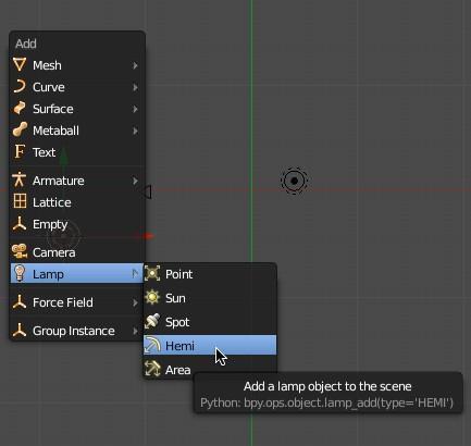
138 Press SHIFT-A and Add a Hemi Lamp.
139

140 Rendering: We are now ready to render the animation. Press NUMPAD-0 to go into Camera View. Press the Render context button in the Properties Editor. Under the Dimensions panel set the X dimension to 320 pixels and the Y dimension to 240 pixels. Set the Percentage control to 100 %.


141 In the Output panel, set the output to MPG. In the Encoding panel, set the format to MPEG-4


142 In the Output panel, click on the Output file icon. This opens Blender s File Browser. Type in a file name for the video file, and then choose where you want the MPPG movie file to be saved. (I choose my desktop)


143 Press the Accept button. This will produce a MPEG-4 video, 320 x 240 pixels and save it on my desktop. We can now render the animation. Click on the Animation button in the Render panel Blender s UV Image Editor Window will open and the animation will be rendered to a file. It will take a few minutes to render all 100 frames of the animation.


144 When it is finished rendering, you can play it back in Blender by pressing the Render button in the Information Editor Header and select Open GL Render Animation. You can also locate the video file in the output directory and play it in your MPEG-4 movie player. You can click on the window type button in the lower left corner of the display and return to the 3D viewport.

145 Save your Blender file CTRL-W.
NURBS Sailboat on Ocean (Modeling/Animation)
") Course: 3D Design Title: NURBS Sailboat Blender: Version 2.6X Level: Beginning Author; Neal Hirsig (nhirsig@tufts.edu) (April 2013) NURBS Sailboat on Ocean (Modeling/Animation) The objective of this PDF
Course: 3D Design Title: NURBS Sailboat Blender: Version 2.6X Level: Beginning Author; Neal Hirsig (nhirsig@tufts.edu) (April 2013) NURBS Sailboat on Ocean (Modeling/Animation) The objective of this PDF
Course: 3D Design Title: Mesh Modeling Hand Dropbox File: Hand.zip Blender: Version 2.41 Level: Beginning Author; Neal Hirsig
 Course: 3D Design Title: Mesh Modeling Hand Dropbox File: Hand.zip Blender: Version 2.41 Level: Beginning Author; Neal Hirsig (nhirsig@tufts.edu) Mesh Modeling Hand Open a new Blender file. We will be
Mesh Modeling Vase and Flower
 Course: 3D Design Title: Mesh Modeling Vase and Flower Dropbox File: VaseAndFlower.zip Blender: Version 2.45 Level: Beginning Author: Neal Hirsig (nhirsig@tufts.edu) Mesh Modeling Vase and Flower In this
Course: 3D Design Title: Mesh Modeling Shark Dropbox File: Shark.zip Blender: Version 2.45 Level: Beginning Author: Neal Hirsig
 Course: 3D Design Title: Mesh Modeling Shark Dropbox File: Shark.zip Blender: Version 2.45 Level: Beginning Author: Neal Hirsig (nhirsig@tufts.edu) Mesh Modeling Shark In this tutorial, we ll model a Shark.
Mesh Modeling Dice Boolean
 Course: 3D Design Title: Mesh Modeling Dice - Boolean Dropbox File: Dice.zip Blender: Version 2.41 Level: Beginning Author: Neal Hirsig (nhirsig@tufts.edu) Mesh Modeling Dice Boolean In this tutorial,
Open Blender and click anywhere to remove the Splash Screen.
 Photo Detail Modelling the 3D Industrial Building Open Blender and click anywhere to remove the Splash Screen. Click on the File Menu and select "Save as". Save the Blender file as Industrial_Building01.blend
Lathe Modeling Wine Glass
 Course: 3D Design Title: Bezier Curve Modeling Column Dropbox File: WineGlass.zip Blender: Version 2.41 Level: Beginning Author: Neal Hirsig (nhirsig@tufts.edu) Lathe Modeling Wine Glass In this tutorial,
Using Blender to Produce a Trainz Asset - Step 2-2 Add Materials and Texture (Continued)
") Apply Texture First, deselect everything in the 3D Editor Viewport by pressing the AKEY. When vertices, edges or faces are selected they appear orange. This key is also a toggle. Try pressing the AKEY
Apply Texture First, deselect everything in the 3D Editor Viewport by pressing the AKEY. When vertices, edges or faces are selected they appear orange. This key is also a toggle. Try pressing the AKEY
This is the opening view of blender.
 This is the opening view of blender. Note that interacting with Blender is a little different from other programs that you may be used to. For example, left clicking won t select objects on the scene,
Split the 3D Editor Viewport
 Split the 3D Editor Viewport To create two viewports where there was previously one (the 3D Editor Viewport), click on the cross hatch in the upper right hand corner of the 3D Editor Viewport. When the
Object Manipulation and Basic Animation
 Object Manipulation and Basic Animation By Immer Baldos This document is a tutorial on basic modeling and animation using Blender version 2.49b. The goals are to create a Windmill using blender s built-in
This lesson introduces Blender, covering the tools and concepts necessary to set up a minimal scene in virtual 3D space.
 3D Modeling with Blender: 01. Blender Basics Overview This lesson introduces Blender, covering the tools and concepts necessary to set up a minimal scene in virtual 3D space. Concepts Covered Blender s
Blender Notes. Introduction to Digital Modelling and Animation in Design Blender Tutorial - week 1 The Blender Interface and Basic Shapes
 Blender Notes Introduction to Digital Modelling and Animation in Design Blender Tutorial - week 1 The Blender Interface and Basic Shapes Introduction Blender is a powerful modeling, animation and rendering
Notes on Blender: By Matthew Evett
 Notes on Blender: By Matthew Evett A synopsis of the Wiki: http://en.wikibooks.org/wiki/blender_3d:_noob_to_pro The Blender GUI is implemented via opengl. Thus the GUI is not Windowsstandard. Can resize
Chapter 3- Creating & Editing Objects
 ` Chapter 3- Creating & Editing Objects Edit Mode- Mesh Editing Object Mode After you have created a mesh, you can go into Edit mode (Tab key or Mode option in window) and change its shape. In edit mode,
A Guide to Autodesk Maya 2015
 A Guide to Autodesk Maya 2015 Written by Mitchell Youngerman Table of Contents Layout of Toolbars...pg 1 Creating Objects...pg 2 Selecting & Deselecting Objects...pg 3 Changing Perspective... pg 4 Transforming
Basic Blender Commands This is just a partial list of Blender commands. Please visit the Blender.org website for more details.
 Basic Key Commands Basic Blender Commands This is just a partial list of Blender commands. Please visit the Blender.org website for more details. TAB key- Toggles between edit mode (vertex editing) and
Computer graphics Labs: Blender (1/3) Modelling, transparency and reflection
 Modelling, transparency and reflection") Computer graphics Labs: Blender (1/3) Modelling, transparency and reflection University of Liège Department of Aerospace and Mechanical engineering Designed with Blender 2.76b Introduction to the interface
Computer graphics Labs: Blender (1/3) Modelling, transparency and reflection University of Liège Department of Aerospace and Mechanical engineering Designed with Blender 2.76b Introduction to the interface
Week 1 The Blender Interface and Basic Shapes
 Week 1 The Blender Interface and Basic Shapes Blender Blender is an open-source 3d software that we will use for this class to create our 3d game. Blender is as powerful as 3d Studio Max and Maya and has
Blender Lesson Ceramic Bowl
 Blender Lesson Ceramic Bowl This lesson is going to show you how to create a ceramic looking bowl using the free program Blender. You will learn how to change the view, add, delete, scale and edit objects
Full Screen Layout. Main Menu Property-specific Options. Object Tools ( t ) Outliner. Object Properties ( n ) Properties Buttons
 Outliner. Object Properties ( n ) Properties Buttons") Object Tools ( t ) Full Screen Layout Main Menu Property-specific Options Object Properties ( n ) Properties Buttons Outliner 1 Animation Controls The Create and Add Menus 2 The Coordinate and Viewing
Object Tools ( t ) Full Screen Layout Main Menu Property-specific Options Object Properties ( n ) Properties Buttons Outliner 1 Animation Controls The Create and Add Menus 2 The Coordinate and Viewing
Using Blender to Create a Trainz Asset - Preparation
 Using Blender to Create a Trainz Asset - Preparation Project Folder It's a good idea to create a folder for each project to keep the various files associated with a project together. The folder can be
1st Point. 2nd Point. hold shift & drag along Y. Splines
 Splines STEP 1: open 3DS Max _ from the Command Panel under the Create tab click on Shapes (note: shapes are really Splines) _ under Object Type click on Ellipse STEP 2: Expand the Keyboard Entry tab type
solidthinking Environment...1 Modeling Views...5 Console...13 Selecting Objects...15 Working Modes...19 World Browser...25 Construction Tree...
 Copyright 1993-2009 solidthinking, Inc. All rights reserved. solidthinking and renderthinking are trademarks of solidthinking, Inc. All other trademarks or service marks are the property of their respective
3D Modeling Course Outline
 3D Modeling Course Outline Points Possible Course Hours Course Overview 4 Lab 1: Start the Course Identify computer requirements. Learn how to move through the course. Switch between windows. Lab 2: Set
Animation Basics. Learning Objectives
 Animation Basics Learning Objectives After completing this chapter, you will be able to: Work with the time slider Understand animation playback controls Understand animation and time controls Morph compound
Basic Blender Commands This is just a partial list of Blender commands. Please visit the Blender.org website for more details.
 Basic Key Commands Basic Blender Commands This is just a partial list of Blender commands. Please visit the Blender.org website for more details. TAB key- Toggles between edit mode (vertex editing) and
Author: John M Blain 2.54+
 Author: John M Blain 2.54+ Blender 3D Computer Modeling and Animation Blender 3D is a an open source freeware program maintained by the Blender Foundation. The program can be downloaded, free of charge,
https://blenderzen.com/
 Blender Shortcut Keys Cheat Sheet Blender is a vast multi-purpose program designed to do some very complex things. Luckily for us the creators of Blender simplified the interface and squeezed most commands
3D Design with 123D Design
 3D Design with 123D Design Introduction: 3D Design involves thinking and creating in 3 dimensions. x, y and z axis Working with 123D Design 123D Design is a 3D design software package from Autodesk. A
Maya 2014 Introduction to Maya
 Maya 2014 Introduction to Maya Maya is an incredibly powerful animation software that can be used to create almost anything you can imagine. The purpose of this document is to help you become familiar
Chapter 3- Creating & Editing Objects
 ` Chapter 3- Creating & Editing Objects Working with Basic Meshes Now that you can move around in Blender, let s start doing some basic building and shaping. In this chapter we will talk about creating
Autodesk Fusion 360 Training: The Future of Making Things Attendee Guide
 Autodesk Fusion 360 Training: The Future of Making Things Attendee Guide Abstract After completing this workshop, you will have a basic understanding of editing 3D models using Autodesk Fusion 360 TM to
SolidWorks Intro Part 1b
 SolidWorks Intro Part 1b Dave Touretzky and Susan Finger 1. Create a new part We ll create a CAD model of the 2 ½ D key fob below to make on the laser cutter. Select File New Templates IPSpart If the SolidWorks
SolidWorks 2½D Parts
 SolidWorks 2½D Parts IDeATe Laser Micro Part 1b Dave Touretzky and Susan Finger 1. Create a new part In this lab, you ll create a CAD model of the 2 ½ D key fob below to make on the laser cutter. Select
Reference Image. Source:
 Mesh Modeling By Immer Baldos This document is a tutorial on mesh modeling using Blender version 2.49b. The goal is to create a model of an elevator. This tutorial will tackle creating the elevator cart,
Chapter 3- Creating & Editing Objects
 Working with Basic Meshes Chapter 3- Creating & Editing Objects Now that we know how to move around in Blender, let s start doing some basic building and shaping. In this chapter we will talk about creating
Avid FX Tutorials. Understanding the Tutorial Exercises
 Avid FX Tutorials Understanding the Tutorial Exercises The following tutorial exercises provide step-by-step instructions for creating various kinds of effects, while exploring many aspects of the Avid
FLUID DESIGNER FOR 3D PRINTING Installing & Configuring Startup Screen
 FLUID DESIGNER FOR 3D PRINTING Installing & Configuring Startup Screen INSTALLING THE APPLICATION After downloading the file FluidDesigner3DPrinting.Zip from our web site you should install it in either
Polygon Modeling Basics Chapter 1 - Vertices
 Polygon Modeling Basics Chapter 1 - Vertices In this tutorial we will cover the basic tools necessary for Polygon Modeling using the Vertex sub-object selection. It is less of a how to tutorial and more
Autodesk Inventor Design Exercise 2: F1 Team Challenge Car Developed by Tim Varner Synergis Technologies
 Autodesk Inventor Design Exercise 2: F1 Team Challenge Car Developed by Tim Varner Synergis Technologies Tim Varner - 2004 The Inventor User Interface Command Panel Lists the commands that are currently
To familiarize of 3ds Max user interface and adapt a workflow based on preferences of navigating Autodesk 3D Max.
 Job No: 01 Duration: 8H Job Title: User interface overview Objective: To familiarize of 3ds Max user interface and adapt a workflow based on preferences of navigating Autodesk 3D Max. Students should be
Exercise Guide. Published: August MecSoft Corpotation
 VisualCAD Exercise Guide Published: August 2018 MecSoft Corpotation Copyright 1998-2018 VisualCAD 2018 Exercise Guide by Mecsoft Corporation User Notes: Contents 2 Table of Contents About this Guide 4
How to start your Texture Box Project!
 How to start your Texture Box Project! Shapes, naming surfaces, and textures. Lightwave 11.5 Part One: Create Your Shape Choose Start, Programs, New Tek, Lightwave and Modelor (the orange one). 1.In one
Getting Started with ShowcaseChapter1:
 Chapter 1 Getting Started with ShowcaseChapter1: In this chapter, you learn the purpose of Autodesk Showcase, about its interface, and how to import geometry and adjust imported geometry. Objectives After
WAYLAND FREE PUBLIC LIBRARY 3D Design and Printing Tutorial: Create a Keychain
 WAYLAND FREE PUBLIC LIBRARY 3D Design and Printing Tutorial: Create a Keychain Welcome! In this tutorial we will be creating a 3D printed keychain. You will personalize this name tag with text to make
Blender: Introduction, Modelling and Exporting
 Blender: Introduction, Modelling and Exporting 4076/GV07: Virtual Environments (VE) MSci 4th year, MSc VIVE, EngD Will Steptoe Room 6.22, Computer Science W.Steptoe@cs.ucl.ac.uk http://www.cs.ucl.ac.uk/staff/w.steptoe
User InterfaceChapter1:
 Chapter 1 User InterfaceChapter1: In this chapter you will learn about several aspects of the User Interface. You will learn about the overall layout of the UI, and then about the details of each element.
1.1: Introduction to Fusion 360
 .: Introduction to Fusion 360 Fusion 360 is a cloud- based CAD/CAM tool for collaborative product development. The tools in Fusion enable exploration and iteration on product ideas and collaboration within
User Interface Software Projects
 User Interface Software Projects Assoc. Professor Donald J. Patterson INF 134 Winter 2013 The author of this work license copyright to it according to the Creative Commons Attribution-Noncommercial-Share
By Roland Hess -- Based on the Blender Summer of Code tutorial by Michael Worcester
 Mesh Modeling Tutorial By Roland Hess -- Based on the Blender Summer of Code tutorial by Michael Worcester In the previous chapter, you learned how to manipulate objects in Blender. You've seen how to
Creating the Tilt Game with Blender 2.49b
 Creating the Tilt Game with Blender 2.49b Create a tilting platform. Start a new blend. Delete the default cube right click to select then press X and choose Erase Selected Object. Switch to Top view (NUM
What will you learn: A better understanding of 3 D space How to use keyframes Designing and planning an animation How to render animations
 Intro to Blender Introductory Animation Shane Trautsch Crestwood High School Welcome Back! Blender can also be used for animation. In this tutorial, you will learn how to create simple animations using
Chapter 9- Animation Basics
 Timing, Moving, Rotating and Scaling Now that we know how to make stuff and make it look good, it s time to figure out how to move it around in your scene. Another name for an animation is Interpolation
2.2 - Layouts. Bforartists Reference Manual - Copyright - This page is Public Domain
 2.2 - Layouts Introduction...2 Switching Layouts...2 Standard Layouts...3 3D View full...3 Animation...3 Compositing...3 Default...4 Motion Tracking...4 Scripting...4 UV Editing...5 Video Editing...5 Game
Blender. Basics. Second Edition. Classroom Tutorial Book. By James Chronister
 Blender Basics Second Edition Classroom Tutorial Book By James Chronister 2004, 2006 second edition by James Chronister. This document may be reproduced without permission from the author, but please let
Taking the Best Reference Photos
 Sides Three and Four To fill in the other two sides select the top vertice and the corners on a side where there is no face yet. Again, use FKEY to fill in a face. Repeat this for the last side to have
Actions and Graphs in Blender - Week 8
 Actions and Graphs in Blender - Week 8 Sculpt Tool Sculpting tools in Blender are very easy to use and they will help you create interesting effects and model characters when working with animation and
The Blender Quick Start Guide
 The Blender Quick Start Guide by Darrin Lile Blender Foundation Certified Trainer It takes time and practice to learn and internalize Blender s workflow. But given the right guidance, anyone can quickly
MatterHackers. How to make a 3D model using Google Earth. Written By: Ryan Lutz. How to make a 3D model using Google Earth data
 MatterHackers How to make a 3D model using Google Earth data Written By: Ryan Lutz 2017 matterhackers.dozuki.com Page 1 of 20 INTRODUCTION EDIT 7/25/17: Sadly, Sketchup has changed the map service they
Beginners Guide Maya. To be used next to Learning Maya 5 Foundation. 15 juni 2005 Clara Coepijn Raoul Franker
 Beginners Guide Maya To be used next to Learning Maya 5 Foundation 15 juni 2005 Clara Coepijn 0928283 Raoul Franker 1202596 Index Index 1 Introduction 2 The Interface 3 Main Shortcuts 4 Building a Character
Create a Rubber Duck. This tutorial shows you how to. Create simple surfaces. Rebuild a surface. Edit surface control points. Draw and project curves
 Page 1 of 24 Create a Rubber Duck This exercise focuses on the free form, squishy aspect. Unlike the flashlight model, the exact size and placement of the objects is not critical. The overall form is the
Lesson 1: Creating T- Spline Forms. In Samples section of your Data Panel, browse to: Fusion 101 Training > 03 Sculpt > 03_Sculpting_Introduction.
 3.1: Sculpting Sculpting in Fusion 360 allows for the intuitive freeform creation of organic solid bodies and surfaces by leveraging the T- Splines technology. In the Sculpt Workspace, you can rapidly
Autodesk Inventor - Basics Tutorial Exercise 1
 Autodesk Inventor - Basics Tutorial Exercise 1 Launch Inventor Professional 2015 1. Start a New part. Depending on how Inventor was installed, using this icon may get you an Inch or Metric file. To be
Working with the Dope Sheet Editor to speed up animation and reverse time.
 Bouncing a Ball Page 1 of 2 Tutorial Bouncing a Ball A bouncing ball is a common first project for new animators. This classic example is an excellent tool for explaining basic animation processes in 3ds
An Introduction to Maya. Maya. Used in industrial design, CAD, computer games and motion picture effects. The ambition is what get
 An Introduction to Maya Gustav Taxén gustavt@nada.kth.se 2D1640 Grafik och Interaktionsprogrammering VT 2006 Maya Used in industrial design, CAD, computer games and motion picture effects Special focus
Chapter 1- The Blender Interface
 The Blender Screen When I first looked at Blender and read some tutorials I thought that this looked easy and made sense. After taking the program for a test run, I decided to forget about it for a while
Lesson 11. Polygonal Spaceship
 11 Polygonal Spaceship In this lesson, you will build and texture map a polygonal spaceship. Starting with a polygonal cube, you will extrude facets until you have a completed ship. You will then be able
Tower Drawing. Learning how to combine shapes and lines
 Tower Drawing Learning how to combine shapes and lines 1) Go to Layout > Page Background. In the Options menu choose Solid and Ghost Green for a background color. This changes your workspace background
lundi 7 janvier 2002 Blender: tutorial: Building a Castle Page: 1
 lundi 7 janvier 2002 Blender: tutorial: Building a Castle Page: 1 www.blender.nl this document is online at http://www.blender.nl/showitem.php?id=4 Building a Castle 2000 07 19 Bart Veldhuizen id4 Introduction
Extrude. Taper. STEP 04: Ctrl +V _ select Copy from the clone window _ name the copy: Slabs Mesh _ click OK
 Extrude STEP 01: open the class-08 3ds Max file _ select the ellipse _ command panel / modifier list _ select Extrude _ set the extrusion Amount: 400 _ STEP 02: with the perspective viewport current press
4) Finish the spline here. To complete the spline, double click the last point or select the spline tool again.
 Finish the spline here. To complete the spline, double click the last point or select the spline tool again.") 1) Select the line tool 3) Move the cursor along the X direction (be careful to stay on the X axis alignment so that the line is perpendicular) and click for the second point of the line. Type 0.5 for
1) Select the line tool 3) Move the cursor along the X direction (be careful to stay on the X axis alignment so that the line is perpendicular) and click for the second point of the line. Type 0.5 for
AUTODESK FUSION 360 Designing a RC Car Body
 AUTODESK FUSION 360 Designing a RC Car Body Abstract This project explores how to use the sculpting tools available in Autodesk Fusion 360 Ultimate to design the body of a RC car. John Helfen john.helfen@autodesk.com
ROTOSCOPING AND MATTE PAINTING In Blender v2.48a
 In the world of Visual Effects, Rotoscoping, Matte Painting and Garbage Painting are necessary and complementary functions. They are used each time a cut-out in the image is necessary, to remove a background
In this tutorial, you will create a scene with sandman dispersing in sand, as shown in in the image below.
 Particle Flow In this tutorial, you will create a scene with sandman dispersing in sand, as shown in in the image below. Creating the Project Folder 1. Create a project folder with the name c17_tut1 at
5 Subdivision Surfaces
 5 Subdivision Surfaces In Maya, subdivision surfaces possess characteristics of both polygon and NURBS surface types. This hybrid surface type offers some features not offered by the other surface types.
Animating the Page IN THIS CHAPTER. Timelines and Frames
 e r ch02.fm Page 41 Friday, September 17, 1999 10:45 AM c h a p t 2 Animating the Page IN THIS CHAPTER Timelines and Frames Movement Tweening Shape Tweening Fading Recap Advanced Projects You have totally
Photography by Christina Sizemore. Mudbox Hotkeys
 Digital Sculpting with Mudbox FIG 2.12 Digital Images Are Composed of a Pixel Grid. Each Pixel Stores Information Like Color and Transparency. Mudbox Uses Digital Images as Stencils and Stamps and Creates
SketchUp Tool Basics
 SketchUp Tool Basics Open SketchUp Click the Start Button Click All Programs Open SketchUp Scroll Down to the SketchUp 2013 folder Click on the folder to open. Click on SketchUp. Set Up SketchUp (look
Step 2: Add Material and Texture
 Step 2: Add Material and Texture Material This part is easy as the Default Cube already has a material assigned. All we need to do is rename it as materials in Trainz assets need to have specific file
LOOSE FITTING CLOTHES
 LOOSE FITTING CLOTHES Begin by opening the basic box modeled figure 0-BasicFigure.blend. He s at https://users.soe.ucsc. edu/~yonge/05_homework_resources/. This exercise uses some retopology techniques
How to Create a Simple Animation Using MAYA
 How to Create a Simple Animation Using MAYA Jennifer Soltz July 29, 2011 0 Table of Contents Introduction Safety Information. 2. 3 What you need Materials Overview Diagram. 4. 4 Instructions Setup Modeling
3 Polygonal Modeling. Getting Started with Maya 103
 3 Polygonal Modeling In Maya, modeling refers to the process of creating virtual 3D surfaces for the characters and objects in the Maya scene. Surfaces play an important role in the overall Maya workflow
Maya tutorial. 1 Camera calibration
 Maya tutorial In this tutorial we will augment a real scene with virtual objects. This tutorial assumes that you have downloaded the file Maya.zip from the course web page and extracted it somewhere. 1
MAYA; AN INTRODUCTION TO MAYA; EndOfLine.info;
 MAYA; AN INTRODUCTION TO MAYA; EndOfLine.info; Maya is an intuitive modelling and animation software that relies on a different set of techniques and strategies than Rhinoceros. It is important to note
solidthinking Inspired Tutorials 2009 solidthinking, Inc. for Mac
 solidthinking Inspired Tutorials 2009 solidthinking, Inc. for Mac Table of Contents Quick Start Tutorials 3 Tutorial 11: Simple... Bridge 4 Tutorial 22: Desk... 12 Tutorial 33: Bookcase... 35 2 1 Quick
Detailed Table of content. 3D View by tools - Header. 3D View by tools - Header detailed
 3D View by tools - Header Detailed Table of content...1 Introduction...16 Header...16 All Modes - View Menu...17 All Modes - Navigation Menu...24 All Modes, all Object types - Show / Hide...29 Object Mode
Table of Contents. Blender...1. Blender's Unique Interface...2 Conventions Used in this Document...2
 Table of Contents Blender...1 Blender's Unique Interface...2 Conventions Used in this Document...2 Installing Blender on OSX...3 Downloading...3 Installing...4 Installing Blender on Ubuntu...6 Synaptic
ImageVis3D "Hands On"-Session
 ImageVis3D "Hands On"-Session Center for Integrative Biomedical Computing 2009 Workshop, Northeastern University 1 1. The current state of ImageVis3D Remember : 1. If you find any problems in ImageVis3D,
Modeling Level Design
 Summary This tutorial has introduced you to several of the tools you can use to make a low-polygon model with editable poly functionality. These tools can be adapted to the task of modeling any low-polygon
Solid Edge ST4 Update Training (Display)
") Solid Edge ST4 Update Training (Display) Presented By: Steve Webb Topic Middle Mouse Button Rotate Model Edge Display Display Performance View Style Thread and Weld Bead Texture Page 2 Middle Mouse Button
Solid Edge ST4 Update Training (Display) Presented By: Steve Webb Topic Middle Mouse Button Rotate Model Edge Display Display Performance View Style Thread and Weld Bead Texture Page 2 Middle Mouse Button
Transforming Objects and Components
 4 Transforming Objects and Components Arrow selection Lasso selection Paint selection Move Rotate Scale Universal Manipulator Soft Modification Show Manipulator Last tool used Figure 4.1 Maya s manipulation
Getting Started with Silo
 CHAPTER 1 Getting Started with Silo In this chapter, we discuss how to view, select, and manipulate models in Silo. If you are not familiar with Silo or polygon modeling, make sure to read the About Silo
-Remember to always hit Command + S every time you make a change to your project going forward.
 -Open Animate -Under Create New - Select ActionScript 3.0 -Choose Classic as the Design type located in the upper right corner -Animate workspace shows a toolbar, timeline, stage, and window tabs -From
ImageVis3D User's Manual
 ImageVis3D User's Manual 1 1. The current state of ImageVis3D Remember : 1. If ImageVis3D causes any kind of trouble, please report this to us! 2. We are still in the process of adding features to the
This view is called User Persp - perspective. It's good for rendering, but not for editing. Ortho will be better.
 Create a crate simple placeable in Blender. In this tutorial I'll show you, how to create and texture a simple placeable, without animations. Let's start. First thing is always to have an idea, how you
Chapter 1- The Blender Interface
 Chapter 1- The Blender Interface The Blender Screen Years ago, when I first looked at Blender and read some tutorials I thought that this looked easy and made sense. After taking the program for a test
XnView 1.9. a ZOOMERS guide. Introduction...2 Browser Mode... 5 Image View Mode...15 Printing Image Editing...28 Configuration...
 XnView 1.9 a ZOOMERS guide Introduction...2 Browser Mode... 5 Image View Mode...15 Printing... 22 Image Editing...28 Configuration... 36 Written by Chorlton Workshop for hsbp Introduction This is a guide
Using the CMA Warp Editor
 Using the CMA Warp Editor Overview The Warp Editor feature lets you adjust Axon HD, Axon HD Pro, DLHD or MMS100 output to match complex projection surfaces. These forms allow the projection to match irregular
Ultimate Game Host. Creating a basic model for garrysmod 13 using Blender 2.69 PDF Guide. Visit Us At: https://www.ultimategamehost.
 Ultimate Game Host Creating a basic model for garrysmod 13 using Blender 2.69 PDF Guide Visit Us At: https://www.ultimategamehost.com Creating A Basic Model for GarrysMod 13 using Blender 2.69 Overview: