Convergent Modeling and Reverse Engineering
|
|
|
- Linda Fox
- 6 years ago
- Views:
Transcription
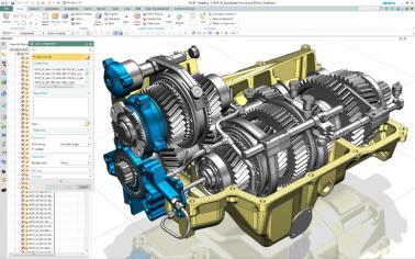
1 Convergent Modeling and Reverse Engineering 25 October 2017 Realize innovation.
2 Tod Parrella NX Design Product Management Product Engineering Solutions Realize innovation.

 NX 9 Subdivision Modeling NX 10 NX 11")
3 Siemens is investing in future modeling Continuous investment in current and future modeling technologies Single application environment for product to production design using any form of geometry Convergent Modeling Traditional Wireframe & Surface Modeling (NURBS) NX 9 Subdivision Modeling NX 10 NX 11 Page 3


4 Convergent Modeling technology Revolutionizing product development...with the Next Generation of Modeling to Production Capabilities Streamlined history based workflows without conversion! 3D printing of production parts and tooling Any design medium: Point Cloud, Meshes, NURBS, Simulation driven design and optimization Additive and subtractive manufacturing processes Page 4


5 Convergent Modeling technology Polygon modeling Scanning Convergent Modeling Design without conversion Additive & subtractive manufacturing Assembly design In-process work piece Topology optimization CAE Mesh Finite element analysis Tooling Motion volume 10x faster than traditional methods! Documentation Page 5
 as any other geometry!")
 Analysis (Measure, Weight, FEA, ) Assembly/DMU Business value")
6 Convergent Modeling technology NX investment overview Capabilities NX design can work with meshes (facets) as any other geometry! Direct use of scan/mesh data without conversion History based modeling with mesh geometry Associative wireframe and feature operations (Boolean, Mirror, Scale, ) Analysis (Measure, Weight, FEA, ) Assembly/DMU Business value Accelerate concept to production workflows No need for reverse engineering No expert knowledge required Page 6


7 Convergent body Convergent body = Body of mesh type Closed body = Convergent solid body Open body = Convergent sheet body Comprised of Convergent mesh faces and edges Body, Faces and Edges have full properties and attributes Mass, Volume, Area, Length, Color, Object properties Convergent body lives in Part History and partakes in full history based modeling (feature) operations Convergent Edges Convergent Faces Convergent Bodies Part History w/dependencies Page 7
8 Roadmap NX capabilities Import/Open Export/Save As Conversion Cleanup Std. Interactions Creation Operations Reconstruct CAD Analysis Assemblies 3D Printing JT, STL, VRML + various CAD and Neutral file format that support facets Convert Facet Body: Convert between NX, JT and Convergent mesh formats Facet Body from Body: Convert a std. b-rep CAD model to an NX or Convergent mesh body Snip, Decimate, Subdivide, Smooth, Fill Holes, Selection, Highlight, View Section, Transform, Snap To, Cut/Copy/Paste, Information, Wireframe / Shaded / Rendered Display Modes, Assign Material Extrude, Offset Surface, Thicken Body, Extract, WAVE Link, Pattern / Mirror, Projected / Intersected / Sectioned Curves, Boolean (Unite / Subtract / Intersect), Scale, Trim / Split, Trim Sheet, Divide Face, Extend Sheet, Offset Face, Shell, Merge (Disjoint / Overlapping / Touching) Detect primitives, Paint Facets, Rapid Surfacing, Fit Curves, Fit Surfaces, Refit Face, Extrude (to be retired), Measurements Distance, Angle, Face, Body,, Mass Properties, Facet Body Curvature, Object naming and display, Component selection, Find by size, Open by proximity, Replace, Product outline, Reference sets, Advanced weight management, Mirror, Make unique, Clearance analysis, Limited Collision detection (Move component & Assembly sequence, Assembly cut Send model directly to 3D printer via File > 3D Print (using Microsoft 3D Printing toolkit) Page 8


9 Consider the possibilities Allowing you to go further with polygons in the early stages of design Page 9


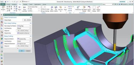
10 Roadmap NX accelerated capabilities Import/Export STL import / export dialog and functional improvements Snap to facet vertex to support design and applications Associative Facet Body from Body New feature support: Delete Body, New! Combine, Divide Face extension Replace Feature accepts convergent input Facet alignment commands Best fit Point Set to Point Set Multi-patch CAE Mesh on convergent MCD application Performance fixes Robustness of operators Imprint, Offset, Extension NX Open support Analysis tools CAE Analysis on a Convergent Body Draft Analysis Wall Thickness Analysis Deviation Analysis Check Wall Thickness Page 10


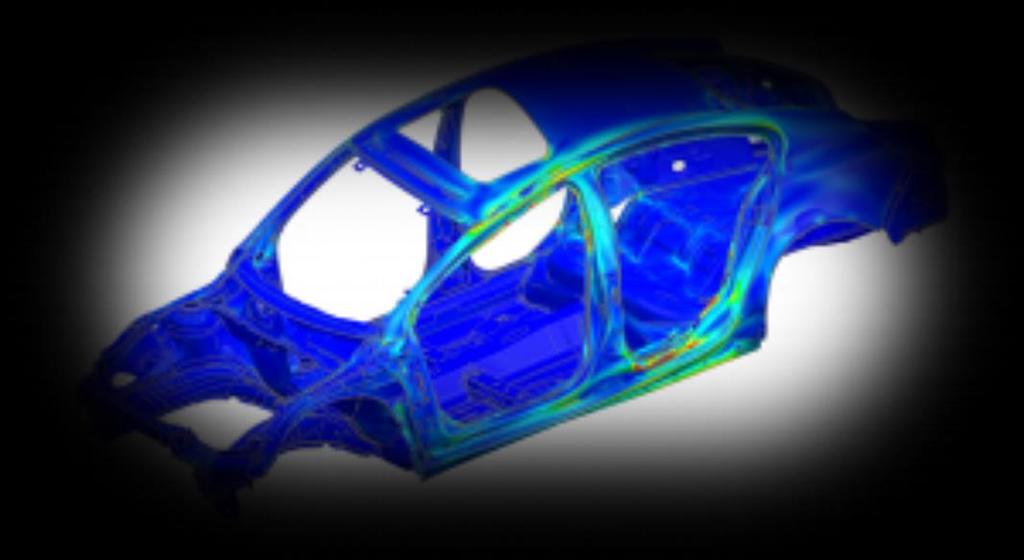
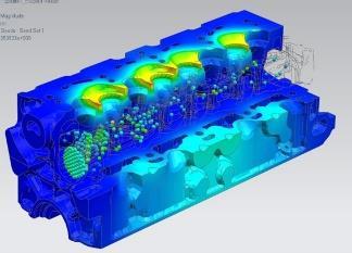
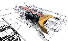
11 Consider the possibilities Scan to FEA and back to CAD without reverse engineering! Facet / mesh geometry History based modeling on facets FE mesh for Analysis Page 11


12 Impact of additive design to production processes End-to-end support to design, optimize and produce parts using additive manufacturing processes is revolutionizing the way future structures are developed Siemens is leading in the development of next generation software and processes to enable this shift CES 2017 Divergent 3D 3D Printed Blade Supercar customer Requirements driven design & validation Convergent Modeling TM technology Build processing & validation Design rules & validation Lightweight structure design & optimization Performance Optimization & validation Page 12

13 Roadmap NX Design for additive checkers Analysis > Design Validation for Additive Manufacturing Check Minimum Wall Thickness Check Maximum Overhand Angle Check Model within Printable Volume Check Wholly Enclosed Volume NX nx_additive_design license Page 13


14 Consider the possibilities Scan to print Scan Analyze / Optimize Create / Modify Print Page 14


15 Roadmap NX Lightweight structure design Fill a solid volume with lattices for part light weighting and material reduction while supporting the required loads License nx_additive_lattice Page 15
16 NX


17 NX Workflow focus Mesh prep for molding / 3D printing New modeling / Design with meshes Lightweight structure design Workflow integration Page 17
18 Convergent Modeling technology Update NX Capabilities Import / Export Conversion Cleanup Mesh Operators Std. Interactions Creation Operations Reconstruct CAD Lattice Design Analysis JT, STL, VRML + various CAD and Neutral file format that support facets Convert Facet Body (Convert between NX, JT and Convergent mesh formats), Facet Body from Body Associative (Convert a std. b-rep CAD model to an NX or Convergent mesh body) Clean-up Facet Body, Snip, Decimate, Subdivide, Smooth, Fill Holes, Facet Modeling Task Environment, Facet Selection Block, Create Transition, Local Offset, Facet Offset, Fix Undercuts, Adjust Minimum Radius, Create Topology (Divide Facet Faces, Merge Facet Faces) Selection, Highlight, View Section, Transform, Snap To, Cut/Copy/Paste, Information, Wireframe / Shaded / Face Analysis / Rendered Display Modes, Perspective, Assign Material Extrude w/offsets, Offset Surface w/extension, Thicken Body, Extract, WAVE Link, Pattern / Mirror, Curve on Surface, Projected / Intersected / Sectioned Curves, Hole, Body by Equation, Text Boolean (Unite / Subtract / Intersect) w/region Selection, Scale, Trim / Split Body w/extrusion type, Trim Sheet w/imprint Completion, Divide Face, Extend Sheet, Offset Face, Shell, Merge (Disjoint / Overlapping / Touching), Delete Body, Combine w/mixed mode support, Sew, Edge Blend, Global Shaping, Trim and Extend Alignment (Multipatch, Best Fit, Point Set), Detect primitives, Paint Facets, Rapid Surfacing, Fit Curves, Fit Surfaces, Refit Face, Extrude (to be retired) Rectangular unit cell lattice, Surface conformal lattice Measurements Distance, Angle, Face, Body,, Mass Properties, Facet Body Curvature, Draft Analysis, Check Wall Thickness Analysis, Deviation Gauge, Face Analysis (Radius, Slope, Distance, Reflection), AM Wall Thickness, AM Overhang Angle, AM Printable Volume, AM Wholly Enclosed Volumes Page 18
19 Convergent Modeling technology Update NX Capabilities Assemblies 3D Printing PMI Drafting CAE Object naming and display, Component selection, Find by size, Open by proximity, Replace, Product outline, Reference sets, Advanced weight management, Mirror, Make unique, Clearance analysis, Limited Collision detection (Move component & Assembly sequence, Assembly cut Send model directly to 3D printer via File > 3D Print (using Microsoft 3D Printing toolkit) Section View, Linear & Angular Dimensions, Annotation, View Creation Wizard, Base Views, Projected Views, Detail Views, View Break, Section Line, Section View, Linear & Angular Dimensions, Annotation, Mesh a Convergent Body, Page 19


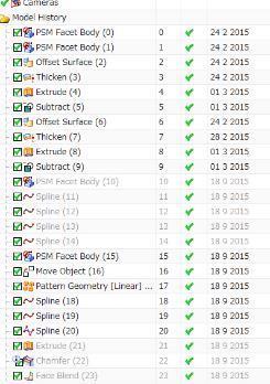
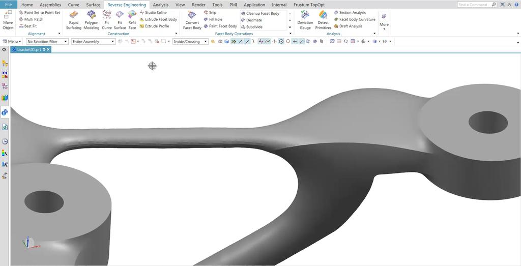
20 Polygon Modeling task environment On the Reverse Engineering tab Select 1 or multiple bodies Capability Dedicated environment for history free editing of convergent / facet geometry Will roll back to timestamp of convergent body if downstream history exists To make history free edits on a history based convergent body, first create a non-associative copy Page 20
")
21 Polygon Modeling task environment Value Easy to use, dedicated environment for history free editing within a history based modeler (very much like NX Realize Shape) Page 21
 Use Show")

22 Cleanup Facet Body (Analyze) Use Show Results to Preview the Analysis Page 22
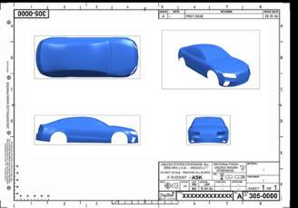
23 Cleanup Facet Body (Repair) Use Show Results to Preview the Repair Page 23


24 Facet Selection Single Facet Single Rectangle Circle Lasso Polygon Rough Brush Selects within and crossing the brush Color Region Face Facets All facets of face Employed in: Snip Decimate Subdivide Smooth Paint Facet Body Divide Facet Faces Adjust Minimum Radius Local Offset Fine Brush Selects within the brush Flood Fill Fills within a selected boundary Page 24


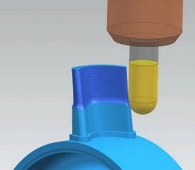
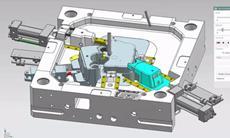
25 Mesh Prep for Molding / 3D Printing Create Transition Fix Undercuts Page 25 License nx_polygon_modeling license


26 Mesh Prep for Molding / 3D Printing Local Offset Adjust Minimum Radius Page 26 License nx_polygon_modeling license

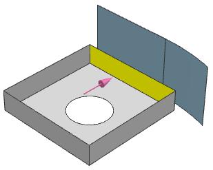
27 New Modeling / Design with Meshes Global Shaping Page 27

28 New Modeling / Design with Meshes Hole Page 28


29 Lightweight structure design Surface conformal lattice Create lattices that follow the design form and supports the required loads Page 29 License nx_additive_lattice

30 Workflow Integration PMI and Drafting Documentation Page 30


31 Engineering driven Design with Symbolica Page 31

32 Workflow Integration Creation of Topology for FEA and CAM Page 32 License nx_polygon_modeling license

33 Divide / Merge Facet Faces Page 33 License nx_polygon_modeling
34 Demonstration Page 34

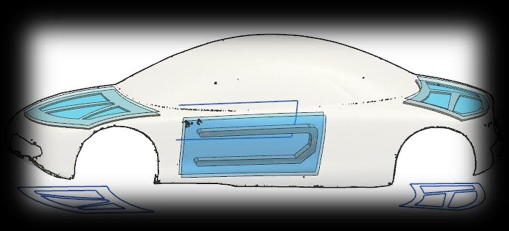
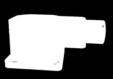
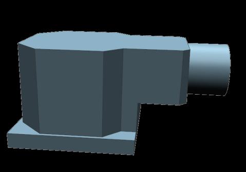
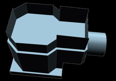
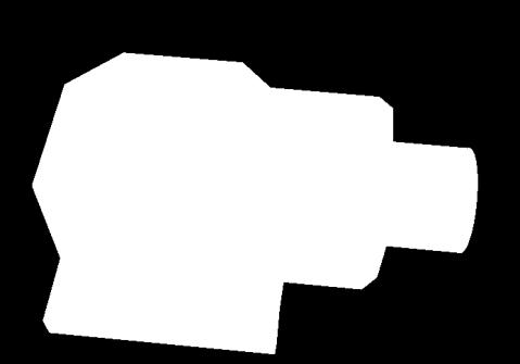
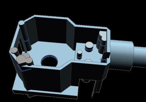
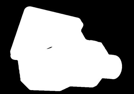
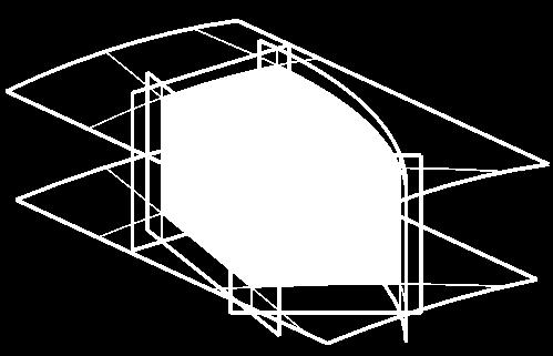
35 Apply organic shape onto product CAD model Page 35

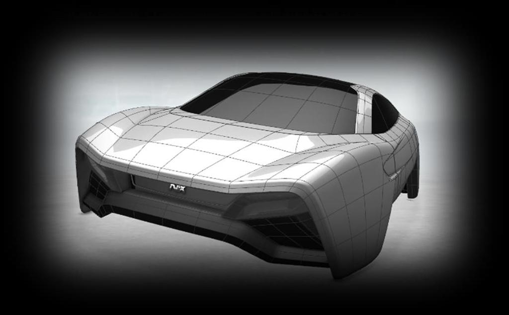
36 Apply textures and graphics onto product CAD model Page 36


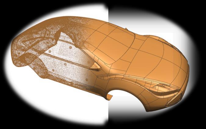
37 Morph large, complex CAD model Page 37
38 Demo As such, presentations help define the company s reputation and provide both internal and external orientation. Page 38
39 Reverse Engineering Knowledge Theatre Realize innovation.
40 Tod Parrella NX Design Product Management Product Engineering Solutions Realize innovation.
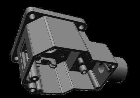
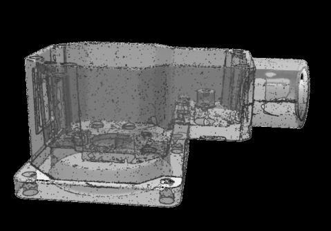
41 Reverse Engineering Workflow STL Align Fit Surface Outside Body Inside Body Compare Details Done! Add Blends Edge Model Page 41


42 Underlying Technology Shape Detection Analytic Based Plane, Cylinder, Cone, Sphere Product Curvature Concave, Convex Scanned STL Detected Primitives Page 42


43 Underlying Technology Surface Fitting Analytic Fitting Freeform Fitting Rapid Surfacing N-Sided Fitting Page 43


44 Leverage the power of NX Modeling in the RE workflow Combining Sheets Replace Face Corner Blending Synchronous Rotate Synchronous Offset Page 44

![/ Printed ±0.05 [mm] ±0.](/docs-images/74/70346837/images/45-1.jpg "02 [mm] ±0.")
45 Deviation Gauge Compare As Modeled to As Scanned / Printed ±0.05 [mm] ±0.02 [mm] ±0.01 [mm] Page 45


46 Morphing Product CAD Shape Morphing Create Compensated CAD Model to Polygon. Fit CAD Model to Polygon. Based on CAE Analysis of Spring back or Die Shrinkage or Real Physical Product Scan Data Business Value Modify As Designed to reflect changed needed to account for manufacturing process variation Modify As Designed to reflect how parts are being successfully produced on the shop floor Page 46


47 NX Reverse Engineering Working Time on Before/After NX 10 Model A Model B Model C Model D Model Shape Overview Working Time, Before Customer Estimation 210 Features 286 Face 240 Features 286 Faces 295 Features 179 Faces 2700 Features 2852 Faces 1 Week 1 Week 1 Week 3 Weeks Working Time w/nx RE Half Day: 2 or 3 hours Half Day: 2 or 3 hours Half Day: 3 or 4 hours 4 days, 30 hours Page 47
48 Demo As such, presentations help define the company s reputation and provide both internal and external orientation. Page 48
49 Thank you.
Topology Optimization for Designers
 TM Topology Optimization for Designers Siemens AG 2016 Realize innovation. Topology Optimization for Designers Product Features Uses a different approach than traditional Topology Optimization solutions.
Geometric Modeling Topics
 Geometric Modeling Topics George Allen, george.allen@siemens.com Outline General background Convergent modeling Multi-material objects Giga-face lattices Page 2 Boundary Representation (b-rep) Topology
3D PRINTING AND CONVERGENT MODELING IN NX Patrick Barrett
 3D PRINTING AND CONVERGENT MODELING IN NX 11.0.1 Patrick Barrett www.appliedcax.com Patrick Barrett Who Am I Started using UG in 1996 Started Sherpa Design in 2001 Designed many things for many different
Introduction to ANSYS DesignModeler
 Lecture 5 Modeling 14. 5 Release Introduction to ANSYS DesignModeler 2012 ANSYS, Inc. November 20, 2012 1 Release 14.5 Preprocessing Workflow Geometry Creation OR Geometry Import Geometry Operations Meshing
Reverse Engineering Convert STL mesh data to a Solid Edge part model and speed up Product Development.
 Reverse Engineering Convert STL mesh data to a Solid Edge part model and speed up Product Development. Realize innovation. Reverse Engineering Why Reverse Engineering? Convert an existing physical part
Freeform / Freeform PLUS
 Freeform / Freeform PLUS WORKING WITH FREEFORM Work from Coarse Clay to Fine When creating new models from scratch, it is best to first create a rough shape using a coarse clay setting such as Rough Shape
#SEU Welcome! Solid Edge University 2016
 #SEU 2016 Welcome! Solid Edge University 2016 Realize innovation. Reverse Engineering Convert STL mesh data to a Solid Edge part model and speed up Product Development. Realize innovation. About me Sandeep
L1 - Introduction. Contents. Introduction of CAD/CAM system Components of CAD/CAM systems Basic concepts of graphics programming
 L1 - Introduction Contents Introduction of CAD/CAM system Components of CAD/CAM systems Basic concepts of graphics programming 1 Definitions Computer-Aided Design (CAD) The technology concerned with the
Input CAD Solid Model Assemblies - Split into separate Part Files. DXF, IGES WMF, EMF STL, VDA, Rhino Parasolid, ACIS
 General NC File Output List NC Code Post Processor Selection Printer/Plotter Output Insert Existing Drawing File Input NC Code as Geometry or Tool Paths Input Raster Image Files Report Creator and Designer
Character Modeling COPYRIGHTED MATERIAL
 38 Character Modeling p a r t _ 1 COPYRIGHTED MATERIAL 39 Character Modeling Character Modeling 40 1Subdivision & Polygon Modeling Many of Maya's features have seen great improvements in recent updates
4) Finish the spline here. To complete the spline, double click the last point or select the spline tool again.
 Finish the spline here. To complete the spline, double click the last point or select the spline tool again.") 1) Select the line tool 3) Move the cursor along the X direction (be careful to stay on the X axis alignment so that the line is perpendicular) and click for the second point of the line. Type 0.5 for
1) Select the line tool 3) Move the cursor along the X direction (be careful to stay on the X axis alignment so that the line is perpendicular) and click for the second point of the line. Type 0.5 for
NX Strategy & Roadmap
 Speed of Innovation >>> NX Strategy & Roadmap Mike Rebrukh Product Management Paul Bevan Product Marketing Realize innovation. NX Release Roadmap NX 11.0 Convergent Modeling Technology Additional Touch
Images from 3D Creative Magazine. 3D Modelling Systems
 Images from 3D Creative Magazine 3D Modelling Systems Contents Reference & Accuracy 3D Primitives Transforms Move (Translate) Rotate Scale Mirror Align 3D Booleans Deforms Bend Taper Skew Twist Squash
CATIA V5-6R2015 Product Enhancement Overview
 Click to edit Master title style CATIA V5-6R2015 Product Enhancement Overview John Montoya, PLM Technical Support March 2015 1 2010 Inceptra LLC. All rights reserved. Overview of Enhanced Products Overview
Nouveautés ANSYS pour le calcul structurel et l impression 3D. CADFEM 2017 ANSYS Additive Manufacturing
 Titelmasterformat Journée Technologique durch AddiPole Klicken bearbeiten Nouveautés ANSYS pour le calcul structurel et l impression 3D Titelmasterformat Structural design with durch ANSYS Klicken bearbeiten
Geometric Modeling. Introduction
 Geometric Modeling Introduction Geometric modeling is as important to CAD as governing equilibrium equations to classical engineering fields as mechanics and thermal fluids. intelligent decision on the
Geometry Definition in the ADINA User Interface (AUI) Daniel Jose Payen, Ph.D. March 7, 2016
 Daniel Jose Payen, Ph.D. March 7, 2016") Geometry Definition in the ADINA User Interface (AUI) Daniel Jose Payen, Ph.D. March 7, 2016 ADINA R&D, Inc., 2016 1 Topics Presented ADINA에서쓰이는 Geometry 종류 Simple (AUI) geometry ADINA-M geometry ADINA-M
Geometry Definition in the ADINA User Interface (AUI) Daniel Jose Payen, Ph.D. March 7, 2016 ADINA R&D, Inc., 2016 1 Topics Presented ADINA에서쓰이는 Geometry 종류 Simple (AUI) geometry ADINA-M geometry ADINA-M
3D Modeling and Design Glossary - Beginner
 3D Modeling and Design Glossary - Beginner Align: to place or arrange (things) in a straight line. To use the Align tool, select at least two objects by Shift left-clicking on them or by dragging a box
ARCHITECTURE & GAMES. A is for Architect Simple Mass Modeling FORM & SPACE. Industry Careers Framework. Applied. Getting Started.
 A is for Architect Simple Mass Modeling One of the first introductions to form and space usually comes at a very early age. As an infant, you might have played with building blocks to help hone your motor
Sculpting 3D Models. Glossary
 A Array An array clones copies of an object in a pattern, such as in rows and columns, or in a circle. Each object in an array can be transformed individually. Array Flyout Array flyout is available in
CATIA V5 Parametric Surface Modeling
 CATIA V5 Parametric Surface Modeling Version 5 Release 16 A- 1 Toolbars in A B A. Wireframe: Create 3D curves / lines/ points/ plane B. Surfaces: Create surfaces C. Operations: Join surfaces, Split & Trim
Chapter 9 3D Modeling
 Chapter 9 3D Modeling Copyright The McGraw-Hill Companies, Inc. Permission required for reproduction or display. 3D Modeling Snapshot Since Mid 1980 s become common place in industry Software Types Wireframe
Autodesk Fusion 360 Training: The Future of Making Things Attendee Guide
 Autodesk Fusion 360 Training: The Future of Making Things Attendee Guide Abstract After completing this workshop, you will have a basic understanding of editing 3D models using Autodesk Fusion 360 TM to
All-in-One Software Solution for Metal Additive Manufacturing
 All-in-One Software Solution for Metal Additive Manufacturing What Makes 3DXpert Ideal for Metal Additive Manufacturing? Specialized Requirements Call for Specialized Software Metal Additive Manufacturing
NX Advanced 5-Axis Machining
 Siemens PLM Software NX Advanced 5-Axis Machining Benefits Automated hole making capability speeds common processes Boundary-based cutting provides flexibility to cut on minimal geometry Solids-based cutting
CATIA V5R21 - FACT SHEET
 CATIA V5R21 - FACT SHEET Introduction What s New at a Glance Overview Detailed Description INTRODUCTION CATIA V5 is the leading solution for product success. It addresses all manufacturing organizations;
What's New in NX 11 for Design Engineering
 What's New in NX 11 for Design Engineering NX 11 for Design Productivity Convergent Modeling Many industries use scanned 3D data as part of their design processes. If you have worked with this data in
Version 2011 R1 - Router
 GENERAL NC File Output List NC Code Post Processor Selection Printer/Plotter Output Insert Existing Drawing File Input NC Code as Geometry or Tool Paths Input Raster Image Files Convert Raster to Vector
SOLIDWORKS 2016: A Power Guide for Beginners and Intermediate Users
 SOLIDWORKS 2016: A Power Guide for Beginners and Intermediate Users The premium provider of learning products and solutions www.cadartifex.com Table of Contents Dedication... 3 Preface... 15 Part 1. Introducing
2D CAD. Courseware Issued: DURATION: 64 hrs
 2D CAD Introduction File management Orthographic drawings View management Display management Layer management Selection methods Parametric drawings Symbol creation using block BOM / Joinery details creation
Page 1 of 7. Please contact you netfabb distributor for more information and ordering.
 Page 1 of 7 New Features in netfabb Professional 5 Overview based on netfabb Professional 5.1 including most important features from previous netfabb versions Usability improvements Automatic Repair one-click
SpaceClaim 2015 Release Notes. SpaceClaim 2015 SP1. Release Notes
 SpaceClaim 2015 Release Notes SpaceClaim 2015 SP1 Release Notes Table of Contents SpaceClaim 2015 Release Notes SpaceClaim 2015 Enhancements Overview... 1 Notes... 2 SP1 Items... 3 STL Modeling... 3 Vectorize
form.z features Comparison Chart
 form.z features Comparison Chart Modeling Accurate robust internal representation of data including 3D solids, surfaces, trimmed surfaces, NURBS and parametric representations. ACIS modeling engine provides
Preparing Models for CAE and MFG Applications
 Preparing Models for CAE and MFG Applications Closing the Gap Abdul Shammaa Elysium Inc. GPDIS_2013.ppt 1 The Gap CAD models are often not readily usable by downstream applications A mathematically valid
Introduction to Solid Modeling Parametric Modeling. Mechanical Engineering Dept.
 Introduction to Solid Modeling Parametric Modeling 1 Why draw 3D Models? 3D models are easier to interpret. Simulation under real-life conditions. Less expensive than building a physical model. 3D models
COMPUTER AIDED ARCHITECTURAL GRAPHICS FFD 201/Fall 2013 HAND OUT 1 : INTRODUCTION TO 3D
 COMPUTER AIDED ARCHITECTURAL GRAPHICS FFD 201/Fall 2013 INSTRUCTORS E-MAIL ADDRESS OFFICE HOURS Özgür Genca ozgurgenca@gmail.com part time Tuba Doğu tubadogu@gmail.com part time Şebnem Yanç Demirkan sebnem.demirkan@gmail.com
Lesson 4: Surface Re-limitation and Connection
 Lesson 4: Surface Re-limitation and Connection In this lesson you will learn how to limit the surfaces and form connection between the surfaces. Lesson contents: Case Study: Surface Re-limitation and Connection
What s New Topics in 3.5.1: 1. User Interface 5. Reference Geometry 2. Display 6. Sketch 3. livetransfer 7. Surface / Solid 4. Scan Tools 8.
 ]^ New Release Turning Measured Points into Solid Models What s New Topics in 3.5.1: 1. User Interface 5. Reference Geometry 2. Display 6. Sketch 3. livetransfer 7. Surface / Solid 4. Scan Tools 8. Measure
NX MACH design solutions
 Siemens PLM Software MACH design solutions Power, flexibility and control improve design productivity Benefits Boosts product design efficiency Accelerates mechanical design processes Improves collaboration
Autodesk Alias Design Drives Success
 Autodesk Alias Design Drives Success ( 주 ) 유써브 http://www.u-serv.co.kr Image courtesy of AutoHorizons Foundation and Delineate Design Autodesk Drives Alias Success 2012 Innovate Ahead of the Curve Autodesk
Geometric Modeling Systems
 Geometric Modeling Systems Wireframe Modeling use lines/curves and points for 2D or 3D largely replaced by surface and solid models Surface Modeling wireframe information plus surface definitions supports
Introduction to the Mathematical Concepts of CATIA V5
 CATIA V5 Training Foils Introduction to the Mathematical Concepts of CATIA V5 Version 5 Release 19 January 2009 EDU_CAT_EN_MTH_FI_V5R19 1 About this course Objectives of the course Upon completion of this
Engineering Drawing II
 Instructional Unit Basic Shading and Rendering -Basic Shading -Students will be able -Demonstrate the ability Class Discussions 3.1.12.B, -Basic Rendering to shade a 3D model to apply shading to a 3D 3.2.12.C,
NX Mach Series Industrial Design
 Mach Series Industrial Design Features Provides tools for creating, modifying and analyzing free form and aesthetically pleasing surfaces and shapes Allows for conceptual models as well as for producing
The Beret-Palette Ring. Designed by Luiz Maia
 The Beret-Palette Ring Designed by Luiz Maia Table of Contents Part I Description of the model.p. 3 Part II Building the ring..p. 4-25 The beret-palette....p. 4-11 The shank/paintbrush p. 12 The handle
Exercise Guide. Published: August MecSoft Corpotation
 VisualCAD Exercise Guide Published: August 2018 MecSoft Corpotation Copyright 1998-2018 VisualCAD 2018 Exercise Guide by Mecsoft Corporation User Notes: Contents 2 Table of Contents About this Guide 4
Lesson 5 Solid Modeling - Constructive Solid Geometry
 AutoCAD 2000i Tutorial 5-1 Lesson 5 Solid Modeling - Constructive Solid Geometry Understand the Constructive Solid Geometry Concept. Create a Binary Tree. Understand the basic Boolean Operations. Create
Creating Mold Bases with NX Expressions
 Creating Mold Bases with NX Expressions By Murat Ugur, April 29, 2013 In this article, I introduce Siemens PLM Systems NX expressions, part families, and the visual parameter editor. I show how to create
Customized Pre/post-processor for DIANA. FX for DIANA
 Customized Pre/post-processor for DIANA FX for DIANA About FX4D for DIANA FX4D is a general purpose pre/post-processor for CAE simulation. FX4D has been specialized for civil/architectural applications.
Chapter 2: Rhino Objects
 The fundamental geometric objects in Rhino are points, curves, surfaces, polysurfaces, extrusion objects, and polygon mesh objects. Why NURBS modeling NURBS (non-uniform rational B-splines) are mathematical
MecSoft Corporation 18019, Sky Park Circle, Suite K-L Irvine, CA 92614, USA
 MecSoft Corporation 18019, Sky Park Circle, Suite K-L Irvine, CA 92614, USA PHONE: (949) 654-8163 FAX: (949) 654-8164 E-MAIL: sales@mecsoft.com www.mecsoft.com What s New In VisualCAM 1.0 & VisualMILL
UG Re-mastering for Automotive Engineering. 19 th October Siemens PLM Software
 UG Re-mastering for Automotive Engineering 19 th October 2007 Modeling Issues Re-mastering Takes time Release of prototype data happens soon. Skill set not fully developed users need time. May not be necessary.
SOLIDWORKS 2019 Advanced Techniques
 SOLIDWORKS 2019 Advanced Techniques Mastering Parts, Surfaces, Sheet Metal, SimulationXpress, Top Down Assemblies, Core & Cavity Molds Paul Tran CSWE, CSWI SDC PUBLICATIONS Better Textbooks. Lower Prices.
Feature and Topology Detection
 Feature and Topology Detection Greater possibilities with Capvidia extension and PARTsolutions Cadenas Industry Forum February 5th, 2015 Thomas Tillmann Capvidia GmbH Agenda Company Overview Application
BobCAD CAM V25 4 Axis Standard Posted by Al /09/20 22:03
 BobCAD CAM V25 4 Axis Standard Posted by Al - 2012/09/20 22:03 Many BobCAD CAM clients that run a 4 axis have requested to work directly with Solids or STL files. In the past we only offered 4 axis indexing
CGS 3220 Lecture 13 Polygonal Character Modeling
 CGS 3220 Lecture 13 Polygonal Character Modeling Introduction to Computer Aided Modeling Instructor: Brent Rossen Overview Box modeling Polygon proxy Mirroring Polygonal components Topology editing Procedural
A Comprehensive Introduction to SolidWorks 2011
 A Comprehensive Introduction to SolidWorks 2011 Godfrey Onwubolu, Ph.D. SDC PUBLICATIONS www.sdcpublications.com Schroff Development Corporation Chapter 2 Geometric Construction Tools Objectives: When
LAB # 2 3D Modeling, Properties Commands & Attributes
 COMSATS Institute of Information Technology Electrical Engineering Department (Islamabad Campus) LAB # 2 3D Modeling, Properties Commands & Attributes Designed by Syed Muzahir Abbas 1 1. Overview of the
PTC CREO. ESSENTIALS PACKAGES Powerful 3D CAD solutions optimized for your product development tasks. PTC Creo Essentials Packages
 PTC CREO PACKAGES Powerful 3D CAD solutions optimized for your product development tasks Product design firms and manufacturing companies are under constant pressure to develop more products in less time,
AutoCAD for Engineers and Designers, 21st Edition. (3D and Advanced)
") AutoCAD 2015 for Engineers and Designers, 21st Edition (3D and Advanced) CADCIM Technologies 525 St. Andrews Drive Schererville, IN 46375, USA (www.cadcim.com) Contributing Author Sham Tickoo Professor
AutoCAD 2015 for Engineers and Designers, 21st Edition (3D and Advanced) CADCIM Technologies 525 St. Andrews Drive Schererville, IN 46375, USA (www.cadcim.com) Contributing Author Sham Tickoo Professor
Page 1 of 6
 Page 1 of 6 www.netfabb.com netfabb Professional Features and Package Types netfabb Professional 5.2 netfabb Small Business netfabb Business Edition netfabb Professional is the most easy to use fully professional
Meshing in STAR-CCM+: Recent Advances Aly Khawaja
 Meshing in STAR-CCM+: Recent Advances Aly Khawaja Outline STAR-CCM+: a complete simulation workflow Emphasis on pre-processing technology Recent advances in surface preparation and meshing Continue to
ZW3D 2011 New Features
 ZW3D 2011 New Features Table of Contents Introduction to ZW3D 2011... 1 1. Modeling Innovations... 2 1.1 SmoothFlow Direct Edit... 2 1.2 Dynamic Dimensions... 2 1.3 QuickEdit... 3 1.4 SmartPick... 4 1.5
DIANA. Finite Element Analysis. Civil Engineering Geotechnical Engineering Petroleum Engineering
 DIANA Finite Element Analysis Civil Engineering Geotechnical Engineering Petroleum Engineering NOW Advancing in new numerical analysis techniques Developing state-of-the-art solution for engineering applications
5 Subdivision Surfaces
 5 Subdivision Surfaces In Maya, subdivision surfaces possess characteristics of both polygon and NURBS surface types. This hybrid surface type offers some features not offered by the other surface types.
Each trainee receives the official 260 page courseware as part of attending this course.
 Level 1 NURBS modelling with Rhino Course Outline This course is for anyone new, or nearly new, to Rhino. Recognised as THE introductory course for Rhino, all trainees receive an Official Certificate on
Dave s Phenomenal Maya Cheat Sheet Polygon Modeling Menu Set By David Schneider
 Dave s Phenomenal Maya Cheat Sheet Polygon Modeling Menu Set By David Schneider POLYGONS NURBS to Polygons This allows the user to change the objects created with NURBS into polygons so that polygon tools
Guide for Geomagic Design X 3D Scan Data Cleanup and Editing. General Information
 Guide for Geomagic Design X 3D Scan Data Cleanup and Editing General Information Geomagic Design X (formerly Rapidform XOR) is an extremely powerful reverse engineering and 3D modeling software that combines
CREO ENGINEER PACKAGES. 3D CAD solutions optimized for your product development tasks
 CREO ENGINEER PACKAGES 3D CAD solutions optimized for your product development tasks From the smallest product design firm to the largest, manufacturing organizations are under constant pressure to develop
Page 1. Area-Subdivision Algorithms z-buffer Algorithm List Priority Algorithms BSP (Binary Space Partitioning Tree) Scan-line Algorithms
 Scan-line Algorithms") Visible Surface Determination Visibility Culling Area-Subdivision Algorithms z-buffer Algorithm List Priority Algorithms BSP (Binary Space Partitioning Tree) Scan-line Algorithms Divide-and-conquer strategy:
Visible Surface Determination Visibility Culling Area-Subdivision Algorithms z-buffer Algorithm List Priority Algorithms BSP (Binary Space Partitioning Tree) Scan-line Algorithms Divide-and-conquer strategy:
Additive manufacturing with NX
 Additive manufacturing with processes. By using you have the power to drive the latest additive manu facturing equipment, including powder bed 3D printers. Delivering design, simulation and manufacturing
CAD INTEROPERABILITY SOFTWARE SUITE
 CAD INTEROPERABILITY SOFTWARE SUITE 1 3D_Evolution Conversion Engine is today s leading MCAD collaboration suite. Designed for a seamless, integrated process, it is the ideal enhancement for your PLM environment.
Advanced Webinar. Date: December 8, 2011 Topic: General Use of midas GTS (Part I) Presenter: Abid Ali, Geotechnical Engineer
 Presenter: Abid Ali, Geotechnical Engineer") midas GTS Advanced Webinar Date: December 8, 2011 Topic: General Use of midas GTS (Part I) Presenter: Abid Ali, Geotechnical Engineer Bridging Your Innovations to Realities Contents: 1. Introduction 2.
midas GTS Advanced Webinar Date: December 8, 2011 Topic: General Use of midas GTS (Part I) Presenter: Abid Ali, Geotechnical Engineer Bridging Your Innovations to Realities Contents: 1. Introduction 2.
Lecture 4, 5/27/2017, Rhino Interface an overview
 數字建築與城市设计 Spring 2017 Lecture 4, 5/27/2017, Rhino Interface an overview Copyright 2017, Chiu-Shui Chan. All Rights Reserved. This lecture concentrates on the use of tools, 3D solid modeling and editing
Lesson 2: Wireframe Creation
 Lesson 2: Wireframe Creation In this lesson you will learn how to create wireframes. Lesson Contents: Case Study: Wireframe Creation Design Intent Stages in the Process Reference Geometry Creation 3D Curve
SpaceClaim 2015 Release Notes. SpaceClaim Release Notes
 SpaceClaim 2015 Release Notes SpaceClaim 2015 Release Notes Table of Contents SpaceClaim 2015 Release Notes SpaceClaim 2015 Beta Enhancements Overview... 1 Notes... 2 Pull... 3 Move... 14 Points... 15
ANSYS Discovery SpaceClaim Capabilities
 ANSYS Discovery SpaceClaim Capabilities Rapid Geometry Creation SpaceClaim removes a common geometry bottleneck by putting the power of easy and fast geometry creation into the hands of any designer, engineer,
Fundamentals of Modeling with Simcenter 3D Robin Boeykens
 Fundamentals of Modeling with Simcenter 3D Robin Boeykens robin.boeykens@siemens.com Realize innovation. 3D CAE for the digital twin Simcenter 3D Page 2 Simcenter 3D Engineering Desktop Simcenter 3D Engineering
Create Complex Surfaces
 Create Complex Surfaces In this lesson, you will be introduced to the functionalities available in the Generative Surface Design workbench. Lesson content: Case Study: Surface Design Design Intent Stages
Solid Bodies and Disjointed Bodies
 Solid Bodies and Disjointed Bodies Generally speaking when modelling in Solid Works each Part file will contain single solid object. As you are modelling, each feature is merged or joined to the previous
CATIA Surface Design
 CATIA V5 Training Exercises CATIA Surface Design Version 5 Release 19 September 2008 EDU_CAT_EN_GS1_FX_V5R19 Table of Contents (1/2) Creating Wireframe Geometry: Recap Exercises 4 Creating Wireframe Geometry:
Best Practices: Volume Meshing Kynan Maley
 Best Practices: Volume Meshing Kynan Maley Volume Meshing Volume meshing is the basic tool that allows the creation of the space discretization needed to solve most of the CAE equations for: CFD Stress
3D Modeling: Surfaces
 CS 430/536 Computer Graphics I 3D Modeling: Surfaces Week 8, Lecture 16 David Breen, William Regli and Maxim Peysakhov Geometric and Intelligent Computing Laboratory Department of Computer Science Drexel
3 Polygonal Modeling. Getting Started with Maya 103
 3 Polygonal Modeling In Maya, modeling refers to the process of creating virtual 3D surfaces for the characters and objects in the Maya scene. Surfaces play an important role in the overall Maya workflow
Autodesk Conceptual Design Curriculum 2011 Student Workbook Unit 2: Parametric Exploration Lesson 1: Parametric Modeling
 Autodesk Conceptual Design Curriculum 2011 Student Workbook Unit 2: Parametric Exploration Lesson 1: Parametric Modeling Overview: Parametric Modeling In this lesson, you learn the basic principles of
Autodesk Inventor 6 Essentials Instructor Guide Chapter Four: Creating Placed Features Chapter Outline This chapter provides instruction on the follow
 Chapter Four: Creating Placed Features Chapter Outline This chapter provides instruction on the following topics and provides exercises for students to practice their skills. Day Two Topic: How to create
Solid Modeling: Part 1
 Solid Modeling: Part 1 Basics of Revolving, Extruding, and Boolean Operations Revolving Exercise: Stepped Shaft Start AutoCAD and use the solid.dwt template file to create a new drawing. Create the top
Design smarter with powerful, easy-to-use 3D CAD solutions
 Creo Parametric Essentials Packages Design smarter with powerful, easy-to-use 3D CAD solutions PTC s 3D CAD product design solution, Creo Parametric, gives you the right tools to achieve the highest quality
Training Guide Getting Started with WorkXplore 3D
 Training Guide Getting Started with WorkXplore 3D Table of Contents Table of Contents 1 Training Guide Objectives 1-1 2 WorkXplore 3D Environment 2-1 3 Importing and Opening CAD Files 3-1 3.1 Importing
Solid Bodies and Disjointed bodies
 Solid Bodies and Disjointed bodies Generally speaking when modelling in Solid Works each Part file will contain single solid object. As you are modelling, each feature is merged or joined to the previous
Feature-Based Modeling and Optional Advanced Modeling. ENGR 1182 SolidWorks 05
 Feature-Based Modeling and Optional Advanced Modeling ENGR 1182 SolidWorks 05 Today s Objectives Feature-Based Modeling (comprised of 2 sections as shown below) 1. Breaking it down into features Creating
3 AXIS STANDARD CAD. BobCAD-CAM Version 28 Training Workbook 3 Axis Standard CAD
 3 AXIS STANDARD CAD This tutorial explains how to create the CAD model for the Mill 3 Axis Standard demonstration file. The design process includes using the Shape Library and other wireframe functions
Create the Through Curves surface
 Create the Through Curves surface 1. Open ffm4_mc_fender. 2. Select all three strings, and then on the Analyze Shape toolbar, click Show End Points. Notice there are two curves in the strings on the left
AutoCAD 2013 Tutorial - Second Level: 3D Modeling
 AutoCAD 2013 Tutorial - Second Level: 3D Modeling Randy H. Shih SDC PUBLICATIONS Schroff Development Corporation Better Textbooks. Lower Prices. www.sdcpublications.com Visit the following websites to
NX Total Machining. Turning. NX provides comprehensive turning functionality that is driven by the in-process 3D solid part model.
 Total Machining Benefits Automated hole making capability speeds common processes Boundary-based cutting provides flexibility to cut on minimal geometry Solids-based cutting cuts complex shapes intelligently
Newly Developed Capabilities of DYNAFORM Version 5.0
 4 th European LS -DYNA Users Conference Metal Forming I Newly Developed Capabilities of DYNAFORM Version 5.0 Authors: Wenliang Chen, Dingyu Chen, H.Xie, Quanqing Yan, Arthur Tang and Chin Chun Chen Engineering
Create a Rubber Duck. This tutorial shows you how to. Create simple surfaces. Rebuild a surface. Edit surface control points. Draw and project curves
 Page 1 of 24 Create a Rubber Duck This exercise focuses on the free form, squishy aspect. Unlike the flashlight model, the exact size and placement of the objects is not critical. The overall form is the
Offset Triangular Mesh Using the Multiple Normal Vectors of a Vertex
 285 Offset Triangular Mesh Using the Multiple Normal Vectors of a Vertex Su-Jin Kim 1, Dong-Yoon Lee 2 and Min-Yang Yang 3 1 Korea Advanced Institute of Science and Technology, sujinkim@kaist.ac.kr 2 Korea
SOLIDWORKS - SYLLABUS
 SOLIDWORKS - SYLLABUS SolidWorks Syllabus 1 Introduction to CAD, CAE, PDM Features of SolidWorks, Total Duration : 90 Hour Various products available in SolidWorks for Product Design, Simulation, Communication
SOLIDWORKS 2016 and Engineering Graphics
 SOLIDWORKS 2016 and Engineering Graphics An Integrated Approach Randy H. Shih SDC PUBLICATIONS Better Textbooks. Lower Prices. www.sdcpublications.com Powered by TCPDF (www.tcpdf.org) Visit the following