Introduction to Solid Modeling
|
|
|
- Pamela Baldwin
- 6 years ago
- Views:
Transcription
1 Introduction to Solid Modeling Parametric Modeling 1
2 Why draw 3D Models? 3D models are easier to interpret. 3D models can be used to perform engineering analysis, finite element analysis (stress, deflection, thermal..) and motion analysis 3D models can be used directly in manufacturing, Computer Numerical Control (CNC). Less expensive than building a physical model. 3D models can be altered easily, create more concepts Can be used for presentations and marketing. 2
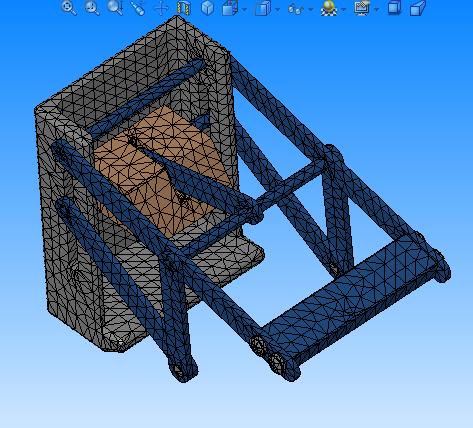
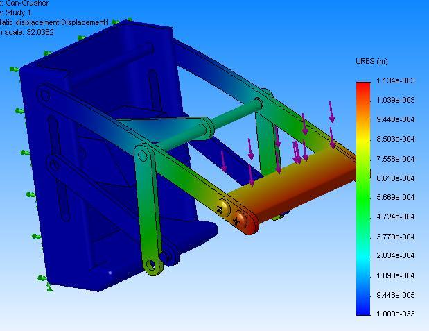
3 Basics of Finite Element Analysis (FEA) What is FEA? A complex problem is divided into a smaller and simpler problems that can be solved by using the existing knowledge of mechanics of materials and mathematical tools Why FEA? Modern mechanical design involves complicated shapes, sometimes made of different materials that as a whole cannot be solved by existing mathematical tools. Engineers need the FEA to evaluate their designs Ken Youssefi Introduction Mechanical to Engineering, Dept E

4 Basics of Finite Element Analysis The process of dividing the model into small pieces is called meshing. The behavior of each element is well-known under all possible support and load scenarios. The finite element method uses elements with different shapes. Elements share common points called nodes. mesh analysis results Ken Youssefi Introduction Mechanical to Engineering, Dept E

5 5
6 Computer Numerical Control (CNC) A CNC machine is an NC machine with the added feature of an on-board computer. 1 A solid model of the part is created. 2 The program path is generated by computer 6


7 CNC Machines Machining Centers, equipped with automatic tool changers, are capable of changing 90 or more tools. Can perform milling, drilling, tapping, boring on many faces. 7
8 Creating Solid Models Parametric Modeling Concept Parametric is a term used to describe a dimension s ability to change the shape of model geometry if the dimension value is modified. Feature-based is a term used to describe the various components of a model. A part can consist of various types of features such as holes, grooves, fillets, and chamfers. Parametric models are featured-based, parametric, solid modeling design program: SolidWorks, Pro-Engineer, Unigraphics (CSG and parametric), Autodesk Inventor,.. 8
9 Design Intent In parametric modeling, dimensions control the model. Design intent is how your model will react when dimension values are changed. 9
10 Design Intent The drawing shows the intent of the designer that the inclined plane (chamfer) should have a flat area measuring 2.5 inches and that it should start at a point 1.25 inches from the base of the drawing. These parameters are what the designer deemed significant for this model Remember that the placement of dimensions is very important because they are being used to drive the shape of the geometry. If the 2.5 in. vertical dimension increases, the 2.5 in. flat across the chamfer will be maintained, but its angle will change. 10
11 Design Intent In this drawing, what is important to the designer is the vertical location and horizontal dimension of the chamfer, rather than the flat of the chamfer In the last drawing, the designer calls for a specific angle for the chamfer. In this case the angle of the chamfer should be dimensioned O 11
12 Design Intent 12

13 Parametric Modeling The true power of parametric modeling shines through when design changes need to be made. The design modification is made by simply changing a dimension. Pattern: 8 Holes Since the counterbore is associated with the top surface of the ring, any changes in the thickness of the ring would automatically be reflected on the counterbore depth. 13
14 Sketching and Features When discussing the mind-set needed for working with parametric modelers, two topics need to be expanded: Sketching and Features Sketching Take the word sketch literally. A sketch should be just that, a sketch. When sketching it is not necessary to create geometry with accuracy. Lines, arcs, and additional geometry need not be created with exact dimensions in mind. When the dimensions are added, the sketch will change size and shape. This is the essence of Parametric Modeling. In short, the sketch need only be the approximate size and shape of the part being designed. When dimensions are added, they will drive the size and the shape of the geometry. 14


15 Features Sketched Feature Sketching and Features Create a 2D sketch. Create a feature from the sketch by extruding, revolving, sweeping, lofting and blending Revolved feature Extruded feature 15
16 Creating Solids - Sweep A Sweep feature requires a profile and a path. The profile will follow the path to create the solid. Profile (section) Path (guide) Sweep feature 16


17 Creating Solids Loft (different profiles) Round profile Round profile Square profile Sections (profiles) do not have to be sketched on parallel planes All sections must be either closed or open 17
18 Creating Features from Sketches Loft in SolidWorks 18


19 Applied Feature Applied feature does not require a sketch. It is applied directly to the model. Fillets and chamfers are very common applied features. Chamfer Fillet 19


20 Shell hollowing out a solid Applied Features 20
 pattern")
21 Applied Features - Patterns Linear (rectangular) pattern 21
 pattern 1.")

22 Applied Features - Patterns Linear (rectangular) pattern 1. Select direction 1 and 2 2. Select spacing in dir. 1 and 2 3. Select # of features in dir. 1 and 2 4. Select feature to pattern 22

23 Applied Features - Patterns Circular (polar) pattern 1. Select axis of rotation 3. Select # of features 2. Select spacing between features 4. Select feature to pattern 23
Introduction to Solid Modeling Parametric Modeling. Mechanical Engineering Dept.
 Introduction to Solid Modeling Parametric Modeling 1 Why draw 3D Models? 3D models are easier to interpret. Simulation under real-life conditions. Less expensive than building a physical model. 3D models
Feature-Based Modeling and Optional Advanced Modeling. ENGR 1182 SolidWorks 05
 Feature-Based Modeling and Optional Advanced Modeling ENGR 1182 SolidWorks 05 Today s Objectives Feature-Based Modeling (comprised of 2 sections as shown below) 1. Breaking it down into features Creating
Autodesk Inventor 6 Essentials Instructor Guide Chapter Four: Creating Placed Features Chapter Outline This chapter provides instruction on the follow
 Chapter Four: Creating Placed Features Chapter Outline This chapter provides instruction on the following topics and provides exercises for students to practice their skills. Day Two Topic: How to create
Technical Education Services
 Autodesk Fusion 360: Introduction to Parametric Modeling Course Length: 3 days Official Training Guide The Autodesk Fusion 360 Introduction to Parametric Modeling training course provides you with an understanding
3. Preprocessing of ABAQUS/CAE
 3.1 Create new model database 3. Preprocessing of ABAQUS/CAE A finite element analysis in ABAQUS/CAE starts from create new model database in the toolbar. Then save it with a name user defined. To build
SOLIDWORKS 2016 and Engineering Graphics
 SOLIDWORKS 2016 and Engineering Graphics An Integrated Approach Randy H. Shih SDC PUBLICATIONS Better Textbooks. Lower Prices. www.sdcpublications.com Powered by TCPDF (www.tcpdf.org) Visit the following
SolidWorks 2013 and Engineering Graphics
 SolidWorks 2013 and Engineering Graphics An Integrated Approach Randy H. Shih SDC PUBLICATIONS Schroff Development Corporation Better Textbooks. Lower Prices. www.sdcpublications.com Visit the following
3D Design with 123D Design
 3D Design with 123D Design Introduction: 3D Design involves thinking and creating in 3 dimensions. x, y and z axis Working with 123D Design 123D Design is a 3D design software package from Autodesk. A
SOLIDWORKS: Lesson III Patterns & Mirrors. UCF Engineering
 SOLIDWORKS: Lesson III Patterns & Mirrors UCF Engineering Solidworks Review Last lesson we discussed several more features that can be added to models in order to increase their complexity. We are now
Creo for Analyst. Overview
 Creo for Analyst Overview In this course, you will learn how to utilize the core functionality enhancements in Creo Parametric 2.0. First, you will become familiar with using and customizing the new ribbon
Autodesk Inventor 2018
 Parametric Modeling with Autodesk Inventor 2018 NEW Contains a new chapter on 3D printing Randy H. Shih SDC PUBLICATIONS Better Textbooks. Lower Prices. www.sdcpublications.com Powered by TCPDF (www.tcpdf.org)
Geometric Modeling. Creating 3D solid geometry in a computer! MAE 455 Computer-Aided Design and Drafting
 Geometric Modeling Creating 3D solid geometry in a computer! Partial History of Geometric Modeling 1963 Wireframe Computer Graphics Invented (Ivan Sutherland, MIT) 2 Partial History 1964 DAC-1, General
Geometric Modeling. Introduction
 Geometric Modeling Introduction Geometric modeling is as important to CAD as governing equilibrium equations to classical engineering fields as mechanics and thermal fluids. intelligent decision on the
Education Curriculum Surface Design Specialist
 Education Curriculum Surface Design Specialist Invest your time in imagining next generation designs. Here s what we will teach you to give shape to your imagination. CATIA Surface Design Specialist CATIA
Geometric Modeling. Creating 3D solid geometry in a computer! Partial History of Geometric Modeling
 Geometric Modeling Creating 3D solid geometry in a computer! Partial History of Geometric Modeling 1963 Wireframe Computer Graphics Invented (Ivan Sutherland, MIT) 2 1 Partial History 1964 DAC-1, General
Solid Modeling: Part 1
 Solid Modeling: Part 1 Basics of Revolving, Extruding, and Boolean Operations Revolving Exercise: Stepped Shaft Start AutoCAD and use the solid.dwt template file to create a new drawing. Create the top
Chapter 4 Feature Design Tree
 4-1 Chapter 4 Feature Design Tree Understand Feature Interactions Use the FeatureManager Design Tree Modify and Update Feature Dimensions Perform History-Based Part Modifications Change the Names of Created
Autodesk Inventor 2019 and Engineering Graphics
 Autodesk Inventor 2019 and Engineering Graphics An Integrated Approach Randy H. Shih SDC PUBLICATIONS Better Textbooks. Lower Prices. www.sdcpublications.com Powered by TCPDF (www.tcpdf.org) Visit the
Modeling a Gear Standard Tools, Surface Tools Solid Tool View, Trackball, Show-Hide Snaps Window 1-1
 Modeling a Gear This tutorial describes how to create a toothed gear. It combines using wireframe, solid, and surface modeling together to create a part. The model was created in standard units. To begin,
Complex Shapes Creation with Hybrid Modelling
 Complex Shapes Creation with Hybrid Modelling Peter De Strijker Technical Sales Executive MFG - Benelux Our Customer s Industries Discrete product manufacture Agenda Quality Analyses of sketches and surfaces
Autodesk Inventor - Basics Tutorial Exercise 1
 Autodesk Inventor - Basics Tutorial Exercise 1 Launch Inventor Professional 2015 1. Start a New part. Depending on how Inventor was installed, using this icon may get you an Inch or Metric file. To be
CNC 8055 MC EXAMPLES MANUAL REF Ref. 0601
 EXAMPLES MANUAL Ref. 0601 All rights reserved. No part of this documentation may be copied, transcribed, stored in a data backup system or translated into any language without Fagor Automation's explicit
A Comprehensive Introduction to SolidWorks 2011
 A Comprehensive Introduction to SolidWorks 2011 Godfrey Onwubolu, Ph.D. SDC PUBLICATIONS www.sdcpublications.com Schroff Development Corporation Chapter 2 Geometric Construction Tools Objectives: When
Autodesk Inventor 2016
 Parametric Modeling with Autodesk Inventor 2016 Randy H. Shih SDC PUBLICATIONS Better Textbooks. Lower Prices. www.sdcpublications.com Powered by TCPDF (www.tcpdf.org) Visit the following websites to learn
2D CAD. Courseware Issued: DURATION: 64 hrs
 2D CAD Introduction File management Orthographic drawings View management Display management Layer management Selection methods Parametric drawings Symbol creation using block BOM / Joinery details creation
EML 2322L -- MAE Design and Manufacturing Laboratory. CNC Machining
 EML 2322L -- MAE Design and Manufacturing Laboratory CNC Machining Intro to CNC Machining CNC stands for computer numeric controlled. It refers to any machine tool (i.e. mill, lathe, drill press, etc.)
6. CAD SOFTWARE. CAD is a really useful tool for every engineer, and especially for all the designers.
 6. CAD SOFTWARE CAD is a really useful tool for every engineer, and especially for all the designers. Not only because it makes drawing easier, but because it presents the advantage that if any detail
ECE 480: Design Team #9 Application Note Designing Box with AutoCAD
 ECE 480: Design Team #9 Application Note Designing Box with AutoCAD By: Radhika Somayya Due Date: Friday, March 28, 2014 1 S o m a y y a Table of Contents Executive Summary... 3 Keywords... 3 Introduction...
Autodesk 123D Beta5 Overview
 Autodesk 123D Beta5 Overview Welcome. This overview document for Autodesk 123D will assist you in developing your understanding of the software and how you can use it to create your design ideas. Designing
Feature-based CAM software for mills, multi-tasking lathes and wire EDM. Getting Started
 Feature-based CAM software for mills, multi-tasking lathes and wire EDM www.featurecam.com Getting Started FeatureCAM 2015 R3 Getting Started FeatureCAM Copyright 1995-2015 Delcam Ltd. All rights reserved.
Freeform / Freeform PLUS
 Freeform / Freeform PLUS WORKING WITH FREEFORM Work from Coarse Clay to Fine When creating new models from scratch, it is best to first create a rough shape using a coarse clay setting such as Rough Shape
Parametric Modeling Design and Modeling 2011 Project Lead The Way, Inc.
 Parametric Modeling Design and Modeling 2011 Project Lead The Way, Inc. 3D Modeling Steps - Sketch Step 1 Sketch Geometry Sketch Geometry Line Sketch Tool 3D Modeling Steps - Constrain Step 1 Sketch Geometry
ME Week 3 Project 3 - Plastic Part Thicken Method
 Plastic Part Commands The following section will give a further overview of the Autodesk Inventor plastic part commands. 1. Project 3 This project will further introduce you to the Autodesk Inventor 2012
SOLIDWORKS Parametric Modeling with SDC. Covers material found on the CSWA exam. Randy H. Shih Paul J. Schilling
 Parametric Modeling with SOLIDWORKS 2015 Covers material found on the CSWA exam Randy H. Shih Paul J. Schilling SDC PUBLICATIONS Better Textbooks. Lower Prices. www.sdcpublications.com Powered by TCPDF
Parametric Modeling. With. Autodesk Inventor. Randy H. Shih. Oregon Institute of Technology SDC PUBLICATIONS
 Parametric Modeling With Autodesk Inventor R10 Randy H. Shih Oregon Institute of Technology SDC PUBLICATIONS Schroff Development Corporation www.schroff.com www.schroff-europe.com 2-1 Chapter 2 Parametric
Structural & Thermal Analysis Using the ANSYS Workbench Release 12.1 Environment
 ANSYS Workbench Tutorial Structural & Thermal Analysis Using the ANSYS Workbench Release 12.1 Environment Kent L. Lawrence Mechanical and Aerospace Engineering University of Texas at Arlington SDC PUBLICATIONS
SOLIDWORKS 2016: A Power Guide for Beginners and Intermediate Users
 SOLIDWORKS 2016: A Power Guide for Beginners and Intermediate Users The premium provider of learning products and solutions www.cadartifex.com Table of Contents Dedication... 3 Preface... 15 Part 1. Introducing
Autodesk Fusion 360: Model. Overview. Modeling techniques in Fusion 360
 Overview Modeling techniques in Fusion 360 Modeling in Fusion 360 is quite a different experience from how you would model in conventional history-based CAD software. Some users have expressed that it
Module 1: Basics of Solids Modeling with SolidWorks
 Module 1: Basics of Solids Modeling with SolidWorks Introduction SolidWorks is the state of the art in computer-aided design (CAD). SolidWorks represents an object in a virtual environment just as it exists
Inventor 201. Work Planes, Features & Constraints: Advanced part features and constraints
 Work Planes, Features & Constraints: 1. Select the Work Plane feature tool, move the cursor to the rim of the base so that inside and outside edges are highlighted and click once on the bottom rim of the
Course Modules for CATIA V6 2013x Essentials for New Users Training Online:
 Course Modules for CATIA V6 2013x - 100 Essentials for New Users Training Online: 1 Launching CATIA V6 The PLM Story Import IGI Models (Essentials) Launching CATIA V6 Choosing a Security Context 2 V6 Navigation
Parametric Modeling with SolidWorks
 Parametric Modeling with SolidWorks 2012 LEGO MINDSTORMS NXT Assembly Project Included Randy H. Shih Paul J. Schilling SDC PUBLICATIONS Schroff Development Corporation Better Textbooks. Lower Prices. www.sdcpublications.com
3D Modeling and Design Glossary - Beginner
 3D Modeling and Design Glossary - Beginner Align: to place or arrange (things) in a straight line. To use the Align tool, select at least two objects by Shift left-clicking on them or by dragging a box
Parametric Modeling with SOLIDWORKS 2017
 Parametric Modeling with SOLIDWORKS 2017 NEW Contains a new chapter on 3D printing Covers material found on the CSWA exam Randy H. Shih Paul J. Schilling SDC PUBLICATIONS Better Textbooks. Lower Prices.
SOLIDWORKS Simulation
 SOLIDWORKS Simulation Length: 3 days Prerequisite: SOLIDWORKS Essentials Description: SOLIDWORKS Simulation is designed to make SOLIDWORKS users more productive with the SOLIDWORKS Simulation Bundle. This
CATIA V5 Parametric Surface Modeling
 CATIA V5 Parametric Surface Modeling Version 5 Release 16 A- 1 Toolbars in A B A. Wireframe: Create 3D curves / lines/ points/ plane B. Surfaces: Create surfaces C. Operations: Join surfaces, Split & Trim
Autodesk Inventor : From Concept to Digital Prototype
 Autodesk Inventor : From Concept to Digital Prototype Bryan Fields Advanced Solutions, Inc. MA305-5 Using the tools available in Autodesk Inventor, this session will look at the progression from concept
Quarter Symmetry Tank Stress (Draft 4 Oct 24 06)
") Quarter Symmetry Tank Stress (Draft 4 Oct 24 06) Introduction You need to carry out the stress analysis of an outdoor water tank. Since it has quarter symmetry you start by building only one-fourth of
Quarter Symmetry Tank Stress (Draft 4 Oct 24 06) Introduction You need to carry out the stress analysis of an outdoor water tank. Since it has quarter symmetry you start by building only one-fourth of
3D Modeling. Visualization Chapter 4. Exercises
 Three-dimensional (3D) modeling software is becoming more prevalent in the world of engineering design, thanks to faster computers and better software. Two-dimensional (2D) multiview drawings made using
Polar coordinate interpolation function G12.1
 Polar coordinate interpolation function G12.1 On a Turning Center that is equipped with a rotary axis (C-axis), interpolation between the linear axis X and the rotary axis C is possible by use of the G12.1-function.
The following learning resources are pre-requisites to help prepare you in supporting your students through this course.
 Introduction to CAD: From 2D to 3D Modeling Instructor Guide This instructor guide is a comprehensive tool for facilitating this course in the classroom. Prepare to teach this course by thoroughly reviewing
Autodesk Inventor Design Exercise 2: F1 Team Challenge Car Developed by Tim Varner Synergis Technologies
 Autodesk Inventor Design Exercise 2: F1 Team Challenge Car Developed by Tim Varner Synergis Technologies Tim Varner - 2004 The Inventor User Interface Command Panel Lists the commands that are currently
FAGOR AUTOMATION MC TRAINING MANUAL
 FAGOR AUTOMATION MC TRAINING MANUAL ACER MC TRAINING MANUAL 8 holes 1/2" depth grid pattern R0.125 1.5 6 unit: inch R0.25 4 1.25 2 2.675 1/2" depth rectangular pocket 1/2" depth circular pocket R0.75 8
SolidWorks FeatureWorks: Automatic versus Interactive Recognition
 SolidWorks FeatureWorks: Automatic versus Interactive Recognition What is FeatureWorks? FeatureWorks is an integrated geometry recognition module that allows for files imported to SolidWorks from other
An Overview of Computer Aided Design and Finite Element Analysis
 An Overview of Computer Aided Design and Finite Element Analysis by James Doane, PhD, PE Contents 1.0 Course Overview... 4 2.0 General Concepts... 4 2.1 What is Computer Aided Design... 4 2.1.1 2D verses
Solid Bodies and Disjointed bodies
 Solid Bodies and Disjointed bodies Generally speaking when modelling in Solid Works each Part file will contain single solid object. As you are modelling, each feature is merged or joined to the previous
PARAMETRIC MODELING FOR MECHANICAL COMPONENTS 1
 PARAMETRIC MODELING FOR MECHANICAL COMPONENTS 1 Wawre S.S. Abstract: parametric modeling is a technique to generalize specific solid model. This generalization of the solid model is used to automate modeling
MAE 455 COMPUTER-AIDED DESIGN AND DRAFTING MIDTERM EXAM PRACTICE QUESTIONS. Name: You are allowed one sheet of notes.
 47 MAE 455 COMPUTER-AIDED DESIGN AND DRAFTING MIDTERM EXAM PRACTICE QUESTIONS Name: You are allowed one sheet of notes. 1. What constraints could be added to fully constrain the wireframe shown? Include
Parametric Modeling with UGS NX 4
 Parametric Modeling with UGS NX 4 Randy H. Shih Oregon Institute of Technology SDC PUBLICATIONS Schroff Development Corporation www.schroff.com www.schroff-europe.com 2-1 Chapter 2 Parametric Modeling
Autodesk AutoCAD In Mechanical Engineering Design Edward Locke
 Autodesk AutoCAD In Mechanical Engineering Design Edward Locke Engineering Department Santa Ana College Mechanical Engineering Drafting Essentials Working Drawings: Orthographic Projection Views (multi-view,
Manufacturing Processes with the Aid of CAD/CAM Systems AMEM 405
 AMEM 405 slide 1 Manufacturing Processes with the Aid of CAD/CAM Systems AMEM 405 Dr. Sotiris Omirou AMEM 405 slide 2 CONTENTS 1. CAD/CAM definition 2. Review of Milling Process 3. Know The CNC Machine
Exercise Guide. Published: August MecSoft Corpotation
 VisualCAD Exercise Guide Published: August 2018 MecSoft Corpotation Copyright 1998-2018 VisualCAD 2018 Exercise Guide by Mecsoft Corporation User Notes: Contents 2 Table of Contents About this Guide 4
Workshop name: CAD Strategies for 3D Printing
 Page 1 of 9 Workshop name: CAD Strategies for 3D Printing Presented by James Novak: Griffith University Lecturer, PhD Candidate, Industrial Designer Activity 1 Parametric Test Models Discussion: Additive
Extrusion Revolve. ENGR 1182 SolidWorks 02
 Extrusion Revolve ENGR 1182 SolidWorks 02 Today s Objectives Creating 3D Shapes from 2D sketches using: Extrusion Revolve SW02 In-Class Activity Extrude a Camera Revolve a Wheel SW02 Out-of-Class Homework
F1 Car. Wheel. in the Feature Manager and click Sketch on the Context toolbar, Fig. 1. (S) on the
 on the") Chapter 3 F1 Car Wheel A. Sketch Lines. Step 1. Click File Menu > New, click Part Metric and OK. Step 2. Click Front Plane in the Feature Manager and click Sketch on the Context toolbar, Fig. 1. Step 3.
Chapter 3 F1 Car Wheel A. Sketch Lines. Step 1. Click File Menu > New, click Part Metric and OK. Step 2. Click Front Plane in the Feature Manager and click Sketch on the Context toolbar, Fig. 1. Step 3.
SolidWorks 2014 Part II - Advanced Techniques
 SolidWorks 2014 Part II - Advanced Techniques Parts, Surfaces, Sheet Metal, SimulationXpress, Top-Down Assemblies, Core and Cavity Molds Paul Tran CSWE, CSWI SDC PUBLICATIONS Better Textbooks. Lower Prices.
SolidWorks 2013 Part II - Advanced Techniques
 SolidWorks 2013 Part II - Advanced Techniques Parts, Surfaces, Sheet Metal, SimulationXpress, Top-Down Assemblies, Core and Cavity Molds Paul Tran CSWE, CSWI Supplemental Files SDC PUBLICATIONS Schroff
Structural & Thermal Analysis using the ANSYS Workbench Release 11.0 Environment. Kent L. Lawrence
 ANSYS Workbench Tutorial Structural & Thermal Analysis using the ANSYS Workbench Release 11.0 Environment Kent L. Lawrence Mechanical and Aerospace Engineering University of Texas at Arlington SDC PUBLICATIONS
Week 2 Lecture 3D Part Design. ME Introduction to CAD/CAE Tools
 Week 2 Lecture 3D Part Design Lecture Topics Product Lifecycle Process Review Detailed Product Engineering Challenges and Purpose Evolution of CAD General 3D Design Concepts Case Study Examples Product
Chapter 6: Create Surfaces from Curves
 A common way of working in 3-D is to draw curves that represent edges, profiles, cross-sections, or other surface features and then to use surfacing commands to create surfaces from those curves. Edge
TRAINING GUIDE SOLIDS-LESSON-3
 TRAINING GUIDE SOLIDS-LESSON-3 Mastercam Training Guide Objectives You will generate the solid model from the existing 2-dimensional geometry. This Lesson covers the following topics: Open an existing
SOLIDWORKS 2019 Advanced Techniques
 SOLIDWORKS 2019 Advanced Techniques Mastering Parts, Surfaces, Sheet Metal, SimulationXpress, Top Down Assemblies, Core & Cavity Molds Paul Tran CSWE, CSWI SDC PUBLICATIONS Better Textbooks. Lower Prices.
Modeling a Scanned Object with RapidWorks
 Modeling a Scanned Object with RapidWorks RapidWorks allows you to use a scanned point cloud of an object from the NextEngine Desktop 3D Scanner to create a CAD representation of an object. This guide
Time and Location: T 6:30 PM to 9:20 PM SAL 127 (Section 1, 28758) Th 6:30 PM to 9:20 PM SAL 127 (Section 2, 28759)
 Th 6:30 PM to 9:20 PM SAL 127 (Section 2, 28759)") UNIVERSITY OF SOUTHERN CALIFORNIA AME 408, Computer-Aided Design of Mechanical Systems Fall 2017 Time and Location: T 6:30 PM to 9:20 PM SAL 127 (Section 1, 28758) Th 6:30 PM to 9:20 PM SAL 127 (Section
UNIVERSITY OF SOUTHERN CALIFORNIA AME 408, Computer-Aided Design of Mechanical Systems Fall 2017 Time and Location: T 6:30 PM to 9:20 PM SAL 127 (Section 1, 28758) Th 6:30 PM to 9:20 PM SAL 127 (Section
EXPERIENCE THE POWER. THE NEW BobCAD-CAM V31. We have upgraded the entire customer experience to be more intuitive, modern and efficient.
 01 EXPERIENCE THE POWER V31 Whether you re a leading manufacturer or just starting out, BobCAD-CAM has the features, training & support you need to machine better parts FASTER and EASIER, for LESS. THE
Brief Introduction to MasterCAM X4
 Brief Introduction to MasterCAM X4 Fall 2013 Meung J Kim, Ph.D., Professor Department of Mechanical Engineering College of Engineering and Engineering Technology Northern Illinois University DeKalb, IL
Curriculum Guide. Creo 4.0
 Curriculum Guide Creo 4.0 Live Classroom Curriculum Guide Update to Creo Parametric 4.0 from Creo Parametric 3.0 Introduction to Creo Parametric 4.0 Advanced Modeling using Creo Parametric 4.0 Advanced
Geometric Modeling Systems
 Geometric Modeling Systems Wireframe Modeling use lines/curves and points for 2D or 3D largely replaced by surface and solid models Surface Modeling wireframe information plus surface definitions supports
L1 - Introduction. Contents. Introduction of CAD/CAM system Components of CAD/CAM systems Basic concepts of graphics programming
 L1 - Introduction Contents Introduction of CAD/CAM system Components of CAD/CAM systems Basic concepts of graphics programming 1 Definitions Computer-Aided Design (CAD) The technology concerned with the
Doctor Walt s Solid Edge Version 19 Workbook 137
 Still using the SMART DIMENSION Tool, click on the left vertical edge of the sketch. Move the cursor to the left and click to set the text position. Type 1.5 for the value and hit the ENTER Key. Next,
Solid Bodies and Disjointed Bodies
 Solid Bodies and Disjointed Bodies Generally speaking when modelling in Solid Works each Part file will contain single solid object. As you are modelling, each feature is merged or joined to the previous
Engineering designs today are frequently
 Basic CAD Engineering designs today are frequently constructed as mathematical solid models instead of solely as 2D drawings. A solid model is one that represents a shape as a 3D object having mass properties.
Modeling 3D Objects: Part 2
 Modeling 3D Objects: Part 2 Patches, NURBS, Solids Modeling, Spatial Subdivisioning, and Implicit Functions 3D Computer Graphics by Alan Watt Third Edition, Pearson Education Limited, 2000 General Modeling
Chapter 9 3D Modeling
 Chapter 9 3D Modeling Copyright The McGraw-Hill Companies, Inc. Permission required for reproduction or display. 3D Modeling Snapshot Since Mid 1980 s become common place in industry Software Types Wireframe
CATIA Surface Design
 CATIA V5 Training Exercises CATIA Surface Design Version 5 Release 19 September 2008 EDU_CAT_EN_GS1_FX_V5R19 Table of Contents (1/2) Creating Wireframe Geometry: Recap Exercises 4 Creating Wireframe Geometry:
Introduction to MasterCAM X4,7
 Introduction to MasterCAM X4,7 Spring 2014 By Meung J. Kim, Ph.D., Professor Department of Mechanical Engineering Northern Illinois University 1 Preliminaries C-Plane: flat Construction plane that can
Chapter 10. Creating 3D Objects Delmar, Cengage Learning
 Chapter 10 Creating 3D Objects 2011 Delmar, Cengage Learning Objectives Extrude objects Revolve objects Manipulate surface shading and lighting Map artwork to 3D objects Extrude Objects Extrude & Bevel
y = 4x + 2, 0 x 1 Name: Class: Date: 1 Find the area of the region that lies under the given curve:
 Name: Class: Date: 1 Find the area of the region that lies under the given curve: y = 4x + 2, 0 x 1 Select the correct answer. The choices are rounded to the nearest thousandth. 8 Find the volume of the
Licom Systems Ltd., Training Course Notes. 3D Surface Creation
 , Training Course Notes Work Volume and Work Planes...........................1 Overview..........................................1 Work Volume....................................1 Work Plane......................................1
Propeller. Chapter 13. Airplane. A. Base for Blade. Step 1. Click File Menu > New, click Part and OK.
 Chapter 13 Airplane Propeller A. Base for Blade. Step 1. Click File Menu > New, click Part and OK. Step 2. Click Top Plane in the Feature Manager and click Sketch toolbar, Fig. 1. from the Content Step
Chapter 2 Parametric Modeling Fundamentals
 2-1 Chapter 2 Parametric Modeling Fundamentals Create Simple Extruded Solid Models Understand the Basic Parametric Modeling Procedure Create 2-D Sketches Understand the "Shape before Size" Approach Use
Nerf Blaster Redesign
 Nerf Blaster Redesign ME4041 Computer Graphics and CAD April 0, 010 Submitted By: Michael Schulman Greg Mann Table of Contents Introduction. Objectives Modeling. 4 External Components 4 Internal Components.
EXPERIMENT NO: NAME OF EXPERIMENT: -01 2D & 3D CAD modelling methodology using package AutoCAD.
 SHRI SHIVAJI EDUCATION SOCIETY, AMRAVATI S, COLLEGE OF ENGINEERING & TECHNOLOGY, AKOLA Babhulgaon (JH) N.H.No.6, Akola-444104 DEPARTMENT OF MECHANICAL ENGINEERING COMPUTER SOFTWARE APPLICATIONS -I LAB.
Geometry Definition in the ADINA User Interface (AUI) Daniel Jose Payen, Ph.D. March 7, 2016
 Daniel Jose Payen, Ph.D. March 7, 2016") Geometry Definition in the ADINA User Interface (AUI) Daniel Jose Payen, Ph.D. March 7, 2016 ADINA R&D, Inc., 2016 1 Topics Presented ADINA에서쓰이는 Geometry 종류 Simple (AUI) geometry ADINA-M geometry ADINA-M
Geometry Definition in the ADINA User Interface (AUI) Daniel Jose Payen, Ph.D. March 7, 2016 ADINA R&D, Inc., 2016 1 Topics Presented ADINA에서쓰이는 Geometry 종류 Simple (AUI) geometry ADINA-M geometry ADINA-M
ANSYS Workbench Guide
 ANSYS Workbench Guide Introduction This document serves as a step-by-step guide for conducting a Finite Element Analysis (FEA) using ANSYS Workbench. It will cover the use of the simulation package through
TUTORIAL 2. OBJECTIVE: Use SolidWorks/COSMOS to model and analyze a cattle gate bracket that is subjected to a force of 100,000 lbs.
 TUTORIAL 2 OBJECTIVE: Use SolidWorks/COSMOS to model and analyze a cattle gate bracket that is subjected to a force of 100,000 lbs. GETTING STARTED: 1. Open the SolidWorks program. 2. Open a new part file.
Revolve Vertices. Axis of revolution. Angle of revolution. Edge sense. Vertex to be revolved. Figure 2-47: Revolve Vertices operation
 Revolve Vertices The Revolve Vertices operation (edge create revolve command) creates circular arc edges or helixes by revolving existing real and/or non-real vertices about a specified axis. The command
TRAINING SESSION Q3 2016
 There are 6 main topics in this training session which is focusing on 3D Import and 2D Drawing Tips and Tricks in IRONCAD. Content 3D modeling kernels... 2 3D Import... 3 Direct Face Modeling... 5 Unfold
MSC.visualNastran Desktop FEA Exercise Workbook. Pin and Bracket Assembly: Vibration Simulation in 4D
 MSC.visualNastran Desktop FEA Exercise Workbook Pin and Bracket Assembly: Vibration Simulation in 4D WS24-2 Objectives This exercise is design to introduce vibration analysis in visualnastran Desktop.
Computer Aided Engineering Applications
 Computer Aided Engineering Applications 1A.Geometric Modeling 1.1 Geometric modelling methods 1.2 Data representation 1.3 Modeling functions 1.4 Structure of a CAD system Engi 6928 - Fall 2014 1.Geometric