Computer Aided Design. Solid models and B-REP
|
|
|
- Annabelle Manning
- 6 years ago
- Views:
Transcription
1 Solid models and B-REP 1
2 Classical modelling problem : the intersection 3 independent representations of the intersection : - a 3D NURBS curve (giving points in the global XYZ coordinate system) - a 2D NURBS curve in the parametric space of surface A (giving 2D points in the coordinate system of the parametric space of surface A) - Idem for surface B A B B Parametric space of surface B 2
3 Theoretically, these three representations are equivalent... 3 independent representations of the intersection : - a 3D NURBS curve - a 2D NURBS curve (parametric space of surface A) - a 2D NURBS curve (parametric space of surface B) A In practice, there are numerical approximations B NURBS are finite approximation spaces; therefore approximation/interpolation errors do occur. The use of floating point numbers with a finite binary representation of the mantissa lead to numerical errors There is no robust way to ensure, in a geometrical sense, that a curve located on surface A is the same as the corresponding curve on surface B, i.e. that both surfaces are neighbours, and share the same edge. 3
4 Definition of a topology : non geometric relations between entities. This allows to unify the calculations (of points, normals, etc...) on entities shared (or bounding) other entities (eg. an edge shared by surfaces). It also allows the explicit definition of volumes from the surfaces that bound the volume. It may also solve the problem of orientation of surfaces 4
5 Topology S2 P4 B-REP model C4 P3 C3 S1 C2 P2 C1 P1 5
 6")
6 B-Rep model «Boundary representation» Model based on the representation of surfaces Model of exchange (STEP format) and definition The natural set of operators is richer than for CSG Extrusion, chamfer etc... Does not carry the history of construction of the model (whereas CSG usually does) 6
7 B-Rep model Consists of two types of information : Geometric Geometric information is used for defining the spatial position, the curvatures, etc... That's what we have seen until now NURBS curves and surfaces! Topological This allows to make links between geometrical entities. Two types of entities Geometric entities: (volume), surface, curve, point Topological entities : solid, face, edge, vertex A topological entity lies on a geometric entity, which is its geometrical support (when existing) 7
8 B-Rep model Complete hierarchical model 1:n Solid «shells» 1:n Boundary Face 1:n Boundary edge 1:1 if manifold, 2 otherwise } face 1:n «loops» Allow to orient faces or volumes 1:2 if manifold, n otherwise } edge «Composed of» «is related to» vertex 1:2 Boundary vertex 1:n If it exists, the geometric support (G.S.) is expressed in cartesian coordinates x,y,z G.S. expressed in parametric coordinates u,v or t 8

9 9


10 vertex 1. Coordinates x,y,z Face 1. the geometric support is surface 1, which is a surface of revolution around the axis (Oz). Edge 1. the geometric support is the curve_xyz 2. In the parametric space of the surface 1, corresponds to two boundary edges : 1 et 11 Definition of the edge 1 in the parametric space of the curve 1 Boundary vertex 1 Point_t t1 Boundary vertex 2 Point_t t2 vertex 2. Point xyz Boundary edge 1. the geometric support is a straight line (curve_uv 1) in the parametric space of the surface 1 loops Boundary edge 11. the geometric support is another straight line in the parametric space of the surface 1 Definition of the face 1 in the parametric space of the surface 1 Boundary edge corresponding to a degenerated edge (zero length and identical points of departure and arrival: vertex 2) 10
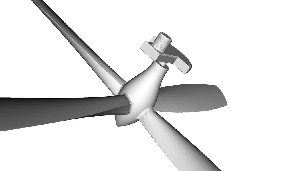
11 Solid 1: shell 1 G.S. : Nil shell 1 : Boundary face 1 Boundary face 2 Boundary face 76 Boundary face 1 : Face 1 G.S. : Nil Face 1 : Loop 1 Loop 2 Loop 3 Loop 4 G.S. : Surface_xyz 1 Excerpt of the B-REP topology of the propeller Loop 1 : Boundary edge 1... Boundary edge 12 Loop 2 : Boundary edge 13 Boundary edge 14 Boundary edge 15 Boundary edge 16 Loop 3 (4) : Boundary edge 17 (21)... Boundary edge 20 (24) Boundary edge 1 Edge 1 G.S. : Curve_uv 1 Edge 1 Boundary vertex 1 Boundary vertex 2 G.S. : Curve_xyz 2 Boundary vertex 1 Vertex 1 G.S. : Point_t 1 Vertex 1 G.S. : Point_xyz 2 11
12 Links between the B-REP topology and the actual geometry of the propeller Boundary edge 1 Edge 1 G.S. : Curve_uv 1 Curve_uv 1 : Straight line application (t) (u,v) Curve_xyz 2 : NURBS Curve application (t) (x,y,z) Face 1 : Loop 1 Loop 2 Loop 3 Loop 4 G.S. : Surface_xyz 1 Edge 1 Boundary vertex 1 Boundary vertex 2 G.S. : Curve_xyz 2 Boundary vertex 1 vertex 1 G.S. : Point_t 1 Point_t 1 t = t1 Vertex 1 G.S. : Point_xyz 2 Surface_xyz 1 : Surface of revolution NURBS Surface application (u,v) (x,y,z) Point_xyz 2 x=x1, y=y1, z=z1 12
13 How to obtain the (x,y,z) coordinates of the encircled point? 1 Use the 3D vertex directly (Point_xyz xxx) 2 Use the boundary vertices for every 3D edge (there are 3 such edges ) (Point_t t1,t2,t3) Then use those (t) to get (x,y,z) by the 3D edges 3 Use the boundary vertices of the 2D boundary edges in the face (there are 2 faces, so 4 of them), (Point_t t'1,t'2,t'3,t'4). Then use those (t) to obtain coordinates (u,v) in the parametric space of the face, thanks to 2D curves, finally, use those (u,v) to obtain (x,y,z) thanks to the geometry of the face. So there exists 8 different ways. Nothing indicates that the 8 set of 3D coordinates are exactly equal (there are numerical approximations). Only topology allows us to say that those 8 points are all referring to the same point at least conceptually. 13
14 B-Rep model Euler characteristic for polyhedra χ (S )=v e+ f Euler Poincaré formula S =v e f r=2 s h with v = number of vertices f = " of faces e = " of edges s = " of solids (independent volumes) h = " of holes going through (topol. gender) r = " of internal loops (ring) 14
15 Euler's formula Euler characteristic Example : Cube v e+f=k Opened and flattened Cube v e + f = k -1 Step 0 : we take a face off the polyhedron and flatten it to obtain a plane graph
16 Euler's formula v e+f=k e, +1f +5e, +5f v e+f=k - 1 v e+f=k - 1 Step 1 : Repeat the following operation : For each non triangular face, add one edge linking non related vertices. Each tome, the number of edges and faces is increased by 1. This is repeated until no non triangular faces remain.
17 Euler's formula v e+f=k - 1 1e, 1f 2e, 1f, 1v v e+f=k - 1 v e+f=k - 1 Step 2 : One alternates betwee these two operations - Preferentially, delete triangles that have 2 boundary edges. Every time; e decreases by 2 and f and v by 1. - Then, delete triangles with only one boundary edege. Each tile, e and f decrease by 1. This until only one triangle remain.
18 Euler's formula v e+f=k - 1
19 Euler's formula Every polygon can be decomposed into triangles Therefore, by applying the three operations described in the previous slides, we can transform the planar graph into a triangle without changing Euler's characteristic. The triangle satisfies obviously v e+f=k - 1 with k-1 = 1 Therefore, the planar graph verifies the formula. So the initial polyhedron satisfies : v e+f=k=2
20 Necessity to take rings into account - inside faces polyhedron χ (S )=2 S =v e f S =8 12 6=2 polyhedron Polyhedron with rings S = =2 S = OK Not OK! Contribution of the ring S =v e f r=220
21 Necessity to take holes into account Not an edge! polyhedron χ (S )=2 S =v e f S =8 12 6=2 Warped polyhedron S =8 12 6=2 OK Polyhedron with one hole, 4 edges less, 2 faces less, 4 vertices less χ (S )= Not OK! Contribution of the hole χ (S )=v e+ f r +2 h=2 21
22 Every B-rep model is identifiable (topologically) to a «point» in a 6-dimensional vector space. Vector space of coordinates v, e, f, s, h, r. Any topologically valid model shall verify the EulerPoincaré relation This relation defines an «hyperplane» ( of dimension 5) in a 6-dimensional space The equation of this hyperplane is : v e f 2 s 2 h r=0 22
23 v e f 2 s 2 h r=0 We can update a valid solid and modify the 6 numbers characterising a model with a transformation that yields a valid solid for which : v v e e f f 2 s 2 s 2 h 2 h r r=0 v e f 2 s 2 h r=0 In this way, add a vertex ( v=1) must be accompanied, one way or another, by addition of an edge ( e=1) OR of the withdrawal of a face ( f = 1), etc... Elementary operations satisfying the Euler-Poincaré relation are called Euler operators. They allow staying on the «hyperplane» of validity while changing the topological configuration 23
24 Euler operators The use of Euler operators guarantees the topological validity of the result Here we don't check the geometric validity (selfintersections etc...) We identify them under the form : MaKb where M = Make K = Kill and a and b are a sequence of entities : vertex, edge, face, solid, hole or ring. In total, there are 99 Euler operators aiming to modify the number of entities by at most one unit. These are divided in inverses, plus the identity operator. Among those 49 operators, we can chose 5 linearly independent operators (the hyperplane has 5 dimensions) Those 5 independent operators form a base for the hyperplane of topologically admissible models 24
25 Example of a set of Euler operators inverses MEV, Make an Edge and a Vertex MEF, Make an Edge and a Face MEKR, Make an Edge and Kill a Ring MVFS, Make a Vextex, a Face and a Shell KFMRH, Kill a Face Make a Ring and a Hole KEV, Kill an Edge and a Vertex KEF, Kill an Edge and a Face KEMR, Kill an Edge and Make a Ring KVFS, Kill a Vertex, a Face and a Shell MFKRH, Make a Face, Kill a Ring and a Hole Proof by Mäntylä (1984) that those operators allow to build every valid solid (since they are independent) Those operators form a base of the space of valid configurations (the «hyperplane») 25
26 There are three types of operators in this set : Skeleton operators MVFS and KVFS Local operators MEV, KEV, MEF, KEF, KEMR, MEKR Allow to modify connectivities for existing volumes Don't modify fundamental topological characteristics of the surfaces - nb of handles/ holes (topological gender) and number of independent volumes Global operators KFMRH and MFKRH Allow to build/destroy elementary volumes Allow to add / remove handles (change the topological gender) Only the skeleton and global operators do change the topological gender. 26
27 Euler operators «Skeleton» operators MVFS; KVFS Allow to «build» an «elementary» volume from void (which is an admissible topological structure) or destroy it. MVFS Nihil KVFS v=0 e=0 f =0 h=0 r=0 s=0 v=1 e=0 f =1 h=0 r=0 s=1 Only one face - its boundary is reduced to a single vertex 27
28 Euler operators Local operators MEV, KEV (case 1) MEV KEV v e f h r s v 1 e 1 f h r s 28
29 Euler operators Local operators MEV, KEV (case 2) MEV KEV v e f h r s v 1 e 1 f h r s 29
30 Euler operators Local operators MEV, KEV (case 3) MEV KEV v=1 e=0 f =1 h=0 r=0 s=1 v=2 e=1 f =1 h=0 r=0 s=1 30
31 Euler operators Local operators MEF, KEF (case 1) MEF KEF v e f h r s v e 1 f 1 h r s 31
")

32 Euler operators Local operators MEF, KEF (case 2) MEF KEF v=1 e=0 f =1 h=0 r=0 s=1 v=1 e=1 f =2 h=0 r=0 s=1 32
33 Euler operators Local operators MEF, KEF (case 3) MEF KEF v e f h r s v e 1 f 1 h r s 33
34 Euler operators Local operators KEMR, MEKR (case 1) KEMR MEKR v e f h r s v e 1 f h r 1 s 34
35 Euler operators Local operators KEMR, MEKR (case 2 : the loop for the internal ring is reduced to a single vertex ) KEMR MEKR v e f h r s v e 1 f h r 1 s 35
 KEMR MEKR v=2 e=1 f =1 h=0 r=0 s=1 v=2 e=0 f =1 h=0 r=1 s=1 36")
36 Euler operators Local operators KEMR, MEKR (case 3 : both loops are reduced to one vertex one is the ring; the other is the external loop of the face) KEMR MEKR v=2 e=1 f =1 h=0 r=0 s=1 v=2 e=0 f =1 h=0 r=1 s=1 36
37 Euler operators Global operators KFMRH, MFKRH (case 1 : allow the creation / destruction of holes in a solid) KFMRH v=16 e=24 f =11 h=0 r=1 s=1 MFKRH v=16 e=24 f =10 h=1 r=2 s=137
38 Euler operators Global operators KFMRH, MFKRH (case 2) : join two independent solids : here more judiciously called Kill Face, Solid and Make Ring (KFSMR) Interpretation of global operators is sometimes confusing KFMRH (KFSMR) v=16 e=24 f =12 h=0 r=0 s=2 MFKRH (MFSKR) v=16 e=24 f =11 h=0 r=1 s=1 38


39 Example of use of Euler operators MVFS v=1 e=0 f =1 h=0 r=0 s=1 MEV v=2 e=1 f =1 h=0 r=0 s=1 2 x MEV v=4 e=3 f =1 h=0 r=0 s=1 MEF v=4 e=4 f =2 h=0 r=0 s=1 39


40 Example of use of Euler operators 4 x MEV v=4 e=4 f =2 h=0 r=0 s=1 v=8 e=8 f =2 h=0 r=0 s=1 MEF v=8 e=9 f =3 h=0 r=0 s=1 3 x MEF v=8 e=12 f =6 h=0 r=0 s=1 40


41 Example of use of Euler operators S. Havemann 41
42 Those operators have a vectorial form in the basis of elementary entities v e f h r s ( 1, 1, 0, 0, 0, 0) MEV, Make an Edge and a Vertex ( 0, 1, 1, 0, 0, 0) MEF, Make a Face and an Edge ( 0,-1, 0, 0, 1, 0) KEMR, Kill an Edge Make a Ring ( 1, 0, 1, 0, 0, 1) MVFS, Make a Vertex, a Face and a Solid ( 0, 0,-1, 1, 1, 0) KFMRH, Kill a Face, Make a Ring and a Hole In order to have a complete basis of the configuration space, a vector orthogonal to the hyperplane of acceptable configurations must be added v e f 2 s 2 h r=0 The coefficients of the equation of hyperplane are precisely the coordinates of the orthogonal vector... v e f h r s ( 1,-1, 1, 2,-1,-2) Euler-Poincaré 42
43 Any transformation can thus be expressed easily using matrix operations A is a basis of the topological configurations space The columns of A are the variation of the number of entities for each operator, and the E-P relation A= ( Columns corresponding to each of the Euler operators Column corresponding to EulerPoincaré's relation ) q=a p Vector representing the number of times that each operator is applied Vector representing the number (or the variation of the number) of elementary entities 43
44 A is composed of linearly independent vectors, thus one can get the inverse... q=a p A 1 q=a 1 A p 1 p=a q Vector representing the number of times each operator is applied They are the Euler Coordinates A = Vector representing the number of elementary entities ( ) A Vector that is orthogonal to the «hyperplane»... 44
45 Determination of elementary operations... v=16 e=24 q= f =11 = 16,24,11,0,1,1 h=0 r=1 s=1 p=a 1 q p=(15,10,1,1,0,0) 15 x MEV, Make an Edge and a Vertex 10 x MEF, Make a Face and an Edge 1 x MVFS, Make a Vertex, a Face and a Solid 1 x KEMR, Kill an Edge Make a Ring 0 x KFMRH, Kill a Face, Make a Ring and a Hole T The vector q respects the Euler-Poincaré relation 45
46 Are Euler coordinates sufficient to define the topology of a solid? No. 1 x MEF, Make an Edge and a Face 1 x KEF, Kill an Edge and a Face 7 x MEV, Make an Edge and a Vertex 7 x MEF, Make an Edge and a Face 1 x MVFS, Make a Vertex, a Face and a Solid 0 x KEMR, Kill an Edge Make a Ring 0 x KFMRH, Kill a Face, Make a Ring and a Hole Identical Euler coordinates 7 x MEV 7 x MEF 1 x MVFS 0 x KEMR 0 x KFMRH 46
47 Each Euler operator takes a certain number of parameters, in principle the entities to destroy/ or replace, and data necessary to creation of new entities. These depend on the structure of data used to represent the B-Rep object Application of an Euler operator is not always possible, the entities involved must exist and respect some conditions KEF for example may only be applied on an edge separating two distinct faces... if not, one does not remove any face from the model! 47
48 Conditions of application of Euler operators MEV, Make an Edge and a Vertex Empty space KEV, Kill an Edge and a Vertex The edge has two distinct vertices MEF, Make an Edge and an Face Vertices belonging to the same boundary loop of one face KEF, Kill an Edge and a Face Distinct faces located on both sides of the edge MEKR, Make an Edge and Kill a Ring Vertices belong to distinct boundary loops of the same face KEMR, Kill an Edge and Make a Ring Same face located on both sides of the edge, which is not part of a ring MVFS, Make a Vextex, a Face and a Shell Empty space KVFS, Kill a Vertex, a Face and a Shell The shell (solid) has no edges and has only one vertex (elementary volume) KFMRH, Kill Face Make a Ring and a Hole The face cannot hold any ring MFKRH, Make a Face, Kill a Ring and a Hole May be only applied to a ring 48
49 Some examples of the application of Euler operators (not shown here) Extrusion of a face Junction of two solids Cutting out a solid by a plane Boolean operations between solids 49
50 The most used data structure in a manifold B-Rep representation : Half-Edge data structure HalfEdge he1 Face A he1 he2 e e HalfEdge he2 Face B Edge e 50
51 Basic entities shell contains : Solid number Reference to face, edge, vertex of solid face contains : Face number Ref. to an external loop Ref. to a list of internal loop Ref. to shell Ref. to surface nurbs or other (the geometric support) 51
52 loop contains : edge contains : Ref. to a list of halfedge Ref. to face Ref. to halfedge of straight line Ref. To the left halfedge Ref. to a curve nurbs or other (the geometric support) halfedge contains : Ref. to the parent edge Ref. to the starting vertex Ref. to the holding loop 52
53 vertex contains : Vertex number Reference to one of the halfedges Coordinates (the geometric support) A simplified implementation (without geometry other than vertices coordinates) in C++ of a B-rep modeller based on these ideas is available: 53


54 B-Rep model Possibility of automatic topological operations Here, elimination of small features in order to generate a mesh for numerical simulation in mechanical engineering. 54 V François
55 Bibliographic note M. Mäntylä, An Introduction to Solid Modelling, Computer Science Press, 1988 I. Stroud, Solid Modelling and CAD Systems : How to Survive a CAD System, Springer, 2011(available on-line from the university campus) 55
The Principle of Duality in Data Structures and Euler Operators of Solid Modelers
 The 3rd International Conference on Design Engineering and Science, ICDES 2014 Pilsen, Czech Republic, August 31 September 3, 2014 The Principle of Duality in Data Structures and Euler Operators of Solid
Introduction to Solid Modeling
 Introduction to Solid Modeling Hongxin Zhang and Jieqing Feng 2007-01-15 State Key Lab of CAD&CG Zhejiang University Contents Solid Representations: An Introduction Wireframe Models Boundary Representations
Chapter 12 Solid Modeling. Disadvantages of wireframe representations
 Chapter 12 Solid Modeling Wireframe, surface, solid modeling Solid modeling gives a complete and unambiguous definition of an object, describing not only the shape of the boundaries but also the object
Geometric Modeling. Introduction
 Geometric Modeling Introduction Geometric modeling is as important to CAD as governing equilibrium equations to classical engineering fields as mechanics and thermal fluids. intelligent decision on the
Computer Aided Engineering Applications
 Computer Aided Engineering Applications 1A.Geometric Modeling 1.1 Geometric modelling methods 1.2 Data representation 1.3 Modeling functions 1.4 Structure of a CAD system Engi 6928 - Fall 2014 1.Geometric
Solid Modeling Lecture Series. Prof. Gary Wang Department of Mechanical and Manufacturing Engineering The University of Manitoba
 Solid Modeling 25.353 Lecture Series Prof. Gary Wang Department of Mechanical and Manufacturing Engineering The University of Manitoba Information complete, unambiguous, accurate solid model Solid Modeling
Solid Modelling. Graphics Systems / Computer Graphics and Interfaces COLLEGE OF ENGINEERING UNIVERSITY OF PORTO
 Solid Modelling Graphics Systems / Computer Graphics and Interfaces 1 Solid Modelling In 2D, one set 2D line segments or curves does not necessarily form a closed area. In 3D, a collection of surfaces
Geometric Modeling Mortenson Chapter 11. Complex Model Construction
 Geometric Modeling 91.580.201 Mortenson Chapter 11 Complex Model Construction Topics Topology of Models Connectivity and other intrinsic properties Graph-Based Models Emphasize topological structure Boolean
Chapter 4 Concepts from Geometry
 Chapter 4 Concepts from Geometry An Introduction to Optimization Spring, 2014 Wei-Ta Chu 1 Line Segments The line segment between two points and in R n is the set of points on the straight line joining
CS3621 Midterm Solution (Fall 2005) 150 points
 150 points") CS362 Midterm Solution Fall 25. Geometric Transformation CS362 Midterm Solution (Fall 25) 5 points (a) [5 points] Find the 2D transformation matrix for the reflection about the y-axis transformation (i.e.,
CS362 Midterm Solution Fall 25. Geometric Transformation CS362 Midterm Solution (Fall 25) 5 points (a) [5 points] Find the 2D transformation matrix for the reflection about the y-axis transformation (i.e.,
Physically-Based Modeling and Animation. University of Missouri at Columbia
 Overview of Geometric Modeling Overview 3D Shape Primitives: Points Vertices. Curves Lines, polylines, curves. Surfaces Triangle meshes, splines, subdivision surfaces, implicit surfaces, particles. Solids
SOME 024: Computer Aided Design. E. Rozos
 SOME 024: Computer Aided Design E. Rozos Introduction to CAD theory part 2 Lesson structure Why Solid modelling Solid modelling methods Representation based Manufacturing based Solid modelling storage
Lecture notes: Object modeling
 Lecture notes: Object modeling One of the classic problems in computer vision is to construct a model of an object from an image of the object. An object model has the following general principles: Compact
3D Modeling: Solid Models
 CS 430/536 Computer Graphics I 3D Modeling: Solid Models Week 9, Lecture 18 David Breen, William Regli and Maxim Peysakhov Geometric and Intelligent Computing Laboratory Department of Computer Science
Marcos de Sales G. Tsuzuki Senior Member, ABCM Fabio K. Takase Member, ABCM
 Converting CSG models into Meshed B-Rep Models Using Marcos de Sales G. Tsuzuki Senior Member, ABCM mtsuzuki@usp.br Fabio K. Takase Member, ABCM fktakase@usp.br Murilo Antônio S. Garcia murilogarcia@yahoo.com
Computer Graphics Prof. Sukhendu Das Dept. of Computer Science and Engineering Indian Institute of Technology, Madras Lecture - 24 Solid Modelling
 Computer Graphics Prof. Sukhendu Das Dept. of Computer Science and Engineering Indian Institute of Technology, Madras Lecture - 24 Solid Modelling Welcome to the lectures on computer graphics. We have
Solids as point set. Solid models. Solid representation schemes (cont d) Solid representation schemes. Solid representation schemes (cont d)
 Solid representation schemes. Solid representation schemes (cont d)") Solid models Solid models developed to address limitations of wireframe modeling. Attempt was to create systems which create only complete representations. Modelers would support direct creation of 3D
Solid models Solid models developed to address limitations of wireframe modeling. Attempt was to create systems which create only complete representations. Modelers would support direct creation of 3D
Week 7 Convex Hulls in 3D
 1 Week 7 Convex Hulls in 3D 2 Polyhedra A polyhedron is the natural generalization of a 2D polygon to 3D 3 Closed Polyhedral Surface A closed polyhedral surface is a finite set of interior disjoint polygons
Geometry. Chapter 5. Types of Curves and Surfaces
 Chapter 5. Geometry Geometry refers to the physical items represented by the model (such as points, curves, and surfaces), independent of their spatial or topological relationships. The ACIS free form
Introduction to 2D and 3D Computer Graphics. Realistic Rendering. -- Solids Modeling --
 Introduction to 2D and 3D Computer Graphics Realistic Rendering -- Solids Modeling -- CS447/547 10-1 CS447/547 10-2 Solid objects can be defined......by sweeping an object along a trajectory through space...this
Topologically Robust Mesh Modeling: Concepts, Data Structures and Operations
 Topologically Robust Mesh Modeling: Concepts, Data Structures and Operations JIANER CHEN Department of Computer Science Texas A&M University College Station, TX 77843-3112 chen@cs.tamu.edu ERGUN AKLEMAN
VALLIAMMAI ENGINEERING COLLEGE
 VALLIAMMAI ENGINEERING COLLEGE SRM Nagar, Kattankulathur 603 203 DEPARTMENT OF MECHANICAL ENGINEERING QUESTION BANK M.E: CAD/CAM I SEMESTER ED5151 COMPUTER APPLICATIONS IN DESIGN Regulation 2017 Academic
The goal is the definition of points with numbers and primitives with equations or functions. The definition of points with numbers requires a
 The goal is the definition of points with numbers and primitives with equations or functions. The definition of points with numbers requires a coordinate system and then the measuring of the point with
Euler Characteristic
 Euler Characteristic Rebecca Robinson May 15, 2007 Euler Characteristic Rebecca Robinson 1 PLANAR GRAPHS 1 Planar graphs v = 5, e = 4, f = 1 v e + f = 2 v = 6, e = 7, f = 3 v = 4, e = 6, f = 4 v e + f
Lecture 17: Solid Modeling.... a cubit on the one side, and a cubit on the other side Exodus 26:13
 Lecture 17: Solid Modeling... a cubit on the one side, and a cubit on the other side Exodus 26:13 Who is on the LORD's side? Exodus 32:26 1. Solid Representations A solid is a 3-dimensional shape with
Surface Mesh Generation
 Surface Mesh Generation J.-F. Remacle Université catholique de Louvain September 22, 2011 0 3D Model For the description of the mesh generation process, let us consider the CAD model of a propeller presented
Solid Modeling. Ron Goldman Department of Computer Science Rice University
 Solid Modeling Ron Goldman Department of Computer Science Rice University Solids Definition 1. A model which has a well defined inside and outside. 2. For each point, we can in principle determine whether
NON-INTEGER TOPOLOGICAL INVARIANT
 NON-INTEGER TOPOLOGICAL INVARIANT FOR THIN-WALLED PRIMITIVES M. Shpitalni and H. Lipson CMSR Laboratory for Computer Graphics and CAD Faculty of Mechanical Engineering Technion, Haifa 32000, Israel Abstract
BUILDING RECONSTRUCTION USING LIDAR DATA
 BUILDING RECONSTRUCTION USING LIDAR DATA R. O.C. Tse, M. Dakowicz, C.M. Gold, and D.B. Kidner GIS Research Centre, School of Computing, University of Glamorgan, Pontypridd, CF37 1DL, Wales, UK. rtse@glam.ac.uk,mdakowic@glam.ac.uk,cmgold@glam.ac.uk,
NOTICE WARNING CONCERNING COPYRIGHT RESTRICTIONS: The copyright law of the United States (title 17, U.S. Code) governs the making of photocopies or
 governs the making of photocopies or") NOTICE WARNING CONCERNING COPYRIGHT RESTRICTIONS: The copyright law of the United States (title 17, U.S. Code) governs the making of photocopies or other reproductions of copyrighted material. Any copying
NOTICE WARNING CONCERNING COPYRIGHT RESTRICTIONS: The copyright law of the United States (title 17, U.S. Code) governs the making of photocopies or other reproductions of copyrighted material. Any copying
Gmsh GUI Tutorial I: How to Create a Simple 2D Model?
 Gmsh GUI Tutorial I: How to Create a Simple 2D Model? Christophe Geuzaine and Jean-François Remacle January 4, 2006 http://geuz.org/gmsh/doc/gui_tutorial/ This tutorial shows all the steps involved in
L1 - Introduction. Contents. Introduction of CAD/CAM system Components of CAD/CAM systems Basic concepts of graphics programming
 L1 - Introduction Contents Introduction of CAD/CAM system Components of CAD/CAM systems Basic concepts of graphics programming 1 Definitions Computer-Aided Design (CAD) The technology concerned with the
1. CONVEX POLYGONS. Definition. A shape D in the plane is convex if every line drawn between two points in D is entirely inside D.
 1. CONVEX POLYGONS Definition. A shape D in the plane is convex if every line drawn between two points in D is entirely inside D. Convex 6 gon Another convex 6 gon Not convex Question. Why is the third
3D Modeling techniques
 3D Modeling techniques 0. Reconstruction From real data (not covered) 1. Procedural modeling Automatic modeling of a self-similar objects or scenes 2. Interactive modeling Provide tools to computer artists
Outline. Visualization Discretization Sampling Quantization Representation Continuous Discrete. Noise
 Fundamentals Data Outline Visualization Discretization Sampling Quantization Representation Continuous Discrete Noise 2 Data Data : Function dependent on one or more variables. Example Audio (1D) - depends
Introduction to Solid Modeling Parametric Modeling. Mechanical Engineering Dept.
 Introduction to Solid Modeling Parametric Modeling 1 Why draw 3D Models? 3D models are easier to interpret. Simulation under real-life conditions. Less expensive than building a physical model. 3D models
Boolean Component. Chapter 1. Boolean Operations
 Chapter 1. Boolean Component Component: The Boolean Component (BOOL), in the bool directory, performs Boolean operations on the model topology of bodies, first finding the intersections between bodies,
7. The Gauss-Bonnet theorem
 7. The Gauss-Bonnet theorem 7.1 Hyperbolic polygons In Euclidean geometry, an n-sided polygon is a subset of the Euclidean plane bounded by n straight lines. Thus the edges of a Euclidean polygon are formed
Geometry Vocabulary. acute angle-an angle measuring less than 90 degrees
 Geometry Vocabulary acute angle-an angle measuring less than 90 degrees angle-the turn or bend between two intersecting lines, line segments, rays, or planes angle bisector-an angle bisector is a ray that
Representation of Curves and Surfaces in B-Rep Solid Modelers
 Representation of Curves and Surfaces in B-Rep Solid Modelers Wang Congli Escola Politécnica da USP Departamento de Engenharia Mecatrônica e de Sistemas Mecânicos Marcos de Sales Guerra Tsuzuki Escola
From CAD surface models to quality meshes. Patrick LAUG. Projet GAMMA. INRIA Rocquencourt. Outline
 From CAD surface models to quality meshes Patrick LAUG Projet GAMMA INRIA Rocquencourt Tetrahedron II Oct. 2007 1 Outline 1. Introduction B-Rep, patches 2. CAD repair ant topology recovery 3. Discretization
CS 372: Computational Geometry Lecture 10 Linear Programming in Fixed Dimension
 CS 372: Computational Geometry Lecture 10 Linear Programming in Fixed Dimension Antoine Vigneron King Abdullah University of Science and Technology November 7, 2012 Antoine Vigneron (KAUST) CS 372 Lecture
Computer Aided Engineering Design Prof. Anupam Saxena Department of Mechanical Engineering Indian Institute of Technology, Kanpur.
 (Refer Slide Time: 00:28) Computer Aided Engineering Design Prof. Anupam Saxena Department of Mechanical Engineering Indian Institute of Technology, Kanpur Lecture - 6 Hello, this is lecture number 6 of
13.472J/1.128J/2.158J/16.940J COMPUTATIONAL GEOMETRY
 13.472J/1.128J/2.158J/16.940J COMPUTATIONAL GEOMETRY Lecture 1 Nicholas M. Patrikalakis Massachusetts Institute of Technology Cambridge, MA 02139-4307, USA Copyright 2003 c Massachusetts Institute of Technology
Object Representation Affine Transforms. Polygonal Representation. Polygonal Representation. Polygonal Representation of Objects
 Object Representation Affine Transforms Polygonal Representation of Objects Although perceivable the simplest form of representation they can also be the most problematic. To represent an object polygonally,
We have set up our axioms to deal with the geometry of space but have not yet developed these ideas much. Let s redress that imbalance.
 Solid geometry We have set up our axioms to deal with the geometry of space but have not yet developed these ideas much. Let s redress that imbalance. First, note that everything we have proven for the
GWB: A Solid Modeler with Euler Operators
 n Helsinki, a small but general set of manipulative operations for boundary models of solid objects has been used to construct a comprehensive solid modeling system. GWB: A Solid Modeler with Euler Operators
EULER S FORMULA AND THE FIVE COLOR THEOREM
 EULER S FORMULA AND THE FIVE COLOR THEOREM MIN JAE SONG Abstract. In this paper, we will define the necessary concepts to formulate map coloring problems. Then, we will prove Euler s formula and apply
Convex Hulls in Three Dimensions. Polyhedra
 Convex Hulls in Three Dimensions Polyhedra Polyhedron 1.A polyhedron is the generalization of a 2- D polygon to 3-D A finite number of flat polygonal faces The boundary or surface of a polyhedron - Zero-dimensional
Convex Hulls (3D) O Rourke, Chapter 4
 O Rourke, Chapter 4") Convex Hulls (3D) O Rourke, Chapter 4 Outline Polyhedra Polytopes Euler Characteristic (Oriented) Mesh Representation Polyhedra Definition: A polyhedron is a solid region in 3D space whose boundary is
Convex Hulls (3D) O Rourke, Chapter 4 Outline Polyhedra Polytopes Euler Characteristic (Oriented) Mesh Representation Polyhedra Definition: A polyhedron is a solid region in 3D space whose boundary is
Modeling 3D Objects: Part 2
 Modeling 3D Objects: Part 2 Patches, NURBS, Solids Modeling, Spatial Subdivisioning, and Implicit Functions 3D Computer Graphics by Alan Watt Third Edition, Pearson Education Limited, 2000 General Modeling
TERRAIN, DINOSAURS AND CADASTRES: OPTIONS FOR THREE-DIMENSIONAL MODELING
 TERRAIN, DINOSAURS AND CADASTRES: OPTIONS FOR THREE-DIMENSIONAL MODELING REBECCA O.C. TSE AND CHRISTOPHER GOLD Hong Kong Polytechnic University Department of Land Surveying and Geo-Informatics Hong Kong
As a consequence of the operation, there are new incidences between edges and triangles that did not exist in K; see Figure II.9.
 II.4 Surface Simplification 37 II.4 Surface Simplification In applications it is often necessary to simplify the data or its representation. One reason is measurement noise, which we would like to eliminate,
Curve Representation ME761A Instructor in Charge Prof. J. Ramkumar Department of Mechanical Engineering, IIT Kanpur
 Curve Representation ME761A Instructor in Charge Prof. J. Ramkumar Department of Mechanical Engineering, IIT Kanpur Email: jrkumar@iitk.ac.in Curve representation 1. Wireframe models There are three types
Three applications of Euler s formula. Chapter 10
 Three applications of Euler s formula Chapter 10 A graph is planar if it can be drawn in the plane R without crossing edges (or, equivalently, on the -dimensional sphere S ). We talk of a plane graph if
Planar Graphs. 1 Graphs and maps. 1.1 Planarity and duality
 Planar Graphs In the first half of this book, we consider mostly planar graphs and their geometric representations, mostly in the plane. We start with a survey of basic results on planar graphs. This chapter
Mathematics Curriculum
 6 G R A D E Mathematics Curriculum GRADE 6 5 Table of Contents 1... 1 Topic A: Area of Triangles, Quadrilaterals, and Polygons (6.G.A.1)... 11 Lesson 1: The Area of Parallelograms Through Rectangle Facts...
Fathi El-Yafi Project and Software Development Manager Engineering Simulation
 An Introduction to Geometry Design Algorithms Fathi El-Yafi Project and Software Development Manager Engineering Simulation 1 Geometry: Overview Geometry Basics Definitions Data Semantic Topology Mathematics
Question. Why is the third shape not convex?
 1. CONVEX POLYGONS Definition. A shape D in the plane is convex if every line drawn between two points in D is entirely inside D. Convex 6 gon Another convex 6 gon Not convex Question. Why is the third
NESTED AND FULLY AUGMENTED LINKS
 NESTED AND FULLY AUGMENTED LINKS HAYLEY OLSON Abstract. This paper focuses on two subclasses of hyperbolic generalized fully augmented links: fully augmented links and nested links. The link complements
Design Intent of Geometric Models
 School of Computer Science Cardiff University Design Intent of Geometric Models Frank C. Langbein GR/M78267 GR/S69085/01 NUF-NAL 00638/G Auckland University 15th September 2004; Version 1.1 Design Intent
INTEGRATION OF TERRAIN MODELS AND BUILT-UP STRUCTURES USING CAD- TYPE EULER OPERATORS
 INTEGRATION OF TERRAIN MODELS AND BUILT-UP STRUCTURES USING CAD- TYPE EULER OPERATORS Rebecca, O.C. Tse and Christopher Gold Department of Land Surveying and Geo-Informatics Hong Kong Polytechnic University,
9. Three Dimensional Object Representations
 9. Three Dimensional Object Representations Methods: Polygon and Quadric surfaces: For simple Euclidean objects Spline surfaces and construction: For curved surfaces Procedural methods: Eg. Fractals, Particle
Geometric Modeling Systems
 Geometric Modeling Systems Wireframe Modeling use lines/curves and points for 2D or 3D largely replaced by surface and solid models Surface Modeling wireframe information plus surface definitions supports
GEOMETRIC TOOLS FOR COMPUTER GRAPHICS
 GEOMETRIC TOOLS FOR COMPUTER GRAPHICS PHILIP J. SCHNEIDER DAVID H. EBERLY MORGAN KAUFMANN PUBLISHERS A N I M P R I N T O F E L S E V I E R S C I E N C E A M S T E R D A M B O S T O N L O N D O N N E W
Geometric Modeling Topics
 Geometric Modeling Topics George Allen, george.allen@siemens.com Outline General background Convergent modeling Multi-material objects Giga-face lattices Page 2 Boundary Representation (b-rep) Topology
Euler s Theorem. Brett Chenoweth. February 26, 2013
 Euler s Theorem Brett Chenoweth February 26, 2013 1 Introduction This summer I have spent six weeks of my holidays working on a research project funded by the AMSI. The title of my project was Euler s
Chapter 15 Introduction to Linear Programming
 Chapter 15 Introduction to Linear Programming An Introduction to Optimization Spring, 2015 Wei-Ta Chu 1 Brief History of Linear Programming The goal of linear programming is to determine the values of
Autodesk Conceptual Design Curriculum 2011 Student Workbook Unit 2: Parametric Exploration Lesson 1: Parametric Modeling
 Autodesk Conceptual Design Curriculum 2011 Student Workbook Unit 2: Parametric Exploration Lesson 1: Parametric Modeling Overview: Parametric Modeling In this lesson, you learn the basic principles of
Lecture 4b. Surface. Lecture 3 1
 Lecture 4b Surface Lecture 3 1 Surface More complete and less ambiguous representation than its wireframe representation Can be considered as extension to wireframe representation In finite element, surface
Polygon Meshes and Implicit Surfaces
 CSCI 420 Computer Graphics Lecture 9 Polygon Meshes and Implicit Surfaces Polygon Meshes Implicit Surfaces Constructive Solid Geometry [Angel Ch. 10] Jernej Barbic University of Southern California 1 Modeling
Math 366 Lecture Notes Section 11.4 Geometry in Three Dimensions
 Math 366 Lecture Notes Section 11.4 Geometry in Three Dimensions Simple Closed Surfaces A simple closed surface has exactly one interior, no holes, and is hollow. A sphere is the set of all points at a
Invariant Measures of Convex Sets. Eitan Grinspun, Columbia University Peter Schröder, Caltech
 Invariant Measures of Convex Sets Eitan Grinspun, Columbia University Peter Schröder, Caltech What will we measure? Subject to be measured, S an object living in n-dim space convex, compact subset of R
Shape Modeling and Geometry Processing
 252-0538-00L, Spring 2018 Shape Modeling and Geometry Processing Discrete Differential Geometry Differential Geometry Motivation Formalize geometric properties of shapes Roi Poranne # 2 Differential Geometry
Engineering designs today are frequently
 Basic CAD Engineering designs today are frequently constructed as mathematical solid models instead of solely as 2D drawings. A solid model is one that represents a shape as a 3D object having mass properties.
Polygon Meshes and Implicit Surfaces
 CSCI 420 Computer Graphics Lecture 9 and Constructive Solid Geometry [Angel Ch. 10] Jernej Barbic University of Southern California Modeling Complex Shapes An equation for a sphere is possible, but how
3D Modeling Parametric Curves & Surfaces
 3D Modeling Parametric Curves & Surfaces Shandong University Spring 2012 3D Object Representations Raw data Point cloud Range image Polygon soup Solids Voxels BSP tree CSG Sweep Surfaces Mesh Subdivision
Math 311. Polyhedra Name: A Candel CSUN Math
 1. A polygon may be described as a finite region of the plane enclosed by a finite number of segments, arranged in such a way that (a) exactly two segments meets at every vertex, and (b) it is possible
Transactions on Information and Communications Technologies vol 12, 1995 WIT Press, ISSN
 Determining algorithms of surface visibility on a solid model and its application T.S. Huang Division of Production Engineering, Machine Design and Automation, Faculty of Engineering, Department of Mechanical
Graphing Linear Inequalities in Two Variables.
 Many applications of mathematics involve systems of inequalities rather than systems of equations. We will discuss solving (graphing) a single linear inequality in two variables and a system of linear
MATH 890 HOMEWORK 2 DAVID MEREDITH
 MATH 890 HOMEWORK 2 DAVID MEREDITH (1) Suppose P and Q are polyhedra. Then P Q is a polyhedron. Moreover if P and Q are polytopes then P Q is a polytope. The facets of P Q are either F Q where F is a facet
Advanced Operations Research Techniques IE316. Quiz 1 Review. Dr. Ted Ralphs
 Advanced Operations Research Techniques IE316 Quiz 1 Review Dr. Ted Ralphs IE316 Quiz 1 Review 1 Reading for The Quiz Material covered in detail in lecture. 1.1, 1.4, 2.1-2.6, 3.1-3.3, 3.5 Background material
1 Appendix to notes 2, on Hyperbolic geometry:
 1230, notes 3 1 Appendix to notes 2, on Hyperbolic geometry: The axioms of hyperbolic geometry are axioms 1-4 of Euclid, plus an alternative to axiom 5: Axiom 5-h: Given a line l and a point p not on l,
2D/3D Geometric Transformations and Scene Graphs
 2D/3D Geometric Transformations and Scene Graphs Week 4 Acknowledgement: The course slides are adapted from the slides prepared by Steve Marschner of Cornell University 1 A little quick math background
Three-Dimensional Reconstruction from Projections Based On Incidence Matrices of Patterns
 Available online at www.sciencedirect.com ScienceDirect AASRI Procedia 9 (2014 ) 72 77 2014 AASRI Conference on Circuit and Signal Processing (CSP 2014) Three-Dimensional Reconstruction from Projections
Lecture 4: Linear Programming
 COMP36111: Advanced Algorithms I Lecture 4: Linear Programming Ian Pratt-Hartmann Room KB2.38: email: ipratt@cs.man.ac.uk 2017 18 Outline The Linear Programming Problem Geometrical analysis The Simplex
Geometric transformations assign a point to a point, so it is a point valued function of points. Geometric transformation may destroy the equation
 Geometric transformations assign a point to a point, so it is a point valued function of points. Geometric transformation may destroy the equation and the type of an object. Even simple scaling turns a
MURDOCH RESEARCH REPOSITORY
 MURDOCH RESEARCH REPOSITORY This is the author s final version of the work, as accepted for publication following peer review but without the publisher s layout or pagination. The definitive version is
Geometric Modeling in Graphics
 Geometric Modeling in Graphics Part 2: Meshes properties Martin Samuelčík www.sccg.sk/~samuelcik samuelcik@sccg.sk Meshes properties Working with DCEL representation One connected component with simple
INTRODUCTION TO GRAPH THEORY. 1. Definitions
 INTRODUCTION TO GRAPH THEORY D. JAKOBSON 1. Definitions A graph G consists of vertices {v 1, v 2,..., v n } and edges {e 1, e 2,..., e m } connecting pairs of vertices. An edge e = (uv) is incident with
Curvature Berkeley Math Circle January 08, 2013
 Curvature Berkeley Math Circle January 08, 2013 Linda Green linda@marinmathcircle.org Parts of this handout are taken from Geometry and the Imagination by John Conway, Peter Doyle, Jane Gilman, and Bill
3D Modeling Parametric Curves & Surfaces. Shandong University Spring 2013
 3D Modeling Parametric Curves & Surfaces Shandong University Spring 2013 3D Object Representations Raw data Point cloud Range image Polygon soup Surfaces Mesh Subdivision Parametric Implicit Solids Voxels
CS Object Representation. Aditi Majumder, CS 112 Slide 1
 CS 112 - Object Representation Aditi Majumder, CS 112 Slide 1 What is Graphics? Modeling Computer representation of the 3D world Analysis For efficient rendering For catering the model to different applications..
Chapter 6. Curves and Surfaces. 6.1 Graphs as Surfaces
 Chapter 6 Curves and Surfaces In Chapter 2 a plane is defined as the zero set of a linear function in R 3. It is expected a surface is the zero set of a differentiable function in R n. To motivate, graphs
Central issues in modelling
 Central issues in modelling Construct families of curves, surfaces and volumes that can represent common objects usefully; are easy to interact with; interaction includes: manual modelling; fitting to
The Simplex Algorithm
 The Simplex Algorithm Uri Feige November 2011 1 The simplex algorithm The simplex algorithm was designed by Danzig in 1947. This write-up presents the main ideas involved. It is a slight update (mostly
Design Intent of Geometric Models
 School of Computer Science Cardiff University Design Intent of Geometric Models Frank C. Langbein GR/M78267 GR/S69085/01 NUF-NAL 00638/G Massey University 22nd September 2004; Version 1.0 Design Intent
Lecture 25: Bezier Subdivision. And he took unto him all these, and divided them in the midst, and laid each piece one against another: Genesis 15:10
 Lecture 25: Bezier Subdivision And he took unto him all these, and divided them in the midst, and laid each piece one against another: Genesis 15:10 1. Divide and Conquer If we are going to build useful
Non-Linear Finite Element Methods in Solid Mechanics Attilio Frangi, Politecnico di Milano, February 3, 2017, Lesson 1
 Non-Linear Finite Element Methods in Solid Mechanics Attilio Frangi, attilio.frangi@polimi.it Politecnico di Milano, February 3, 2017, Lesson 1 1 Politecnico di Milano, February 3, 2017, Lesson 1 2 Outline
11/1/13. Polygon Meshes and Implicit Surfaces. Shape Representations. Polygon Models in OpenGL. Modeling Complex Shapes
 CSCI 420 Computer Graphics Lecture 7 and Constructive Solid Geometry [Angel Ch. 12.1-12.3] Jernej Barbic University of Southern California Modeling Complex Shapes An equation for a sphere is possible,