1 General description
|
|
|
- Cori Adams
- 6 years ago
- Views:
Transcription

1 1 General description OAD OAD was set up to develop and sell ADS, which stands for Aircraft Design Software. This software is dedicated to take you through nearly the entire aircraft design process for any aircraft configuration including light aircraft, UAV and commuter category aircraft. When you plan to design an aircraft, or anything else, nearly always you will follow a similar pattern. The design process is divided in 3 major phases: the conceptual design, the preliminary design and the detail design. In very large companies, like Boeing or Airbus, the conceptual design is made by a specific group of engineers trained for this job. Their job is to find the optimum aircraft configuration to fulfill the customer s specifications. No prejudice, every solution must be considered to be feasible. At the end of their work, the aircraft general layout is frozen. No major modification can be done without the risk of scrapping the whole project. It is often mentioned that 95% of the development costs are determined by the choices made during the conceptual design phase. During the preliminary and detail phase, more and more specialists come into play and the level of detail is steadily increased. During the conceptual design, you start from specifications, your own specifications, or specifications coming from a customer, and the objective is to determine the main characteristics of the aircraft, its dimensions and how much power is needed to reach the expected performances.
2 When you plan to design something new, the first thing you have to do is to look around you to seek something similar to the thing you plan to design. And you will analyze it in detail. After analysis, you will know everything about its performances, dimensions, masses, aerodynamics, quality and so on. This analysis is vital for both the engineer and salesman. The engineer will come up with an order of magnitude, the salesman will be able to better compare the new product with its competitors. Then, the next step is to design the aircraft. In this phase, starting from specifications you will have to find the characteristics of the aircraft, its dimensions and how much power is necessary to reach the expected performances. You will find the characteristics of the aircraft (dimensions and power) but are you sure that they are the optimal characteristics, the characteristics that fulfill in an optimal way to the specifications. Certainly not! You play with a large number of parameters. You will be very lucky to immediately find the optimal combination of these parameters. It is then necessary to make an optimization in order to find the best combination. It is also very useful to visualize on a 3D model the new design in order to make a rapid control and to check that there is no interference between the different parts of the aircraft. With ADS, You can do all of this very quickly and efficiently in the same software. Demo ADS is a windows application. You have the main window. On the left-hand side you have a direct access menu to go, with a single click, to the main modules. On the right-hand side you have the tutorial that explains how to tour the software, and you have the On-line help window that helps you to enter the information in the data acquisition windows. The first module, remember the design process, is the Analysis module. In this module, we analyze in detail an existing aircraft in order to know its characteristics. If you fill out all of the field, ADS will be able to compute lots of very useful information: the aerodynamic quality of the whole aircraft, the specific weights, the specific drag, the propeller characteristics and efficiency, and so on. Look at the On-line help window. And let s go to the Wing, Trailing edge devices acquisition window. You have to select the TED Type. The On-line help gives you the right definition of the term, the units in use, some historical values, shows you a drawing, writes an equation if the information you have to enter is the result of an equation, and gives you additional information about the term. Before starting the run, let s have a look at the performances window. In cruise we only entered the flight speed, weight and altitude. Let s start the run. The results of the whole aircraft are displayed in the first window. But you can also display the information related to a specific item. Let s have a look on the wing. Let s have a look on the weight. The specific weights have been calculated. Let s have a look on the performances in cruise. Remember, you only entered 3 items (speed, weight, altitude) and because it has been able to compute the total wetted area of the aircraft, it can compute a lot of additional things like the propeller characteristics (efficiency, ), the aerodynamic efficiency, the specific drags. Now let s have a look again at the acquisition windows. You probably ask yourself: where can I find all the information I have to enter in the software?» The data sources are: the press articles, the manufacturer s website, the aircraft owner s manual, and a 3-view drawing. We have developed a digitizer to exploit 3-view drawings. You scan a picture and generate a bitmap file. Then you import the file in ADS. You georeference this image. This is done by giving the aircraft length and the wing span for example. And then you can exploit this image and retrieve a length, a length ratio, an angle, and a surface. This is very simple and very accurate. And you cannot imagine how many information you can extract from a plain drawing. During the design process we advise you to analyze at least 10 aircraft before starting your own design. When you have analyzed about 10 aircraft, you start to design your own aircraft using the design module of ADS. You have to input about 70 items. A progress bar shows the input you have already entered and how many are remaining. We invite you to consult the On-line help window to enter the
3 right value, you may catch some information from engines, airfoils and tires database. All the information you have to enter is necessary to compute the performances of the aircraft, its empty weight, the specific drags, the centre of gravity position and the 3D model. When everything has been defined, you start the run. The calculation will take a while. During this time, ADS computes the main dimensions of the aircraft, its performances during the cruise, the takeoff, and the climb. If we design a twin-engine aircraft, the performances will also be computed with one engine inoperative. The centre of gravity positions are computed. The stability is determined and the 3D model is generated. When the results are displayed, the first thing we have to do, is to check the 3D model and watch if the 3D model looks like an aircraft. Let s say a few words about the 3D model. This module runs like a light expert system. For example, in the acquisition window, you have never introduced information about the landing gear except the tire size. The length of the gear has been defined from the propeller diameter and the minimum propeller ground clearance. The lateral position is defined so that the angle formed by a line connecting the wing tip and the contact point of the main gear with the ground and the horizontal is greater than a minimum value. The longitudinal position of the gear is defined according to the centre of gravity position of the aircraft. The shape of the fuselage is generated to be aerodynamically clean and to localize the main bulkhead at the trailing edge of the wing, The results are presented in the same manner. The characteristics of the wing, the tails and the fuselage are presented in some specific windows. The specific weights are also given. The performances for cruise, climb and takeoff are displayed. The speed polar is given in a table as well as in a graph. The centre of gravity is displayed in a graphical way. The specific CG are displayed. The CG position of the aircraft at empty weight and at all-up weight are displayed. The fore and aft limits are also displayed. The CG can never go beyond these limits if it is to remain stable as well as controllable. When you have designed an aircraft and you think that the selected configuration is the right configuration, you have to check its feasibility. This is done using the Statistical module. You compare your design with all the others that are contained in the database. You select one or two parameters and you visualize the information in a graph. If your new design is better than the best aircraft you probably have been too optimistic with the data you entered in the acquisition window (too low friction coefficient, ). On the other hand, if your design is far worse than the worst, you may question yourself if it is worthwhile to spend time and money to develop something that would not be possible to sell. If you are between these two limits you will probably succeed in your design. This final check is vital in the design process. Let s say a few words about the databases You have aircraft, engine and airfoil databases included in ADS. To access to the engine database, click on the left menu. You select an engine in the list. And all the information about this engine is displayed in the window. This information concerns the dimensions of the engine, the different systems that are part of it, its weight, its performances. The performances curves are also displayed. In the same way, click on the left menu to access to the airfoil database. You select an airfoil in the list. And all the information about this airfoil is displayed in the window. This information concerns the coordinates of the airfoil profile and the aerodynamic data. The aerodynamic data are given for different Reynolds numbers. The design module of ADS uses at any time this information to compute, at a given flight speed, the drag and the lift of any lifting surface. That ends this very quick tour of ADS. If you wish, we can go further in the design module itself or we can speak about the algorithms used to compute the specific weights, the specific drags or the propeller efficiency. We can also simulate the work done in a research department of a company.

4 2 Conceptual design Introduction With ADS the design process in itself is divided in 3 phases (3 levels). The first level is called the design with given objectives. The second level is called the design with given means. And the third level is called the design with given geometry. Level 1 For designing a new aircraft, the designer may start with a set of specifications and use this information as input data. His goal is to find the parameters of the most optimized aircraft configuration which will meet the design specification. Initially, the designer should start without prejudice and keep all options open. He should consider any imaginable and possible solution (fixed or retractable landing gear, two stroke or four stroke engine, rotary or turbine engine, taildragger or tricycle landing gear, canard or tandem configuration, etc ), including those which may appear unconventional. To achieve this, he will study a limited set of parameters. Only 1 st order parameters will be evaluated, i.e. those parameters which will significantly affect the results. For example, he will not assume a predetermined engine, but instead he will assume an engine of a predetermined technology.
5 The level 1 analysis uses a flexible engine (rubber engine) The engine power required to meet the design specification will be calculated. At a later stage, the designer will search in an engine database to find the real engine which will best match the flexible engine. The results of the level 1 design process will allow the designer to define an aircraft configuration which will meet the design specification. The geometry (wing and tail sizing, etc ) of the aircraft is calculated as well as the thrust (engine power, propeller properties). Only the main flight condition (typically cruise flight) will be explored, as the input data are not accurate enough to explore other flight conditions (climb, take-off, descent). We do not compute the maximum lift coefficient but we choose a given value keeping in mind the KIS approach (Keep It Simple). We do the same with the aerodynamic efficiency of the aircraft. We know that a high value of lift coefficient will lead to a sophisticated and expensive wing design. This is the same for the aerodynamic efficiency. A low value of surface roughness will lead to expensive molds or expensive manufacturing methods. Optimization While making the conceptual study of a new design, it is important to plan as many solutions as possible to be able, in the end, to keep the best one, i.e. the one that responds in an optimal way to the specifications requirements. ADS offers a specific module to carry out this optimization. In order to do that, the user has to specify the variables that he wishes to make vary from a lower limit to an upper limit as well as the variation pitch Given the fact that there are so many results and in order to facilitate their analyses, the user can also determine some limits so that only the results that fit within those limits will be taken into consideration. Those limits are determined, most of the time, through an in-depth analysis of the existing aircraft. Once the optimized design is finished, only a limited number of about ten different configurations will remain. Level2 Once satisfied with the results obtained, the designer proceeds to the second stage of the process: the Design with given means. The number of parameters used will increase and the input data will become more accurate. Certain information will be sourced directly from product databases. The flexible engine is substituted by a real engine which closely matches the properties of the rubber engine. Values, which in the previous stage were selected by statistical analysis, will be verified by extensive algorithms. The increase in lift for the type of flaps used will be computed. The total drag will be defined more precisely as the sum of specific drag components. A weight estimate will be made. All flight conditions will be explored. The stability will be checked. Finally, a 3D model will be generated which will enable the results of the design process to be verified and appreciated visually. Level 3 The final stage in the process is the design with given geometry. One goal is to show what the effect would be of parameters that are off-target. What will be the impact on the aircraft performance if the weight of the aircraft turns out to be slightly different? What margins are acceptable? Where is the limit to be set? It is also possible to show the impact of modifications to an existing aircraft. What is the overall impact on the aircraft of a wing modification? Change in weight, change in drag, change in performance, The improvements obtained in reality can often be very different from what was initially expected or aimed for.
6 It is also possible to analyze the performances (take-off, climb and cruise) of a given aircraft for different flight conditions (flight weight and flight altitude).

7 3 Work done in the research department of a company Now imagine that you are at the head of a research department of a company. A customer comes to you and asks you to design a new twin-engine aircraft. Its specifications are listed here under. He has very strict requirements on particular things and gives you freedom in other areas. You enter the data in ADS. You get one solution. Then you decide to change one parameter. You will shift the wing backward to improve the visibility for the pilot and passengers. The longitudinal position of the wing will be changed from 20% to 50% of the fuselage length. ADS computes. Of course there is a problem. The centre of gravity is too much forward, and you have to solve the problem: 1. Change from tractor to pusher. ADS computes. The modification improves the design but it is not sufficient. 2. Change from a standard configuration to a 3-surfaces configuration. We define the characteristics of the canard surface using the historical value proposed by the On-line help. ADS computes. Again this modification improves the design. If we increase the size of the horizontal tail we will probably succeed. 3. We increase the size of the horizontal tail. ADS computes. Now it is OK. You can propose a second solution.
8 After 10 clicks we can come up with a new design that fulfills the customer s specifications. Of course, you may imagine that this design will be probably more expensive than the first one. We have added additional components (canard surface), we have increased the size of the tail. Now the question is: Is there another solution, different from the last one which improves the visibility without adding additional components on the aircraft? Remember what is the problem if the canard surface is removed. ADS computes. The CG is located too much forward. What can we do to solve the problem? We can try to sweep the wing forward. We change from 5 to 5. ADS computes. Now it is OK. You can propose a third solution. Very quickly, with ADS, you are able to define the main characteristics of different designs (performances, weight, CG, stability, ) and select the most appropriate configuration.
9 4 Algorithms Maximum lift coefficient Wing lift is found by computing the spanwise distribution of the lift coefficient, based on the theory of a loaded line. The local lift is computed taking into account the wing planform and other properties such as airfoil profile, twist and incidence. The maximum wing lift is generated when somewhere along the span, the local lift coefficient reaches the maximum lift coefficient of the wing section.
, main landing gear, nose or tail landing gear, fuel system, hydraulic system, control systems, electrical systems, instruments.")
10 Specific weights An estimate of the empty weight of the aircraft is made by making a weight breakdown for the major components of the aircraft: wing, engine installation, propeller, fuselage, horizontal tailplane, vertical tailplane, foreplane (canard), main landing gear, nose or tail landing gear, fuel system, hydraulic system, control systems, electrical systems, instruments. The weight breakdown is made by using formulas. Most often these formulas were derived in an empirical way from the analysis of a large number of existing aircraft. Each result is mulitplied by a correction coefficient in order to take into account several aspects, such as materials used, the ability of the designer to build lighter, etc These correction coefficients are generally found after a detailed analysis of existing aircraft which are similar in concept to what the designer has in mind.
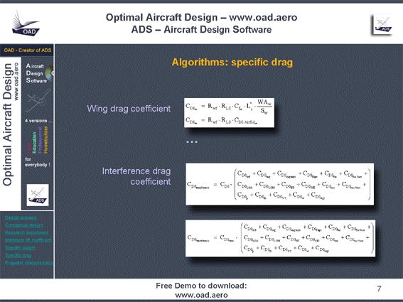
11 Specific drags A traditional drag breakdown is made as follows: - CD0 : zero-lift drag (friction drag), - CDL : induced drag, - CDint : interference drag caused by interaction of the different parts of the aircraft. The drag coefficient is therefore: CD = CD0 + CDL + CDint. The total drag of the aircraft is calculated as the sum of the drag of each major part of the aircraft: wing, trailing edge devices, horizontal tailplane, vertical tailplane, foreplane (canard), fuselage, propulsion (engine installation), propeller, nacelle, landing gear, interference. During the conceptual design of the aircraft, the interference drag is difficult if not impossible to determine. ADS uses a method based on reference aircraft as described below: - The designer has specified the aerodynamic quality of the aircraft for the design flight condition being considered. This value was determined from the analysis of similar aircraft. As a reminder, the aerodynamic quality is the total drag coefficient of the aircraft. - During the design process, the drag breakdown for the major aircraft components is initially worked out for the design flight condition. - Next, the interference drag is computed for the design flight condition by subtracting the total drag (the aerodynamic quality specified by the designer) and the sum of the drag breakdown calculated above. - Then, the relative interference drag is calculated and expressed as a fraction of the total drag. It is assumed that the relative intereference drag is constant for all flight conditions.
12

13 Propeller characteristics The propeller properties (diameter, pitch, number of blades, blade section) are determined using Propeller chart extracted from NACA reports. A blind test has been conducted with MT-Propeller in Germany. We sent to them the propeller specifications. They calculated the new propeller using their own methods and, in our side, we calculated the new propeller using ADS. The results concerning the propeller efficiency was as close as 0,1 percent. So we can claim that the methods we use to compute the characteristics of the propeller are very correct!
2 Aircraft Design Sequence
 2-1 2 Aircraft Design Sequence The sequence of activities during the project phase (see Fig. 1.3) can be divided in two steps: 1.) preliminary sizing 2.) conceptual design. Beyond this there is not much
What s New in AAA? Design Analysis Research. Version 3.3. February 2011
 Design Analysis Research What s New in AAA? Version 3.3 February 2011 AAA 3.3 contains various enhancements and revisions to version 3.2 as well as bug fixes. This version has 287,000 lines of code and
AERODYNAMIC DESIGN OF FLYING WING WITH EMPHASIS ON HIGH WING LOADING
 AERODYNAMIC DESIGN OF FLYING WING WITH EMPHASIS ON HIGH WING LOADING M. Figat Warsaw University of Technology Keywords: Aerodynamic design, CFD Abstract This paper presents an aerodynamic design process
Impact of Computational Aerodynamics on Aircraft Design
 Impact of Computational Aerodynamics on Aircraft Design Outline Aircraft Design Process Aerodynamic Design Process Wind Tunnels &Computational Aero. Impact on Aircraft Design Process Revealing details
Incompressible Potential Flow. Panel Methods (3)
") Incompressible Potential Flow Panel Methods (3) Outline Some Potential Theory Derivation of the Integral Equation for the Potential Classic Panel Method Program PANEL Subsonic Airfoil Aerodynamics Issues
Incompressible Potential Flow Panel Methods (3) Outline Some Potential Theory Derivation of the Integral Equation for the Potential Classic Panel Method Program PANEL Subsonic Airfoil Aerodynamics Issues
Design and Development of Unmanned Tilt T-Tri Rotor Aerial Vehicle
 Design and Development of Unmanned Tilt T-Tri Rotor Aerial Vehicle K. Senthil Kumar, Mohammad Rasheed, and T.Anand Abstract Helicopter offers the capability of hover, slow forward movement, vertical take-off
12. Digitizer Introduction. Digitizer
 12. Digitizer 12.1 Introduction The Digitizer module is a tool that has been developed to: 1. Use quickly and efficiently all the information contained in a 3 views drawing. - To measure distances - To
Aerodynamics of 3D Lifting Surfaces through Vortex Lattice Methods. Introduction to Applications of VLM
 Aerodynamics of 3D Lifting Surfaces through Vortex Lattice Methods Introduction to Applications of VLM Basic Concepts Boundary conditions on the mean surface Vortex Theorems, Biot-Savart Law The Horseshoe
APP 6.0 Quick Start Version 1.0 January 2013
 APP 6.0 Quick Start Version 1.0 January 2013 Quick Start 1 Introduction 1.1 Overview 1.1.1 The ALR Aerospace Flight Performance Program The software utility Aircraft Performance Program (APP) was designed
An efficient method for predicting zero-lift or boundary-layer drag including aeroelastic effects for the design environment
 The Aeronautical Journal November 2015 Volume 119 No 1221 1451 An efficient method for predicting zero-lift or boundary-layer drag including aeroelastic effects for the design environment J. A. Camberos
Design and Optimization of SUAV Empennage
 From the SelectedWorks of Innovative Research Publications IRP India Summer June 1, 2015 Design and Optimization of SUAV Empennage Innovative Research Publications, IRP India, Innovative Research Publications
Exploration of distributed propeller regional aircraft design
 Exploration of distributed propeller regional aircraft design Baizura Bohari 1,2, Emmanuel Benard 1, Murat Bronz 2 1 University of Toulouse - ISAE Supaero, Dept. of Aeronautic and Space Vehicles Design
APP - Aircraft Performance Program
 Introduction APP - Aircraft Performance Program Introduction APP is an aircraft-performance calculation program, specifically designed to provide a fast and easy way to evaluate aircraft performance. Another
Aircraft Stability and Performance 2nd Year, Aerospace Engineering. Dr. M. Turner
 Aircraft Stability and Performance 2nd Year, Aerospace Engineering Dr. M. Turner Basic Info Timetable 15.00-16.00 Monday ENG LT1 16.00-17.00 Monday ENG LT1 Typical structure of lectures Part 1 Theory Part
Post Stall Behavior of a Lifting Line Algorithm
 Post Stall Behavior of a Lifting Line Algorithm Douglas Hunsaker Brigham Young University Abstract A modified lifting line algorithm is considered as a low-cost approach for calculating lift characteristics
Introduction. AirWrench Operation
 Introduction AirWrench is a user-friendly software tool for creating flight dynamics for Microsoft Flight Simulator. AirWrench is not a traditional air file editor it compiles a complete air file, the
LAMDES User s Manual VLMpc
 LAMDES User s Manual This is a modified version of John Lamar s design program (Ref. 1). It is based on the vortex lattice program VLMpc, but converted to do design and optimization. Basic capabilities
THE JOINED WING SCALED DEMONSTRATOR RESULTS OF CFD
 THE JOINED WING SCALED DEMONSTRATOR RESULTS OF CFD Adam Dziubiński*, Sara Kuprianowicz*, Katarzyna Surmacz*, Cezary Galiński*, Jerzy Żółtak* *Instytut Lotnictwa Keywords: computational aerodynamics, joined
APP 6.0 Quick Start Manual
 APP 6.0 Quick Start Manual Quick Start Manual Information in this document is subject to change without notice. No part of this document may be reproduced or transmitted in any form or by any means, electronic
Introduction. AirWizEd User Interface
 Introduction AirWizEd is a flight dynamics development system for Microsoft Flight Simulator (MSFS) that allows developers to edit flight dynamics files in detail, while simultaneously analyzing the performance
RESPONSE SURFACE APPROXIMATIONS FOR PITCHING MOMENT INCLUDING PITCH-UP IN THE MULTIDISCIPLINARY DESIGN OPTIMIZATION OF A HIGH-SPEED CIVIL TRANSPORT
 RESPONSE SURFACE APPROXIMATIONS FOR PITCHING MOMENT INCLUDING PITCH-UP IN THE MULTIDISCIPLINARY DESIGN OPTIMIZATION OF A HIGH-SPEED CIVIL TRANSPORT by Paul J. Crisafulli Thesis submitted to the faculty
AeroPack User s Manual
 AeroPack User s Manual Design Analysis Research AeroPack User s Manual for Shark & Shark FX The software described in this document is furnished under a license agreement. The software may be used or
CFD Analysis of conceptual Aircraft body
 CFD Analysis of conceptual Aircraft body Manikantissar 1, Dr.Ankur geete 2 1 M. Tech scholar in Mechanical Engineering, SD Bansal college of technology, Indore, M.P, India 2 Associate professor in Mechanical
Optimate CFD Evaluation Optimate Glider Optimization Case
 Optimate CFD Evaluation Optimate Glider Optimization Case Authors: Nathan Richardson LMMFC CFD Lead 1 Purpose For design optimization, the gold standard would be to put in requirements and have algorithm
DYNAMICS OF A VORTEX RING AROUND A MAIN ROTOR HELICOPTER
 DYNAMICS OF A VORTEX RING AROUND A MAIN ROTOR HELICOPTER Katarzyna Surmacz Instytut Lotnictwa Keywords: VORTEX RING STATE, HELICOPTER DESCENT, NUMERICAL ANALYSIS, FLOW VISUALIZATION Abstract The main goal
A Cooperative Approach to Multi-Level Multi-Disciplinary Aircraft Optimization
 www.dlr.de Chart 1 ECCOMAS 2016, Greece, Crete, June 5-10, 2016 A Cooperative Approach to Multi-Level Multi-Disciplinary Aircraft Optimization Caslav Ilic, Mohammad Abu-Zurayk Martin Kruse, Stefan Keye,
Experimental study of UTM-LST generic half model transport aircraft
 IOP Conference Series: Materials Science and Engineering PAPER OPEN ACCESS Experimental study of UTM-LST generic half model transport aircraft To cite this article: M I Ujang et al 2016 IOP Conf. Ser.:
Self-Designing Parametric Geometries
 AIAA SciTech 5-9 January 2015, Kissimmee, Florida 56th AIAA/ASCE/AHS/ASC Structures, Structural Dynamics, and Materials Conference AIAA 2015-0396 Self-Designing Parametric Geometries András Sóbester University
Aerodynamic Design of a Tailless Aeroplan J. Friedl
 Acta Polytechnica Vol. 4 No. 4 5/2 Aerodynamic Design of a Tailless Aeroplan J. Friedl The paper presents an aerodynamic analysis of a one-seat ultralight (UL) tailless aeroplane named L2k, with a very
OpenVSP: Parametric Geometry for Conceptual Aircraft Design. Rob McDonald, Ph.D. Associate Professor, Cal Poly
 OpenVSP: Parametric Geometry for Conceptual Aircraft Design Rob McDonald, Ph.D. Associate Professor, Cal Poly 1 Vehicle Sketch Pad (VSP) Rapid parametric geometry for design NASA developed & trusted tool
Aerodynamic Analysis of Forward Swept Wing Using Prandtl-D Wing Concept
 Aerodynamic Analysis of Forward Swept Wing Using Prandtl-D Wing Concept Srinath R 1, Sahana D S 2 1 Assistant Professor, Mangalore Institute of Technology and Engineering, Moodabidri-574225, India 2 Assistant
(c)2002 American Institute of Aeronautics & Astronautics or Published with Permission of Author(s) and/or Author(s)' Sponsoring Organization.
2002 American Institute of Aeronautics & Astronautics or Published with Permission of Author(s) and/or Author(s)' Sponsoring Organization.") VIIA Adaptive Aerodynamic Optimization of Regional Introduction The starting point of any detailed aircraft design is (c)2002 American Institute For example, some variations of the wing planform may become
VIIA Adaptive Aerodynamic Optimization of Regional Introduction The starting point of any detailed aircraft design is (c)2002 American Institute For example, some variations of the wing planform may become
AERODYNAMIC DESIGN OF THE STRAKE FOR THE ROCKET PLANE IN TAILLESS CONFIGURATION.
 AERODYNAMIC DESIGN OF THE STRAKE FOR THE ROCKET PLANE IN TAILLESS CONFIGURATION. M. Figat, A. Kwiek, K. Seneńko Warsaw University of Technology Keywords: Optimization, gradient method, strake, CFD Abstract
VARIABLE-COMPLEXITY RESPONSE SURFACE APPROXIMATIONS FOR AERODYNAMIC PARAMETERS IN HSCT OPTIMIZATION
 VARIABLE-COMPLEXITY RESPONSE SURFACE APPROXIMATIONS FOR AERODYNAMIC PARAMETERS IN HSCT OPTIMIZATION By Oleg B. Golovidov athesissubmittedtothefacultyof virginia polytechnic institute and state university
Estimating Vertical Drag on Helicopter Fuselage during Hovering
 Estimating Vertical Drag on Helicopter Fuselage during Hovering A. A. Wahab * and M.Hafiz Ismail ** Aeronautical & Automotive Dept., Faculty of Mechanical Engineering, Universiti Teknologi Malaysia, 81310
Weight Estimation Using CAD In The Preliminary Rotorcraft Design
 Weight Estimation Using CAD In The Preliminary Rotorcraft Design M. Emre Gündüz 1, Adeel Khalid 2, Daniel P. Schrage 3 1 Graduate Research Assistant, Daniel Guggenheim School of Aerospace Engineering,
A New Conceptual Design Tool for General Aviation Aircraft (FLEX)
") A New Conceptual Design Tool for General Aviation Aircraft (FLEX) Ammar Salaymeh Linköpings universitet Institutionen för ekonomisk och industriell utveckling Examensarbete 2018 LIU-IEI-TEK-A 18/03151-SE
A New Conceptual Design Tool for General Aviation Aircraft (FLEX) Ammar Salaymeh Linköpings universitet Institutionen för ekonomisk och industriell utveckling Examensarbete 2018 LIU-IEI-TEK-A 18/03151-SE
Keywords: CFD, aerofoil, URANS modeling, flapping, reciprocating movement
 L.I. Garipova *, A.N. Kusyumov *, G. Barakos ** * Kazan National Research Technical University n.a. A.N.Tupolev, ** School of Engineering - The University of Liverpool Keywords: CFD, aerofoil, URANS modeling,
AERODYNAMIC DESIGN FOR WING-BODY BLENDED AND INLET
 25 TH INTERNATIONAL CONGRESS OF THE AERONAUTICAL SCIENCES AERODYNAMIC DESIGN FOR WING-BODY BLENDED AND INLET Qingzhen YANG*,Yong ZHENG* & Thomas Streit** *Northwestern Polytechincal University, 772,Xi
ME 435 Spring Project Design and Management II. Old Dominion University Department of Mechanical Engineering. Standard Dynamics Model
 ME 435 Spring 2011 Project Design and Management II Old Dominion University Department of Mechanical Engineering Standard Dynamics Model William Lawrence Andrew Snead TJ Wignall 15 March 2011 Abstract
Validation of a numerical simulation tool for aircraft formation flight.
 Validation of a numerical simulation tool for aircraft formation flight. T. Melin Fluid and Mechatronic Systems, Department of Management and Engineering, the Institute of Technology, Linköping University,
Mechanism Kinematics and Dynamics
 Mechanism Kinematics and Dynamics Final Project 1. The window shield wiper For the window wiper, (1). Select the length of all links such that the wiper tip X p (t) can cover a 120 cm window width. (2).
Accepted Manuscript. Jetstream 31 national flying laboratory: Lift and drag measurement and modelling
 Accepted Manuscript Jetstream 31 national flying laboratory: Lift and drag measurement and modelling N.J. Lawson, H. Jacques, J.E. Gautrey, A.K. Cooke, J.C. Holt, K.P. Garry PII: S1270-9638(16)30338-8
State of the art at DLR in solving aerodynamic shape optimization problems using the discrete viscous adjoint method
 DLR - German Aerospace Center State of the art at DLR in solving aerodynamic shape optimization problems using the discrete viscous adjoint method J. Brezillon, C. Ilic, M. Abu-Zurayk, F. Ma, M. Widhalm
Status of Gradient-based Airframe MDO at DLR The VicToria Project
 DLR.de Chart 1 Status of Gradient-based Airframe MDO at DLR The VicToria Project M. Abu-Zurayk, C. Ilic, A. Merle, A. Stück, S. Keye, A. Rempke (Institute of Aerodynamics and Flow Technology) T. Klimmek,
HICON AERODYNAMICS - HIGH LIFT AERODYNAMIC DESIGN FOR THE FUTURE
 25 TH INTERNATIONAL CONGRESS OF THE AERONAUTICAL SCIENCES HICON AERODYNAMICS - HIGH LIFT AERODYNAMIC DESIGN FOR THE FUTURE Mark Sutcliffe*, Daniel Reckzeh*, Markus Fischer* *Aerodynamic Design and Data,
Software Requirements Specification
 NASA/TM-2001-210867 HSCT4.0 Application Software Requirements Specification A. O. Salas, J. L. Walsh, B. H. Mason, R. P. Weston, J. C. Townsend, J. A. Samareh, and L. L. Green Langley Research Center,
AN INSTRUCTIVE ALGORITHM FOR AIRCRAFT ELEVATOR SIZING TO BE USED IN PRELIMINARY AIRCRAFT DESIGN SOFTWARE
 Original Scientific Paper doi:10.5937/jaes15-14829 Paper number: 15(2017)4, 476, 489-494 AN INSTRUCTIVE ALGORITHM FOR AIRCRAFT ELEVATOR SIZING TO BE USED IN PRELIMINARY AIRCRAFT DESIGN SOFTWARE Omran Al-Shamma
Critical Design Review. Almog Dov Assaf Aloush Bar Ovadia Dafna Lavi Orad Eldar. Supervisor: Dror Artzi
 Critical Design Review Almog Dov Assaf Aloush Bar Ovadia Dafna Lavi Orad Eldar Supervisor: Dror Artzi Man-portable UAV Over the hill / Urban surveillance Fast field deployment Endurance: 3 min Simple to
Optimisation of the Sekwa Blended-Wing-Body Research UAV
 Optimisation of the Sekwa Blended-Wing-Body Research UAV B.A. Broughton and R. Heise Council for Scientific and Industrial Research Pretoria, South Africa ABSTRACT A variable stability, blended-wing-body
MULTIDISCIPLINARY HIGH-FIDELITY ANALYSIS AND OPTIMIZATION OF AEROSPACE VEHICLES, PART 1: FORMULATION
 AIAA-2000-0418 MULTIDISCIPLINARY HIGH-FIDELITY ANALYSIS AND OPTIMIZATION OF AEROSPACE VEHICLES, PART 1: FORMULATION J. L. Walsh, * J. C. Townsend, A. O. Salas, J. A. Samareh, V. Mukhopadhyay, and J.-F.
PreSTo Wing Module Optimization for the Double Trapezoidal Wing
 PreSTo Wing Module Optimization for the Double Trapezoidal Wing Karunanidhi Ramachandran and Dieter Scholz Abstract This paper explains the Aircraft Preliminary Sizing Tool (PreSTo) developed at the Hamburg
Reference Resolution and Views Working Note 25
 Reference Resolution and Views Working Note 25 Peter Clark Knowledge Systems Boeing Maths and Computing Technology peter.e.clark@boeing.com May 2001 Abstract A common phenomenon in text understanding is
THE EFFECTS OF THE PLANFORM SHAPE ON DRAG POLAR CURVES OF WINGS: FLUID-STRUCTURE INTERACTION ANALYSES RESULTS
 March 18-20, 2013 THE EFFECTS OF THE PLANFORM SHAPE ON DRAG POLAR CURVES OF WINGS: FLUID-STRUCTURE INTERACTION ANALYSES RESULTS Authors: M.R. Chiarelli, M. Ciabattari, M. Cagnoni, G. Lombardi Speaker:
AERONAUTICAL RESEARCH JOURNAL Name
 AERONAUTICAL RESEARCH JOURNAL Name June 2013 Edition Brooklyn Aerodrome Flight School 2 Table of Contents 1 Paper Airplanes... 5 Research: Describing Flight... 6 Experiment: Bullet vs. Dart... 7 Design:
Parametric Geometry for Propulsion-Airframe Integration
 Parametric Geometry for Propulsion-Airframe Integration NASA NRA NNX11AI70A Topic 2.2 Russell K. Denney Jimmy C. Tai Dimitri N. Mavris Georgia Institute of Technology Atlanta, GA 30332 Outline Objective
LESSONS FROM WIND TUNNEL MODELS MADE BY RAPID PROTOTYPING
 LESSONS FROM WIND TUNNEL MODELS MADE BY RAPID PROTOTYPING Ehud Kroll Faculty of Aerospace Engineering Technion Israel Institute of Technology Technion City, Haifa 32000, Israel Dror Artzi Faculty of Aerospace
CAD-BASED WORKFLOWS. VSP Workshop 2017
 CAD-BASED WORKFLOWS VSP Workshop 2017 RESEARCH IN FLIGHT COMPANY Established 2012 Primary functions are the development, marketing and support of FlightStream and the development of aerodynamic solutions
Single and multi-point aerodynamic optimizations of a supersonic transport aircraft using strategies involving adjoint equations and genetic algorithm
 Single and multi-point aerodynamic optimizations of a supersonic transport aircraft using strategies involving adjoint equations and genetic algorithm Prepared by : G. Carrier (ONERA, Applied Aerodynamics/Civil
Rapid Design and Virtual Testing of UAV Within the DEE Framework
 Rapid Design and Virtual Testing of UAV Within the DEE Framework MASTER OF SCIENCE THESIS For obtaining the degree of Master of Science in Aerospace Engineering at Delft University of Technology Vinodh
AVIONICS FUNDAMENTALS MAINTENANCE TRAINING /27/2006 Chapter 5 - Inertial Reference
 Gyros Inside Indicators Figures 5-4 and 5-5 illustrate how gyros can be used inside indicators mounted directly on the flight instrument panel. Figure 5-4 shows a gyro mounted with its spin axis vertical.
Integrated Computational and Experimental Studies of Flapping-wing Micro Air Vehicle Aerodynamics
 Integrated Computational and Experimental Studies of Flapping-wing Micro Air Vehicle Aerodynamics Kevin Knowles, Peter Wilkins, Salman Ansari, Rafal Zbikowski Department of Aerospace, Power and Sensors
machine design, Vol.6(2014) No.3, ISSN pp
 No.3, ISSN pp") machine design, Vol.6(2014) No.3, ISSN 1821-1259 pp. 71-78 Original scientific paper DETERMINATION OF AERODYNAMIC CHARACTERISTICS OF A LIGHT AIRCRAFT USING VISCOUS CFD MODELING Zoran STEFANOVIĆ 1 - Ivan
machine design, Vol.6(2014) No.3, ISSN 1821-1259 pp. 71-78 Original scientific paper DETERMINATION OF AERODYNAMIC CHARACTERISTICS OF A LIGHT AIRCRAFT USING VISCOUS CFD MODELING Zoran STEFANOVIĆ 1 - Ivan
Conceptual design, Structural and Flow analysis of an UAV wing
 IOSR Journal of Mechanical and Civil Engineering (IOSR-JMCE) e-issn: 2278-1684,p-ISSN: 2320-334X, Volume 13, Issue 3 Ver. IV (May- Jun. 2016), PP 78-87 www.iosrjournals.org Conceptual design, Structural
CFD++ APPLICATION ON WIND TUNNEL DATA ANALYSIS
 CFD++ APPLICATION ON WIND TUNNEL DATA ANALYSIS Introduction Piaggio Aero Industries is actually studing a new mid size jet for civilian use. Many people and many disciplines are implicated but up to now
NAVAIR Use of OpenVSP
 NAVAIR 4.0M.1.5 NAVAIR Use of OpenVSP Presented to: OpenVSP Workshop 29 Aug 2017 Presented by: AJ Field AIR-4.0M Public Release Authorization 2017-611. 1 Agenda Agenda Role of NAVAIR Conceptual Aircraft
CAPE. Community Behavioral Health Data. How to Create CAPE. Community Assessment and Education to Promote Behavioral Health Planning and Evaluation
 CAPE Community Behavioral Health Data How to Create CAPE Community Assessment and Education to Promote Behavioral Health Planning and Evaluation i How to Create County Community Behavioral Health Profiles
Mechanism Kinematics and Dynamics
 Mechanism Kinematics and Dynamics Final Project Presentation 10:10-13:00, 12/21 and 12/28 1. The window shield wiper (2) For the window wiper in Fig.1.33 on p.26 of the PPT, (1). Select the length of all
USE OF ADAMS IN DYNAMIC SIMULATION OF LANDING GEAR RETRACTION AND EXTENSION
 USE OF ADAMS IN DYNAMIC SIMULATION OF LANDING GEAR RETRACTION AND EXTENSION Author : O. NOEL Messier-Dowty SA (Velizy, France) 1. ABSTRACT This paper presents the method in use at Messier-Dowty SA during
OPTIMISATION OF THE HELICOPTER FUSELAGE WITH SIMULATION OF MAIN AND TAIL ROTOR INFLUENCE
 28 TH INTERNATIONAL CONGRESS OF THE AERONAUTICAL SCIENCES OPTIMISATION OF THE HELICOPTER FUSELAGE WITH Wienczyslaw Stalewski*, Jerzy Zoltak* * Institute of Aviation, Poland stal@ilot.edu.pl;geor@ilotl.edu.pl
The calculation of the short period and phugoid mode properties of an aircraft, eg. the natural frequency and the damping ratio.
 Chapter 4 Mathematical Model A mathematical model of aircraft dynamics is required to study handling qualities. The mathematical models described in this chapter will be used to perform the following two
Computer Aided Design Analysis of Aircraft Wing Using Cad Software
 Computer Aided Design Analysis of Aircraft Wing Using Cad Software Mohd Mansoor Ahmed M.Tech, Dept of Mechanical Engineering, Syed Hashim College of Science &Technology, Pregnapur, Medak District. Abstract:
Inaugural OpenVSP Workshop
 Inaugural OpenVSP Workshop Rob McDonald San Luis Obispo August 22, 2012 Geometry as Origin of Analysis (Design) Shape is fundamental starting point for physics-based analysis Aerodynamics Structures Aeroelasticity
STRUCTURAL MODELING AND OPENVSP
 OpenVSP Workshop 2015 Hampton, Virginia August 11-13, 2015 STRUCTURAL MODELING AND OPENVSP Overview Presentation Trevor Laughlin trevor@laughlinresearch.com INTRODUCTION Professional Experience Managing
Analysis of Hydraulic Turbine using MecaFlux Heliciel
 Analysis of Hydraulic Turbine using MecaFlux Heliciel Suppose that we have a stream of water with no head available then for getting power out of it we can just only use the kinetic energy of water. P
A CONCEPTUAL DESIGN PLATFORM FOR BLENDED- WING-BODY TRANSPORTS
 A CONCEPTUAL DESIGN PLATFORM FOR BLENDED- WING-BODY TRANSPORTS Minghui Zhang, Zhenli Chen, Binqian Zhang School of Aeronautics, Northwestern Polytechnical University, Xi an, Shaanxi, China Keywords: blended-wing-body
The Role of Geometry in the Multidisciplinary Design of Aerospace Vehicles
 The Role of Geometry in the Multidisciplinary Design of Aerospace Vehicles SIAM Conference on Geometric Design Thomas A. Zang & Jamshid A. Samareh Multidisciplinary Optimization Branch NASA Langley Research
Physics of an Flow Over a Wing
 Wings in Ideal Flow Physics of an Flow Over a Wing Werle, 1974, NACA 0012, 12.5 o, AR=4, Re=10000 Bippes, Clark Y, Rectangular Wing 9 o, AR=2.4, Re=100000 Head, 1982, Rectangular Wing, 24 o, Re=100000
AEDsys Program. User Guide
 AEDsys Program User Guide Version 3.1 May 17, 2003 Copyright 2002 - Jack D Mattingly, Ph.D. Table of Contents 1. General Description of Program 3 2. Main Window 3 3. Constraint Analysis 7 4. Contour Plots
Project 012 Aircraft Design and Performance Tool Connectivity with AEDT
 Project 012 Aircraft Design and Performance Tool Connectivity with AEDT Stanford University Project Lead Investigator Juan J. Alonso (PI) Professor Department of Aeronautics & Astronautics Stanford University
Designing flapping wings as oscillating structures
 th World Congress on Structural and Multidisciplinary Optimization May 9-4,, Orlando, Florida, USA Designing flapping wings as oscillating structures Zhiyuan Zhang, Ashok V. Kumar, Raphael T. Haftka University
Make to Innovate Cardinal Flight Aerodynamics Team
 Make to Innovate Cardinal Flight Aerodynamics Team Group Members: Alexander Scott Benjamin Vanduyne Brandon Ganey Joseph Cairo Lyle Sorensen 1 Abstract The purpose for this milestone was to construct an
The Use of Computational Fluid Dynamics In the Aerospace Industry Past Present - Future
 The Use of Computational Fluid Dynamics In the Aerospace Industry Past Present - Future Douglas N. Ball Aerospace Consultant 1 The Early Days Not much CFD in these old birds! Great airplanes none the less.
MSC Software Aeroelastic Tools. Mike Coleman and Fausto Gill di Vincenzo
 MSC Software Aeroelastic Tools Mike Coleman and Fausto Gill di Vincenzo MSC Software Confidential 2 MSC Software Confidential 3 MSC Software Confidential 4 MSC Software Confidential 5 MSC Flightloads An
INVESTIGATION ON STRUCTURAL ASPECTS OF UNMANNED COMBAT AIR VEHICLE FOR AEROELASTIC ANALYSIS P N Vinay *, P V Srihari *, A Mahadesh Kumar
 Research Article INVESTIGATION ON STRUCTURAL ASPECTS OF UNMANNED COMBAT AIR VEHICLE FOR AEROELASTIC ANALYSIS P N Vinay *, P V Srihari *, A Mahadesh Kumar Address for Correspondence * Dept. of Mechanical
QBlade Short Manual v0.8 David Marten david.marten(at)tu-berlin.de
tu-berlin.de") QBlade Short Manual v0.8 David Marten david.marten(at)tu-berlin.de Contents Introduction... 2 Changes in v.08... 2 Data Structure... 3 General User Interface... 4 Airfoil Design... 6 Direct Airfoil Analysis...
QBlade Short Manual v0.8 David Marten david.marten(at)tu-berlin.de Contents Introduction... 2 Changes in v.08... 2 Data Structure... 3 General User Interface... 4 Airfoil Design... 6 Direct Airfoil Analysis...
Aerodynamics of 3D Lifting Surfaces through Vortex Lattice Methods (3) Two implementations of the VLM
 Two implementations of the VLM") Aerodynamics of 3D Lifting Surfaces through Vortex Lattice Methods (3) Two implementations of the VLM Basic Concepts Outline Boundary conditions on the mean surface Vortex Theorems, Biot-Savart Law The
Aerodynamics of 3D Lifting Surfaces through Vortex Lattice Methods (3) Two implementations of the VLM Basic Concepts Outline Boundary conditions on the mean surface Vortex Theorems, Biot-Savart Law The
GRID PATTERN EFFECTS ON AERODYNAMIC CHARACTERISTICS OF GRID FINS
 24 TH INTERNATIONAL CONGRESS OF THE AERONAUTICAL SCIENCES GRID PATTERN EFFECTS ON AERODYNAMIC CHARACTERISTICS OF GRID FINS Fumiya Hiroshima, Kaoru Tatsumi* *Mitsubishi Electric Corporation, Kamakura Works,
A-7 Strut Braced Wing Concept Transonic Wing Design
 A-7 Strut Braced Wing Concept Transonic Wing Design by Andy Ko, William H. Mason, B. Grossman and J.A. Schetz VPI-AOE-275 July 12, 2002 Prepared for: National Aeronautics and Space Administration Langley
Applications of structural optimisation to AIRBUS A380 powerplant configuration and pylon design
 Applications of structural optimisation to AIRBUS A380 powerplant configuration and pylon design ABSTRACT 2001-122 Stéphane GRIHON AIRBUS 316, Route de Bayonne 31060 Toulouse CEDEX France stephane.grihon@airbus.aeromatra.com
Introduction to ANSYS CFX
 Workshop 03 Fluid flow around the NACA0012 Airfoil 16.0 Release Introduction to ANSYS CFX 2015 ANSYS, Inc. March 13, 2015 1 Release 16.0 Workshop Description: The flow simulated is an external aerodynamics
Volume 5, Issue 1 (2017) ISSN International Journal of Advance Research and Innovation
 ISSN International Journal of Advance Research and Innovation") Structural Design &Optimization Of An Unmanned Aerial Vehicle Wing For SAE Aero Design Challenge Harsh Raj Chauhan *, Harsh Panwar *, Vikas Rastogi Department of Mechanical Engineering, Delhi Technological
Structural Design &Optimization Of An Unmanned Aerial Vehicle Wing For SAE Aero Design Challenge Harsh Raj Chauhan *, Harsh Panwar *, Vikas Rastogi Department of Mechanical Engineering, Delhi Technological
Introduction CLASS 1 LED PRODUCT
 Introduction Thank you for purchasing a set of FlightLights, a high performance LED system for model aircraft designed and manufactured by BrainCube Aeromodels Ltd. This manual will describe how to safely
Multidisciplinary design optimization (MDO) of a typical low aspect ratio wing using Isight
 of a typical low aspect ratio wing using Isight") Multidisciplinary design optimization (MDO) of a typical low aspect ratio wing using Isight Mahadesh Kumar A 1 and Ravishankar Mariayyah 2 1 Aeronautical Development Agency and 2 Dassault Systemes India
Multidisciplinary design optimization (MDO) of a typical low aspect ratio wing using Isight Mahadesh Kumar A 1 and Ravishankar Mariayyah 2 1 Aeronautical Development Agency and 2 Dassault Systemes India
Lift Superposition and Aerodynamic Twist Optimization for Achieving Desired Lift Distributions
 48th AIAA Aerospace Sciences Meeting Including the New Horizons Forum and Aerospace Exposition 4-7 January 2010, Orlando, Florida AIAA 2010-1227 Lift Superposition and Aerodynamic Twist Optimization for
Introduction to CFX. Workshop 2. Transonic Flow Over a NACA 0012 Airfoil. WS2-1. ANSYS, Inc. Proprietary 2009 ANSYS, Inc. All rights reserved.
 Workshop 2 Transonic Flow Over a NACA 0012 Airfoil. Introduction to CFX WS2-1 Goals The purpose of this tutorial is to introduce the user to modelling flow in high speed external aerodynamic applications.
CFD ANALYSIS OF UAVs USING VORSTAB, FLUENT, AND ADVANCED AIRCRAFT ANALYSIS SOFTWARE. Benjamin Sweeten
 CFD ANALYSIS OF UAVs USING VORSTAB, FLUENT, AND ADVANCED AIRCRAFT ANALYSIS SOFTWARE BY Benjamin Sweeten Submitted to the graduate degree program in Aerospace Engineering and the Graduate Faculty of the
University of Texas VSP Structural Analysis Module Update - Demonstration
 University of Texas VSP Structural Analysis Module Update - Demonstration http://vspsam.ae.utexas.edu/ VSP Workshop, San Luis Obispo, CA Hersh Amin Armand J. Chaput Department of Aerospace Engineering
How to Enter and Analyze a Wing
 How to Enter and Analyze a Wing Entering the Wing The Stallion 3-D built-in geometry creation tool can be used to model wings and bodies of revolution. In this example, a simple rectangular wing is modeled
DOING MORE WITH EXCEL: MICROSOFT OFFICE 2013
 DOING MORE WITH EXCEL: MICROSOFT OFFICE 2013 GETTING STARTED PAGE 02 Prerequisites What You Will Learn MORE TASKS IN MICROSOFT EXCEL PAGE 03 Cutting, Copying, and Pasting Data Basic Formulas Filling Data