SOLIDWORKS: Lesson 1 - Basics and Modeling. Introduction to Robotics
|
|
|
- Geoffrey Preston
- 6 years ago
- Views:
Transcription
1 SOLIDWORKS: Lesson 1 - Basics and Modeling Fundamentals Introduction to Robotics
2 SolidWorks SolidWorks is a 3D solid modeling package which allows users to develop full solid models in a simulated environment for both design and analysis. In SolidWorks, you sketch ideas and experiment with different designs to create 3D models.
3 SolidWorks SolidWorks is used by students, designers, engineers, and other professionals to produce simple and complex parts, assemblies, and drawings. Designing in a modeling package such as SolidWorks is beneficial because it saves time, effort, and money that would otherwise be spent prototyping the design.
4 SolidWorks Components - PARTS Before we begin looking at the software, it is important to understand the different components that make up a SolidWorks model. The first, and most basic element of a SolidWorks model is a Part. Parts consist of primitive geometry and features such as extrudes, revolutions, lofts, sweeps, etc. Parts will be the building blocks for all of the models that you will create
.")
5 SolidWorks Components - Assemblies The second component is the assembly. Assemblies are collections of parts which are assembled in a particular fashion using mates (constraints). Any complex model will usually consist of one, or many assemblies.
 can recreate your part.")
6 SolidWorks Components - DRAWINGS The third, and final component in SolidWorks is the Drawing. A drawing is the typical way to represent a 3D model such that any engineer (or manufacturer) can recreate your part. Drawings are important because they provide a standard way of sharing your design.

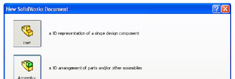
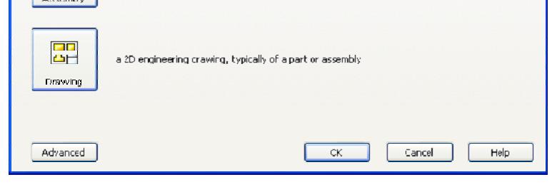
7 SolidWorks Let s Begin By default, no file is opened automatically when you start the program. To create a new file, click on File > New or click the New File icon in the main toolbar. This will open the New SolidWorks Document wizard.
8 SolidWorks Tour
9 SolidWorks Tour Let s begin by creating a new part. To do this, click on Part, then OK Once you do this, you will be brought into the modeling view which should open several toolbars and panes


10 SolidWorks Tour There are several important parts of the screen that needs to be identified before we continue. First, the left side of the First, the left side of the screen consists of several tabbed panes that provide very important information regarding your model.


11 SolidWorks Tour The first tab, called the Feature Manager, lists all features that have been created within your model. This tab is extremely important as it will be from here that you select and change features once they have been created.


12 SolidWorks Tour The second tab, called the Property Manager, allows you to adjust the properties of various entities either during construction, or once it has been created. Note that generally you will not need to manually change the tab on the manager window

13 SolidWorks Tour The third tab is called the Configuration Manager and is used to set up different view configurations such as exploded views or 3D section views. Usually this will be used once the part has been created and you wish to set up specific configurations for visualization.

14 SolidWorks Tour There may also be other tabs visible in the manager window. Generally any time you load an additional SolidWorks module (such as PhotoWorks, COSMOS Motion, COSMOS Works, etc.) it will create a new tab in this window.
15 SolidWorks Tour The next important feature of the interface is the dynamic Toolbar The dynamic Toolbar provides access to the most relevant, and frequently use commands in SolidWorks


16 SolidWorks Tour The last part of the interface which should be noted is the Task Pane on the right side of the screen. Using the Task Pane you can view content specific tasks such as importing standard geometry, file explorer, view palette, as well as any plug-in specific information.


17 SolidWorks Tour The last thing that needs to be shown is how to open the SolidWorks tutorials. They can be accessed by going to Help > SolidWorks Tutorials. The tutorials are very helpful and cover from the most basic features to more advanced analysis and assemblies
18 SolidWorks Exercise Now that we have explored the interface of SolidWorks, lets create a simple part step-bystep. For now, we are only going to concern ourselves with one type of feature: Extruded Boss/Base.


19 SolidWorks Exercise What is Extrude? Extrude When you take a 2D area and push the design out into another dimension. A 2D area, for example, can be made into a 3D volume by extruding it out a specific distance, d. You can extrude to make a SOLID or you can extrude to make a CUT
20 SolidWorks Exercise There are MANY ways to EXTRUDE a surface We could make this rectangle and EXTRUDE it DOWN or UP You could EXTRUDE this rectangle and pull it to the left or right Let s begin. Choose FILE, then NEW PART


21 SolidWorks Exercise We wish to model the following part: This is a basic 3 inch bar used often time to mount our wheels to our motors. It is obviously 3 inches long, yet inches in width. How do we make sure we use the correct UNITS?


22 SolidWorks Exercise In feature manager, RIGHT CLICK on PART1, then choose DOCUMENT PROPERTIES. Always remember to do this FIRST when making a new part. Click on UNITS, then choose IPS for inches. Then choose OK


23 SolidWorks Exercise Let s begin by selecting EXTRUDED Boss Base You should notice that your tab will change to property manager asking you to select a plane from the view.


24 SolidWorks Exercise Go ahead and select the horizontal plane shown. You should notice several things happen. 1. You switch to feature manager 2. You have sketch buttons on the dynamic toolbar 3. You view below is shown as TOP VIEW! You are looking down on top of the part.


25 SolidWorks Exercise Click on Rectangle. You should see your cursor change to a rectangle with a pencil which means you are sketching. Make a rectangle by dragging the mouse from one corner of the screen to the other. The size does not matter at this point. Click the GREEN CHECK in FEATURE MANAGER when complete.


26 SolidWorks Exercise If you hit escape, it will get you out of the rectangle TOOL and back to a normal cursor. We need DIMENSIONS to our rectangle however. At the bottom right of your screen you will see the figure above. Obviously, we are in the middle of our sketch but it also says, Under Defined. This means that there are parts of the sketch that are not defined according to location.


27 SolidWorks Exercise Click the bottom right point on the rectangle. You should be able to move this point around as its location is NOT defined. This point has degrees of freedom and is NOT constrained.


28 SolidWorks Exercise Let s save our work! Click on the small box next to the far right vertical line. Notice this box turns pink when clicked and that it has a vertical line in it. This means that this line is vertical and when you click on it you can move it left or right. The vertical lines can thus be moved up or down. Press the DELETE button, then click on the top right point. Notice the line is not defined as a vertical line anymore and the degrees of freedom are extended. The horizontal line still moves up or down, but notice the vertical line can be moved in any direction as you deleted the relationship.


29 SolidWorks Exercise You can add relations by clicking on a line, turns green. Line properties will appear and Line properties will appear and you can click on the VERTICAL button on the ADD RELATIONS windows to constrain the line to just the vertical direction.


30 SolidWorks Exercise Click on the RIGHT vertical line, then hold down the CTRL button. Click the left vertical line. You should see a list of available relations that you can add to BOTH line. Let s choose EQUAL and VERTICAL. Click the green check when finished. Do the same thing for the top and bottom horizontal line, except add a horizontal relation.


31 SolidWorks Exercise You should see tiny green boxes next to the lines. If you place your mouse over them it will tell you what relation that element has. Unfortunately, our design is still blue which means we are still UNDER DEFINED. In fact, we need to fix our design to the origin in some way. Depending on what design aspect come later it is often desired to fix the origin at the CENTER of the design. RIGHT CLICK on the bottom horizontal line and choose SELECT MIDPOINT. Hold down CTRL and select the ORIGIN. Add a vertical relation. Do the same thing for the sides by adding a horizontal relation to the origin.

32 SolidWorks Exercise Now we want to add specific dimensions to our drawing. Choose SMART DIMENSION on the dynamic toolbar. Click the bottom horizontal line of our rectangle and drag the dimension down. You can change the length of the line by using the slider bar or you can simply enter in 3 inches in the box shown. Enter the value 3 then click the green check. If the box is way too big or small, press f on the keyboard to fit.


33 SolidWorks Exercise Now using Smart Dimension again lets dimension the left vertical line.. Modify the Length to be units as shown in Hit f on the keyboard to view the design the original drawing. better


34 SolidWorks Exercise Notice that after you added relations and added dimensions the design color turned black. This means it is FULLY DEFINED. ONLY after seeing this can we then EXTRUDE. Click in the top right corner to EXIT the SKETCH. If you hit EXTRUDE earlier, the part will automatically become 3D. If not, click on the part in feature manager then click EXTRUDE BOSS/BASE at the top.


35 SolidWorks Exercise After EXTRUDE was chose, the PROPERTY MANAGER should have opened. In the BOX, D1 it is asking for a width distance. Since the width and thickness are the same we will enter in. Click the green check to finish and view the finished part.
36 SolidWorks Exercise To ZOOM you can use the mouse wheel or hit the Shift button and move mouse To ROTATE, press in the mouse wheel and hold. To PAN you use the Ctrl button and move mouse To fit a picture to a window simply press the f letter key on the keyboard to FIT.
37 Mechanical Drawings So far we have been dealing with creating parts and assemblies in SolidWorks, however, when you go to get a part machined, you will need to create a mechanical drawing of each of your parts (and assemblies). Mechanical drawings are important because they allow those who are technically trained to reconstruct your 3D geometry from 2D drawings.
38 Drawings in Solidworks Fortunately, SolidWorks makes it very easy for us to create drawings from a part or assembly file. In fact, if built properly, SolidWorks will also dimension the entire part and assembly for us something that saves a lot of time!

39 Drawings in Solidworks Once we open or finish the part, we choose make drawing from part from the file menu at the top which will automatically create a drawing file from our part: Let s do this! If it asks you to save then save your file.

40 Drawing Format At first you see several different formats that are set up for you. Choose A-Landscape.
41 Drawings in Solidworks However, before we can begin placing views, it is important to set our projection style to Third Angle (in order to have the projections behave as we expect) To do this, right click anywhere on the sheet and click on Properties (or you can right click on the sheet in the Feature Manager)


42 Drawings in Solidworks This will open the Sheet Properties window:


43 Drawings in Solidworks Open up the palette on the RIGHT side menu Click and HOLD the view you want and drag it into the drawing field. Choose the FRONT view and drag it Choose the FRONT view and drag it to the bottom right of the drawing field.


44 Drawings in Solidworks As soon as the front view is in position move the mouse UPWARD. You will see another design, this is actually the TOP view. Click to place the top view then return to the front view and move the mouse sideways. Repeat, then go diagonal. Click the green check when finished.

45 Drawings in Solidworks You should now see 4 views (front, top, side, & isometric).


46 Drawings in Solidworks Click on the ISOMETRIC view, then choose SHADED WITH EDGES under DISPLAY STYLE on the left. In drawings, we always shade in the ISOMETRIC view


47 Drawings in Solidworks Click on the FRONT VIEW, then within the ANNOTATIONS tab at the top click on MODEL ITEMS. Under source/destination choose, entire model from the drop down menu. Then check the box, import items into all views. Dimensions will then be added to the drawing. If you don t see dimensions on each view, try adding them separately.


48 Drawings in Solidworks Save the drawing, then print it out. Write your name in the title block in the bottom right.
SOLIDWORKS: Lesson 1 - Basics and Modeling. UCF Engineering
 SOLIDWORKS: Lesson 1 - Basics and Modeling Fundamentals UCF Engineering SolidWorks SolidWorks is a 3D solid modeling package which allows users to develop full solid models in a simulated environment for
Introduction to SolidWorks Basics Materials Tech. Wood
 Introduction to SolidWorks Basics Materials Tech. Wood Table of Contents Table of Contents... 1 Book End... 2 Introduction... 2 Learning Intentions... 2 Modelling the Base... 3 Modelling the Front... 10
SOLIDWORKS: Lesson III Patterns & Mirrors. UCF Engineering
 SOLIDWORKS: Lesson III Patterns & Mirrors UCF Engineering Solidworks Review Last lesson we discussed several more features that can be added to models in order to increase their complexity. We are now
Introduction to SolidWorks for Technology. No1: Childs Toy
 Introduction to SolidWorks for Technology No1: Childs Toy Table of Contents Table of Contents... 1 Introduction... 2 Part Modelling: Cab... 3 Part Modelling: Base... 6 Part Modelling: Wheel... 12 Assembly:
Battery Holder. Chapter 9. Boat. A. Front Extrude. Step 1. Click File Menu > New, click Part and OK. SolidWorks 10 BATTERY HOLDER AA BOAT Page 9-1
 Chapter 9 Boat Battery Holder A. Front Extrude. Step 1. Click File Menu > New, click Part and OK. AA Step 2. Click Front (plane) in the Feature Manager and click Sketch from the Content toolbar, Fig. 1.
SolidWorks 2½D Parts
 SolidWorks 2½D Parts IDeATe Laser Micro Part 1b Dave Touretzky and Susan Finger 1. Create a new part In this lab, you ll create a CAD model of the 2 ½ D key fob below to make on the laser cutter. Select
SolidWorks Intro Part 1b
 SolidWorks Intro Part 1b Dave Touretzky and Susan Finger 1. Create a new part We ll create a CAD model of the 2 ½ D key fob below to make on the laser cutter. Select File New Templates IPSpart If the SolidWorks
Memo Block. This lesson includes the commands Sketch, Extruded Boss/Base, Extruded Cut, Shell, Polygon and Fillet.
 Commands Used New Part This lesson includes the commands Sketch, Extruded Boss/Base, Extruded Cut, Shell, Polygon and Fillet. Click File, New on the standard toolbar. Select Part from the New SolidWorks
ME009 Engineering Graphics and Design CAD 1. 1 Create a new part. Click. New Bar. 2 Click the Tutorial tab. 3 Select the Part icon. 4 Click OK.
 PART A Reference: SolidWorks CAD Student Guide 2014 2 Lesson 2: Basic Functionality Active Learning Exercises Creating a Basic Part Use SolidWorks to create the box shown at the right. The step-by-step
Autodesk Inventor - Basics Tutorial Exercise 1
 Autodesk Inventor - Basics Tutorial Exercise 1 Launch Inventor Professional 2015 1. Start a New part. Depending on how Inventor was installed, using this icon may get you an Inch or Metric file. To be
Skateboard. Hanger. in the Feature Manager and click Sketch on the Context toolbar, Fig. 1. Fig. 2
 Chapter 3 Skateboard Hanger A. Sketch1 Lines. Step 1. Click File Menu > New, click Part Metric and OK. Step 2. Click Right Plane in the Feature Manager and click Sketch on the Context toolbar, Fig. 1.
Body. Chapter 1. Simple Machines. A. New Part. Step 1. Click File Menu > New.
 Chapter 1 A. New Part. Step 1. Click File Menu > New. Simple Machines Body Step 2. Click Part from the list and click OK, Fig. 1. B. Sketch Construction Rectangle. Step 1. Click Right Plane in the Feature
Solar Car. Chassis. in the Feature Manager and click Sketch from the Content toolbar, Fig. 2. Origin. on the Command Manager toolbar. Fig.
 Chapter 1 A. New Part. Step 1. Click File Menu > New. Solar Car Chassis Step 2. Click Part from the list and click OK, Fig. 1. B. Sketch Chassis. Step 1. Click Right Plane in the Feature Manager and click
Chapter 2 Parametric Modeling Fundamentals
 2-1 Chapter 2 Parametric Modeling Fundamentals Create Simple Extruded Solid Models Understand the Basic Parametric Modeling Procedure Create 2-D Sketches Understand the Shape before Size Approach Use the
TUTORIAL 2. OBJECTIVE: Use SolidWorks/COSMOS to model and analyze a cattle gate bracket that is subjected to a force of 100,000 lbs.
 TUTORIAL 2 OBJECTIVE: Use SolidWorks/COSMOS to model and analyze a cattle gate bracket that is subjected to a force of 100,000 lbs. GETTING STARTED: 1. Open the SolidWorks program. 2. Open a new part file.
SolidWorks 2015 User Interface
 SolidWorks 2015 User Interface SolidWorks a Dassault Systèmes Product Starting SolidWorks 1) On the desktop, double-click or from the start menu select: All Programs SOLIDWORKS 2015 SOLIDWORKS 2015. 2)
Chair. Top Rail. on the Standard Views toolbar. (Ctrl-7) on the Weldments toolbar. at bottom left corner of display to deter- mine sketch plane.
 on the Weldments toolbar. at bottom left corner of display to deter- mine sketch plane.") Chapter 7 A. 3D Sketch. Step 1. If necessary, open your CHAIR file. Chair Top Rail Step 2. Click Isometric on the Standard Views toolbar. (Ctrl-7) Step 3. Zoom in around top of back leg, Fig. 1. To zoom,
Chapter 7 A. 3D Sketch. Step 1. If necessary, open your CHAIR file. Chair Top Rail Step 2. Click Isometric on the Standard Views toolbar. (Ctrl-7) Step 3. Zoom in around top of back leg, Fig. 1. To zoom,
Battery Holder 2 x AA
 Chapter 22 JSS Battery Holder 2 x AA A. Front Extrude. Step 1. Click File Menu > New, click Part Metric and OK. Step 2. Click Front Plane in the Feature Manager and click Sketch from the Context toolbar,
Propeller. Chapter 13. Airplane. A. Base for Blade. Step 1. Click File Menu > New, click Part and OK.
 Chapter 13 Airplane Propeller A. Base for Blade. Step 1. Click File Menu > New, click Part and OK. Step 2. Click Top Plane in the Feature Manager and click Sketch toolbar, Fig. 1. from the Content Step
SOLIDWORKS 2016 and Engineering Graphics
 SOLIDWORKS 2016 and Engineering Graphics An Integrated Approach Randy H. Shih SDC PUBLICATIONS Better Textbooks. Lower Prices. www.sdcpublications.com Powered by TCPDF (www.tcpdf.org) Visit the following
Chapter 4 Feature Design Tree
 4-1 Chapter 4 Feature Design Tree Understand Feature Interactions Use the FeatureManager Design Tree Modify and Update Feature Dimensions Perform History-Based Part Modifications Change the Names of Created
Panel. Chapter 16. Solar Car. A. Sketch. Step 1. Click File Menu > New, click Part and OK. B. Save as "PANEL". Step 1. Click File Menu > Save As.
 Chapter 16 Solar Car Panel A. Sketch. Step 1. Click File Menu > New, click Part and OK. Step 2. Click Top Plane in the Feature Manager and click Sketch from the Content toolbar, Fig. 1. Step 3. Click Center
Skateboard. Hanger. in the Feature Manager and click Sketch. (S) on the Sketch. Line
 on the Sketch. Line") Chapter 3 Skateboard Hanger A. Sketch 1. Step 1. Click File Menu > New, click Part Metric and OK. Step 2. Click Right Plane from the Content toolbar, Fig. 1. in the Feature Manager and click Sketch Step
Chapter 3 Skateboard Hanger A. Sketch 1. Step 1. Click File Menu > New, click Part Metric and OK. Step 2. Click Right Plane from the Content toolbar, Fig. 1. in the Feature Manager and click Sketch Step
Tail Hook. Chapter 14. Airplane. A. Construction Rectangle. Step 1. Click File Menu > New, click Part and OK.
 Chapter 14 Airplane Tail Hook A. Construction Rectangle. Step 1. Click File Menu > New, click Part and OK. Step 2. Click Right (plane) in the Feature Manager and click Sketch from the Content toolbar,
Speedway. Body. (S) on the Sketch toolbar. Fig. 1
 on the Sketch toolbar. Fig. 1") Chapter 1 A. New Part. Step 1. Click File Menu > New. Speedway Body Step 2. Click Part from the list and click OK, Fig. 1. B. Sketch Construction Rectangle. Step 1. Click Right Plane in the Feature Manager
Chapter 1 A. New Part. Step 1. Click File Menu > New. Speedway Body Step 2. Click Part from the list and click OK, Fig. 1. B. Sketch Construction Rectangle. Step 1. Click Right Plane in the Feature Manager
The Fundamentals of SolidWorks Featuring the VEXplorer robot with over 40 integrated stand-alone tutorials
 INSIDE: Tutorial Model Files On CD The Fundamentals of SolidWorks 2007 Featuring the VEXplorer robot with over 40 integrated stand-alone tutorials David C. Planchard & Marie P. Planchard, CSWP SDC PUBLICATIONS
Boat. Battery Holder AA
 Chapter 9 Boat Battery Holder AA A. Front Extrude. Step 1. Click File Menu > New, click Part and OK. Step 2. Click Front Plane in the Feature Manager and click Sketch context toolbar, Fig. 1. Step 3. Click
Body. Chapter 2. CO2 Rail Car E. A. Save as "BODY RAIL E". Step 1. Open your BLANK file.
 Chapter 2 A. Save as "BODY RAIL E". Step 1. Open your BLANK file. Step 2. Click File Menu > Save As. Step 3. Key-in BODY RAIL E for the filename and press ENTER. CO2 Rail Car E Body B. Appearance. Step
SolidWorks 2013 and Engineering Graphics
 SolidWorks 2013 and Engineering Graphics An Integrated Approach Randy H. Shih SDC PUBLICATIONS Schroff Development Corporation Better Textbooks. Lower Prices. www.sdcpublications.com Visit the following
Delta Dart. Propeller. in the Feature Manager and click Sketch from the Content toolbar, Fig. 1. on the Sketch toolbar.
 Chapter 8 Delta Dart Propeller A. Base for Blade. Step 1. Click File Menu > New, click Part Metric and OK. Step 2. Click Top Plane in the Feature Manager and click Sketch from the Content toolbar, Fig.
F1 Car. Wheel. in the Feature Manager and click Sketch on the Context toolbar, Fig. 1. (S) on the
 on the") Chapter 3 F1 Car Wheel A. Sketch Lines. Step 1. Click File Menu > New, click Part Metric and OK. Step 2. Click Front Plane in the Feature Manager and click Sketch on the Context toolbar, Fig. 1. Step 3.
Chapter 3 F1 Car Wheel A. Sketch Lines. Step 1. Click File Menu > New, click Part Metric and OK. Step 2. Click Front Plane in the Feature Manager and click Sketch on the Context toolbar, Fig. 1. Step 3.
Autodesk Inventor Design Exercise 2: F1 Team Challenge Car Developed by Tim Varner Synergis Technologies
 Autodesk Inventor Design Exercise 2: F1 Team Challenge Car Developed by Tim Varner Synergis Technologies Tim Varner - 2004 The Inventor User Interface Command Panel Lists the commands that are currently
Assembly Motion Study
 Penny Hockey Chapter 10 Assembly Motion Study A. Rename Penny Mate. Step 1. Open your PENNY HOCKEY ASSEMBLY file. Step 2. Expand Mates in the Feature Manager and select the last Mate, Fig. 1. This should
SOLIDWORKS 2016: A Power Guide for Beginners and Intermediate Users
 SOLIDWORKS 2016: A Power Guide for Beginners and Intermediate Users The premium provider of learning products and solutions www.cadartifex.com Table of Contents Dedication... 3 Preface... 15 Part 1. Introducing
SolidWorks Implementation Guides. User Interface
 SolidWorks Implementation Guides User Interface Since most 2D CAD and SolidWorks are applications in the Microsoft Windows environment, tool buttons, toolbars, and the general appearance of the windows
Fuselage and Sharks Tooth
 Chapter 4 Glider Fuselage and Sharks Tooth A. Save as "FUSELAGE". Step 1. Open your FUSELAGE BLANK file. Step 2. Click File Menu > Save As. Step 3. Key-in FUSELAGE for the filename and press ENTER. B.
Simple Machines. Body. Step 4. Start at Origin and sketch the 8 lines, Fig. 2. Fig. 1. Origin
 Chapter 1 Simple Machines Body A. Sketch. Step 1. Click File Menu > New, click Part and OK. Step 2. Click Right Plane in the Feature Manager and click Sketch on the context toolbar, Fig. 1. Step 3. Click
H Stab and V Stab. Chapter 6. Glider. A. Open and Save as "H STAB". Step 1. Open your STABILIZER BLANK file.
 Chapter 6 Glider H Stab and V Stab A. Open and Save as "H STAB". Step 1. Open your STABILIZER BLANK file. Step 2. Click File Menu > Save As. Step 3. Key-in H STAB for the filename and press ENTER. B. Sketch
SketchUp Starting Up The first thing you must do is select a template.
 SketchUp Starting Up The first thing you must do is select a template. While there are many different ones to choose from the only real difference in them is that some have a coloured floor and a horizon
F-1 Car. Blank. in the Feature Manager and click Sketch from the Content toolbar, Fig. 3. Origin. on the Features toolbar.
 Chapter 1 A. New Metric Part. Step 1. Click File Menu > New. F-1 Car Blank Step 2. Click Part Metric from the list of templates and click OK, Fig. 1. If you are not using SOLIDWORKS templates (you should
SolidWorks 2001 Getting Started
 SolidWorks 2001 Getting Started 1995-2001, SolidWorks Corporation 300 Baker Avenue Concord, Massachusetts 01742 USA All Rights Reserved. U.S. Patent 5,815,154 SolidWorks Corporation is a Dassault Systemes
CO 2 Shell Car. Body. in the Feature Manager and click Sketch from the context toolbar, Fig. 1. on the Standard Views toolbar.
 CO 2 Shell Car Chapter 2 Body A. Save as "BODY". Step 1. If necessary, open your BLANK file. Step 2. Click File Menu > Save As. Step 3. Key-in BODY for the filename and press ENTER. B. FRONT Wheel Shell.
Solid Modeling SolidWorks Layout. ENGR 1182 SolidWorks 01
 Solid Modeling SolidWorks Layout ENGR 1182 SolidWorks 01 Solid Modeling In The Real World Mechanical and Aerospace engineers need solid models of jet engine components and assemblies to do analysis on
Parametric Modeling with SolidWorks
 Parametric Modeling with SolidWorks 2012 LEGO MINDSTORMS NXT Assembly Project Included Randy H. Shih Paul J. Schilling SDC PUBLICATIONS Schroff Development Corporation Better Textbooks. Lower Prices. www.sdcpublications.com
Revit Architecture 2015 Basics
 Revit Architecture 2015 Basics From the Ground Up Elise Moss Authorized Author SDC P U B L I C AT I O N S Better Textbooks. Lower Prices. www.sdcpublications.com Powered by TCPDF (www.tcpdf.org) Visit
Autodesk Fusion 360 Training: The Future of Making Things Attendee Guide
 Autodesk Fusion 360 Training: The Future of Making Things Attendee Guide Abstract After completing this workshop, you will have a basic understanding of editing 3D models using Autodesk Fusion 360 TM to
Quick Tips to Using I-DEAS. Learn about:
 Learn about: Quick Tips to Using I-DEAS I-DEAS Tutorials: Fundamental Skills windows mouse buttons applications and tasks menus icons part modeling viewing selecting data management using the online tutorials
Glider. Clay. Fig. 1 Side face. Step 5. In the Convert Entities Property Manager: click side face, Fig. 3 click OK twice, Fig. 3. Fig. 3.
 Chapter 9 A. Open Assembly File. Step 1. Open your GLIDER ASSEMBLY file. Glider Clay B. New Component Part. Step 1. Click Insert Menu > Component > New Part. Step 2. Click the side face of the Fuselage,
Fig. 1. Fig. 1. on the Standard Views toolbar. SolidWorks ASSEMBLY AIRPLANE Page 8-1
 Chapter 8 Airplane Assembly A. Insert Set of Parts. Step 1. Click File Menu > New, click Assembly and OK. Step 2. Click View Menu > Origins to display the origin. Step 3. Click Keep Visible in the Property
Blank. Chapter 1. CO2 Rail Car. A. New Metric Part. Step 1. Click File Menu > New. B. Body. Step 1. Click Right Plane
 Chapter 1 A. New Metric Part. Step 1. Click File Menu > New. CO2 Rail Car Blank Step 2. Click Part Metric from the list and click OK, Fig. 1. If you are not using SolidWorks templates (you should be),
Lesson 1 Parametric Modeling Fundamentals
 1-1 Lesson 1 Parametric Modeling Fundamentals Create Simple Parametric Models. Understand the Basic Parametric Modeling Process. Create and Profile Rough Sketches. Understand the "Shape before size" approach.
Designing Simple Buildings
 Designing Simple Buildings Contents Introduction 2 1. Pitched-roof Buildings 5 2. Flat-roof Buildings 25 3. Adding Doors and Windows 27 9. Windmill Sequence 45 10. Drawing Round Towers 49 11. Drawing Polygonal
Nose Cone. Chapter 4. Rocket 3D Print. A. Revolve. Step 1. Click File Menu > New, click Part and OK. SOLIDWORKS 16 Nose Cone ROCKET 3D PRINT Page 4-1
 Chapter 4 Rocket 3D Print Nose Cone A. Revolve. Step 1. Click File Menu > New, click Part and OK. Step 2. Click Front Plane in the Feature Manager and click Sketch on the content toolbar, Fig. 1. Step
Glider. Wing. Top face click Sketch. on the Standard Views. (S) on the Sketch toolbar.
 on the Sketch toolbar.") Chapter 5 Glider Wing 4 Panel Tip A. Open and Save As "WING 4 PANEL". Step 1. Open your WING BLANK file. Step 2. Click File Menu > Save As. Step 3. Key-in WING 4 PANEL for the filename and press ENTER.
Chapter 5 Glider Wing 4 Panel Tip A. Open and Save As "WING 4 PANEL". Step 1. Open your WING BLANK file. Step 2. Click File Menu > Save As. Step 3. Key-in WING 4 PANEL for the filename and press ENTER.
SolidWorks 2009 & DCG Student Assignment
 SolidWorks 2009 & DCG Student Assignment RD10 DCG Design & Communication Graphics 1 SolidWorks 2009 & DCG Student Assignment Table of Contents Focus of the lesson. 3 Getting Started Modelling the TV Plate
Module 1B: Parallel-Line Flat Pattern Development of Sheet- Metal Folded Model Wrapping the 3D Space of A Truncated Right Prism
 Inventor (5) Module 1B: 1B- 1 Module 1B: Parallel-Line Flat Pattern Development of Sheet- Metal Folded Model Wrapping the 3D Space of A Truncated Right Prism In this Module, we will learn how to create
Parametric Modeling with. Autodesk Fusion 360. First Edition. Randy H. Shih SDC. Better Textbooks. Lower Prices.
 Parametric Modeling with Autodesk Fusion 360 First Edition Randy H. Shih SDC PUBLICATIONS Better Textbooks. Lower Prices. www.sdcpublications.com Powered by TCPDF (www.tcpdf.org) Visit the following websites
Chapter 11 Solar Car Drawing
 Chapter 11 Solar Car Drawing A. Insert Top and Side Views. Step 1. Click File Menu > New, click Drawing and OK. Step 2. Click Browse Step 3. Select your solar car assembly file and click Open. Step 4.
Airplane Assembly. SolidWorks 10 ASSEMBLY AIRPLANE Page 9-1
 Chapter 9 A. Insert Parts. Airplane Assembly Step 1. Click File Menu > New, click Assembly and OK. Step 2. Click Keep Visible in the Property Manager, Fig. 1. Step 3. Click Browse in the Property Manager,
Changes from SolidWorks 2003 to SolidWorks 2004
 Changes from SolidWorks 2003 to SolidWorks 2004 The changes from SolidWorks 2003 to SolidWorks 2004 are primarily cosmetic. Consequently, it is quite easy to use the current edition of Learning SolidWorks
Terminal. Chapter 16. E-Car. A. Component from Design Library. SOLIDWORKS 17 Terminal E-CAR Page 16-1
 Chapter 16 E-Car Terminal A. Component from Design Library. Step 1. Click the Design Library tab in the Task Pane (right side of graphics area), Fig. 1. Step 2. Expand routing and click electrical folder
SOLIDWORKS Parametric Modeling with SDC. Covers material found on the CSWA exam. Randy H. Shih Paul J. Schilling
 Parametric Modeling with SOLIDWORKS 2015 Covers material found on the CSWA exam Randy H. Shih Paul J. Schilling SDC PUBLICATIONS Better Textbooks. Lower Prices. www.sdcpublications.com Powered by TCPDF
CO2 Rail Car. Wheel Rear Px. on the Command Manager toolbar.
 Chapter 6 CO2 Rail Car Wheel Rear Px A. Sketch Construction Lines. Step 1. Click File Menu > New, click Part Metric and OK. Step 2. Click Front (plane) in the Feature Manager (left panel), Fig. 1. Step
A Guide to Autodesk Maya 2015
 A Guide to Autodesk Maya 2015 Written by Mitchell Youngerman Table of Contents Layout of Toolbars...pg 1 Creating Objects...pg 2 Selecting & Deselecting Objects...pg 3 Changing Perspective... pg 4 Transforming
Using Microsoft Word. Text Editing
 Using Microsoft Word A word processor is all about working with large amounts of text, so learning the basics of text editing is essential to being able to make the most of the program. The first thing
3D Design with 123D Design
 3D Design with 123D Design Introduction: 3D Design involves thinking and creating in 3 dimensions. x, y and z axis Working with 123D Design 123D Design is a 3D design software package from Autodesk. A
Autodesk Inventor 2019 and Engineering Graphics
 Autodesk Inventor 2019 and Engineering Graphics An Integrated Approach Randy H. Shih SDC PUBLICATIONS Better Textbooks. Lower Prices. www.sdcpublications.com Powered by TCPDF (www.tcpdf.org) Visit the
Chapter 2 Parametric Modeling Fundamentals
 2-1 Chapter 2 Parametric Modeling Fundamentals Create Simple Extruded Solid Models Understand the Basic Parametric Modeling Procedure Create 2-D Sketches Understand the "Shape before Size" Approach Use
Parametric Modeling with SOLIDWORKS 2017
 Parametric Modeling with SOLIDWORKS 2017 NEW Contains a new chapter on 3D printing Covers material found on the CSWA exam Randy H. Shih Paul J. Schilling SDC PUBLICATIONS Better Textbooks. Lower Prices.
Export DXF to CorelDRAW
 Chapter 13 Glider Export DXF to CorelDRAW A. Export Fuselage/Tooth Sketch as DXF". Step 1. Open your FUSELAGE part file. Step 2. Roll the rollback bar to below the Cut-Extrude1. To rollback, click Fillet1
Tutorial Second Level
 AutoCAD 2018 Tutorial Second Level 3D Modeling Randy H. Shih SDC PUBLICATIONS Better Textbooks. Lower Prices. www.sdcpublications.com Powered by TCPDF (www.tcpdf.org) Visit the following websites to learn
Parametric Modeling. With. Autodesk Inventor. Randy H. Shih. Oregon Institute of Technology SDC PUBLICATIONS
 Parametric Modeling With Autodesk Inventor R10 Randy H. Shih Oregon Institute of Technology SDC PUBLICATIONS Schroff Development Corporation www.schroff.com www.schroff-europe.com 2-1 Chapter 2 Parametric
Exercise Guide. Published: August MecSoft Corpotation
 VisualCAD Exercise Guide Published: August 2018 MecSoft Corpotation Copyright 1998-2018 VisualCAD 2018 Exercise Guide by Mecsoft Corporation User Notes: Contents 2 Table of Contents About this Guide 4
Solid Problem Ten. In this chapter, you will learn the following to World Class standards:
 C h a p t e r 11 Solid Problem Ten In this chapter, you will learn the following to World Class standards: 1. Sketch of Solid Problem Ten 2. Starting a 3D Part Drawing 3. Modifying How the UCS Icon is
Chapter 1. SolidWorks Overview
 Chapter 1 SolidWorks Overview Objectives: When you complete this chapter you will: Have a good background knowledge of SolidWorks Have learnt how to start a SolidWorks session Understand the SolidWorks
Lesson 2 Constructive Solid Geometry Concept. Parametric Modeling with I-DEAS 2-1
 Lesson 2 Constructive Solid Geometry Concept Parametric Modeling with I-DEAS 2-1 2-2 Parametric Modeling with I-DEAS Introduction In the 1980s, one of the main advancements in Solid Modeling was the development
An Introduction to Autodesk Inventor 2013 and AutoCAD
 An Introduction to Autodesk Inventor 2013 and AutoCAD 2013 Randy H. Shih SDC PUBLICATIONS Schroff Development Corporation Better Textbooks. Lower Prices. www.sdcpublications.com Visit the following websites
Structural & Thermal Analysis Using the ANSYS Workbench Release 12.1 Environment
 ANSYS Workbench Tutorial Structural & Thermal Analysis Using the ANSYS Workbench Release 12.1 Environment Kent L. Lawrence Mechanical and Aerospace Engineering University of Texas at Arlington SDC PUBLICATIONS
Parametric Modeling with NX 12
 Parametric Modeling with NX 12 NEW Contains a new chapter on 3D printing Randy H. Shih SDC PUBLICATIONS Better Textbooks. Lower Prices. www.sdcpublications.com Powered by TCPDF (www.tcpdf.org) Visit the
Parametric Modeling with UGS NX 4
 Parametric Modeling with UGS NX 4 Randy H. Shih Oregon Institute of Technology SDC PUBLICATIONS Schroff Development Corporation www.schroff.com www.schroff-europe.com 2-1 Chapter 2 Parametric Modeling
Cudacountry Radial. Fig. 2. Point. Fig. 4. Mastercam 2017 Cudacountry Radial Page 19-1
 Mastercam 2017 Chapter 19 Cudacountry Radial A. Create Rectangle. Step 1. If necessary start a new Mastercam file, click New QAT. (Ctrl-N) on the Quick Access Toolbar Step 2. On the Wireframe tab click
with Video Instruction
 SOLIDWORKS 2017 Tutorial with Video Instruction A Step-by-Step Project Based Approach Utilizing 3D Solid Modeling David C. Planchard, CSWP, SOLIDWORKS Accredited Educator SDC PUBLICATIONS Better Textbooks.
The Villa Savoye ( ), Poisy, Paris.
, Poisy, Paris.") Learning SketchUp Villa Savoye This tutorial will involve modeling the Villa Savoye by Le Corbusier Files needed to complete this tutorial are available in Mr. Cochran s Web Site The Villa Savoye (1929-1931),
Learning SketchUp Villa Savoye This tutorial will involve modeling the Villa Savoye by Le Corbusier Files needed to complete this tutorial are available in Mr. Cochran s Web Site The Villa Savoye (1929-1931),
CHAPTER 1 COPYRIGHTED MATERIAL. Finding Your Way in the Inventor Interface
 CHAPTER 1 Finding Your Way in the Inventor Interface COPYRIGHTED MATERIAL Understanding Inventor s interface behavior Opening existing files Creating new files Modifying the look and feel of Inventor Managing
Workshop name: CAD Strategies for 3D Printing
 Page 1 of 9 Workshop name: CAD Strategies for 3D Printing Presented by James Novak: Griffith University Lecturer, PhD Candidate, Industrial Designer Activity 1 Parametric Test Models Discussion: Additive
Intersecting Lamina. To complete this model you should have a working knowledge of Solidworks 2006/2009.
 Prerequisite knowledge Focus of lesson Problem To complete this model you should have a working knowledge of Solidworks 2006/2009. This lesson focuses on using SolidWorks to solve a geometrical problem.
Lesson 1: Creating T- Spline Forms. In Samples section of your Data Panel, browse to: Fusion 101 Training > 03 Sculpt > 03_Sculpting_Introduction.
 3.1: Sculpting Sculpting in Fusion 360 allows for the intuitive freeform creation of organic solid bodies and surfaces by leveraging the T- Splines technology. In the Sculpt Workspace, you can rapidly
Solidworks 2006 Surface-modeling
 Solidworks 2006 Surface-modeling (Tutorial 2-Mouse) Surface-modeling Solid-modeling A- 1 Assembly Design Design with a Master Model Surface-modeling Tutorial 2A Import 2D outline drawing into Solidworks2006
Wheel GT-F. Chapter 5. CO2 Shell Car. A. Sketch. Step 1. Click File Menu > New, click Part Metric and OK.
 Chapter 5 CO2 Shell Car Wheel GT-F A. Sketch. Step 1. Click File Menu > New, click Part Metric and OK. Step 2. Click Front Plane in the Feature Manager and click Sketch on the context toolbar, Fig. 1.
An Introduction to Autodesk Inventor 2012 and AutoCAD Randy H. Shih SDC PUBLICATIONS. Schroff Development Corporation
 An Introduction to Autodesk Inventor 2012 and AutoCAD 2012 Randy H. Shih SDC PUBLICATIONS www.sdcpublications.com Schroff Development Corporation Visit the following websites to learn more about this book:
Acrobat X Professional
 Acrobat X Professional Toolbar Well Page Navigations/Page Indicator Buttons for paging through document Scroll Bar/box page indicator appears when using the scroll button to navigate. When you release
Photoshop tutorial: Final Product in Photoshop:
 Disclaimer: There are many, many ways to approach web design. This tutorial is neither the most cutting-edge nor most efficient. Instead, this tutorial is set-up to show you as many functions in Photoshop
How to Create Greeting Cards using LibreOffice Draw
 by Len Nasman, Bristol Village Ohio Computer Club If you want to create your own greeting cards, but you do not want to spend a lot of money on special software, you are in luck. It turns out that with
Learning. Modeling, Assembly and Analysis SOLIDWORKS Randy H. Shih SDC. Better Textbooks. Lower Prices.
 Learning SOLIDWORKS 2016 Modeling, Assembly and Analysis Randy H. Shih SDC PUBLICATIONS Better Textbooks. Lower Prices. www.sdcpublications.com Powered by TCPDF (www.tcpdf.org) Visit the following websites
Feature-Based Modeling and Optional Advanced Modeling. ENGR 1182 SolidWorks 05
 Feature-Based Modeling and Optional Advanced Modeling ENGR 1182 SolidWorks 05 Today s Objectives Feature-Based Modeling (comprised of 2 sections as shown below) 1. Breaking it down into features Creating
Elise Moss Revit Architecture 2017 Basics From the Ground Up SDC. Better Textbooks. Lower Prices.
 Elise Moss Revit Architecture 2017 Basics From the Ground Up SDC P U B L I C AT I O N S Better Textbooks. Lower Prices. www.sdcpublications.com Powered by TCPDF (www.tcpdf.org) Visit the following websites
The Fundamentals. Document Basics
 3 The Fundamentals Opening a Program... 3 Similarities in All Programs... 3 It's On Now What?...4 Making things easier to see.. 4 Adjusting Text Size.....4 My Computer. 4 Control Panel... 5 Accessibility
REVIT ARCHITECTURE 2016
 Page 1 of 6 REVIT ARCHITECTURE 2016 Revit Architecture 2016: CREATE A CHAMFERED COLUMN COMPONENT About creating a chamfered column family typical to the Victorian cottage style. Add the column to your
An Introduction to Autodesk Inventor 2010 and AutoCAD Randy H. Shih SDC PUBLICATIONS. Schroff Development Corporation
 An Introduction to Autodesk Inventor 2010 and AutoCAD 2010 Randy H. Shih SDC PUBLICATIONS Schroff Development Corporation www.schroff.com 2-1 Chapter 2 Parametric Modeling Fundamentals Create Simple Extruded
Clay. Chapter 9. Glider. A. Open Assembly File. Step 1. Open your GLIDER ASSEMBLY file.
 Chapter 9 A. Open Assembly File. Step 1. Open your GLIDER ASSEMBLY file. Glider Clay B. New Component Part. Step 1. Click Insert Menu > Component > New Part. C. Sketch. Step 1. Click the side face of the