2010 Camaro Body Tutorial
|
|
|
- Hortense May
- 6 years ago
- Views:
Transcription
1 2010 Camaro Body Tutorial First a little info about this tutorial. This tutorial assumes you know the basics of modeling as well as your way around SolidWorks. It is best that you have some surfacing experience and understand what each of the surfacing tools do before you tackle a project like this. Understanding basic sketching principles, the how and why of sketch relations and the use of projected curves is a must and will not be covered in detail here. Don t expect to be a surfacing expert by completing this tutorial. It s more of a procedural guide on the approach to modeling a car body since it seems to be one of the harder topics. This is the first time I have drawn this car and I will be writing this document every step of the way so any mistakes or errors we encounter are actual problems I run across during the model. Also this is only the third car I have modeled in SolidWorks and the fourth car overall so I am still learning myself. Good Luck. The first step to modeling anything based on a current product is obtaining as many photos (or the real object) as you can. When modeling a car it is essential that you have a good set of blueprints. You need to have a side, front, back and top view. If you don t there will be a lot of guess work involved and your job will be that much harder. You can work off of photos, but there will be perspective that will throw things off if you aren t aware of it. If you are designing a part based on artist sketches it is also important that you have these reference prints to work off. Before you get started there is a nice feature called Auto-Trace within the sketch picture. While this won t really help you out with the car, if you have a nice high contrast sketch of a consumer product it may be just what you need. Auto-trace can be turned on from the Tools>add-ins menu. It will appear within the sketch picture dialog, but I am not going to go into that here. Just be aware of it and play around with how it works because it might come in handy one day. The first step in the actual modeling process is laying out your blueprints. Make sure you use your standard planes and take the opportunity to rename the sketches for your own benefit later. Drawing something like a car will leave your feature tree a mess so take any chance you can to make folders and name sketches or features. Especially if you have to roll back the end of part marker or make adjustments. This is also helpful if someone else needs to work with your model. Setting up Blueprints Start a sketch on the Right Plane. You will want to use the Sketch Picture button to add your Right blueprint image. If the Sketch Picture button isn t on your Sketch tab you can add it by right clicking on the sketch ribbon somewhere, customize and add it. Also you can go up to the Tools menu, Sketch Tools>Sketch Picture. Setting up these blueprint images so they line up is extremely important to the quality of your model. If each image has a different scale or border you will need to ensure they are lined up. These Camaro blueprints are pretty good but others may not be. Make note of the transparency option in the Sketch Picture dialog. I prefer to leave the picture backgrounds as is but you can alter them. It s really a personal preference. The Right image will be placed automatically but you can move it while the Sketch Picture dialog is open. I like to leave the bottom left corner of the picture

2 at the origin. Also note while you are in the Sketch Picture dialog that 6 handles will appear around the border of your image. These handles will stretch the image so be careful you don t grab them. OK the sketch picture and exit the sketch. Start a sketch on the Front Plane and follow the same procedure for adding the Front Blueprint image. My preference is to move this image so that it is centered on the origin. This allows me to mirror surfaces across the Right Plane later on in the process. Be very careful not to stretch/scale the image as you move it. Since we are not exactly replicating the car getting it close will be just fine. Follow this same procedure for the Top Blueprint image on the Top Plane. For the Back you will want to create an offset plane based on the Front Plane. This isn t really necessary but I like to keep the back image at the back of the car. Notice my feature tree. I ve added a Back Plane for the back blueprint image. I ve also added a folder called Blueprints and all of my named blueprint sketches are within this folder.
3 In the feature tree you will notice between the Sketch icon and the sketch name the (-). This means the sketch is under defined. Unfortunately there is no way that I know of to define the sketch, but you can only move/scale the sketch when in the Sketch Picture dialog. I do not worry about these being underdefined. Also throughout the model I do not worry about fully defining my curves. It s always a good idea to define your curves. In the instance of this car I go back and make tweaks here and there so I leave them under defined. This will come back to bite you so understand the risk you are taking by not defining things fully. Now that your feature tree is cleaned up and you have your 4 sketch images laid out take a step back and think about the model a bit. If you are entering into a model like this for the first time it s important to know that you will go through several changes and revisions. Sometimes you can get things to work right the first time, but not always. Every model will have its own challenges so be prepared to save your work and save a copy, then delete and work back from an earlier point. Don t be afraid to cut your losses because you will spend way more time trying to fix a model than if you just start over. The worst thing you can do is try to fix something later and ruin the model because the updates aren t working. Everyone who deals with complex surfacing will tell you the same thing. Play around with lines and the tools you have available to you before you dive into the actual model. Since this tutorial assumes you have prior working knowledge of SolidWorks and its complex surfacing tools I will just dive right in. Some more warning, I promise we will get to the actual model soon. The quality of your surface is only as good as the curves that define it. If your curves have lots of inflection points, so will your surfaces. Always start your splines with only the end points and control them using the handles or polygon methods. If you can t get your shape with only the end handles add spline points 1 at a time. The fewer the better, always!

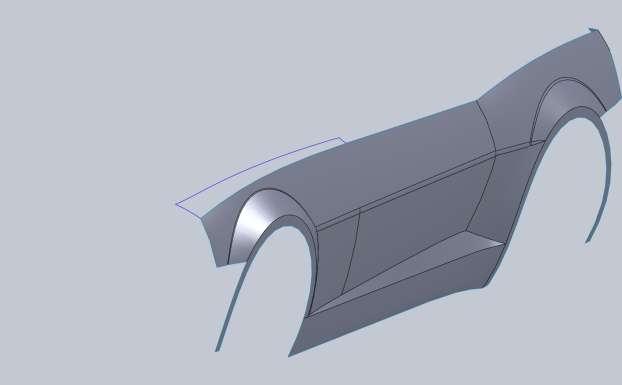
4 Since the Camaro is a new car you have the benefit of using the manufacturer s website. If you go to you can build your own Camaro. Inside here you can rotate the car 360degrees. This is a valuable asset when trying to figure out body lines and I recommend you do this when possible. When you plan out the approach to modeling this car you need to look at the hard lines of the body and find good places to break up your surfaces. The door and front fender keep the same bodylines but the rear fender flares out. So at a first glance I want to model the door and front fender first. Sometimes it s best to start with the roofline or the glass but I think the side of the body will give the most trouble so I want to tackle it first. Start a new sketch on the Right Plane and we are going to layout the top ridge of the fender/door. Start by drawing a spline from the front edge of the fender to the back edge of the door like below. Now use the spline handles to control the curve and match the shape of the body. I ended up with my handles like this.
5 Keep in mind when making these splines that the body lines on other parts like the front nose cone will end up with a tangent relation. Make sure your handles are reasonable in their direction to account for this. End the sketch and start a new sketch on the Top Plane. We want to draw the same body line we just did, only from the Top View. In some cases (such as this) I like to use Convert Entities on that first sketch onto the top plane and make it a construction line. The reason I do this is so I can add a horizontal relation. It helps me early on in the model to know my blueprints are in a reasonable spot and that my project curves will hit where I want them to. Again you only want to draw the start and end of your spline. Make them horizontal from the endpoints of your converted construction line and make sure they hit the same spot on the blueprint image as our original sketch.
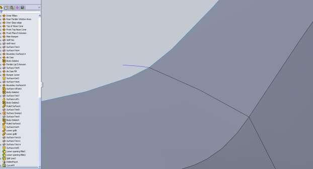
6 More important than exactly matching the line on the blueprint is ensuring that you have a nice stable spline. The blueprint images are pixilated and not exact in most cases. Use your judgment to know when a deviation from the blueprint is warranted. So far we can hit these curves by only using the endpoint handles. You will find this to be the case for most things. If you end up with 4 or more spline points you may want to take a step back and see if there is another way to approach the model. Now with our first two sketches we can make our first projected curve. This is the procedure that we will follow for the entire model with slight variations of course. Most notably will be how and where we add relations and what type of surfaces we will be creating with these curves. I have added the Curves button to my quick menu(s key on the keyboard). I find with models like that that I use it enough to warrant putting it there. You can find it on your Features tab or Surfaces tab under Curves. It s important to note the two differences in projection types for Projected Curves.

7 Sketch on Sketch will allow you to take two 2d sketches and create a 3d curve where they meet. Sketch on face will be used later possibly for things like sweep paths for window seals. This allows you to take a single 2d sketch and project it onto a 3d surface. Make sure you use Sketch on Sketch for now until otherwise noted. Select both sketches and create your first bodyline. Now for some reason these projected curves often aren t visible when a sketch blueprint is there so you may need to rotate the model or hide some of the blueprint sketches to see this curve. If you select the curve in the window or in the feature tree it should be easier to see. Also take this opportunity to rename Curve1 to something meaningful and notice that both 2d sketches are consumed by the Curve1 feature because they are children to it. Once we use this curve along with others to create a surface this will happen again. I named mine Fender Door Ridge. From here on out I will give you very general guidelines to help, but the point is to learn and not regurgitate. I won t be telling you to OK the sketch, it s just implied. If I use something new I will point it out but the procedure is the same from here on out for the majority of the body. The next curve will be the front edge of the fender. In a new sketch on the Right Plane I draw a vertical line. I select the end point of the line and the 3d curve from the previous step and add a coincident constraint. Here it s important to note the pierce constraint. An example of the pierce constraint would be drawing a 2d sketch where a 3d curve will intersect this sketch at some point. Pierce will make your sketch intersect this 3d curve. In this case our 2d sketch is on the Right plane while our curve never intersects this plane, so coincident must be used. Also you may notice if you select the endpoint of your 3d curve that you have no relation options. This is because the endpoint doesn t lie on the plane. However if you select the entire curve it will be projected but not actually drawn in your sketch. Make sure after you apply the coincident relation that you try to move your line all the way to the end of your curve. If you are not at the endpoint it will cause issues with your surfaces so this is important. Another thing you could do is use Convert Entities on your 3d curve or you can go back to the 2d curve on the right plane. This is possibly a more stable method because it allows you to pick an end point. This way if you go back and edit curves they will more than likely update better. I will let you make the call on how you do this because part of learning is finding out what works and what doesn t. It s a good idea to create a new part and play around with these projected curves and watch what happens when you make changes.

8 The second 2d sketch this time is on the front plane and not in the top plane. The reason for this is simply the direction of curvature of the model. If you look at this from the top it would be a straight line and you would not accurately mimic the curve. It will be up to you to decide which views to sketch in and it will take a bit of practice to pick up on this. Be prepared to do it wrong several times. Some compound curves may also require you to try a few different methods. There is nothing wrong with trial and error, so don t get frustrated if you have to get it wrong a few times. The first thing I do is create a 2point spline. Before I mess with the handles I apply a coincident relation between the endpoint of the spline and the 3d curve (either by selecting the curve and converting, then using it as a construction line, or simply applying it to the curve. Remember it s up to you to find out which works best. Making sure that both 2d sketches intersect the 3d curve at the same point will ensure your Projected Curve will be in the right spot. Go ahead and adjust the curvature to match the blueprint.

9 At this point you may be wondering why aren t we just using 3d sketches for this? Well 3d sketches are very hard to control and your model will show this. Using 2d sketches and projecting the curves will be a much more stable method for you to model something like this. The end result will but much nicer as well. The next curve will be the back edge of the door. This is a tough curve because you can t see it from the front view which is where the curve is most important. Start with the side view.
10 Again, and I won t always mention this; apply that coincident relation with the 3d curve so you know the end point is coincident. When you try to drag the spline to the end of your 3d curve the little coincident icon will appear, but if you don t convert the line, updates later may cause you problems, hint hint.
11 For the second sketch I m going to give the top view a shot since there is some curvature in this view. We will not be able to do this for the part of the door below centerline because it is hidden in the top view, but for this edge it should work just fine.

12 Select the 3d curve you create from these two and have a look at it compared to the blueprint. You may notice a problem. It looks great in my top view but in the side view it doesn t meet the bodyline where I wanted. This isn t good so we need to think on it a bit. Okay so it s time to make use of rolling back the feature tree. Below the bottom feature in your tree is a dark blue bar, you can grab that and drag it up the tree. Drag that blue line above the last 3d curve we just created.


13 Next we complete the 4 th 3d curve which will be done from the side and top views. Don t worry about the wheel arc just yet as we will trim the surface for that. If you try to create the surface with the arc already cut then it will produce some unwanted geometry. We are going to make this curve before the back edge of the door in our feature tree. This will let us go back and edit that back edge to meet the bodylines properly or maybe create a new 2d sketch on the front plane. Only time will tell. For the front edge of the fender go ahead and use Convert Entities and make it a construction line. Then apply a coincident constraint between a spline and its end point. At a first glance you may think this bodyline is straight but once you draw your spline you will have to edit the handles a little bit to match it. When you are drawing your top view curve don t worry about the wheel arch. Try to get the underlying geometry to line up.
14 Pay attention to the curves on the blue print, especially the nose cone lines. After you make this 3d curve (and name it), roll the end of part past the door back edge curve you created. Now notice how short it is of our body midline. So it looks like the top view we used for it just isn t going to work. What I did was delete the 3d curve for the back door edge and moved the sketches to the end. I also deleted my top view sketch that was used for the back edge of the door.

15 What we need to do is create a front view sketch that meets both our 3d curves and is as close to the body shape as we can make. My spline starts out like this with my relations added.

16 We know from looking at pictures and rotating the build your own model on the Chevy site that this door line appears to be close to the same arc as the front edge of the fender. Keep in mind you do not want your lower spline handle to be vertical; we still need a crisp body line. Once we make the surface (and the bottom part of the door) we can edit this spline if we feel it doesn t look right.

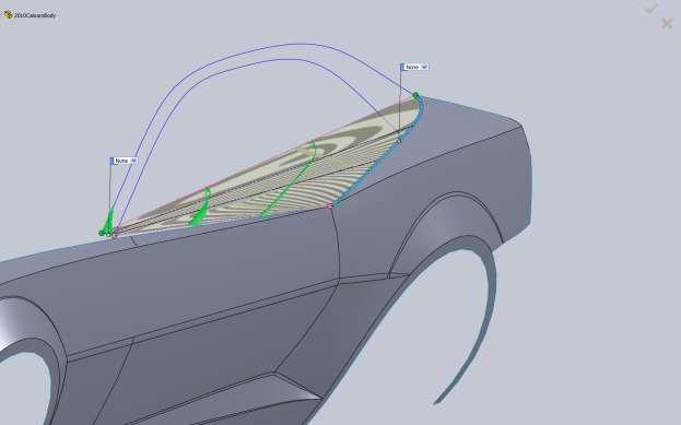
17 To make this projected sketch work out we need to go back in and edit our side view sketch to make sure that it is coincident with our door midline 3d curve. Then our new projected curve should look good. This is a very important part of the model, the first surface. This surface can be Lofted, Boundary or filled. And although it might seem like they would all be the same, each one may produce a different result. We don t have any other surfaces so we aren t worried about constraints with surrounding surfaces, but make use of the zebra striped previews in each surface to see any differences. Lofted, make note of the green handles on the loft profiles. You can manually move these from one side to the other. Each profile needs to have these on the same edge or the loft will try to twist.

18 Boundary surface And the big difference, Filled Surface.

19 If you rotate a filled surface around you will notice it will not work. The issue is that all 4 edges are curved in several directions. It makes it hard for filled surface to work. This would work well if we had a surface that we needed to trim and fill. Without the use of surrounding surfaces to apply tangent or curvature relations, filled surface is very unstable. For this surface I chose a Boundary Surface. Loft and Boundary surfaces will be nearly identical in this instance. The benefit comes in the needed curves to create the surface. Loft needs a start and end profile. Boundary can be created with two curves; one could be a guide similar to a sweep only your profile doesn t need to be 2d. Because the bottom half of the front fender shape is a little different than the door, we are going to go ahead and cut the wheel arch from the surface we just made so we can start filling it some more panels. When you draw the sketch to cutout the arch draw it large enough so we can also use it to cut the lower part of the fender later. There is no point to make the same sketch twice so we want to ensure we have enough to use later. Unfortunately it s not a simple arc, but a spline can fit this shape by just using its end handles.
20 A common mistake here would be to use multiple points to make the arc but this will yield bad results in your surfaces. Use the Trim Surface command to trim away the wheel arch from our surface. Also as another note, if your surface has blue edges like mine below, this means your 3d curves are visible. You want to be very careful when making surfaces that you select the edge of the surface and not the 3d curve. The 3d curve will not allow you to make use of tangent or curvature face constraints.


21 Another warning for you. It s much better to draw hard corners and come back to fillet them later rather than trying to model the filleted corner. This is why we are going to leave hard body lines and smooth them out later. Since we are going to model the rest of the door and the front fender in pieces, there is no point to having this a single surface (visually) so we can use the split tool. Create a 2d sketch for the door seam and use Split Line on the Curves drop down. Looking at the model I ve decide to take care of the upper half of the rear fender to ensure we have good bodylines to work off for the lower half. Even though it s good to setup a plan of attack, if part way through you see a better way to approach the model don t be afraid to take it. Save often and save copies if you want to try and model from different perspectives.
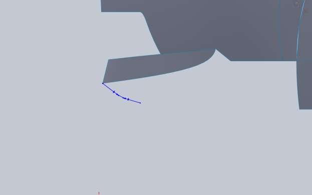
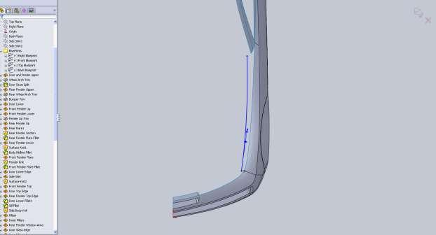
. Next is the Top down sketch. This is one of those rare splines that needed a 3 rd point.")
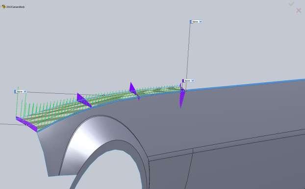
22 I start by modeling the upper edge just as we did for the first surface. I make sure it s coincident with the surface and tangent with the top edge of the surface. In order to follow the bodyline I have to make the handle really small (reducing its weight). Next is the Top down sketch. This is one of those rare splines that needed a 3 rd point. This is because the rear had a hard edge. I came close to getting it without the extra point but it was not a stable spline. Again the spline is coincident with the edge of the surface and tangent with the top edge.

23 Here is a front view of the surface and this new 3d curve.
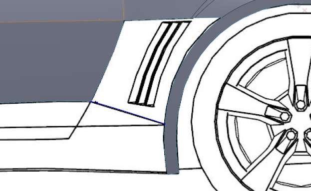
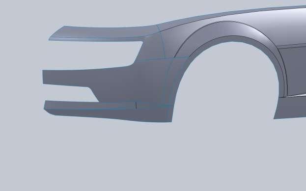
24 The procedure for the rear is similar to the front. We won t worry about the wheel cut out and also we are going to model more in the back and cut away for the tail light. Your surfaces will be higher quality if you can avoid surfacing in small areas on big panels like this. Here you can see how far I went past the bodyline. This is roughly where I think the back edge will continue to (will be clear in a moment).

25 Again on the top view carry the body line past the back.

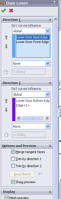
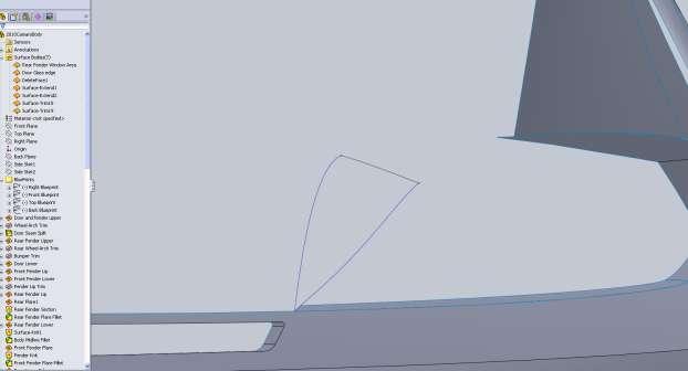
26 Now we don t need to fill in the back of this because we will use a boundary surface. Using the edge of the door surface as Directioin1 and the two 3d curves as Direction2 this should give us a nice rear fender surface. Under Dir1 you want to apply a tangency to face condition from the drop down box. We may need to go back and tweak the sketches a bit if we don t like how the rear turned out but we will cut out the wheel arch and tail light area first. Even though the rear wheel arch is only cut on the top (and not near the door), draw a larger section of the arc. Trim the surface, then go and draw a sketch to show the rear tail light area. This was a combination of some straight lines with fillets and a spline. The reason I filleted the cutout is because we don t want a hard edge for the cutout here. We are going to use this edge for the rear bumper and the sharp corner would produce a bad surface.


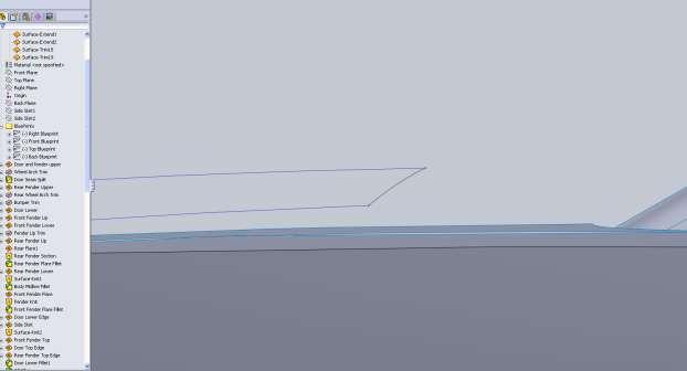
27 So here is where we are now. There is a problem that needs to be handled and it s a result of the boundary patch. It s better to catch this now. Roll the end of part up above the two trim operations so we can deal with this surface. Looking at the surface, the problem is my Top Down view of the lower edge of the surface
28 didn t go back far enough. Now when you project curves, some of the curve may not project if they aren t the same length. You can see from the image below, my top down sketch doesn t extend nearly as far back as my Side view sketch. My solution could either be to make sure it hits at the same point or extend it farther. I just extended it farther making sure the bodylines are kept.


29 Once you exit the sketch, your 3d curve should update as well as the surface created from it.
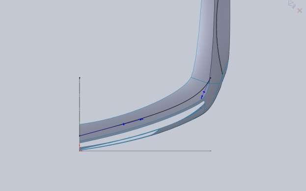
 to drive the shape of the fender, I didn t want any influence on the back corner.")
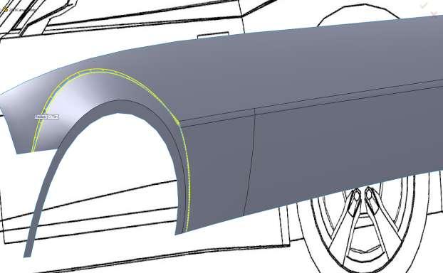
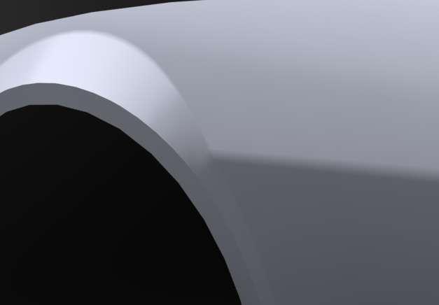
30 It s pretty close but still not perfect so a little more tweaking will help. I m going to tweak the side curve for the lower edge a bit farther back so our angle is better. This could have been handled by making a curve for the back edge, but because I wanted the front edge (door) to drive the shape of the fender, I didn t want any influence on the back corner. You can play around with these curves until you like the shape of the back corner. When you have it looking good, roll the end of part down below the two trim operations.

.")
31 I want to take this point to stop and show a view of the Feature Tree. Everything is named something that will help me identify the operation. I didn t name every sketch, but I labeled all the curves and features. You may also notice that the Surface Bodies folder says (2). Even though we split the door seam on the first surface, it is still a single surface. Later when we actually cut

32 a space for the door gap we will make these different surfaces but for now, the split was simply for reference. Now on to the rest of the door. Now here is where a little bit of educated guessing comes in. We can t see this edge from the top view or the front view. We will have to use the shape of the body and pictures to come up with this edge. In the front view I Convert Entities of the side view spline so I have the point at which it ends on the bottom (make it a construction line). Then I apply a horizontal relation between that and my spline.


33 Of course the other end is coincident with the edge on the door we are dealing with. You will have to do your best to get the shape but this may require us to come back and tweak it a bit if needed. Do the same thing with the back edge of the door.


34 I did the same thing in the front view with the horizontal relation. Also in light blue you can see the 3d curve created for the front of the door.

35 For the lower edge we know that the fender flares out and that its tangent with this door seam so I made the handle at this point with not much weight. I know that I will need to make my curve for the rear fender tangent to this 3d curve so I m planning ahead. Now since we have the front and back edge of the door in 3d, we can make a top down view for the other part of this 3d projected curve. This allows us to look at the body from the top down and pickup on any design cues. I ve decided to give this a little curve towards the rear of the door from looking at pictures of the car.
36 I ve decided again to use a boundary surface. Be sure that you use the edge of the existing surface and not your 3d curve. In the Direction box it will say Edge and not the name of a 3d curve.
37

38 Before we get too far on the door we should fill in some more of the fenders. It s important not to spend too much time getting into details just yet because some of the surfaces may need to be tweaked. Details like the fender flares will be important for how the fenders transition into the door and since the rocker panel is flush with the fender we need to be sure of all the major lines. The actual fender opening wasn t a perfect arc again so I used a spline. I added a vertical relation to both spline handles and then just pulled their weights until it lined up. I went ahead and offset this spline but made it a construction. Later we will convert that into another sketch and use it. It doesn t perfectly line up on the back edge but I d rather have a perfect offset than to pull that back edge in.


39 For the front I just made a large spline that followed the bodyline. Remember that some of this will get trimmed when we project the two sketches together.

40 In a new Right Plane sketch I convert the offset spline then make a projected curve from that and the same Front Plane spline used for the last projected curve. The result is two 3d curves that are in plane with each other. I can then use both curves for a boundary surface. Next I start to fill in the section of the fender between the door and the wheel flare. The one difference here is I make the sketch used to trim the fender visible and add a coincident relation between it and my spline, but not at its endpoint since it doesn t hit the body lines where we want.

41 In the top sketch I convert this spline and add my horizontal relation so I know where it ends. Then I flare it out about what I think it should do. Because we can t see this it s all guess work, but you can look at the bottom edge of the boundary surface we just created for reference.

42 For the next edge I convert the wheel arch trim sketch as well as the 3d curve we just created and the lower edge of the upper half of the fender, and then I use these to trim the wheel arch to what we want. I leave them in the model as construction lines but I could delete them if I wanted to.


43 Then from the front view we want it to be coincident with the lower edge 3d curve and the edge of the fender. Then we need to rough the arc out.

44 When we go to fill in the small area between this new curve and the fender lip we will end up trimming the bottom of the fender lip, but we won t worry about that just yet. Make a boundary patch and make sure you have a tangency to face constraint with the door edge.


45 Now we can make a sketch to trim the bottom edge of the fender lip. I drew a straight line, made it coincident with and tangent to the lower edge of the piece we just made.

46 If it doesn t cut all of your surface off (both corners), you may need to go back and alter something or else you will end up with some unwanted issues in a little bit. So what we are going to do is a boundary patch with a little twist. In the direction1 box you want to right click and go to Selection Manager. You are going to want Select Group which is the 3 mouse cursor icon. Then select the arc on the original surface we made and the arc on the new surface we just created then select the green check mark. Still in Direction1 we now want the edge of our fender lip.
.")
47 Now you might be thinking this looks a bit odd. Make sure you are on the Right View (Ctrl +4 on the keyboard if you wish). Now Left click and hold on the green down on the Fender lip and drag it up so it looks about right.

48 This is a great benefit when using boundary surfaces. If we wanted would could also add some directional constraints to bulk up the flare but for now just OK the surface and take a look at what you have. It looks pretty good but it s not really there. Edit the Boundary Surface and with your open group selected in the Direction1 box add a tangency to face constraint. Just as a note there are some dropdown boxes floating around in the graphics window with leaders to your selected edges. You can use these as well. That looks a little better to me, but there is one thing I would like to change. Where that lower piece of the fender is in relation to the fender lip. It like them a little closer so the flare we just made blends a little better. What I actually did was to make my endpoint for the Fender vertical to the lower edge of the fender lip.

49 If your model is close to mine this probably threw up some errors. I had to go back and ensure that my 2d sketches for the Arced edge of the fenders stayed coincident since I moved a line that it was connected to. I then had to go back into my Fender Flare boundary surface feature and reselect a few things. This is exactly why you want to make sure you take care of problems as they arise and don t get into too many detailed items until your surfaces are nice and stable. With only a small headache now the fender flare looks better and the area where the fender blends into the flare is nice. BUT, there is an issue we created here. Because the edge we used for our boundary surface, more importantly the tangency with face edge, has a sharp corner, it put a sharp corner into our flare. What we can do is go back and fillet that edge before the boundary surface. To see if this is a valid route roll the end of part line above the surface we just created. Now in order for us to fillet the edge, we need to knit the two surfaces together. BUT WAIT, this poses another problem. We have to knit both door pieces and the fender pieces together to be able to fillet. BUT WAIT AGAIN, yet another problem. If we knit all these together and fillet the edge to make a nicer flare, we will run into issues making the rest of the rear fender. Mainly because the filled edge would now need to be used but it doesn t line up with our rear fender edge. These are the types of problems that arise and why it pays to play around and look ahead in the model. Basically what we need to do is don t make the fender flare yet because of all the problems we would create by doing so. Roll the end of part marker back down and delete the Fender flare surface. The reason we don t just leave it suppressed is because once we fillet the edge of the fender, our selection will have changed and the surface wont update, so it doesn t save us any time to leave it there. Now

50 you might be thinking what a waste of time that just was, but don t forget that by making the flare, we saw that the lower edge of the fender needed to be pulled out a little in order for the flare to blend nicely. If we did not do this now, later in the model it may have caused a world of problems for us. So now we move onto the rear fender. In the blueprint image there is a hard line on the rear bumper, but on the actual car it s not there so I made the arch smooth. I ended up doing this with a spline with an extra spline point. In this case the straight section on the lower rear of the fender couldn t be made with only endpoints. I again offset this spline and made the offset a construction line to use later. From the Back you can see the hard bodyline again. I just use a single spline and didn t pay attention to the hard edge.


51 Same thing for this one, boundary patch between the two.

52 Now to be perfectly accurate these fender lips really wouldn t be created by projecting the line from the back. I think to be perfectly accurate you would have to create a swept surface then trim that surface with the Right Plane sketch, but for this model the fenders done this way are close enough. For the fender flare go ahead with another Boundary Surface (if you haven t noticed boundary surfaces are pretty powerful). This time you don t need the selection manager, but you will need to drag both ends of the edge on your fender lip. And make sure you don t use the tangent to face option with the main part of the fender. Taking another look at pictures of the car I think we will want to fillet the intersection rather than blend it with tangency. In order to make sure of the intersection points accurately go ahead and knit those 3 surfaces together. I also added a 2 fillet which will help the blend of the next panel (I think).

53 Next curve
54 From the top sketch I converted the previous sketch from above to add the horizontal relation. This ensures I hit the fender lip at the right spot when the coincident relation is added. So now we have an interesting situation which happens every now and then. We have two edges of surfaces that we can use completely, and one that we need only a partial. Because we have that 3d curve which we know hits the fender lip, this makes easy work for a boundary patch. For the upper edge with the fillet you will need to use the Selection Manager, but for the rest of the edges you will not. Remember that your directions matter but once you select that 3d curve you will be able to drag your fender lip edge end point up to it and have it snap in place. Don t forget to add a tangency to face with the door.


55 Making good progress but we have a long way to go still. Since we have a good portion of the door and fenders we can now knit them together for a fillet. Knit everything but the front fender lip. Then apply a 1 fillet to the midline of the body.
.")
56 Now we can concentrate on the Fender Flare on the front. In your boundary surface Direction1 box make sure you use the Selection Manager for the edges on the fender (3 in total). The second Dir1 does not need the selection manager but you will need to drag the Green end point to match up with the blueprint image.


57 Now if you remember back to the first time we did this, we had a line in our flare where the hard edge on the door midline was. Now that we have that filleted it gives us a nice smooth transition.

58 Just as a reminder we ended up with no tangency to face on the rear flare. Because I was still not sure I went ahead and made the front surface with a tangency to face relation and did a quick render. Looking at pictures of the car there is a harder body line like the rear flare so I think the decision to fillet the edge is a good one. So with the front boundary surface make sure there is no tangency. Here is the edge with no fillet and no tangency. It s closer to the actual car.

59 When you get to decisions like these make sure you explore your options before you proceed. Small changes to surfaces can have a big change in your model farther down the road. Go ahead and knit the surfaces together so we can play with the fillets. Now after a little trial/error it seems that the geometry won t let us put as large of a radius as we did on the rear. It s based on the surrounding geometry but that s okay. Looking at the model to figure out why it seems that the midline of the body is out a little past the fender lip so it s causing fillet issues. What we need to figure out is if this is really a problem for us in the geometry (i.e., we need to fix it), or if it will be okay. So it s time for another render.
60

61 You don t have to render to see these things. You can turn the visible edges off and use studio scenes in the modeling environment, but I personally prefer to leave the modeling environment a bit bland. I keep shadows and perspective off. My decision for this was to alter the fillet size on both the rear flare and this one. I ended up with a 1 fillet on the rear and a.25 fillet on the front. This gave me a result I was happy with. Depending on how all your curves line up and work out, your results will be different. Hopefully not by much, but that is part of the modeling process. You have to work at these panels in a reasonable manner and be prepared to back up and possibly delete some of your work in order to get things right. The end result will be worth it. I think now is a good time to fill in the rest of the door and the side skirt. After that we will move on to the upper edge of the fenders/door and then probably the roofline. This is one of those rare times when a 3d sketch is appropriate. The reason is that I believe this line is straight with no curvature. We have the endpoints in the model already and with both ends constrained, the straight line would be defined in a 3d sketch.

62 Once again I am going to use a boundary surface. The first Direction1 selection is the straight line we just drew. For the second Dir1 use the Selection manager and select all of the surface edges in order to fill this in. After seeing the surface I don t think the car body is made with a perfectly straight line. Back to the drawing board so to speak. Get rid of that surface and your 3d sketch and then take a look at some car pictures. It appears that after the door seam the rocker flares out. So we will need a side sketch and a top sketch projected to make our edge for the Boundary Surface. Note how long the handle is off the front fender below.

63 Just do your best to follow body line cues. After you make the projected curve and boundary surface you may be thinking, It doesn t look that different, this guys crazy. No it s not that different and the end result might look pretty much the same. These kinds of details are up to you to decide what needs to be done. Like I mentioned early, the fender lips aren t exactly right, and that s evident when you look at the top down view over the blueprint image, but I feel that some artistic license can go a long way as long as you do your part to make the body lines flow. A blueprint image in every case is just a guideline for you. Don t get hung up about following the lines exactly or your model will show your frustration. Now let s fill in the rest of the side skirt. This will also require you looking at a lot of pictures because this will not be visible on the blueprints. Here are some screen shots.

 visible and used that in")
64 Just another note for you. In order to match the curve of the fender, I made my original sketch for the fender lip (front view) visible and used that in my projected curve.
.")
65 This is why it s a good idea to draw your contours on certain things over length. This ensures that my curves will match the bodylines and it means I don t need to make another sketch. Another note for you if you haven t noticed yet. When you have a 3d curve in your model, and you are trying to add a coincident constraint, you need to select the curve (as mentioned earlier). When you are dealing with a surface, you can select end points.


66 Now with the two projected curves, the boundary surface can take shape.

67 It looks pretty good but I think the real cars side skirt rolls under the car a bit more. To achieve this we need to go back to the curves we used for the Fender Lips and alter their curves. Make sure you have saved the model recently. We will be going about half way up the feature tree and making and edit that has several things dependent on it. If you are interested you can right click on the Sketch in your feature tree and go to Parent/Child and see everything that is based off that sketch. We have to be careful how we modify these curves and remember what is dependent on them in the model. I pulled the bottom edge of the curve under the car a bit more and changed the arc. You also have to remember this curve has a direct relation to that fillet that gave us so much trouble on the front fender flare. If this curve gets moved to the left, our intersection with the fender lip will change and will probably throw up errors. Expect that you will get an error with the side skirt. This is because the front projected curve will have an intersection issue with the bottom edge. It s easy enough to fix though. After modification of the front curve and fixing the surface it s not looking like it will work out this way. What we are going to do is add 2 more sketches that will be used in the boundary surface definition. What I did was make two offset Planes from the Front plane. Mine were 25 and 55inches back. On these planes we will make splines that will control the shape of the rocker to have it roll under how we want. This will give us a chance to use the pierce relation. You will want to delete your boundary surface and make sure your projected curves are visible. It s also a good idea to drag the planes you created all the way up the feature tree. Since they are based off the Front plane and not any of our geometry there is no need for them to be in the feature tree. Draw a spline on your first offset plane and apply the Pierce relation between its endpoints, our lower projected curve and the edge of the door surface.
.")
68 Now this is going to be a tricky thing for us because we have nothing to make this curve tangent with. It s going to take a few tries to get this right (maybe). I start by making the bottom of the spline start to arc under a bit.


69 Do the same on the other offset plane then create a new boundary surface. What you will end up with is two edges for Dir1 and 4 in Direction2(or vice versa depending on your selection process).

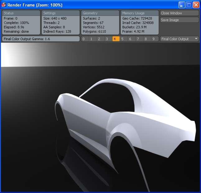
70 It s not bad but I want to add a bit more curvature to it. Just edit the two sketches just created and watch the surface update. One thing that may be happening to you is the surface gets really unstable in the center. This is because our extra two sketches are pretty close to the ends. So any major changes to curvature really mess with the shape. We can fix this by moving our offset planes away from the edges. I made mine 35 and 40. Really since they are so close we could just do with 1 if we wanted. Now the side skirt has a little bit more shape to it. Once we finish more of the model we will come back and add a rule surface to the bottom edge and roll it under the body a bit. This will finish off that edge, but for now is time to move away from this area. Just to be sure that shape is what I want; I do a quick render of the current model.
.")
71 I think it s looking pretty good so far. By this point you should be able to pick out which plane you need to draw your 2d sketches on in order to get the projected curves (or at least be able to use trial and error). So from here out I will just point you in the right direction for next part to model and show you some screen shots with any things to look out for. Next is the top edge of the front fender. I start with the front edge from side and front views.

72 If you remember way back we split the first surface at the door seam. Well when we knitted everything together that edge is gone now. Not really a problem because as you saw we don t need that reference edge. We can choose how much of our edges to use for surfacing. Just be sure that your curves actually are coincident with edges or other 3d curves or you will have problems. For the back edge I draw from the side view and the top view (because you can t see it from the front). Be extra careful with this one because we don t have an end point. Make sure you convert the side view sketch (as a construction line) and use a horizontal relation so you hit the top edge of the fender at the same point!! There may come a time when you need to hide some of your surface in order to see your blueprint. This is fine but I would make sure you apply your coincident relation first.
73
74 When you are making your boundary surface, I would suggest you selected your surface edge first and dragging the endpoint close to where it needs to be right away. Then continue with your other selections. Don t apply any tangencies. Later in the model when we finish the entire top edge we will fillet this sharp corner. The next piece is the top edge of the door that matches the fender piece. Looking at the blueprints and pictures it looks like this piece goes back to a point we only need to create one curve. For the top curve you may need to place your relations then hide the body that s obstructing the Top blueprint.

75 For the Boundary surface I select the small edge of the previous surface (top of the fender) as Direction1. Then for Direction2 I select our new 3d curve, then the top edge of the door. Notice that SW automatically shortens the edge selection since our Direction1 intersects it. You could have also knitted the surfaces together first but that would just add an extra step in the feature tree we don t need. Solidworks is pretty smart about this stuff. Don t forget to add your tangency to face relation with the top edge of the fender (your direction1 selection). Now you should have the top edge of the door and fender.

76 I am going to continue with this ridge by finishing the top edge of the rear fender. From the side view this is nearly identical to the current body line so I start with the top view. Near the rear glass where the C-pillar meets the panel we are drawing there is a hard edge. Don t worry about this for now and just blend your spline as if that edge wasn t there. If you try to match that edge, your panel will have a wrinkle so later we can trim the surface if needed. Also I made my spline tangent with the top edge of the door and not the edge of the surface we just drew. This is a judgment call on how I think the body lines will lay. Hopefully I am right.
77

78 For the side sketch I make it coincident with the point on the door but I don t apply a tangent relation. I thought about it, but I don t think this edge will match up with any bodylines so I just try to make sure it s barely above the fender line and that at the door it stays above the fender line.

79 The reason is because I think if it dips below the fender line it will mess up our fillets. This is all guess work (educated guess work), but it may or may not work out. After you create your 3d curve make sure to look at it to ensure it travels all the way to the point you want. The reason I caution you on this is because our side view sketch didn t really have any reference. I could have converted my top down sketch but I didn t. No real reason. As I am drawing my top down view I make a note of the back section of the fender near the taillights. From the side view this looks great, but from the top view you see we will need to add a bit of material. No problems here I just wanted to point it out. I apply a tangent relation to the back edge of my surface and my spline.

80 Make sure you give the side view sketch a little arc and keep it above the fender line.

81 It is really hard to tell from the blueprint where things are supposed to be so just use your best judgment. You can see the major bodyline so try to roughly match that. When making the boundary surface we have nothing to apply a tangency relation to. Make sure the shape of your panel is acceptable. To make sure we are on the right track it s time to knit all these pieces together and try to fillet the top edge. I already know this will cause a problem where they all meet at a single point but I have a way around it. I am going to use a Variable Fillet. I start with the rear fender and I apply a variable fillet that is 0.25 at the rear and 0 at the intersection point. For the front I do the same thing with 0 at the intersection and.25 at the front edge. Since the front edge has a break in it we will have to give it 3 values. At the front it will be 0.25, at the door seam it will be and at the intersection point it will be 0.

82 While I am doing this I realized I forgot to fillet the triangle cut away in the door so I apply variable fillets there as well. At the start and end points I make it 0. At the door seams front and rear I make it For the rocker edge I follow the same procedure except I use the 50% point at give it a radius and make the start/end 0.

83 On the real car these would be a much different story. Since we don t have great references for how all the panels meet and lineup with each other we just have to wing it. To make sure we are on the right path and we don t need to make the fillets larger I do a quick render.
84 It s not bad but I decided to try a larger fillet. I made all the fillets on the lower part of the door I also make the top ridge start at 0.5, door seam 0.25 and the rear of the car 0.5. It s not a huge different but I like it a little better so those are the values I am sticking with.

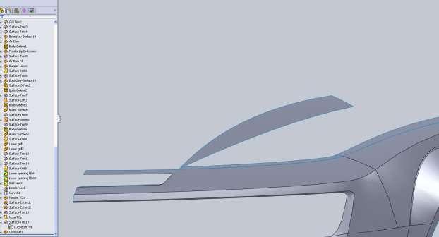
85 We can leave the fillets for the lower part of the door, but we need to remove the fillets from the top edge of the fender so we can continue the model. We don t want the fillets to influence the shape of the nose cone or trunk. Once the entire top portion of the body is modeled we can apply these fillets. If for some reason these edges didn t fillet this would be the time to fix them. At this point in the model there are some smaller surfaces around the door windows but for now I am going to work on the roofline a bit and the surface that makes up the A and C pillars. I made my top down spline coincident with the rear fender but I did not pull it all the way to the end point. Looking at pictures it appears that there is a narrow surface area there that gets blended into the Pillar surface. This is another one of those small details that you could take it or leave it. I think it will help me later to create the surfaces this way.
86 For the side view I convert my top sketch as a construction line so I can apply vertical relations with the end points and make sure they hit the rear fender at the correct spot for us. I ended up with a 3 point spline in order to create the roofline.

87 The extra point was placed in the middle of the roof. You can see the 3d curve created does not contact any part of the front fender. Next we draw part of the A-pillar. We are going to make this side in a few steps. It is important from the top view that you make sure you handle is tangent (visually) to the hood line because when we draw the hood we will be using this top view of the surface we create for our tangency.

88 From the side view you have to use a little imagination. We are going to want a little bit of curvature and this will eventually end up tangent to the door edge in the next surface. Keep this in mind as you draw this curve.

89 For the next curve I want to be sure the A-pillar portion matches so I am going to offset the edge from our 3d curve and do some trim work. A 0.50 offset worked for me.

90 I hid the blueprint so you could see this. The black curve is my offset of the 3d curve. The blue spline is one I added, then used to trim the offset. After I trimmed the offset, I applied a tangent relation. There is another part that needs some attention. That is where this offset curve hits our 3d curve for the lower part of the A-pillar.

91 In order to get this to work out, select the black offset curve. In the properties window in the feature tree you will see Existing Relations. Delete the Offset Entities relation. Your spline will now be blue. Apply a coincident relation between its end point and the 3D A-pillar curve.

92 The reason I went through all this trouble is because I wanted the curvature of this edge to match that of the original 3d curve. If it doesn t match we will notice it in the final model. Make sure you trim and work with the back edge and get that how you want before you delete the Offset relation or you will end up modifying the curvature and we don t want to do that. We have to follow a similar procedure for the side view sketch. In addition a convert the top down sketch in order to make sure I hit the rear fender at the same spot. From the side view our Offset isn t nearly as close so we will end up trimming away a lot of it.

93 I had to add a 3 rd point to my spline in order to get the curvature correct. You will also notice that the spline doesn t hit the right spot on the rear fender. I think its close enough since the line between these two surfaces will not be critical. If you want it closer you can go back to your top down sketch and tweak its position until you find a suitable medium.

94 Don t forget to fix the area to the left where the offset curve needs to be modified to meet our other 3d curve.

95 Now we have something that looks about like this. For your boundary surface you want to start with the small curve and rear fender edge for direction1. When you select the other two curves for direction2 the endpoints should automatically adjust themselves. Early in the document I had you manually move things around. This was mostly to show you that it could be done. When you have these guide curves that intersect, it should not be necessary.
96

97 Take a good look at this surface and you will notice some problems. What is happening is the surface is starting to roll itself, but we don t want that. The real car has a nice hard defined surface here. This happens in my model because a closer look at both of my curves and I can see they don t really match. Where it gets narrow at the beginning of the roof is where my problems are coming from. Your model may be fine depending on your curve, but it may not. I am going to play with my right sketch to see if I can get things in better shape. My curve was close to that in the blueprint but it just didn t work in the model. I basically started over again. Deleted my 3 rd point on my spline and got rid of the original offset curve. Here is my new curve.

98 Because I completely redid the curve my surface may not update so it will need to be re-done. My new surface is better but still not acceptable to me. I think what I need to do is add a few cross curves to help drive the shape. Similar to what we did with the side skirt. I went ahead and deleted the boundary surface, started a sketch on my second side skirt offset plane, pierced both upper and lower curves and gave my spline a small amount of curvature.


99 I am hoping since this curve is right where the problem starts, its influence will carry through the surface.

100 I am now happy with this edge and can move on to the next piece. Again to make sure things look right I am going to offset to get my curve. It will not exactly match the blueprint because of the tweaks I had to make but it will be close. One thing to note is back here.


101 Even though this is one surface around the window I am breaking it up into two different ones. When the next one is created we must use the tangent to face relation to make it look right in the renders.

102 For the top sketch for the rest of the A-pillar I make it tangent to both the top edge of the door and the surface we just created. It is the same thing with the side view sketch.

103 For this boundary surface I am going to make this surface tangent to the one we just created and see how the renders look. It will be difficult to put a hard edge here and fillet it because of how it meets the rear fender. If the tangency doesn t look right we will end up with a variable fillet with start/end radius equal to 0. After the surface is created I already notice a problem. Instead of either a nice tangency or an external edge we now have a dimple in the pillar.

104 This means that we need to either push the inside edge in or pull the other edge out. I am going to try pushing the inner edge in by modifying my top sketch. I changed my 0.5 offset to 0.25, and altered the C-pillar curve.
105 This is much closer, but before I make the final decision I change the surface to have no tangency and see what the render looks like. With Tangency:
106

107 With No Tangency:

108 I am still not sold on it. I am going to push the upper edge out a little and see how it looks.

109 I think this looks the best so far. Because your curves will all be different than mine you will have to play around with them and get something that looks reasonable to you. In the end I tweaked everything 4 or 5 times and ended up with tangency between the two.

110 Alright just one more piece around the window for now and then we move on to either the front end or rear end. Since there is a hard point where the door meets the rear fender I am going to break this piece up into 2. I think it will end up better that way (hopefully).

111 From the top view make sure you have that spline a little bit of an arc to roughly match the edge of the fender.

112 When filling in the front edge of this piece make sure you add a tangent relation with the door edge. If not it will look odd when we make our surface. Same thing from the top.


113 Remember to add the tangency during the boundary surface creation. For the side sketch for the front part of this surface I make it tangent to the top edge of this surface.

114 Again, from the top view convert your side sketch so you can apply horizontal relations and make sure they hit the A-pillar at the right spot.

115 You always have to be conscience of your 2d sketches and how they will be projected into 3d. You have to make sure the end points of your 3d curves hit endpoints or edges of surfaces or other curves in order for all your surfaces to work. Note the tangency with the blue surface. After looking at the model I decided to remove this tangency. Because there will be a door gap there it shouldn t stand out in renders. Adding the tangency created some unwanted ripples. I think the model is coming along nicely and now we can get to the fun parts that really help define the car.

116 I am going to start with the top part of the nose cone. This will help us define the hood and the rest of the bumper. The reason I don t work on the lower part of the bumper is because the upper part of the hose cone influences the shape of it so I would like to have that in the model. Normally when we are dealing with the part of a model that will meet its mirrored half we want to be sure that we use horizontal or vertical relations on our splines so we don t have a point or edge in our surface. Because the Camaro comes to a pretty hard point this isn t an issue for us.

117 Since we are sketching up to the center of the model we can convert our side sketches and apply coincident relations between them. Since the images don t line up perfectly don t worry about your curves being offset a little bit.


118 Always make sure you add tangency relations to edges where necessary. If you did everything right you should have a nice edge to start the nose cone.

119 With this car there is an intake hole in the nose cone. Don t worry about that because we will trim it away from the surface. Also the cowl hood lines roll onto the nose cone. We are going to approach that in a little bit but for now we have to do a little guess work. We are going to draw the hood line as if the cowl hood lines didn t carry over. These lines are a little more clear from the top view.
120 Since we are drawing up to the Right Plane we will not need to project some of our sketches. You can draw the profile of the nose on the Right Plane. Because our 3d curves actually hit the Right Plane, the pierce relation will work.

121 When you go to create your boundary surface I need to make one note for you. For you to select the 2d sketch you will need to use the Selection Manager and use the Open Loop option. Select Group that we normally use will not work. Don t forget to add tangency with the edge on the front fender. For the area of the grill we are going to draw as if the grill was solid, and then cut it away just like with the vent (which we still need to cut into the nose cone). It would be too difficult to try and patch the nose cone together with the grill opening in it.
122


123 So I have it for a reference I am going to cut the grill opening from this surface. I used two straight lines and filleted their intersection 0.125


124 Trim Surface and keep what you want. Note that in the above image I hid the surface so I could see the blueprint.

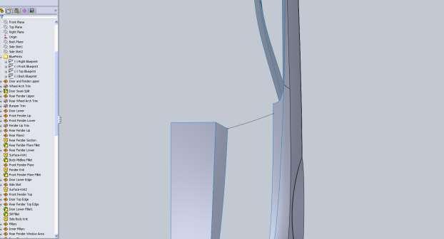
125 The nose of the Camaro has an interesting feature that makes do a little fancy work. The lower area of the bumper kicks out a little to simulate the old Rally Sport air dam. This pops out of what I would consider a normal bumper shape. So what we need to do is model the bumper without this feature, then we will trim and add this back in. I start by drawing the right side profile of the front of the bumper. I use the bottom edge of our fender lip to add a horizontal relation with the bottom of my spline. On a new right sketch I draw the upper edge.

126 For the top I project the sketch I just drew so I have a point to make it coincident with. Then add the appropriate coincident and tangent constraints and tweak the curve.


127 With that projected into 3d we not have almost everything.


128 We can t see this edge from the top so I have to guess a bit. If we drew this from the front our projected curve would have no shape to it.

129 Now with that projected we have all we need, but this is a big panel and has lots of different influences from other surfaces. This will take a bit of playing around with to get right. I start by going from the 2d sketch out to the fender lip.
130 Then for direction2 I add the bottom 3d curve, then using selection manager try to select the edge of the fender and our upper 3d curve, but it doesn t work!!!! That s unfortunate but a good lesson. There is a limitation in the selection process. So with this problem we have to think a little bit about what we can do. We can either build a surface based on the surfaces we have, and then fill in the rest, or we can go back and remove the grill trim we did and build the whole front surface that way. Before I back up that far I want to give something a try real quick. I made a boundary patch using the edge of my fender and the bottom 3d curve as Dir1, and my fender lip edge as Dir2. I only used part of the bottom 3d curve, and I applied a tangency to the fender edge. Thos could potentially cause an issue in the grill surround area. Looking at a render there is some wrinkle issues.

131 I don t like this at all, but looking at the front fender lip there is some work that I want to do. For now I am going to delete a few things. I got rid of all curves and sketches for this bottom part of the nose. I also undid my knit surface and rolled back the End of Part above my grill trim.


132 What I am going to do now is carry the fender flare down how it is supposed to look on the real car.

133 The dashed line is the bottom edge of the fender lip. From the right plane I just draw a horizontal line that is coincident with the fender lip. Project those together to get this:


134 Then create a boundary surface. I played around with using 3 edges of the fender.
135 And with just the flare and fillet edge.

136 I like this one better. Then I went back and altered the nose cone part we had already drawn by extending it out farther so we can have a smooth transition to the rest of the bumper.


137 Then I drew the profile. I made the bottom end point horizontal with the fender flare bottom. I also made the spline tangent with the nose cone we just extended.


138 I make the top view tangent with the bottom of our flare extension.


139 So now you should have the perimeter to fill in the main body of the bumper. Boundary surface with tangency to the top edge of the nose cone


140 I went back in and modified my grill trim sketch so I could trim both parts of the bumper.

141 I am also going to cut out some of the lower grill. The sketch goes past the grill because the bumper lip is going to be the bottom of the grill opening. Then I am going to try my hand at trimming away some of the bumper and start modeling the lip.


142 The cut line that goes down and to the right is just a guess. I m hoping to blend the bumper and lip together, but I wanted a hard corner so I had a place for my sketches to coincide with.

143 I start with a side sketch. From the front I convert my side sketch and try to match the curve of the front blueprint.
144 To finish off this lip properly we have to do a little extra work. I am going to have to fill in my bumper cutout and after I m done with the edges I will use delete face. From the side I draw the top edge continuation of the bumper. Same thing from the top.


145 The only reason I am doing this is so I will have a surface edge for my selection. As you can see from my boundary patch, I didn t even make it complete.
, but allow everything before that in the feature tree to still use this surface. This is a bit of a work around to get the air dam but it works.")
146 To get rid of the surface that s filling the bumper opening Right Click on its name in your Surface Bodies folder in the Feature Tree. You will see Delete Body. This will allow you to delete a surface (or solid), but allow everything before that in the feature tree to still use this surface. This is a bit of a work around to get the air dam but it works. Since I wasn t using any face tangency I could have started a 3d sketch and converted the bottom edge of the bumper surface I wanted to use, but I didn t think that method was as clean.

147 Next I think I am going to finish off the lower portion of the fender lip, then work my way forward.


148 All I need is the one edge. I am going to use the edge of the fender lip as Dir1 and the new curve as Dir2.

149 This part of the car is really where it pays to look at pictures. The blueprints aren t really helpful in determining the shape of the nose in this area. I am going to give something a shot and just see how the shape turns out. I start by trimming some more of the bumper to get rid of the hard edge. Then I start fill in a small patch panel. The spline shown is tangent with the bottom edge of the air dam. From the top I do the same thing.


150 This gives me a projected edge that will hopefully make it easier to blend these pieces together.

151 I think this will work out nicely looking at a quick render.
152 Looking at pictures of a lot of different cars I can t find one with the same bumper as the blueprint so I am going to make a slight change starting with this.

153
154

155 I think it looks a little closer to some of the images on the Chevy site. Without a reference photo that relates to the blueprint image, it s hard to figure out what it was supposed to look like. This is another one of those artistic license things. Nobody is going to see the model and think it s not a Camaro. At this point I knitted everything together except the A pillar surface. We still have a lot of roof work to do so I want to keep these separate for now. I am going to fill in some of the grill area then move onto the hood. While we are here lets go ahead and cut away the air inlet on the nose cone. Now what you want to do is offset your upper nose line and then your grill opening line.

156 Trim what I didn t want and added some fillets.

157 To fill in some of the grill area there are several ways we could do this. We could use a rule surface but they can get messy when you are dealing with surfaces with lots of shape. What I am going to is create a curve that we can use for a boundary surface based on an offset surface. Now earlier in the model we could have knitted the upper and lower part of the bumper together before we trimmed for the grill and made an offset surface. Since we have done several things it would be a bad idea to go back and try to do this unless you really want to see what happens. What I am going to do is create a 2d curve then fill in the grill opening, create an offset surface from that and trim it with a 2d sketch on the front plane.


158 I use a boundary surface. Direction1 selections are the 2d sketch and the straight line on the fender.

159 Direction2 are the top and bottom edges of the opening including the rounded corners. Make the top edge Tangent and all the rest with no tangency. This surface isn t perfect but for what we need, it will work just fine. Offset it into the grill opening then use the Delete Body feature on the surface that we filled the grill opening with. Now we can make a sketch on the front plane to trim this surface where we want for the edges we need. What I did was offset the bottom edge of the opening 0.5 and then manually drew the rest of it. I made my spline coincident with the edge just before the fillet on the offset surface.
 in the surface.")

160 You can see some bad geometry (wrinkle) in the surface. Next I convert the Top edge of the offset surface, and then add a fillet between that and my spline.
161 I changed the color of the offset surface so you can see what we are working with. Our boundary surface will go from the grill opening to the edge of the offset surface. Then we will delete the offset surface. I decided to use a Lofted Surface for this since I think it will give a better surface. Follow the same procedure. Use the selection manager and select the entire edge of the grill opening and then the edge of the offset surface.


162 The next surface we need to add can be a ruled surface since it will go straight back. For your Type you will want Perpendicular to Vector. Your Vector selection should be the Top Plane. I made mine 2 back because we are going to trim it.

163 This surface will cross over the Right plane so we will need to trim it with that first. In the Trim Surface trim tool selection, select your Right Plane. Next we can draw our trim line on the Top Plane. To make it easier I hid the majority of my surfaces. We are going to have to sweep this surface in order to get it right. To sweep this your path will need to intersect your sketch.
164 Don t worry too much about the sketches at the moment, after you sweep the surface we will need to tweak them to get them right. You can see mine just barely hit the surface.
165 After a little tweaking of both sketches I think its good.

166 Trim your rule surface with this then use the Delete Body to get rid of the swept surface. Go ahead and make a rule surface using the same procedure for the air inlet in the nose cone. Use the same type and Top plane. Before we move on to the rest of the fender and hood let s go ahead and finish the lower grill opening surfaces as well. If you look at pictures you will notice that the upper portion and side roll in a bit. I am
167 not going to exactly mimic this but I am going to use a Tapered to Vector rule surface for part of it, then fillet. Start with a Tapered to Vector rule surface using the Front Plane as the reference vector, and 30degrees as the angle. Next create a Perpendicular to Vector rule surface for the bottom edge using the Top Plane as the reference vector.
168 Now before we do any more let s use the Trim Surface function. Use the newly created rule surface to trim the previous rule surface. Then follow the same procedure using the first rule surface to trim the second. We are making the ends of these two surfaces meet. Now knit both surfaces together with the bumper and then apply a fillet to the edges shown. I used a fillet.


169 The reason we don t fillet all the edges is because we want the bumper opening to roll in. If we apply a fillet to all edges it will produce different corner geometry. Next I added a radius to the bottom edge. Under the fillet options drop down I check Round Corners. This helps blend the fillet better.


170 There is one thing that bothers me about this opening. Our first rule surface was 0.25 in length but it was tapered at an angle. Our second rule surface was the same length but it was straight back. Looking at the model, the second surface goes farther back. This isn t a huge deal but later on when we make the grill it would have to be addressed. I d rather take care of it now while the surfaces are fresh in the feature tree. On a top plane sketch I convert the back edge of the lower surface, and the vertical edge where we want this surface to hit.


171 In the sketch I want to leave both converted edges there and offset the longer edge. The distance doesn t matter because we will delete all relations with it. You will notice after you delete the relations that the edge is still black. If we just were to delete the relation for the converted edge it would be completely un-defined. Now you can use the Move Entities button and move the offset curve. Now the Trim Surface option may get messy here because all of our surfaces are knitted together so we have a few options. We could make a split line on the face, then Delete Face. Instead I drag my sketch up the feature tree and drop it just after my Surface-Trim operations. Now I can drag the end of part line up behind this sketch and trim my surface without worries. That should make the back opening of our surfaces meet at the same spot.


172 If you take a look at the model from the front view you will notice all of our rule surfaces overlap the Right Plane. This will cause issues later when we mirror the surface. You can see this best from the top plane. Here I made a sketch that s just a vertical line through the origin. I will use this to clean up these edges. It s a round-about way to trim the surface but because the surface is now so large, using trim would produce some issue. I use this line as a split line on all the offending surfaces. After you have split lines on the surfaces you can use Delete Face to remove them.


173 Okay now it s time to move on to the top edge of the fender and make the hood. From the top view you can see we have a little piece of the fender and nose left. The next set of images will show you the order in which I made the curves.


174 Not from the front view that my spline is not tangent with the nose cone line, but I have added a small amount of curvature.
175


176 For the back edge we run into the same problem we had on the grill area where we need to use an edge and a curve. For this one since we will have no tangency with the A pillar I am going to create a 3d curve to use. I make my projected curve first.


177 I notice from my side view that my hood line is a little lower than I want so I m going to edit it.

178 Now we aren t going to use this curve, but I want it for a reference. For your boundary surface select the small curve at the front edge for Dir1. Select the top edge of the fender and our longer projected curve. After the surface is created we will trim it to fit the A pillar.
179 To trim the surface hide your projected curve that we didn t use, but make the top view 2d sketch visible because we are going to convert it into another sketch. In this new top sketch you also want to convert the edges of the A pillar. If you look at the surface you will see there is a gap at the A pillar. We can use Extend Surface to fill that.

180 Since our A pillar parts aren t knitted together you will have to do this twice. Use Extend Surface. For End condition you want Up to surface. It looks much better but now the projected edge we used to trim our surface isn t in the right spot. I just delete the trim from our feature tree and start a new top sketch. Small details like these are the things that make your job that much harder later in the model if you skip them. Take the time to ensure the little details are acceptable when you come across them.

181 Next surface will fill in the top edge of the nose.


182 Note that the front curve does not coincide with the surface just above the nose.


183 For the right view I give it just a little bit of curvature.


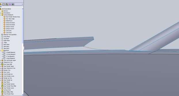
184 For the hood if you remember way back I mentioned how the cowl on the hood blends into the nose cone. To start this we are going to trim the surface we just made. I drew the entire spline so I would have it for my projected curve, but I am going to use it for the trim first.


185 From the side this gives us a nice point to make our spline coincident with. I also apply a tangent relation with the trimmed edge. This is a hunch that I hope works. I also add a coincident relation between the other point on this trimmed edge. The hope is that our cowl hood matches this edge.
186
187


188 Note that from the top view you need to add a horizontal relation to the handle that intersects the Right Plane sketch. This is so you don t have a hard edge on the back of the cowl when we mirror the body. We do not want that from the front view because the car has a hard ridge on the hood.


189 When making your surface make sure the front edge of your cowl has a tangency with the nose surface. This will make sure it blends nicely.
190


191 At this point I knit the hood and the skinny edge together (all shown in blue). This is for filleting reasons. We still need to draw the panel for the back edge of the hood at the windshield. We can see from the top view the trim at the A pillar is totally wrong. I need to go back and fix that so we can have a tangency here.
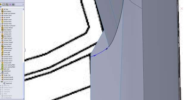
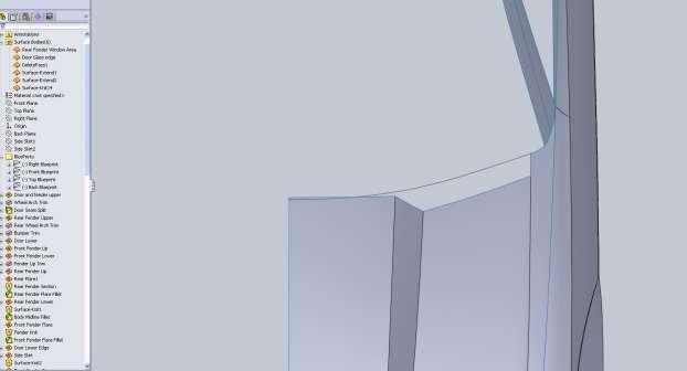
192


193 Remember that any curve that intersects the mid plane of the body needs a horizontal relation if you do not want an edge there. This means all the curves that define the edge of the windshield. I use my projected curve and the edge of the fender to create a boundary surface. After seeing this panel I realize that I don t like the shape of the last hood panel we made so I am going to back up a little bit. I re-do the projected curve for the back edge of the hood by rolling back my feature tree and adding a front curve as opposed to the side curve I used previously.


194 After modifying my curves my hood now lines up roughly with the panel we are working on. For this cowl vent panel I convert the hood edge and finish off the curve from the top. I did the same thing from the front view.


195 Just to make sure all the work done to keep a body ridge in the middle was done right I mirror the body and do a quick render.
196 It s very important that the body lines work well together so every now and then its good to mirror things but you want to make sure you don t work like that. You want to stick to half of the body as long as you can. It s a good idea before we move away from the front end to fillet the hood and the rest of the openings if we need to. I added a radius to both edges for the main grill opening.


197 For the air inlet I use a few different radii using the variable fillet option. This is because the angle of the angle greatly changes so the bottom starts at and the top ends at My six numbers go like this: 0.125, 0.125, 0.08, , 0.035, For the cowl hood I use a variable fillet for the top edge going from 1 at the back to 0 at the front.
198 Same values for the bottom edge. There is a small section up front that I leave 0 as well.


199 For the back of the car I am going to draw it without the spoiler and maybe add it back on later. From the back view:


200 Always remember when you need to use tangency and with what curves. If you don t the renders will show it! Since this is another one of those large pieces that has some intricate geometry we have to break it up a bit. I am going to use my C pillar lines to finish off the trunk even though there is no body line there. When I make the next panel I will make sure it has tangency with this face.
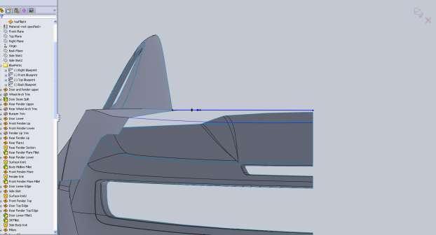
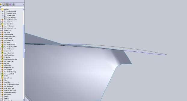
201


202 If you remember earlier when we made the back corner of the rear fender I mentioned the edge wasn t correct from the back view. At this point I don t think we need to do anything about it.


203 You can see from the side view there is a little extra overhang on my model. I m not worried about it though.
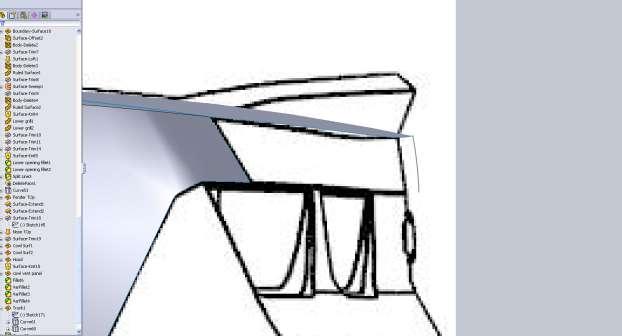
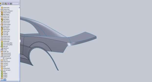
204
205 If you take a good look at pictures of the car there is a hard line on the back of the bumper that is not in the blueprint images. Little difference like this can make a big difference on the finished product. The next step is to create the rear bumper shape so we can trim some away and add in these details. There is a tough bit of geometry here because of the fender flare. I haven t seen any great pictures of this area so I just kind of let the surface blend itself. If I like the end result I won t worry about it. I start with a 2d sketch on the Right Plane. In this sketch I include the entire profile of the bumper, but I make the other two curves references that will be used for creating our projected curves. A nice thing about doing it this way is that if any modifications need to be made, you can go back to one sketch (for the side view). Next I start a new sketch on the Right Plane and convert the lower curve.
206 From the top view I rough out the shape. After you create your surface you may decide you want to tweak these curves.
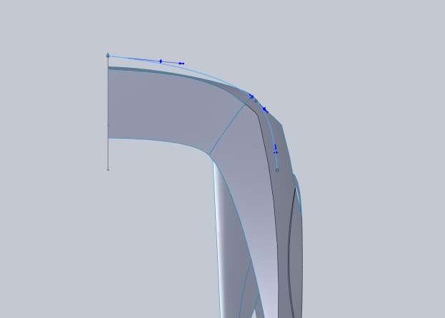
207

208 The next step is a small departure from the normal procedure for me. I start a 3d sketch and convert the surface edges from my rear fender. Then I create a spline that is tangent to this edge and intersects my first 2d sketch. The reason I did it this way was because of the need to have both the surface edge and a new curve as a guide rail. I avoid this whenever I can, but every now and then it seems that I have to do this. A way around this would have been not to cut out the tail light section but if you remember that was one of our very early surfaces. The only way (in my case) to avoid this was to have drawn the car first and figured out these little problem areas.

209 I use a Lofted surface for the bumper lofting from the fender lip to our first 2d sketch.

210 Next I trim the lower portion out from the back view. If you have noticed I am not putting screen shots with the blueprint images in here anymore. You can follow the blueprint images on your own. At this point it s simply just too hard to see these sketches with all the surfaces and images in a screen shot. I still use them until the end of the model.

211 The next thing I trim is approximately where I think this feature I want to add is. My vertical line is coincident with the edge of the rear fender surface.

212 On the Right Plane I now draw where I want the new profile of the bumper to hit.

213 This is used for a loft surface from our recently trimmed edge to this curve. You want this loft to be tangent to the surface of the bumper, and you want to make sure that at the Right Plane you do not have a any relations that will remove our nice ridge/seam from the middle of the car.

214 Now trim a portion off of the bottom of the new surface. Since we don t have a blueprint reference for this you will have to guess at it (if you even want this feature in your model).

215 Just be sure that you have enough room for your license plate cutout. A simple lofted surface between the two edges to fill part of the gap. You want the surface tangent to the upper edge but you want it to pull in at the bottom edge. You do this by changing the weight (called the tangent length) in your Start/End options section of the loft dialog. If you notice I did not use all of the upper edge. This is because we will need a small section to blend all these together.
216 So I trim a small section out of the edge.

217 I give this boundary surface tangency to every face except the bottom edge. It will not work with the surrounding geometry if we apply a tangency to this edge.
218 You should now have this nice lip feature on the bumper that blends itself in.

219 Knit all of these bumper surfaces together so we can make some room for the license plate. I start with a trim from the Right Plane.
220 I tried to follow the curvature of the bumper but this is going to cause issues when we look at the model from the back.

221 So we make another trim, from the rear this time, using the lower corner as a coincident point for a vertical line.
222 In order to make some details for a surface to fill this area I create a plane offset from the Top Plane by selecting a point on our lower edge.

223 In a 2d sketch on this new plane I draw a horizontal line from the lower corner of this opening to the center of our model.

224 Then use that for a boundary surface.

225 Do the same thing for the top creating a new plane and a 2d sketch.

226 Now you can use the available 3 edges to create a boundary surface for the tag area and knit them to the bumper.

227 The next part will be a little more difficult than the bumper area. We need to fill in the area around the tail lights. The reason I say it will be more difficult is because we are going to meet up with a few different surfaces all with different curvature so we need to be careful. I start with a 2d sketch on the Right Plane.

228 Note that it doesn t intersect the bumper. It s above it and slightly in front of it (to the left).

229 Next is a top sketch trying to follow the curves of the bumper the best you can.

230 I started by filling the entire area here but because of the fillet corners from our very early trim on the rear fender, the surface looked awful. So in a boundary surface I pulled back some of the edges and ended up filling a section like this.

231 To address the surface issue I drew a sketch on the Right Plane to get rid of these corners.

232 I used a spline that was tangent with the upper and lower edges that would completely remove the flat corner and fillets. I then use Split Line and Delete Face to remove this corner. You might be thinking why didn t you just use Trim surface? Well at this point the body has a lot of panels knitted together and Trim Surface doesn t always work the way it should. If you ever run into this problem you can usually split the surface and use Delete Face to remove unwanted sections.
233 Now I used a loft from our previous boundary surface to this edge up to the point we just trimmed.

234 Make sure that you apply tangency to the faces.

235 You will notice a wrinkle in our new surface! This is not acceptable but thankfully the tangency pushes the wrinkle away from the edges a bit so we can work around it. I am kind of happy we ran into the problem because it gives us a chance to use Fill Surface. I make a 2d sketch oval to trim away the wrinkled area. I use an oval because I want nice rounded edges. You could have used a spline as well, but make sure that you do not have straight edges or hard corners. It may hurt your surface when we apply a tangency.

236 Using fill surface you only have one edge to select and it will fill in the area. For your Edge settings you want to make sure and select Tangent. This will make our fill surface tangent to its surrounding geometry and leaves us a nice smooth patch.
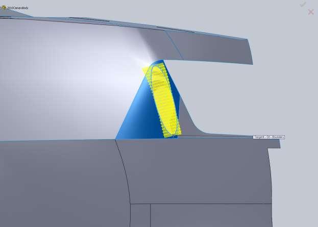
237

238 I knit our new surfaces with the bumper surfaces we have.

239 Next we need to make the surface between our bumper and the tail light panel. I start this with a sketch on the Back Plane trying to match the lines of our bumper opening.

240 From the Top is do the same thing and try to match some of the lines of the car.

241 For the surface I Loft from the edge of our bumper back to the projected curve. I make the surface Tangent to the bumper but I reduce the tangency length. Mine ended up looking good at.6.

242 I purposely drew this surface a little farther in than I think it should be on the car. This was so I could trim it to shape and have some nice edges to work with. From the top I drew a nice spline that had a horizontal relation so when we mirror this surface we won t have a hard edge.

243 On the inside edge I create a Boundary surface using the upper edge of our loft, and the edge of the trunk.

244 This surface will overlap the Right Plane so use the plane to trim the surface.

245 Next is the actual panel around the lights. Looking at images this appears to bulge out a little so I create a sketch on the Right Plane that I think looks right.

246 Then create a Boundary surface.

247 For me this produced some issues in the corner, but that s okay because it needs to be trimmed away for the light.
248
 with no ridge or seam, that you need a horizontal (in our case) relation on your spline.")
249 That pretty much finishes up the rear end so I am going to move on to the roof. I start by drawing the front windshield curve from the front view. It s very important to understand that when you want a surface to cross the mid-plane (after the mirror) with no ridge or seam, that you need a horizontal (in our case) relation on your spline. This is so the mirrored version will end up tangent.

250 Same thing from the Top, make sure you have that Horizontal relation and make sure you project the front view (as a construction line) onto this sketch and apply the relations so that both curves hit the A pillar surface at the same point. If you don t do this you will run into issues because your projected curve will not intersect the surface edge.
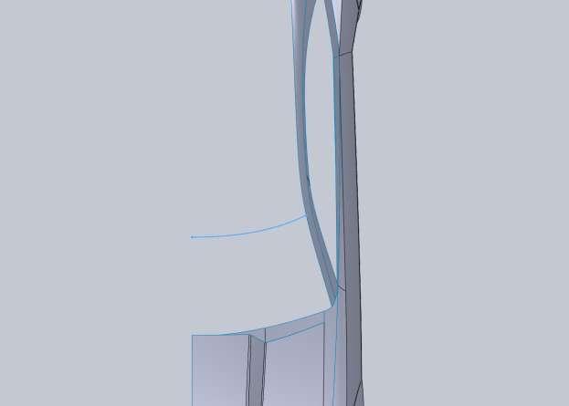
251

252 Same thing for the rear in regards to horizontal relations. Now this car s rear window doesn t hit the Pillar surface but your curve needs to. These curves are going to serve as cross sections for our surface and not the actual boundary of the window.
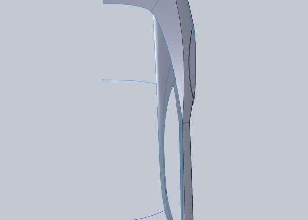
253
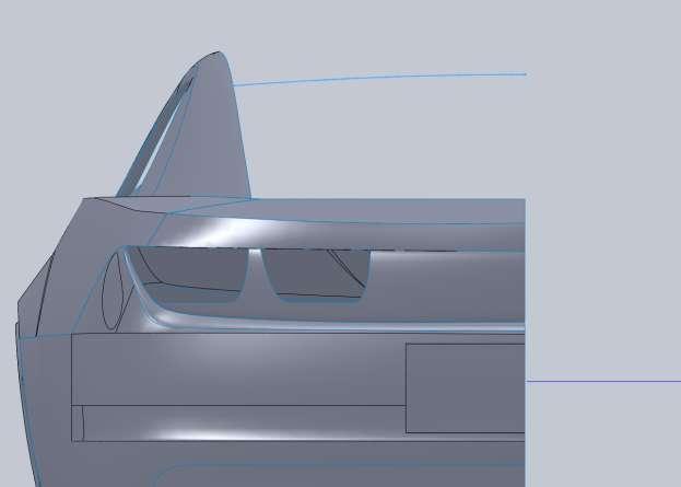
254

255 I do the same thing for the lower edge of the rear window. The reason is because we want to ensure our surface doesn t end up with a seam at the midline for when we make our glass.
256 For the roofline you will need a sketch on the Right Plane. It s important that this curve is coincident to each one of the 3 projected curves in order for our surface to work properly.

257 When creating the boundary surface you will need to alter the amount of curve you use from the rear of the car and the roof line.

258 After you create the surface you can trim the rear window out. I used convert entities on my original top down sketches for the curves to define the roof. Then I used the edge to trim it as shown.

259 The roof of this car also has a sunken feature down the middle of the roof so I setup a front view sketch to trim the roof.

260 From the top I draw a spline that will trim a nice broad arc into this as well.

261 Then on the Right Plane draw a spline that will be a guide for our new roof line. This should be tangent to the front and rear edges of the roof and be below the current roof line.

262 A boundary surface will fill in this area with one important note. You want the surface to have a direction vector influence at the 2d curve. This is for the same reason we add the horizontal relation to our splines. We don t want a hard edge here on the car even though the rest of the car has hard edges. My influence was 40%.
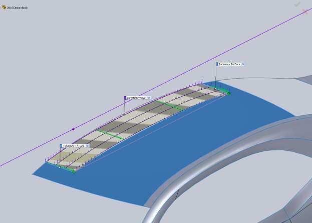
263

264 Then you can simply make a boundary surface to fill that small area between the roof and the new panel.

265 Then knit those together with the rest of the roof. At this point the body is nearly complete so I start adding some fillets. I start with a variable fillet at the back edge of the trunk.

266 At the middle of the car I used a 0.5 radius. Each point from there is also 0.5 until the last point which is The rear fender fillet goes from 0.75 at the back corner to 0.
 and 0.")
267 The door edge all the way to the front is 0, 0.75 (at the seam between the bumper and fender) and 0.75 at the front.

268 Then I add a variable fillet to the tag area. Radius is 0.6 at the center out to 0.

269 The bottom edge is the same as well. The inner edges go from down to 0.

270 Next I make some wheel wells so we can t see right through the car in renders. I do this using a Rule Surface. For type I use Perpendicular to Vector and use the Top Plane as my reference. My surface was 7. Because our rule surface is going to have the same shape as our body I make a vertical line on the Front Plane that is off center and trim the wheel well.

271 Same procedure for the rear and use the same sketch to trim it.

272 To fill these in I make a 3dsketch and draw a straight line to connect the bottom edges. Then I use a boundary surface to fill the back edges in. You can then knit the rule surface to the boundary surface and apply a small fillet to the edges.

273 Next thing I do to add a little more depth to the model is create some Ruled Surfaces around things like the windows. I made my window surfaces Where the meet in the corners I ended up extending them and trimming them to fit each other. I added rule surfaces to the front and rear window as well. These were and I used the Front Plane as my direction reference. Again some of these need to be extended or trimmed or both.

274 Here is an important note for you. I am having issues knitting my pillar surfaces to the rest of the body. Why I am not sure but the issue is a problem since I want to fillet these edges. Since this is my first shot at modeling this car, these are the types of issues that you run into and plan for next time around. I left the Pillars separate from the door/fenders early on because I thought I needed to, I should have knitted them back then. If I were to roll the End of Part line back up and try to knit these together I would produce a bunch of errors/issues that I don t really want to deal with. There are a bunch of little things that pop up along the way that will help you the next time you are modeling and this is one of them. For the same reason I fillet edges early to test how they work, I should have knitted this back then and delete the feature if I didn t need it. Now I m left with an issue pretty far into the model. What I am left with at this point is 5 surfaces. Once I start splitting the body for seams I may find that everything will be fine. My first set of surfaces that are knitted together are these.

275 All the rear bumper pieces.

276 The roof and hood.

277 And then both wheel wells are separate. To make this thing a little more realistic we need to add seams to the panels so it doesn t look like it s all one big piece. I start with the door. I create a sketch to signify the door seam and then use it as a split line for my body surface.
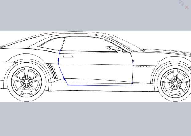
278

279 Now that looks good here but for it to show up in a render we actually need to remove a small amount of material and use rule surfaces to create a drop. So I make another sketch and offset the edges
 I had to split each one, then offset each surface, and delete each one. That s 3 splits, 3 offsets and 3 delete faces.")
280 After I split all my surfaces for the door edge, I make an offset surface of the section within the trim lines and then use delete face to remove the outer face. Now since we have a few different surfaces here (or at least I do) I had to split each one, then offset each surface, and delete each one. That s 3 splits, 3 offsets and 3 delete faces. Also note that you will have to extend, trim and knit these offset surfaces. After you have deleted the faces connecting the door and surrounding surfaces it should become its own surface. This will make it easier to work on the seams. How you make all these seams is really up to you. If you want to try and draw a sill, floor pane and door pillars more power to you. While that would be great, but I don t have any reference photos or the car to figure this out. I am going to use a combination of boundary surfaces, ruled surfaces and trim/extend to get a decent faux door gap. You also have the option to thicken these surfaces to create solids. That may be a much easier way to handle something like this. Each method has benefits and draw backs.
281 After my door surfaces are alone I can go ahead and knit these pieces together. One thing I noticed is that my door surface at the front edge has some unwanted edges. This is because it was split with a Right Plane sketch, but the surface rolled so it s nearly parallel with the top plane. So from a top view I make a sketch to trim the door a little bit more.
282 I also can now go ahead and add a few fillets.

283 One thing to keep in mind is that if you want to thicken this surface into a solid, these fillets just added above will give you errors and you should add them after it is a solid. Here is a shot of the types of issues you will get when thickening a surface into a solid like this.
284 I am going to continue on with surfaces. I will go through adding these surfaces and seams to this door, but the rest of the parts will be up to you entirely. After all the whole point of this is to show you how it s done, not exactly how to do it. Using Ruled Surface type Perpendicular to Vector I select the Top Plane, then make my way around the door edge. There are a few that gave me problems so I just skip them.


285 I leave the top edge and fillet along because of their direction in relation to the Top Plane. For some reason this fillet edge game me issues so I skipped it. Make sure you turn on Trim and Knit in your options for the Ruled Surface.


286 I go back after the surface is created and fill in areas like this using Boundary Surface or Loft. I knit all the surfaces together then concentrate on the top two edges I left out of the Ruled Surface.


287 A Boundary Surface from one edge to the other using the filleted edge as the Dir2 fills it in nicely. Now we have a door that appears to have a little thickness to it. We still need to work around the door frame on the car but a quick render shows that we actually see the door seam.

288 It won t stand out as much once we have a body color piece behind it. We still need some surfaces around the door on the body. Then we have to split the side skirt, the trunk, the hood and the front bumper. First I am going to split the side skirt. This is an interesting case because we don t actually need a gap here. The side skirt will actually lay over the sheet metal hiding the factory edges where the sheet metal is combined and welded together.

289 Once the side skirt is split, use the offset surface button and offset it a small amount. Once offset you can make lofted or boundary surfaces back to the original, then delete the original with delete face. What you are left with is a side skirt that is just slightly outside of the body so in the renders it will really look as though it was an addition and not part of the body.


290 Now through a combination of Ruled Surfaces, some Boundary Surfaces and planning I have made a door seam. At the bottom I made it a little higher and made sure to only knit the surfaces together that I wanted to be the Side Skirt.
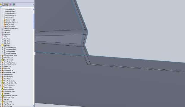
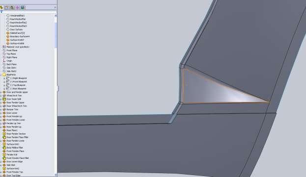
291

292 Also just as I suspected after splitting the body up a few times it let me knit the C pillar to the rest of the body so I will be able to fillet this a little bit down the road. Before I get too carried away with knitting things together I think it s a good time to split the hood and trunk from the rest of the body. Then split the front bumper. This will let us break the body up into is proper sections. For the hood I used the hard seam I left there previously and offset it away from the hood a small amount. After the split, again I used Delete Face to remove the area. I also split the hood at the cowl vent area. The image below shows what the hood surface is now.

293 From this point you should have all the info you need to split the rest of the surfaces and make the call on small details. There are a few more details that need to be handled on this body before its done. Fog light holes need to be cut in the bumper and marker light holes need to be made in the front and rear bumper at our seams. For the marker lights for the time being I just split the front and rear bumper, then changed the appearance of the faces. What we should do is make an offset surface just below, the body then trim a little bit off of this. It will give us a small gap around each light and separate it from the rest of the surface around them.
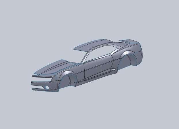
294
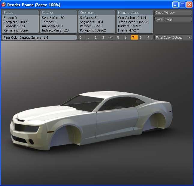
295
Surface Modeling Tutorial
 Surface Modeling Tutorial Complex Surfacing in SolidWorks By Matthew Perez By Matthew Perez Who is this tutorial for? This tutorial assumes that you have prior surfacing knowledge as well as a general
Solidworks 2006 Surface-modeling
 Solidworks 2006 Surface-modeling (Tutorial 2-Mouse) Surface-modeling Solid-modeling A- 1 Assembly Design Design with a Master Model Surface-modeling Tutorial 2A Import 2D outline drawing into Solidworks2006
Copyright by J.W. Zuyderduyn Page 1
 Copyright by J.W. Zuyderduyn www.learnsolidworks.com Page 1 A step by step SolidWorks Tutorial Copyright by J.W. Zuyderduyn www.learnsolidworks.com Page 2 About the Author Hi, my name is Jan-Willem Zuyderduyn
Visualization Insider A Little Background Information
 Visualization Insider A Little Background Information Visualization Insider 2 Creating Backgrounds for 3D Scenes Backgrounds are a critical part of just about every type of 3D scene. Although they are
Porsche 91 1GT D m o d e ling tutorial - by Nim
 orsche 911GT 3D modeling tutorial - by Nimish In this tutorial you will learn to model a car using Spline modeling method. This method is not very much famous as it requires considerable amount of skill
On the Web sun.com/aboutsun/comm_invest STAROFFICE 8 DRAW
 STAROFFICE 8 DRAW Graphics They say a picture is worth a thousand words. Pictures are often used along with our words for good reason. They help communicate our thoughts. They give extra information that
2013 Jan-Willem Zuyderduyn LearnSolidWorks.com 1 P a g e
 2013 Jan-Willem Zuyderduyn LearnSolidWorks.com 1 P a g e A step by step SolidWorks Tutorial 2013 Jan-Willem Zuyderduyn LearnSolidWorks.com 2 P a g e Do you have the SolidWorks files and latest version
TRAINING SESSION Q2 2016
 There are 8 main topics in this training session which focus on the Sketch tools in IRONCAD. Content Sketch... 2 3D Scene Background Settings... 3 Creating a new empty Sketch... 4 Foam with cut out for
Autodesk Inventor Design Exercise 2: F1 Team Challenge Car Developed by Tim Varner Synergis Technologies
 Autodesk Inventor Design Exercise 2: F1 Team Challenge Car Developed by Tim Varner Synergis Technologies Tim Varner - 2004 The Inventor User Interface Command Panel Lists the commands that are currently
UV Mapping to avoid texture flaws and enable proper shading
 UV Mapping to avoid texture flaws and enable proper shading Foreword: Throughout this tutorial I am going to be using Maya s built in UV Mapping utility, which I am going to base my projections on individual
Modeling a Gear Standard Tools, Surface Tools Solid Tool View, Trackball, Show-Hide Snaps Window 1-1
 Modeling a Gear This tutorial describes how to create a toothed gear. It combines using wireframe, solid, and surface modeling together to create a part. The model was created in standard units. To begin,
Quick Crash Scene Tutorial
 Quick Crash Scene Tutorial With Crash Zone or Crime Zone, even new users can create a quick crash scene diagram in less than 10 minutes! In this tutorial we ll show how to use Crash Zone s unique features
Let s Make a Front Panel using FrontCAD
 Let s Make a Front Panel using FrontCAD By Jim Patchell FrontCad is meant to be a simple, easy to use CAD program for creating front panel designs and artwork. It is a free, open source program, with the
The Rectangular Problem
 C h a p t e r 2 The Rectangular Problem In this chapter, you will cover the following to World Class standards: The tools for simple 2D Computer Aided Drafting (CAD) The Command Line and the Tray The Line
SolidWorks 2½D Parts
 SolidWorks 2½D Parts IDeATe Laser Micro Part 1b Dave Touretzky and Susan Finger 1. Create a new part In this lab, you ll create a CAD model of the 2 ½ D key fob below to make on the laser cutter. Select
How to model a car body in T-Splines
 How to model a car body in T-Splines My name is and I ll show you how to model complex cars like the Alfa Romeo 147 gta using the T-Splines Maya plugin and various techniques. This will be useful if you
SketchUp Tool Basics
 SketchUp Tool Basics Open SketchUp Click the Start Button Click All Programs Open SketchUp Scroll Down to the SketchUp 2013 folder Click on the folder to open. Click on SketchUp. Set Up SketchUp (look
SolidWorks Intro Part 1b
 SolidWorks Intro Part 1b Dave Touretzky and Susan Finger 1. Create a new part We ll create a CAD model of the 2 ½ D key fob below to make on the laser cutter. Select File New Templates IPSpart If the SolidWorks
Textures and UV Mapping in Blender
 Textures and UV Mapping in Blender Categories : Uncategorised Date : 21st November 2017 1 / 25 (See below for an introduction to UV maps and unwrapping) Jim s Notes regarding Blender objects, the UV Editor
An Approach to Content Creation for Trainz
 An Approach to Content Creation for Trainz Paul Hobbs Part 6 GMax Basics (Updates and sample files available from http://www.44090digitalmodels.de) Page 1 of 18 Version 3 Index Foreward... 3 The Interface...
The first thing we ll need is some numbers. I m going to use the set of times and drug concentration levels in a patient s bloodstream given below.
 Graphing in Excel featuring Excel 2007 1 A spreadsheet can be a powerful tool for analyzing and graphing data, but it works completely differently from the graphing calculator that you re used to. If you
Geometric Entities for Pilot3D. Copyright 2001 by New Wave Systems, Inc. All Rights Reserved
 Geometric Entities for Pilot3D Copyright 2001 by New Wave Systems, Inc. All Rights Reserved Introduction on Geometric Entities for Pilot3D The best way to develop a good understanding of any Computer-Aided
SOLIDWORKS: Lesson III Patterns & Mirrors. UCF Engineering
 SOLIDWORKS: Lesson III Patterns & Mirrors UCF Engineering Solidworks Review Last lesson we discussed several more features that can be added to models in order to increase their complexity. We are now
SNOWFLAKES PHOTO BORDER - PHOTOSHOP CS6 / CC
 Photo Effects: Snowflakes Photo Border (Photoshop CS6 / CC) SNOWFLAKES PHOTO BORDER - PHOTOSHOP CS6 / CC In this Photoshop tutorial, we ll learn how to create a simple and fun snowflakes photo border,
Skateboard. Hanger. in the Feature Manager and click Sketch. (S) on the Sketch. Line
 on the Sketch. Line") Chapter 3 Skateboard Hanger A. Sketch 1. Step 1. Click File Menu > New, click Part Metric and OK. Step 2. Click Right Plane from the Content toolbar, Fig. 1. in the Feature Manager and click Sketch Step
Chapter 3 Skateboard Hanger A. Sketch 1. Step 1. Click File Menu > New, click Part Metric and OK. Step 2. Click Right Plane from the Content toolbar, Fig. 1. in the Feature Manager and click Sketch Step
Creating an Animated Navigation Bar in InDesign*
 Creating an Animated Navigation Bar in InDesign* *for SWF or FLA export only Here s a digital dilemma: You want to provide navigation controls for readers, but you don t want to take up screen real estate
Inventor 201. Work Planes, Features & Constraints: Advanced part features and constraints
 Work Planes, Features & Constraints: 1. Select the Work Plane feature tool, move the cursor to the rim of the base so that inside and outside edges are highlighted and click once on the bottom rim of the
Rhinoceros Car Modeling Tutorial
 Rhinoceros Car Modeling Tutorial This tutorial will guide you to car nurbs modeling process using Rhinoceros 3.0. To start a car modeling you will need some car images (or sketches) to get an idea of the
two using your LensbAby
 two Using Your Lensbaby 28 Lensbaby Exposure and the Lensbaby When you attach your Lensbaby to your camera for the first time, there are a few settings to review so that you can start taking photos as
Google SketchUp. and SketchUp Pro 7. The book you need to succeed! CD-ROM Included! Kelly L. Murdock. Master SketchUp Pro 7 s tools and features
 CD-ROM Included! Free version of Google SketchUp 7 Trial version of Google SketchUp Pro 7 Chapter example files from the book Kelly L. Murdock Google SketchUp and SketchUp Pro 7 Master SketchUp Pro 7 s
4) Finish the spline here. To complete the spline, double click the last point or select the spline tool again.
 Finish the spline here. To complete the spline, double click the last point or select the spline tool again.") 1) Select the line tool 3) Move the cursor along the X direction (be careful to stay on the X axis alignment so that the line is perpendicular) and click for the second point of the line. Type 0.5 for
1) Select the line tool 3) Move the cursor along the X direction (be careful to stay on the X axis alignment so that the line is perpendicular) and click for the second point of the line. Type 0.5 for
Autodesk Fusion 360: Model. Overview. Modeling techniques in Fusion 360
 Overview Modeling techniques in Fusion 360 Modeling in Fusion 360 is quite a different experience from how you would model in conventional history-based CAD software. Some users have expressed that it
TRAINING SESSION Q3 2016
 There are 6 main topics in this training session which is focusing on 3D Import and 2D Drawing Tips and Tricks in IRONCAD. Content 3D modeling kernels... 2 3D Import... 3 Direct Face Modeling... 5 Unfold
Tangents. In this tutorial we are going to take a look at how tangents can affect an animation.
 Tangents In this tutorial we are going to take a look at how tangents can affect an animation. One of the 12 Principles of Animation is called Slow In and Slow Out. This refers to the spacing of the in
Lesson 1: Creating T- Spline Forms. In Samples section of your Data Panel, browse to: Fusion 101 Training > 03 Sculpt > 03_Sculpting_Introduction.
 3.1: Sculpting Sculpting in Fusion 360 allows for the intuitive freeform creation of organic solid bodies and surfaces by leveraging the T- Splines technology. In the Sculpt Workspace, you can rapidly
Solid Works surfaces tutorial
 Tutorial Surfaces SolidWorks 2015 Example Solid Works surfaces tutorial 2 Make the model of a airplane. The purpose of this tutorial is to practice the commnads with surfaces, obtaining the outer shell
SOLIDWORKS: Lesson 1 - Basics and Modeling. Introduction to Robotics
 SOLIDWORKS: Lesson 1 - Basics and Modeling Fundamentals Introduction to Robotics SolidWorks SolidWorks is a 3D solid modeling package which allows users to develop full solid models in a simulated environment
Create Complex Surfaces
 Create Complex Surfaces In this lesson, you will be introduced to the functionalities available in the Generative Surface Design workbench. Lesson content: Case Study: Surface Design Design Intent Stages
CHAPTER 1 COPYRIGHTED MATERIAL. Finding Your Way in the Inventor Interface
 CHAPTER 1 Finding Your Way in the Inventor Interface COPYRIGHTED MATERIAL Understanding Inventor s interface behavior Opening existing files Creating new files Modifying the look and feel of Inventor Managing
TMG Clerk. User Guide
 User Guide Getting Started Introduction TMG Email Clerk The TMG Email Clerk is a kind of program called a COM Add-In for Outlook. This means that it effectively becomes integrated with Outlook rather than
Installing and Using Trackside Cameras Revised November 2008
 Installing and Using Trackside Cameras Revised November 2008 Trackside cameras are a useful and creative way to add visual interest to your route. Rather than just look out the windshield of the locomotive
Arduino IDE Friday, 26 October 2018
 Arduino IDE Friday, 26 October 2018 12:38 PM Looking Under The Hood Of The Arduino IDE FIND THE ARDUINO IDE DOWNLOAD First, jump on the internet with your favorite browser, and navigate to www.arduino.cc.
CO 2 Shell Car. Body. in the Feature Manager and click Sketch from the context toolbar, Fig. 1. on the Standard Views toolbar.
 CO 2 Shell Car Chapter 2 Body A. Save as "BODY". Step 1. If necessary, open your BLANK file. Step 2. Click File Menu > Save As. Step 3. Key-in BODY for the filename and press ENTER. B. FRONT Wheel Shell.
DOING MORE WITH WORD: MICROSOFT OFFICE 2007
 DOING MORE WITH WORD: MICROSOFT OFFICE 2007 GETTING STARTED PAGE 02 Prerequisites What You Will Learn USING MICROSOFT WORD PAGE 03 Viewing Toolbars Adding and Removing Buttons MORE TASKS IN MICROSOFT WORD
GSAK (Geocaching Swiss Army Knife) GEOCACHING SOFTWARE ADVANCED KLASS GSAK by C3GPS & Major134
 GEOCACHING SOFTWARE ADVANCED KLASS GSAK by C3GPS & Major134") GSAK (Geocaching Swiss Army Knife) GEOCACHING SOFTWARE ADVANCED KLASS GSAK - 102 by C3GPS & Major134 Table of Contents About this Document... iii Class Materials... iv 1.0 Locations...1 1.1 Adding Locations...
GSAK (Geocaching Swiss Army Knife) GEOCACHING SOFTWARE ADVANCED KLASS GSAK - 102 by C3GPS & Major134 Table of Contents About this Document... iii Class Materials... iv 1.0 Locations...1 1.1 Adding Locations...
NCMail: Microsoft Outlook User s Guide
 NCMail: Microsoft Outlook 2007 Email User s Guide Revision 1.1 3/9/2009 This document covers how to use Microsoft Outlook 2007 for accessing your email with the NCMail Exchange email system. The syntax
insight3d quick tutorial
 insight3d quick tutorial What can it do? insight3d lets you create 3D models from photographs. You give it a series of photos of a real scene (e.g., of a building), it automatically matches them and then
Outlook Web Access. In the next step, enter your address and password to gain access to your Outlook Web Access account.
 Outlook Web Access To access your mail, open Internet Explorer and type in the address http://www.scs.sk.ca/exchange as seen below. (Other browsers will work but there is some loss of functionality) In
Bonus Ch. 1. Subdivisional Modeling. Understanding Sub-Ds
 Bonus Ch. 1 Subdivisional Modeling Throughout this book, you ve used the modo toolset to create various objects. Some objects included the use of subdivisional surfaces, and some did not. But I ve yet
Printing Envelopes in Microsoft Word
 Printing Envelopes in Microsoft Word P 730 / 1 Stop Addressing Envelopes by Hand Let Word Print Them for You! One of the most common uses of Microsoft Word is for writing letters. With very little effort
Excel Basics: Working with Spreadsheets
 Excel Basics: Working with Spreadsheets E 890 / 1 Unravel the Mysteries of Cells, Rows, Ranges, Formulas and More Spreadsheets are all about numbers: they help us keep track of figures and make calculations.
Mastering Truspace 7
 How to move your Truespace models in Dark Basic Pro by Vickie Eagle Welcome Dark Basic Users to the Vickie Eagle Truspace Tutorials, In this first tutorial we are going to build some basic landscape models
Vectorworks Essential Tutorial Manual by Jonathan Pickup. Sample
 Vectorworks Essential Tutorial Manual by Jonathan Pickup Table of Contents 0.0 Introduction... iii 0.1 How to Use this Manual... iv 0.2 Real World Sizes... iv 0.3 New Ways of Drawing... v 1.0 Introduction
Download Free Pictures & Wallpaper from the Internet
 Download Free Pictures & Wallpaper from the Internet D 600 / 1 Millions of Free Graphics and Images at Your Fingertips! Discover How To Get Your Hands on Them Almost any type of document you create can
Customizing DAZ Studio
 Customizing DAZ Studio This tutorial covers from the beginning customization options such as setting tabs to the more advanced options such as setting hot keys and altering the menu layout. Introduction:
Math Dr. Miller - Constructing in Sketchpad (tm) - Due via by Friday, Mar. 18, 2016
 - Due via by Friday, Mar. 18, 2016") Math 304 - Dr. Miller - Constructing in Sketchpad (tm) - Due via email by Friday, Mar. 18, 2016 As with our second GSP activity for this course, you will email the assignment at the end of this tutorial
Math 304 - Dr. Miller - Constructing in Sketchpad (tm) - Due via email by Friday, Mar. 18, 2016 As with our second GSP activity for this course, you will email the assignment at the end of this tutorial
Battery Holder. Chapter 9. Boat. A. Front Extrude. Step 1. Click File Menu > New, click Part and OK. SolidWorks 10 BATTERY HOLDER AA BOAT Page 9-1
 Chapter 9 Boat Battery Holder A. Front Extrude. Step 1. Click File Menu > New, click Part and OK. AA Step 2. Click Front (plane) in the Feature Manager and click Sketch from the Content toolbar, Fig. 1.
1.7 Limit of a Function
 1.7 Limit of a Function We will discuss the following in this section: 1. Limit Notation 2. Finding a it numerically 3. Right and Left Hand Limits 4. Infinite Limits Consider the following graph Notation:
Exercise Guide. Published: August MecSoft Corpotation
 VisualCAD Exercise Guide Published: August 2018 MecSoft Corpotation Copyright 1998-2018 VisualCAD 2018 Exercise Guide by Mecsoft Corporation User Notes: Contents 2 Table of Contents About this Guide 4
Alibre Design Tutorial - Simple Revolve Translucent Glass Lamp Globe
 Alibre Design Tutorial - Simple Revolve Translucent Glass Lamp Globe Part Tutorial Exercise 2: Globe-1 In this Exercise, We will set System Parameters first. Then, in sketch mode, we will first Outline
Citrix Connectivity Help. Table of Contents
 Citrix Connectivity Help Table of Contents I. Purpose of this Document II. Print Preview Freezing III. Closing Word/ PD² Correctly IV. Session Reliability V. Reconnecting to Disconnected Applications VI.
FACULTY AND STAFF COMPUTER FOOTHILL-DE ANZA. Office Graphics
 FACULTY AND STAFF COMPUTER TRAINING @ FOOTHILL-DE ANZA Office 2001 Graphics Microsoft Clip Art Introduction Office 2001 wants to be the application that does everything, including Windows! When it comes
Lutheran High North Technology The Finder
 Lutheran High North Technology shanarussell@lutheranhighnorth.org www.lutheranhighnorth.org/technology The Finder Your Mac s filing system is called the finder. In this document, we will explore different
Let s see the use of each option available under create feature line window:
 FEATURE LINE: Feature line is a kind of a line or an object which we can use as a base line or foot print of grading object. In civil 3d if you want use grading tool you have some kind of base or foot
Google SketchUp Design Exercise 1
 Google SketchUp Design Exercise 1 The first thing students like to do in SketchUp is make a basic house and try out different colors and materials. They also love making windows and doors, and trying out
Taskbar: Working with Several Windows at Once
 Taskbar: Working with Several Windows at Once Your Best Friend at the Bottom of the Screen How to Make the Most of Your Taskbar The taskbar is the wide bar that stretches across the bottom of your screen,
Burning CDs in Windows XP
 B 770 / 1 Make CD Burning a Breeze with Windows XP's Built-in Tools If your PC is equipped with a rewritable CD drive you ve almost certainly got some specialised software for copying files to CDs. If
Welcome to Solid Edge University 2015
 #SEU15 Welcome to Solid Edge University 2015 Realize innovation. Surfacing: A Hands-on Experience Solid Edge isn t just a great tool for typical machinery design; it s also very powerful when it comes
Texturing laying out Uv's part I - Levitateme
 Texturing laying out Uv's part I - Levitateme In this tutorial, I am going to try and teach people my method of laying out uvs. I think laying out uvs is a art form, I think everyone has there own style,
Polygon Modeling Basics Chapter 1 - Vertices
 Polygon Modeling Basics Chapter 1 - Vertices In this tutorial we will cover the basic tools necessary for Polygon Modeling using the Vertex sub-object selection. It is less of a how to tutorial and more
Animator Friendly Rigging Part 1
 Animator Friendly Rigging Part 1 Creating animation rigs which solve problems, are fun to use, and don t cause nervous breakdowns. - http://jasonschleifer.com/ - 1- CONTENTS I. INTRODUCTION... 4 What is
The scan tools are used to convert and edit bitmap images so that they can be cut or routed by the Torchmate.
 Scan Tools The scan tools are used to convert and edit bitmap images so that they can be cut or routed by the Torchmate. Upon clicking the Scan tool, the flyout opens exposing the two scanning options.
Lines of Symmetry. Grade 3. Amy Hahn. Education 334: MW 8 9:20 a.m.
 Lines of Symmetry Grade 3 Amy Hahn Education 334: MW 8 9:20 a.m. GRADE 3 V. SPATIAL SENSE, GEOMETRY AND MEASUREMENT A. Spatial Sense Understand the concept of reflection symmetry as applied to geometric
VCarve Pro. Vectric Ltd Unit 2B Dunstall Court Astwood Lane Feckenham B96 6QH UK.
 What's New In VCarve Pro Disclaimer All CNC machines (routing, engraving, and milling) are potentially dangerous and because Vectric Ltd has no control over how the software described in this manual might
CREATING AN ILLUSTRATION WITH THE DRAWING TOOLS
 6 CREATING AN ILLUSTRATION WITH THE DRAWING TOOLS Lesson overview In this lesson, you ll learn how to do the following: Understand paths and anchor points. Draw curved and straight lines with the Pen tool.
Designing Simple Buildings
 Designing Simple Buildings Contents Introduction 2 1. Pitched-roof Buildings 5 2. Flat-roof Buildings 25 3. Adding Doors and Windows 27 9. Windmill Sequence 45 10. Drawing Round Towers 49 11. Drawing Polygonal
1. New document, set to 5in x 5in, no bleed. Color Mode should be default at CMYK. If it s not, changed that when the new document opens.
 art 2413 typography fall 17 software review This exercise will reacquaint students with Adobe Illustrator, Photoshop, and InDesign. These are the three main design programs used by the industry. There
Transforming Selections In Photoshop
 Transforming Selections In Photoshop Written by Steve Patterson. In previous tutorials, we learned how to draw simple shape-based selections with Photoshop s Rectangular and Elliptical Marquee Tools. Using
Parametric Modeling. With. Autodesk Inventor. Randy H. Shih. Oregon Institute of Technology SDC PUBLICATIONS
 Parametric Modeling With Autodesk Inventor R10 Randy H. Shih Oregon Institute of Technology SDC PUBLICATIONS Schroff Development Corporation www.schroff.com www.schroff-europe.com 2-1 Chapter 2 Parametric
Chapter01.fm Page 1 Monday, August 23, :52 PM. Part I of Change. The Mechanics. of Change
 Chapter01.fm Page 1 Monday, August 23, 2004 1:52 PM Part I The Mechanics of Change The Mechanics of Change Chapter01.fm Page 2 Monday, August 23, 2004 1:52 PM Chapter01.fm Page 3 Monday, August 23, 2004
Speed Up Windows by Disabling Startup Programs
 Speed Up Windows by Disabling Startup Programs Increase Your PC s Speed by Preventing Unnecessary Programs from Running Windows All S 630 / 1 When you look at the tray area beside the clock, do you see
Lesson 4: Surface Re-limitation and Connection
 Lesson 4: Surface Re-limitation and Connection In this lesson you will learn how to limit the surfaces and form connection between the surfaces. Lesson contents: Case Study: Surface Re-limitation and Connection
H Stab and V Stab. Chapter 6. Glider. A. Open and Save as "H STAB". Step 1. Open your STABILIZER BLANK file.
 Chapter 6 Glider H Stab and V Stab A. Open and Save as "H STAB". Step 1. Open your STABILIZER BLANK file. Step 2. Click File Menu > Save As. Step 3. Key-in H STAB for the filename and press ENTER. B. Sketch
Structural & Thermal Analysis using the ANSYS Workbench Release 11.0 Environment. Kent L. Lawrence
 ANSYS Workbench Tutorial Structural & Thermal Analysis using the ANSYS Workbench Release 11.0 Environment Kent L. Lawrence Mechanical and Aerospace Engineering University of Texas at Arlington SDC PUBLICATIONS
CHAPTER 1 COPYRIGHTED MATERIAL. Getting to Know AutoCAD. Opening a new drawing. Getting familiar with the AutoCAD and AutoCAD LT Graphics windows
 CHAPTER 1 Getting to Know AutoCAD Opening a new drawing Getting familiar with the AutoCAD and AutoCAD LT Graphics windows Modifying the display Displaying and arranging toolbars COPYRIGHTED MATERIAL 2
Navigating the User Interface
 Navigating the User Interface CHAPTER 1 If you re new to the AutoCAD Civil 3D software environment, then your first experience has probably been a lot like staring at the instrument panel of an airplane.
Skateboard. Hanger. in the Feature Manager and click Sketch on the Context toolbar, Fig. 1. Fig. 2
 Chapter 3 Skateboard Hanger A. Sketch1 Lines. Step 1. Click File Menu > New, click Part Metric and OK. Step 2. Click Right Plane in the Feature Manager and click Sketch on the Context toolbar, Fig. 1.
Graphic Design & Digital Photography. Photoshop Basics: Working With Selection.
 1 Graphic Design & Digital Photography Photoshop Basics: Working With Selection. What You ll Learn: Make specific areas of an image active using selection tools, reposition a selection marquee, move and
Creating T-Spline Forms
 1 / 28 Goals 1. Create a T-Spline Primitive Form 2. Create a T-Spline Revolve Form 3. Create a T-Spline Sweep Form 4. Create a T-Spline Loft Form 2 / 28 Instructions Step 1: Go to the Sculpt workspace
Tips & Tricks for Microsoft Word
 T 330 / 1 Discover Useful Hidden Features to Speed-up Your Work in Word For what should be a straightforward wordprocessing program, Microsoft Word has a staggering number of features. Many of these you
In Wings 3D: Basic Pants
 Modeling for Poser In Wings 3D: Basic Pants Cyberwoman 2010; illustrations by Cyberwoman with the cooperation of Sydney G2. Do not reproduce or redistribute without permission. This tutorial will show
Chapter 10 Working with Graphs and Charts
 Chapter 10: Working with Graphs and Charts 163 Chapter 10 Working with Graphs and Charts Most people understand information better when presented as a graph or chart than when they look at the raw data.
How to Make a Sign. Eagle Plasma LLC. Accessing the included step by step.dxf files
 Eagle Plasma LLC How to Make a Sign Accessing the included step by step.dxf files The following tutorial is designed to teach beginners, screen by screen, to create a simple sign project. In this lesson
XP: Backup Your Important Files for Safety
 XP: Backup Your Important Files for Safety X 380 / 1 Protect Your Personal Files Against Accidental Loss with XP s Backup Wizard Your computer contains a great many important files, but when it comes to
Making parchments and parchment scrolls
 Making parchments and parchment scrolls I am delighted to accept an invitation from Profantasy to present the methods I use to make parchment and parchment scrolls for use as backgrounds in CC3. I hope
Boat. Battery Holder AA
 Chapter 9 Boat Battery Holder AA A. Front Extrude. Step 1. Click File Menu > New, click Part and OK. Step 2. Click Front Plane in the Feature Manager and click Sketch context toolbar, Fig. 1. Step 3. Click
Module 1: Basics of Solids Modeling with SolidWorks
 Module 1: Basics of Solids Modeling with SolidWorks Introduction SolidWorks is the state of the art in computer-aided design (CAD). SolidWorks represents an object in a virtual environment just as it exists
ADOBE PHOTOSHOP Using Masks for Illustration Effects
 ADOBE PHOTOSHOP Using Masks for Illustration Effects PS PREVIEW OVERVIEW In this exercise, you ll see a more illustrative use of Photoshop. You ll combine existing photos with digital art created from
Character Modeling IAT 343 Lab 6. Lanz Singbeil
 Character Modeling IAT 343 Lab 6 Modeling Using Reference Sketches Start by creating a character sketch in a T-Pose (arms outstretched) Separate the sketch into 2 images with the same pixel height. Make
WIRE BASICS ESTIMATED TIME REQUIRED. This tutorial will teach you the basics of sketching wires and using them as contours for solid objects.
 WIRE BASICS This tutorial will teach you the basics of sketching wires and using them as contours for solid objects. ESTIMATED TIME REQUIRED 30 Minutes LEARNING GOALS In this tutorial you will learn how