Chapter 6. Concept Modeling. ANSYS, Inc. Proprietary Inventory # May 11, ANSYS, Inc. All rights reserved.
|
|
|
- Damian Austin
- 6 years ago
- Views:
Transcription
1 Chapter 6 Concept Modeling 6-1
2 Contents Concept Modeling Creating Line Bodies Modifying i Line Bodies Cross Sections Cross Section Alignment Cross Section Offset Surfaces From Lines Surfaces From Sketches Edge Joints Workshop 6-1, Line and Surface Bodies 6-2
3 Concept Modeling The features in the Concept menu are used to create and modify line bodies and/or surface bodies which become FE beam or shell models. To begin Concept Modeling, you can either: Create line or surface bodies using the features in the Draw toolbox to design a 2D sketch and/or generate a 3D model Use the Import external geometry file feature Line bodies can be created using the concept modeling tools: Lines from points Lines from sketches Lines from edges Surface bodies can be created using the concept modeling tools: Surfaces from line bodies Surfaces from sketches Surfaces from 3d edges 6-3
4 Creating Line Bodies Lines From Points: Points can be any 2D sketch points, 3D model vertices or Point Feature (PF) points. A point segment is a straight line connecting two selected points. The feature can produce multiple Line Bodies, depending on the connectivity of the chosen point segments. The Operation field allows Add or Add Frozen choices for line bodies. 6-4
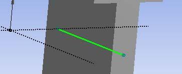
5 Creating Line Bodies Example of Line From Points using 2d points from a rectangular sketch. 2 points are chosen to define a diagonal line body. The green line indicates proposed line segment. Apply the selection then Generate. The Line body is displayed in blue. Line Body Point 1 Point 2 6-5
6 Creating Line Bodies Lines From Sketches: Line bodies created based on sketches and planes from faces Multiple Line Bodies may be created depending on the connectivity of the edges within the base objects Select sketches or planes in the feature tree then Apply in the detail window Multiple sketches, planes, and combinations of sketches and planes can be used as the base object for the creation of line bodies 6-6


7 Creating Line Bodies Example of Lines From Sketches. Sketch created as input for Line Body creation. Lines From Sketches is chosen: Highlight sketch in tree Apply as base object in Detail window 6-7
8 Creating Line Bodies Lines From Edges: Creates line bodies based on existing 2D and 3D model edges Can produce multiple line bodies depending on the connectivity of the selected edges and faces Can select edges and/or faces through two fields in the detail window then Apply 6-8


.")
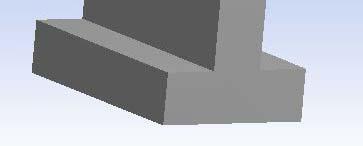
9 Creating Line Bodies Example of Lines From Edges. 3D solid created as input for Line Body creation. Lines From Edges is chosen: Select faces on model. Face boundaries will become line bodies (alternately select 3d edges directly). Apply as base object in Detail window Note: in this case 2 line bodies are created due to the edge connectivity. 6-9
. Example: Selected line Fraction = 0.5 Fraction = 0.")
10 Modifying Line Bodies Split Line Body: Splits line body edges into two pieces Split location is controlled by the Fraction property (e.g. 0.5 = split in half). Example: Selected line Fraction = 0.5 Fraction =
11 Cross Sections Cross Sections: Cross sections are attributes assigned to line bodies to define beam properties in the FE simulation In DM, cross sections are represented by sketches and are controlled by a set of dimensions Note: DesignModeler uses a different coordinate system for cross sections than the one used in the ANSYS environment (described later) 6-11


12 Cross Sections Cross sections are selected from the Concept menu A cross section branch is inserted in the tree where each chosen cross section is listed Concept menu Display Tree Cross Section menu 6-12


13 Cross Sections Highlight the cross section in the Tree to modify dimensions in the Details window Desig gnmodeler 6-13


14 Cross Sections Dimension Editing Cross section dimensions can be repositioned via a RMB and choosing Move Dimensions 6-14
15 Cross Sections Assigning a cross section to a line body: Highlight the line body in the Tree A cross section property appears in the detail window Click in this field and choose the desired cross section from the drop down list 6-15
16 Cross Sections A user integrated section can be defined in DM The cross section is not sketched, rather the cross section s properties are placed in the details window A = Area of section. Ixx = Moment of inertia about the x axis. Ixy = Product of inertia. Iyy = Moment of inertia about the y axis. Iw =Warping constant. J = Torsional constant. CGx = X coordinate of centroid. CGy = Y coordinate of centroid. SHx = X coordinate of shear center. SHy = Y coordinate of shear center. 6-16
17 Cross Section Alignment As shown below in DesignModeler the cross section lies in the XY plane: Cross section alignment is defined by: A local or cross section +Y direction Default alignment is with the global +Y direction unless that would result in an invalid alignment in which case +Z is used Note: In the ANSYS S Classic Environment, the cross section lies in the YZ plane and uses the X direction as the edge tangent. This difference in orientation has no bearing on the analysis. Y Cross Section Edge Tangent 6-17
18 Cross Section Alignment A color code is used to indicate cross section status for line bodies: Violet: no cross section assigned Black: cross section assigned with valid alignment Red: cross section assigned with invalid alignment The line body icons in the tree have similar visual aids: Green: cross section assigned with valid cross section alignment Yellow: no cross section assigned or default alignment Red: invalid cross section alignment 6-18


19 Cross Section Alignment Checking alignment can be done graphically using the View menu: Choose Show Cross Section Alignments Green arrow = +Y, blue arrow = edge tangent of cross section Or choose Cross Section Solids +Y Edge Tangent 6-19
20 Cross Section Alignment Because a default alignment is chosen cross section orientation will almost always need to be modified. There are 2 methods for cross section alignment, selection and vector: The selection method uses existing geometry (edges, points, etc.) as alignment reference The vector method uses input according to X, Y, Z coordinate directions For either method a rotation angle can be input and/or the orientation reversed Selection Method Vector Method 6-20
21 Cross Section Alignment Modifying the cross section orientation by vector: Switch to Vector alignment mode Enter the desired coordinate values Enter rotation ti angle if desired Reverse orientation if desired 6-21
: 1.")

22 Cross Section Alignment Modifying the cross section orientation by selection (several examples follow): 1. Select the line body to be aligned in graphics window 3. Select the geometry to be used for alignment 2. With Selection method active click in the alignment field 6-22


23 Cross Section Alignment Alignment using lines or axes. Line chosen for alignment Y Axis chosen for alignment Y Edge Tangent 6-23


24 Cross Section Alignment Alignment using face normal. Y Desig gnmodeler Alignment Faces Y 6-24

25 Cross Section Alignment Alignment using sketch points. Note: the order of point selection determines cross section alignment. 1 2D points 2 Selected Line Body Y Edge Tangent 6-25
26 Cross Section Offset Cross Section Offset: After assigning a cross section to a line body, the Detail property allows users to specify the type of offset to use with the cross section: Centroid: The cross section is centered on the line body according to its centroid (default) Shear Center: The cross section is centered on the line body according to its shear center Note the graphical display for centroid and shear center appear the same however, when analyzed, the shear center is used Origin: The cross section is not offset and is taken exactly as it appears in its sketch Examples next page 6-26


")


27 Cross Section Offset Origin offset (no offset) DesignModele er Line Body Line Body with cross section displayed Centroid/Shear Center offset 6-27


28 Surfaces From Lines Surfaces From Lines: Creates surface body using line body edges as the boundary Line body edges must form non-intersecting closed loops Each closed loop creates a frozen Surface Body The loops should form a shape such that a simple surface can be inserted into the model: Planes, cylinders, tori, cones, spheres and simple twisted surfaces Planar surface Twisted surface Details window: Flip surface normals Input thickness which will be transferred to the FE model 6-28


 Result is")
29 Surfaces From Lines Notes on surface from lines: A line body with no cross section can be used to tie together surface models. In this case the line body acts merely as a mechanism to insure a continuous mesh at the surface boundaries. 2S Surface Bodies Line Body (no cross section) Result is continuous FE mesh at surface interface 6-29
30 Surfaces From Sketches Surfaces From Sketches: Creates surface bodies using sketches as boundaries (single or multiple sketches are OK) Base sketches must be closed profiles which are not self intersecting May choose to Add or Add Frozen operations Can reverse normal direction No in Orient With Plane Normal field Can enter thickness which will be used in creating the FE model 6-30


31 Surfaces From Sketches 2 ways to identify sketch for operation Click in the Base Objects field Select the desired sketch from the tree then Apply Select a portion of the desired sketch in the graphics window then Apply 6-31

32 Surfaces From Edges Surfaces from Edges: Creates surfaces from existing body edges Can be solid or line body edges. Edges must produce non-intersecting closed loops. Example: Existing solid body edges are New, frozen, surface body generated selected for new surface boundary. (note, solid body is hidden). 6-32
.")

33 Surfaces Patch Surface patching attempts to fill gaps in the model. Uses similar healing methods as face delete (natural and patch). Complex gaps may result in multiple surfaces being created to fill them. Example: 2 holes selected for patching Two patches created using multiple surfaces 6-33


34 Edge Joints Edge Joints are the glue that holds together bodies where a continuous mesh is desired. Creating surface and/or line multibody parts with coincident edges results in automatic creation of edge joints. Joints can be created manually where no coincident topology exists. 6-34

35 Edge Joints Edge Joints can be viewed by turning on the Edge Joints option in the View menu: Edge joints are displayed in either blue or red. Blue: edge joint is contained in properly defined multi-body part Red: edge joint not grouped into the same part No Edge Joint With Edge Joint 6-35
36 Line and Surface Bodies Workshop


37 Workshop 6-1, Line and Surface Bodies Goals: Create a sketch representing beams used to stiffen a panel. Create a line body from the sketch. Choose a beam cross section to be used and assign it to the line body. Create a surface model representing the panel. >File>New, or Start Page: Choose to create new geometry At the prompt, set the length unit to millimeter 6-37


38 Workshop 6-1, Line and Surface Bodies Create a rectangle [Sketch] > Rectangle 1. Place the cursor near the origin until P appears, click then drag to define the rectangle Click >Look At & >Zoom to Fit tool buttons, and Triad ISO Ball as desired
![Workshop 6-1, Line and Surface Bodies Dimension the rectangle 600X300 mm as shown [Sketch] > Dimension > General](/docs-images/75/72756551/images/39-2.jpg "Horizontal = 600 mm Vertical = 300 mm Fit the sketch and move dimensions as necessary [Sketch] > Dimension > Move")
39 Workshop 6-1, Line and Surface Bodies Dimension the rectangle 600X300 mm as shown [Sketch] > Dimension > General Horizontal = 600 mm Vertical = 300 mm Fit the sketch and move dimensions as necessary [Sketch] > Dimension > Move 6-39


40 Workshop 6-1, Line and Surface Bodies Add 2 vertical lines and dimension as shown [Sketch] > Draw > Line 2. Place the cursor near the top line until the C coincidence constraint appears. Move the cursor to the bottom line until the C appears and a V i indicating a vertical constraint. 3. Repeat for second line 2 3 Apply horizontal dimensions i as shown. [Sketch] > Dimension > Horizontal Adjust Details so all dimensions are as indicated 6-40


41 Workshop 6-1, Line and Surface Bodies Create a Line Body from Sketch1 [Main Menu] > Concept > Lines From Sketches 4. Select Sketch1 from the Tree (click the + near the XYPlane to expand that branch if necessary) and >Details>Apply it as the base object 5. Click >Generate


42 Workshop 6-1, Line and Surface Bodies Select a rectangular tube type cross section: [Main Menu] > Concept > Cross Section > Rectangular Tube After selection, the cross section is displayed with its dimensions. In this case we will use the default dimensions. If desired the cross section Details can be changed to modify the cross section. 6-42


![[tree] > 1 Part, 1 Body > Line Body (at bottom](/docs-images/75/72756551/images/43-6.jpg "of tree) 7.")
43 Workshop 6-1, Line and Surface Bodies With a cross section selected we now need to associate it with our line body. 6. Highlight the line body in the tree and the details shows that no cross section is yet associated with it. [tree] > 1 Part, 1 Body > Line Body (at bottom of tree) 7. Click in the Cross Section field 6 8. Choose RecTube1 from the drop down list


![[Main Menu] > View](/docs-images/75/72756551/images/44-8.jpg ">Sh Show Cross")
44 Workshop 6-1, Line and Surface Bodies 9. After assigning the cross section to the line body the default display shows the line body with its cross section alignment (see right). We can also display the beam with the cross section displayed as a solid. [Main Menu] > View >Sh Show Cross Sections Solids 6-44

![[Main Menu] > Concept > Surfaces From Lines Hold the control key and select the 4 lines](/docs-images/75/72756551/images/45-3.jpg "shown at right.")
45 Workshop 6-1, Line and Surface Bodies The next step is to create the surfaces between the beams. These surfaces will be shell meshed in the FE simulation. 10. [Main Menu] > Concept > Surfaces From Lines Hold the control key and select the 4 lines shown at right. (or can hold down LMB and sweep mouse over lines to be group selected) 11. >Apply


46 Workshop 6-1, Line and Surface Bodies 12. >Generate the Surface Body. Note: a frozen surface body is created, bounded by the selected lines Repeat the previous steps to create two more surface bodies 12 >Generate as necessary 6-46

.")


47 Workshop 6-1, Line and Surface Bodies The final modeling operation is to place all the bodies into a single part (multi-body yp part). We must do this to insure that, when meshed, each boundary recognizes its neighbor resulting in a continuous mesh. Set the Selection Filter to Bodies. In the graphics window right mouse click and choose >Select All 6-47


48 Workshop 6-1, Line and Surface Bodies With all bodies selected, again right click in the graphics window and choose Form New Part. By examining the Tree notice a single part has been formed which contains 4 bodies. 6-48


 part, nodal connectivity it")
49 Workshop 6-1, Line and Surface Bodies Shown here we have moved to a Simulation environment in Workbench and meshed the geometry. By grouping all bodies into a common (single) part, nodal connectivity it is insured. 6-49
50
Introduction to ANSYS DesignModeler
 Lecture 9 Beams and Shells 14. 5 Release Introduction to ANSYS DesignModeler 2012 ANSYS, Inc. November 20, 2012 1 Release 14.5 Beams & Shells The features in the Concept menu are used to create and modify
Introduction to ANSYS DesignModeler
 Lecture 5 Modeling 14. 5 Release Introduction to ANSYS DesignModeler 2012 ANSYS, Inc. November 20, 2012 1 Release 14.5 Preprocessing Workflow Geometry Creation OR Geometry Import Geometry Operations Meshing
Structural & Thermal Analysis Using the ANSYS Workbench Release 12.1 Environment
 ANSYS Workbench Tutorial Structural & Thermal Analysis Using the ANSYS Workbench Release 12.1 Environment Kent L. Lawrence Mechanical and Aerospace Engineering University of Texas at Arlington SDC PUBLICATIONS
Introduction And Overview ANSYS, Inc. All rights reserved. 1 ANSYS, Inc. Proprietary
 Introduction And Overview 2006 ANSYS, Inc. All rights reserved. 1 ANSYS, Inc. Proprietary The ANSYS Workbench represents more than a general purpose engineering tool. It provides a highly integrated engineering
Structural & Thermal Analysis using the ANSYS Workbench Release 11.0 Environment. Kent L. Lawrence
 ANSYS Workbench Tutorial Structural & Thermal Analysis using the ANSYS Workbench Release 11.0 Environment Kent L. Lawrence Mechanical and Aerospace Engineering University of Texas at Arlington SDC PUBLICATIONS
Finite Element Course ANSYS Mechanical Tutorial Tutorial 3 Cantilever Beam
 Problem Specification Finite Element Course ANSYS Mechanical Tutorial Tutorial 3 Cantilever Beam Consider the beam in the figure below. It is clamped on the left side and has a point force of 8kN acting
NX Tutorial - Centroids and Area Moments of Inertia ENAE 324 Aerospace Structures Spring 2015
 NX will automatically calculate area and mass information about any beam cross section you can think of. This tutorial will show you how to display a section s centroid, principal axes, 2 nd moments of
Autodesk Inventor 2019 and Engineering Graphics
 Autodesk Inventor 2019 and Engineering Graphics An Integrated Approach Randy H. Shih SDC PUBLICATIONS Better Textbooks. Lower Prices. www.sdcpublications.com Powered by TCPDF (www.tcpdf.org) Visit the
Additional Surface Tools
 Additional Surface Tools Several additional surface tools, techniques, and related functions are available. This supplement provides a brief introduction to those functions. Panel Part Features Replace
Solidworks 2006 Surface-modeling
 Solidworks 2006 Surface-modeling (Tutorial 2-Mouse) Surface-modeling Solid-modeling A- 1 Assembly Design Design with a Master Model Surface-modeling Tutorial 2A Import 2D outline drawing into Solidworks2006
SOLIDWORKS 2016 and Engineering Graphics
 SOLIDWORKS 2016 and Engineering Graphics An Integrated Approach Randy H. Shih SDC PUBLICATIONS Better Textbooks. Lower Prices. www.sdcpublications.com Powered by TCPDF (www.tcpdf.org) Visit the following
CATIA V5 Parametric Surface Modeling
 CATIA V5 Parametric Surface Modeling Version 5 Release 16 A- 1 Toolbars in A B A. Wireframe: Create 3D curves / lines/ points/ plane B. Surfaces: Create surfaces C. Operations: Join surfaces, Split & Trim
A Comprehensive Introduction to SolidWorks 2011
 A Comprehensive Introduction to SolidWorks 2011 Godfrey Onwubolu, Ph.D. SDC PUBLICATIONS www.sdcpublications.com Schroff Development Corporation Chapter 2 Geometric Construction Tools Objectives: When
3. Preprocessing of ABAQUS/CAE
 3.1 Create new model database 3. Preprocessing of ABAQUS/CAE A finite element analysis in ABAQUS/CAE starts from create new model database in the toolbar. Then save it with a name user defined. To build
SolidWorks 2013 and Engineering Graphics
 SolidWorks 2013 and Engineering Graphics An Integrated Approach Randy H. Shih SDC PUBLICATIONS Schroff Development Corporation Better Textbooks. Lower Prices. www.sdcpublications.com Visit the following
ES 230 Strengths Intro to Finite Element Modeling & Analysis Homework Assignment 2
 ES 230 Strengths Intro to Finite Element Modeling & Analysis Homework Assignment 2 In this homework assignment you will use your rapidly developing ANSYS skill set to model and analyze three different
CATIA Surface Design
 CATIA V5 Training Exercises CATIA Surface Design Version 5 Release 19 September 2008 EDU_CAT_EN_GS1_FX_V5R19 Table of Contents (1/2) Creating Wireframe Geometry: Recap Exercises 4 Creating Wireframe Geometry:
2. Give an example of a non-constant function f(x, y) such that the average value of f over is 0.
 such that the average value of f over is 0.") Midterm 3 Review Short Answer 2. Give an example of a non-constant function f(x, y) such that the average value of f over is 0. 3. Compute the Riemann sum for the double integral where for the given grid
Midterm 3 Review Short Answer 2. Give an example of a non-constant function f(x, y) such that the average value of f over is 0. 3. Compute the Riemann sum for the double integral where for the given grid
Mid-Surface Creation. Mid-Surface Tool:
 Mid-Surface Creation Mid-Surface Tool: Reduces 3D geometry of constant thickness to a simplified shell representation ti Automatically places surface body at mid point between 3D face pairs Allows shell
Torsional-lateral buckling large displacement analysis with a simple beam using Abaqus 6.10
 Torsional-lateral buckling large displacement analysis with a simple beam using Abaqus 6.10 This document contains an Abaqus tutorial for performing a buckling analysis using the finite element program
Exercise Guide. Published: August MecSoft Corpotation
 VisualCAD Exercise Guide Published: August 2018 MecSoft Corpotation Copyright 1998-2018 VisualCAD 2018 Exercise Guide by Mecsoft Corporation User Notes: Contents 2 Table of Contents About this Guide 4
Piping Design. Site Map Preface Getting Started Basic Tasks Advanced Tasks Customizing Workbench Description Index
 Piping Design Site Map Preface Getting Started Basic Tasks Advanced Tasks Customizing Workbench Description Index Dassault Systèmes 1994-2001. All rights reserved. Site Map Piping Design member member
3D Design with 123D Design
 3D Design with 123D Design Introduction: 3D Design involves thinking and creating in 3 dimensions. x, y and z axis Working with 123D Design 123D Design is a 3D design software package from Autodesk. A
Module 1: Basics of Solids Modeling with SolidWorks
 Module 1: Basics of Solids Modeling with SolidWorks Introduction SolidWorks is the state of the art in computer-aided design (CAD). SolidWorks represents an object in a virtual environment just as it exists
Selective Space Structures Manual
 Selective Space Structures Manual February 2017 CONTENTS 1 Contents 1 Overview and Concept 4 1.1 General Concept........................... 4 1.2 Modules................................ 6 2 The 3S Generator
Equipment Support Structures
 Equipment Support Structures Overview Conventions What's New? Getting Started Setting Up Your Session Creating a Simple Structural Frame Creating Non-uniform Columns Creating Plates with Openings Bracing
Equipment Support Structures
 Page 1 Equipment Support Structures Preface Using This Guide Where to Find More Information Conventions What's New? Getting Started Setting Up Your Session Creating a Simple Structural Frame Creating Non-uniform
Create a Rubber Duck. This tutorial shows you how to. Create simple surfaces. Rebuild a surface. Edit surface control points. Draw and project curves
 Page 1 of 24 Create a Rubber Duck This exercise focuses on the free form, squishy aspect. Unlike the flashlight model, the exact size and placement of the objects is not critical. The overall form is the
Lesson 1 Parametric Modeling Fundamentals
 1-1 Lesson 1 Parametric Modeling Fundamentals Create Simple Parametric Models. Understand the Basic Parametric Modeling Process. Create and Profile Rough Sketches. Understand the "Shape before size" approach.
Autodesk Inventor - Basics Tutorial Exercise 1
 Autodesk Inventor - Basics Tutorial Exercise 1 Launch Inventor Professional 2015 1. Start a New part. Depending on how Inventor was installed, using this icon may get you an Inch or Metric file. To be
Appendix B: Creating and Analyzing a Simple Model in Abaqus/CAE
 Getting Started with Abaqus: Interactive Edition Appendix B: Creating and Analyzing a Simple Model in Abaqus/CAE The following section is a basic tutorial for the experienced Abaqus user. It leads you
KEYCREATOR 3D Direct Modeling Software
 KeyCreator Lesson KC5107 Graft The Graft Function is a powerful partner to the Prune Function that we used earlier. You will typically use the Graft Function immediately after performing a pruning operation
Lesson 1: Creating T- Spline Forms. In Samples section of your Data Panel, browse to: Fusion 101 Training > 03 Sculpt > 03_Sculpting_Introduction.
 3.1: Sculpting Sculpting in Fusion 360 allows for the intuitive freeform creation of organic solid bodies and surfaces by leveraging the T- Splines technology. In the Sculpt Workspace, you can rapidly
Creating T-Spline Forms
 1 / 28 Goals 1. Create a T-Spline Primitive Form 2. Create a T-Spline Revolve Form 3. Create a T-Spline Sweep Form 4. Create a T-Spline Loft Form 2 / 28 Instructions Step 1: Go to the Sculpt workspace
Parametric Modeling. With. Autodesk Inventor. Randy H. Shih. Oregon Institute of Technology SDC PUBLICATIONS
 Parametric Modeling With Autodesk Inventor R10 Randy H. Shih Oregon Institute of Technology SDC PUBLICATIONS Schroff Development Corporation www.schroff.com www.schroff-europe.com 2-1 Chapter 2 Parametric
Solid surface modeling in AutoCAD
 Solid surface modeling in AutoCAD Introduction into 3D modeling Managing views of 3D model Coordinate Systems 1 3D model advantages ability to view the whole model looking inside the model collision checking
Education Curriculum Surface Design Specialist
 Education Curriculum Surface Design Specialist Invest your time in imagining next generation designs. Here s what we will teach you to give shape to your imagination. CATIA Surface Design Specialist CATIA
Advanced Meshing Tools
 Page 1 Advanced Meshing Tools Preface Using This Guide More Information Conventions What's New? Getting Started Entering the Advanced Meshing Tools Workbench Defining the Surface Mesh Parameters Setting
LAB # 2 3D Modeling, Properties Commands & Attributes
 COMSATS Institute of Information Technology Electrical Engineering Department (Islamabad Campus) LAB # 2 3D Modeling, Properties Commands & Attributes Designed by Syed Muzahir Abbas 1 1. Overview of the
Introduction to SolidWorks Basics Materials Tech. Wood
 Introduction to SolidWorks Basics Materials Tech. Wood Table of Contents Table of Contents... 1 Book End... 2 Introduction... 2 Learning Intentions... 2 Modelling the Base... 3 Modelling the Front... 10
Chair. Top Rail. on the Standard Views toolbar. (Ctrl-7) on the Weldments toolbar. at bottom left corner of display to deter- mine sketch plane.
 on the Weldments toolbar. at bottom left corner of display to deter- mine sketch plane.") Chapter 7 A. 3D Sketch. Step 1. If necessary, open your CHAIR file. Chair Top Rail Step 2. Click Isometric on the Standard Views toolbar. (Ctrl-7) Step 3. Zoom in around top of back leg, Fig. 1. To zoom,
Chapter 7 A. 3D Sketch. Step 1. If necessary, open your CHAIR file. Chair Top Rail Step 2. Click Isometric on the Standard Views toolbar. (Ctrl-7) Step 3. Zoom in around top of back leg, Fig. 1. To zoom,
Publication Number spse01695
 XpresRoute (tubing) Publication Number spse01695 XpresRoute (tubing) Publication Number spse01695 Proprietary and restricted rights notice This software and related documentation are proprietary to Siemens
3D Modeling and Design Glossary - Beginner
 3D Modeling and Design Glossary - Beginner Align: to place or arrange (things) in a straight line. To use the Align tool, select at least two objects by Shift left-clicking on them or by dragging a box
Module 1.7W: Point Loading of a 3D Cantilever Beam
 Module 1.7W: Point Loading of a 3D Cantilever Beam Table of Contents Page Number Problem Description 2 Theory 2 Workbench Analysis System 4 Engineering Data 5 Geometry 6 Model 11 Setup 13 Solution 14 Results
Finite Element Analysis using ANSYS Mechanical APDL & ANSYS Workbench
 Finite Element Analysis using ANSYS Mechanical APDL & ANSYS Workbench Course Curriculum (Duration: 120 Hrs.) Section I: ANSYS Mechanical APDL Chapter 1: Before you start using ANSYS a. Introduction to
Freeform / Freeform PLUS
 Freeform / Freeform PLUS WORKING WITH FREEFORM Work from Coarse Clay to Fine When creating new models from scratch, it is best to first create a rough shape using a coarse clay setting such as Rough Shape
Module 4A: Creating the 3D Model of Right and Oblique Pyramids
 Inventor (5) Module 4A: 4A- 1 Module 4A: Creating the 3D Model of Right and Oblique Pyramids In Module 4A, we will learn how to create 3D solid models of right-axis and oblique-axis pyramid (regular or
Module 2 Review. Assemblies and Rendering. Why Use Assemblies. Assemblies - Key Concepts. Sketch Planes Sketched Features.
 Module 2 Review Assemblies and Rendering EF 101 Modules 3.1, 3.2 Sketch Planes Sketched Features Extrude, Revolve Placed Features Hole, Fillet, Chamfer, Shell, Rect. Pattern Drawing Views Base, Ortho,
AutoCAD 2009 Tutorial
 AutoCAD 2009 Tutorial Second Level: 3D Modeling Randy H. Shih Oregon Institute of Technology SDC PUBLICATIONS Schroff Development Corporation www.schroff.com Better Textbooks. Lower Prices. AutoCAD 2009
FARO Scanning Plugin
 FARO Scanning Plugin for Geomagic Studio 6 service release 4, Geomagic Qualify 6 service release 2, and Geomagic Qualify 7 Document version B Copyright 2004, Raindrop Geomagic, Inc. The FARO scanner is
Module 5: Creating Sheet Metal Transition Piece Between a Square Tube and a Rectangular Tube with Triangulation
 1 Module 5: Creating Sheet Metal Transition Piece Between a Square Tube and a Rectangular Tube with Triangulation In Module 5, we will learn how to create a 3D folded model of a sheet metal transition
Lesson 4: Surface Re-limitation and Connection
 Lesson 4: Surface Re-limitation and Connection In this lesson you will learn how to limit the surfaces and form connection between the surfaces. Lesson contents: Case Study: Surface Re-limitation and Connection
Creating and Analyzing a Simple Model in Abaqus/CAE
 Appendix B: Creating and Analyzing a Simple Model in Abaqus/CAE The following section is a basic tutorial for the experienced Abaqus user. It leads you through the Abaqus/CAE modeling process by visiting
Lesson 14 Blends. For Resources go to > click on the Creo Parametric 2.0 Book cover
 Lesson 14 Blends Figure 14.1 Cap OBJECTIVES Create a Parallel Blend feature Use the Shell Tool Create a Hole Pattern REFERENCES AND RESOURCES For Resources go to www.cad-resources.com > click on the Creo
Inventor. Additional Surface Tools. Replacing Faces
 Additional Surface Tools Inventor includes several additional surface tools, techniques, and related functions. Surface tools are appropriate for some basic applications, and are commonly used when other
Module 4B: Creating Sheet Metal Parts Enclosing The 3D Space of Right and Oblique Pyramids With The Work Surface of Derived Parts
 Inventor (5) Module 4B: 4B- 1 Module 4B: Creating Sheet Metal Parts Enclosing The 3D Space of Right and Oblique Pyramids With The Work Surface of Derived Parts In Module 4B, we will learn how to create
Google SketchUp. and SketchUp Pro 7. The book you need to succeed! CD-ROM Included! Kelly L. Murdock. Master SketchUp Pro 7 s tools and features
 CD-ROM Included! Free version of Google SketchUp 7 Trial version of Google SketchUp Pro 7 Chapter example files from the book Kelly L. Murdock Google SketchUp and SketchUp Pro 7 Master SketchUp Pro 7 s
Revised Iain A MacLeod
 LUSAS User Guidelines Revised 20.06.14 Iain A MacLeod Contents 1 Geometrical features and meshes... 1 2 Toolbars... 1 3 Inserting points... 1 4 Inserting a line between two points... 1 5 Creating a dataset...
ME 442. Marc/Mentat-2011 Tutorial-1
 ME 442 Overview Marc/Mentat-2011 Tutorial-1 The purpose of this tutorial is to introduce the new user to the MSC/MARC/MENTAT finite element program. It should take about one hour to complete. The MARC/MENTAT
Publication Number spse01695
 XpresRoute (tubing) Publication Number spse01695 XpresRoute (tubing) Publication Number spse01695 Proprietary and restricted rights notice This software and related documentation are proprietary to Siemens
3D ModelingChapter1: Chapter. Objectives
 Chapter 1 3D ModelingChapter1: The lessons covered in this chapter familiarize you with 3D modeling and how you view your designs as you create them. You also learn the coordinate system and how you can
COMPUTER AIDED DESIGN CURRICULLOM RHINO BASED 3D DESIGN
 COMPUTER AIDED DESIGN CURRICULLOM RHINO BASED 3D DESIGN S.no. CONTENTS Page no S. no. CONTENTS PAGE no. 1. Introduction 1 2. Necessary of Rhino in Designing 2 3. Working with 3D Models 3 4. Object Types
CECOS University Department of Electrical Engineering. Wave Propagation and Antennas LAB # 1
 CECOS University Department of Electrical Engineering Wave Propagation and Antennas LAB # 1 Introduction to HFSS 3D Modeling, Properties, Commands & Attributes Lab Instructor: Amjad Iqbal 1. What is HFSS?
Workbench Tutorial Flow Over an Airfoil, Page 1 ANSYS Workbench Tutorial Flow Over an Airfoil
 Workbench Tutorial Flow Over an Airfoil, Page 1 ANSYS Workbench Tutorial Flow Over an Airfoil Authors: Scott Richards, Keith Martin, and John M. Cimbala, Penn State University Latest revision: 17 January
QuickTutor. An Introductory SilverScreen Modeling Tutorial. Solid Modeler
 QuickTutor An Introductory SilverScreen Modeling Tutorial Solid Modeler TM Copyright Copyright 2005 by Schroff Development Corporation, Shawnee-Mission, Kansas, United States of America. All rights reserved.
Additional Exercises. You will perform the following exercises to practice the concepts learnt in this course:
 Additional Exercises You will perform the following exercises to practice the concepts learnt in this course: Master Exercise : Mobile Phone Plastic Bottle Exercise 1 Master Exercise : Mobile Phone In
Lesson 14 Blends. For Resources go to > click on the Creo Parametric Book cover
 Lesson 14 Blends Figure 14.1 Cap OBJECTIVES Create a Parallel Blend feature Use the Shell Tool Create a Swept Blend REFERENCES AND RESOURCES For Resources go to www.cad-resources.com > click on the Creo
User Guide. for. JewelCAD Professional Version 2.0
 User Guide Page 1 of 121 User Guide for JewelCAD Professional Version 2.0-1 - User Guide Page 2 of 121 Table of Content 1. Introduction... 7 1.1. Purpose of this document... 7 2. Launch JewelCAD Professional
S206E Lecture 3, 5/15/2017, Rhino 2D drawing an overview
 Copyright 2017, Chiu-Shui Chan. All Rights Reserved. S206E057 Spring 2017 Rhino 2D drawing is very much the same as it is developed in AutoCAD. There are a lot of similarities in interface and in executing
GDL Toolbox 2 Reference Manual
 Reference Manual Archi-data Ltd. Copyright 2002. New Features Reference Manual New Save GDL command Selected GDL Toolbox elements can be exported into simple GDL scripts. During the export process, the
Assembly Design: A Hands-On Experience
 Mark Thompson Sr. Application Engineer Assembly Design: A Hands-On Experience Solid Edge University 2014 May 12-14, Atlanta, GA, USA SOLID EDGE UNIVERSITY 2014 Re-imagine What s Possible #SEU14 Agenda
Multiframe Oct 2008
 Multiframe 11.01 3 Oct 2008 Windows Release Note This release note describes the Windows version 11.01 of Multiframe, Steel Designer and Section Maker. This release will run on Windows XP/2003/Vista/2008.
Lesson 2 Constructive Solid Geometry Concept. Parametric Modeling with I-DEAS 2-1
 Lesson 2 Constructive Solid Geometry Concept Parametric Modeling with I-DEAS 2-1 2-2 Parametric Modeling with I-DEAS Introduction In the 1980s, one of the main advancements in Solid Modeling was the development
Multiframe Windows Version 16. User Manual
 Multiframe Windows Version 16 User Manual Bentley Systems, Incorporated 2013 License & Copyright Multiframe Program & User Manual 2013 Bentley Systems, Incorporated iii Table of Contents License & Copyright...
Autodesk Inventor Design Exercise 2: F1 Team Challenge Car Developed by Tim Varner Synergis Technologies
 Autodesk Inventor Design Exercise 2: F1 Team Challenge Car Developed by Tim Varner Synergis Technologies Tim Varner - 2004 The Inventor User Interface Command Panel Lists the commands that are currently
Strategy. Using Strategy 1
 Strategy Using Strategy 1 Scan Path / Strategy It is important to visualize the scan path you want for a feature before you begin taking points on your part. You want to try to place your points in a way
ANSYS Workbench Guide
 ANSYS Workbench Guide Introduction This document serves as a step-by-step guide for conducting a Finite Element Analysis (FEA) using ANSYS Workbench. It will cover the use of the simulation package through
Chapter 2 Parametric Modeling Fundamentals
 2-1 Chapter 2 Parametric Modeling Fundamentals Create Simple Extruded Solid Models Understand the Basic Parametric Modeling Procedure Create 2-D Sketches Understand the Shape before Size Approach Use the
Alibre Design Tutorial - Simple Revolve Translucent Glass Lamp Globe
 Alibre Design Tutorial - Simple Revolve Translucent Glass Lamp Globe Part Tutorial Exercise 2: Globe-1 In this Exercise, We will set System Parameters first. Then, in sketch mode, we will first Outline
Appendix: To be performed during the lab session
 Appendix: To be performed during the lab session Flow over a Cylinder Two Dimensional Case Using ANSYS Workbench Simple Mesh Latest revision: September 18, 2014 The primary objective of this Tutorial is
TUTORIAL#3. Marek Jaszczur. Boundary Layer on a Flat Plate W1-1 AGH 2018/2019
 TUTORIAL#3 Boundary Layer on a Flat Plate Marek Jaszczur AGH 2018/2019 W1-1 Problem specification TUTORIAL#3 Boundary Layer - on a flat plate Goal: Solution for boudary layer 1. Creating 2D simple geometry
Introduction to ANSYS Mechanical
 Lecture 6 Modeling Connections 15.0 Release Introduction to ANSYS Mechanical 1 2012 ANSYS, Inc. February 12, 2014 Chapter Overview In this chapter, we will extend the discussion of contact control begun
Lesson 3: Surface Creation
 Lesson 3: Surface Creation In this lesson, you will learn how to create surfaces from wireframes. Lesson Contents: Case Study: Surface Creation Design Intent Stages in the Process Choice of Surface Sweeping
This tutorial illustrates how to use TracePro for the analysis of LCD Back Lights. The steps include:
 Requirements Models: None Properties: None Editions: TracePro Expert Introduction This tutorial illustrates how to use TracePro for the analysis of LCD Back Lights. The steps include: Generating a solid
VOLUME OF A REGION CALCULATOR EBOOK
 19 March, 2018 VOLUME OF A REGION CALCULATOR EBOOK Document Filetype: PDF 390.92 KB 0 VOLUME OF A REGION CALCULATOR EBOOK How do you calculate volume. A solid of revolution is a solid formed by revolving
3 AXIS STANDARD CAD. BobCAD-CAM Version 28 Training Workbook 3 Axis Standard CAD
 3 AXIS STANDARD CAD This tutorial explains how to create the CAD model for the Mill 3 Axis Standard demonstration file. The design process includes using the Shape Library and other wireframe functions
Ansoft HFSS Solids Menu
 Ansoft HFSS Use the commands on the Solids menu to: Draw simple 3D objects such as cylinders, boxes, cones, and spheres. Draw a spiral or helix. Sweep a 2D object to create a 3D object. 2D objects can
Getting started with Solid Edge with Synchronous Technology
 Getting started with Solid Edge with Synchronous Technology Publication Number MU29000-ENG-1000 Proprietary and Restricted Rights Notice This software and related documentation are proprietary to Siemens
Lab#5 Combined analysis types in ANSYS By C. Daley
 Engineering 5003 - Ship Structures I Lab#5 Combined analysis types in ANSYS By C. Daley Overview In this lab we will model a simple pinned column using shell elements. Once again, we will use SpaceClaim
Doctor Walt s Solid Edge Version 19 Workbook 137
 Still using the SMART DIMENSION Tool, click on the left vertical edge of the sketch. Move the cursor to the left and click to set the text position. Type 1.5 for the value and hit the ENTER Key. Next,
Tutorial Second Level
 AutoCAD 2018 Tutorial Second Level 3D Modeling Randy H. Shih SDC PUBLICATIONS Better Textbooks. Lower Prices. www.sdcpublications.com Powered by TCPDF (www.tcpdf.org) Visit the following websites to learn
Lecture 5 Modeling Connections
 Lecture 5 Modeling Connections 16.0 Release Introduction to ANSYS Mechanical 1 2015 ANSYS, Inc. February 27, 2015 Chapter Overview In this chapter, we will extend the discussion of contact control begun
Revised Iain A MacLeod
 LUSAS User Guidelines Revised 01.07.15 Iain A MacLeod Contents 1 Geometrical features and meshes... 1 2 Toolbars... 2 3 Inserting points... 2 4 Inserting a line between two points... 2 5 Creating a dataset...
Modify Group. Joint Move. (default keyboard shortcut Ctrl J)
") Modify Group Joint Move (default keyboard shortcut Ctrl J) Joint Mover draws lines along each bone and puts a cross hair at the base of the child bone(s), which is usually coincident with the tip of the
Modify Group Joint Move (default keyboard shortcut Ctrl J) Joint Mover draws lines along each bone and puts a cross hair at the base of the child bone(s), which is usually coincident with the tip of the
Licom Systems Ltd., Training Course Notes. 3D Surface Creation
 , Training Course Notes Work Volume and Work Planes...........................1 Overview..........................................1 Work Volume....................................1 Work Plane......................................1
Q3 Thin-walled Cross Section. FRILO Software GmbH As of 01/03/2017 Version 2/2016
 Q3 Thin-walled Cross Section FRILO Software GmbH www.frilo.com info@frilo.com As of 01/03/2017 Version 2/2016 Q3 Q3 Thin-walled Cross Section Contents Application options 4 Basis of calculation 6 Definition
PLAY VIDEO. Fences can be any shape from a simple rectangle to a multisided polygon, even a circle.
 Chapter Eight Groups PLAY VIDEO INTRODUCTION There will be times when you need to perform the same operation on several elements. Although this can be done by repeating the operation for each individual
Finite Element Course ANSYS Mechanical Tutorial Tutorial 4 Plate With a Hole
 Problem Specification Finite Element Course ANSYS Mechanical Tutorial Tutorial 4 Plate With a Hole Consider the classic example of a circular hole in a rectangular plate of constant thickness. The plate
Start AxisVM by double-clicking the AxisVM icon in the AxisVM folder, found on the Desktop, or in the Start, Programs Menu.
 1. BEAM MODEL Start New Start AxisVM by double-clicking the AxisVM icon in the AxisVM folder, found on the Desktop, or in the Start, Programs Menu. Create a new model with the New Icon. In the dialogue
Femap v11.2 Geometry Updates
 Femap v11.2 Geometry Updates Chip Fricke, Femap Principal Applications Engineer chip.fricke@siemens.com Femap Symposium Series 2015 June, 2015 Femap Symposium Series 2015 Femap v11.2 Geometry Creation