Computer Graphics. Lecture 9 Environment mapping, Mirroring
|
|
|
- Phebe Armstrong
- 6 years ago
- Views:
Transcription
1 Computer Graphics Lecture 9 Environment mapping, Mirroring
2 Today Environment Mapping Introduction Cubic mapping Sphere mapping refractive mapping Mirroring Introduction reflection first stencil buffer reflection last

3 Environment Mapping : Background Many objects in the world are glossy or transparent Glossy objects reflect the external world The world is refracted through the transparent objects Important to make the virtual scene to appear realistic

4 Example Terminator II

5 Environment Mapping: Background (2) Precisely simulating such phenomena is computationally costly Requires ray tracing, which can be expensive Tracking the rays and finding out where they collide, further doing a lighting computation there
6 Environment Mapping Simple yet powerful method to generate reflections Simulate reflections by using the reflection vector to index a texture map at "infinity". The original environment map was a sphere [by Jim Blinn 76]


7 Cubic Mapping The most popular method The map resides on the surfaces of a cube around the object align the faces of the cube with the coordinate axes
8 Procedure During the rasterization, for every pixel, 1. Calculate the reflection vector R using the camera (incident) vector and the normal vector of the object N 2. Select the face of the environment map and the pixel on the face according to R 3. Colour the pixel with the colour of the environment map Look up the environment map just using R Do not take into account the 3D position of the reflection point
9 Procedure During the rasterization, for every pixel, 1. Calculate the reflection vector R using the camera (incident) vector and the normal vector of the object N 2. Select the face of the environment map and the pixel on the face according to R 3. Colour the pixel with the colour of the environment map Look up the environment map just using R Do not take into account the 3D position of the reflection point
10 Procedure During the rasterization, for every pixel, 1. Calculate the reflection vector R using the camera (incident) vector and the normal vector of the object N 2. Select the face of the environment map and the pixel on the face according to R 3. Colour the pixel with the colour of the environment map Look up the environment map just using R Do not take into account the 3D position of the reflection point
11 Calculating the reflection vector Normal vector of the surface : N Eye Ray : I Reflection Ray: R N,I,R all normalized R = 2 N ( N. I )-I The texture coordinate is based on the reflection vector Assuming the origin of the vector is always in the center of the cube environment map
12 Indexing Cubic Maps Assume you have R and the cube s faces are aligned with the coordinate axes How do you decide which face to use? The reflection vector coordinate with the largest magnitude R=(0.3, 0.2, 0.8) -> face in +z direction
13 Indexing Cubic Maps How do you decide which texture coordinates to use? Divide by the coordinate with the largest magnitude Now ranging [-1,1] Remapped to a value between 0 and 1. (0.3,0.2,0.8) -> ((0.3/0.8 +1)*0.5, ((0.2/0.8 +1)*0.5) = (0.6875, 0.625)


14 Cubic Mapping: How to make one? To generate the map: Compute by computer graphics Or, take 6 photos of a real environment with a camera in the object s position : much easier

15 Made from the Forum Images

16 What are the potential problems? How is it different from rendering the scene more accurately? What will we miss by environment mapping?
17 A Sphere Map A mapping between the reflection vector and a circular texture A mapping between the reflection vector and a circular texture
18 A Sphere Map The whole environment data is in a single image! The resolution near the boundary of the sphere is quite low


19 Sphere Map : Procedure Compute the reflection vector at the surface of the object Find the corresponding texture on the sphere map Use the texture to color the surface of the object

 on the")
20 Indexing Sphere Maps Given the reflection vector R (Rx,Ry,Rz) the (u,v) on the spherical map
21
22
23


24 To generate the Sphere Mapping Take a photograph of a shiny sphere Mapping a cubic environment map onto a sphere For synthetic scenes, you can use ray tracing

25 Issues with the Sphere Mapping Cannot change the viewpoint Requires recomputing the sphere map Highly non-uniform sampling Highly non-linear mapping Linear interpolation of texture coordinates picks up the wrong texture pixels Do per-pixel sampling or use high resolution polygons Correct Linear


26 How can you make the right image from the left image? Where does middle point on the right image corresponds to? by Mark VandeWettering
27 Cons and Pros How do you compare cube mapping and sphere mapping? oadvantages of cube mapping? oproblem of sphere mapping?


28 Refractive Environment Mapping When simulating effects mapping the refracted environment onto translucent materials such as ice or glass, we must use Refractive Environment Mapping
29

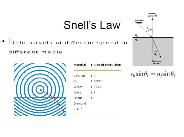
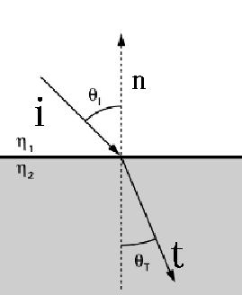
30 Snell s Law When light passes through a boundary between two materials of different density (air and water, for example), the light s direction changes. The direction follows Snell s Law We can do environment mapping using the refracted vector t
31
32 Refractive Environment Mapping Just use the refraction vector after the first hit as the index to the environment map Costly to compute the second refraction vector Better use cubic mapping - Why?
33 Summary Environment mapping is a quick way to simulate the effect of reflecting the world at the surface of a glossy object Practical approaches are the cubic mapping and the sphere mapping Can also be applied for simulating refraction
34 Today Environment Mapping Introduction Cubic mapping Sphere mapping refractive mapping Mirroring Introduction reflection first stencil buffer reflection last
35 Mirroring (Flat Mirrors) : Background Basic idea: Drawing a scene with mirrors Mirrors reflect the world A scene with a mirror can be drawn by rendering the world twice original scene, and reflected scene
36 Mirroring (Flat Mirrors) : Background (2) Simply rendering the scene twice can result in problems The flipped world may appear at area outside the mirror area Unless the mirrored world is hidden by the real world We can avoid such problems using the stencil buffer
37 Reflecting Objects Wall Mirror If the mirror passes through the origin, and is aligned with a coordinate axis, then just negate appropriate coordinate For example, if a reflection plane has a normal n= (0,1,0) and passes the origin, the reflected vertices can be obtained by scaling matrix S(1,-1,1)
38 Reflecting Objects (2) What if the mirror is not on a plane that passes the origin? How do we compute the mirrored world? First, we need to compute the location of objects relative to the mirror
39
40 Reflecting Objects (3) To know the positions of objects with respect to the mirror coordinate, we multiply a transformation matrix from the mirror to the world coordinate to their positions in the world coordinate
41 Reflecting Objects (4) For finding out the flipped location in the mirror coordinate, we multiply the mirroring matrix
42 Reflecting Objects (4) Now we want to know where the flipped points are with respect to the world origin We can multiply the transformation matrix to move from the origin to the mirror to x to know where it is with respect to O
43 Reflecting Objects (5) Altogether

44 Reflection Example The color buffer after the final pass
45 Drawing the mirrored world Two ways to do it: 1. Draw the mirrored world first, then the real world Only using the depth (Z) buffer Does not work in some cases 2. Draw the real-world first, and then the mirrored world Requires using a stencil buffer
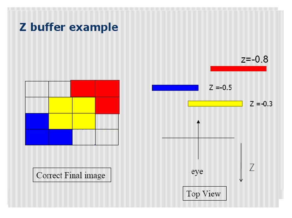
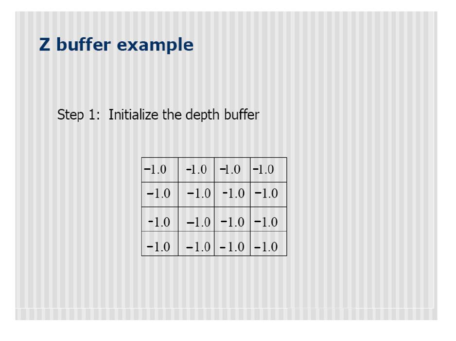
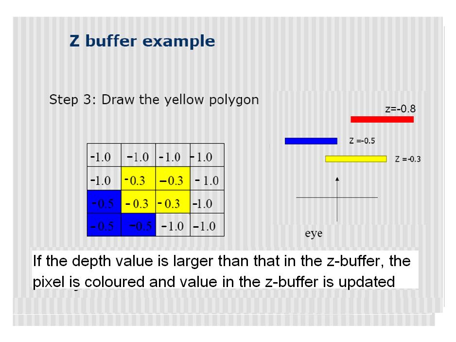
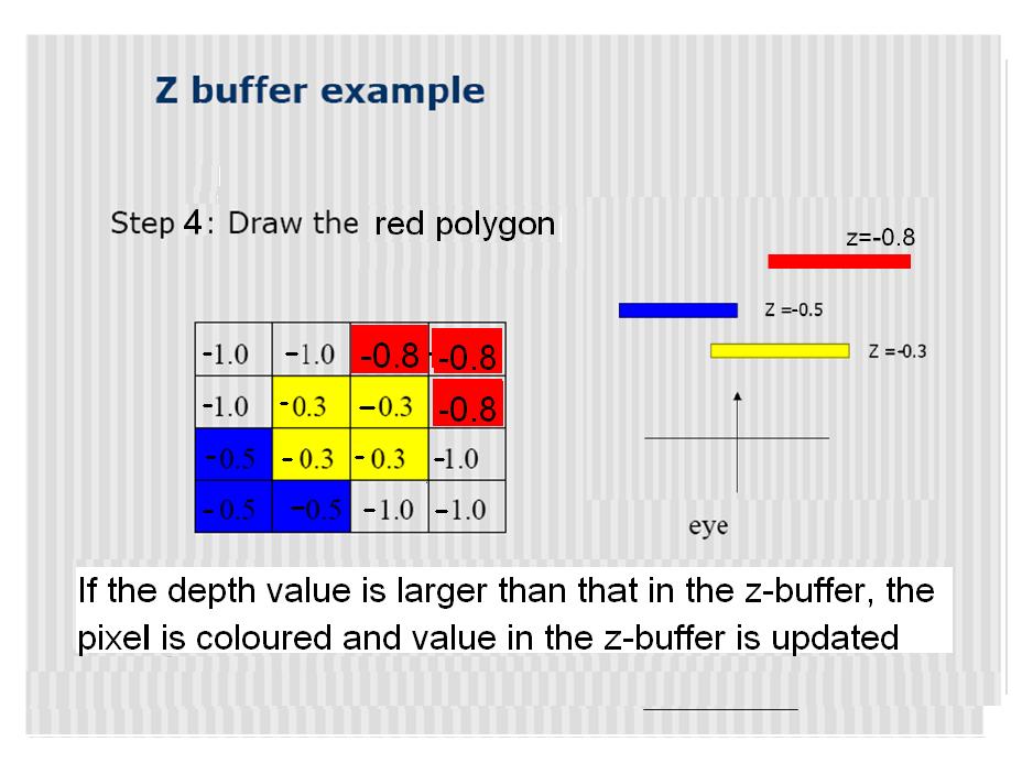
46 Z-buffer One method of hidden surface removal Basic Z-buffer idea: For every input polygon For every pixel in the polygon interior, calculate its corresponding z value. Compare the depth value with the closest value from a different polygon (largest z) so far Paint the pixel (filling in the color buffer) with the color of the polygon if it is closer
47
48

49
50
51
52 Rendering Reflected First (Using the depth buffer(z-buffer)) First pass: Render the reflected scene without mirror, depth test on Second pass: Disable the color buffer, and render the mirror polygon (to not draw over the reflected scene, but setting the Z-buffer on) Now the Z buffer of the mirror region is set to the mirror s surface Third Pass: Enable the color buffer again Render the original scene, without the mirror Depth buffer stops from writing over things in mirror
53 Reflected Scene First (issues) Objects behind the mirror cause problems: The reflected area outside the mirror region is just overwritten by the objects in the front unless there is a wall, they will remain visible Doesn t do: Reflections of mirrors in mirrors (recursive reflections) Multiple mirrors in one scene (that aren t seen in each other)

54 Using the Stencil Buffer to Created Scenes with Mirrors The stencil buffer can help to stop drawing outside the mirror region
55 We need to use the Stencil Buffer The stencil buffer acts like a paint stencil - it lets some fragments through but not others It stores multi-bit values You specify two things: The test that controls which fragments get through The operations to perform on the buffer when the test passes or fails
56 Reflection Example mirror
57 Normal first, reflected area next First pass: Render the scene without the mirror For each mirror Second pass: Clear the stencil, disable the write to the colour buffer, render the mirror, setting the stencil to 1 if the depth test passes Third pass: Clear the depth buffer with the stencil active, passing things inside the mirror only Reflect the world and draw using the stencil test. Only things seen in the mirror will be drawn Combine it with the scene made during the first pass The stencil buffer after the second pass Rendering the mirrored scene into the stencil active area

58 Multiple mirrors Can manage multiple mirrors Render normal view, then do other passes for each mirror A recursive formulation exists for mirrors that see other mirrors After rendering the reflected area inside the mirror surface, render the mirrors inside the mirror surface, and so on
59 Conclusion and Summary Environment mapping cubic mapping spherical mapping refraction mapping Mirroring Flipping the world Zbuffer Stencil buffer
60 Readings Foley Real-time Rendering 2, Chapter 5.7, 6.10 Reference
Computer Graphics. Shadows
 Computer Graphics Lecture 10 Shadows Taku Komura Today Shadows Overview Projective shadows Shadow texture Shadow volume Shadow map Soft shadows Why Shadows? Shadows tell us about the relative locations
COMP environment mapping Mar. 12, r = 2n(n v) v
 v") Rendering mirror surfaces The next texture mapping method assumes we have a mirror surface, or at least a reflectance function that contains a mirror component. Examples might be a car window or hood,
Rendering mirror surfaces The next texture mapping method assumes we have a mirror surface, or at least a reflectance function that contains a mirror component. Examples might be a car window or hood,
Computer Graphics. Lecture 9 Hidden Surface Removal. Taku Komura
 Computer Graphics Lecture 9 Hidden Surface Removal Taku Komura 1 Why Hidden Surface Removal? A correct rendering requires correct visibility calculations When multiple opaque polygons cover the same screen
Lecture 17: Recursive Ray Tracing. Where is the way where light dwelleth? Job 38:19
 Lecture 17: Recursive Ray Tracing Where is the way where light dwelleth? Job 38:19 1. Raster Graphics Typical graphics terminals today are raster displays. A raster display renders a picture scan line
Computer Graphics 10 - Shadows
 Computer Graphics 10 - Shadows Tom Thorne Slides courtesy of Taku Komura www.inf.ed.ac.uk/teaching/courses/cg Overview Shadows Overview Projective shadows Shadow textures Shadow volume Shadow map Soft
Hidden surface removal. Computer Graphics
 Lecture Hidden Surface Removal and Rasterization Taku Komura Hidden surface removal Drawing polygonal faces on screen consumes CPU cycles Illumination We cannot see every surface in scene We don t want
Consider a partially transparent object that is illuminated with two lights, one visible from each side of the object. Start with a ray from the eye
 Ray Tracing What was the rendering equation? Motivate & list the terms. Relate the rendering equation to forward ray tracing. Why is forward ray tracing not good for image formation? What is the difference
Computer Graphics. Lecture 13. Global Illumination 1: Ray Tracing and Radiosity. Taku Komura
 Computer Graphics Lecture 13 Global Illumination 1: Ray Tracing and Radiosity Taku Komura 1 Rendering techniques Can be classified as Local Illumination techniques Global Illumination techniques Local
Ray Tracing: Special Topics CSCI 4239/5239 Advanced Computer Graphics Spring 2018
 Ray Tracing: Special Topics CSCI 4239/5239 Advanced Computer Graphics Spring 2018 Theoretical foundations Ray Tracing from the Ground Up Chapters 13-15 Bidirectional Reflectance Distribution Function BRDF
Computer Graphics. Lecture 14 Bump-mapping, Global Illumination (1)
") Computer Graphics Lecture 14 Bump-mapping, Global Illumination (1) Today - Bump mapping - Displacement mapping - Global Illumination Radiosity Bump Mapping - A method to increase the realism of 3D objects
Computer Graphics Lecture 14 Bump-mapping, Global Illumination (1) Today - Bump mapping - Displacement mapping - Global Illumination Radiosity Bump Mapping - A method to increase the realism of 3D objects
Recollection. Models Pixels. Model transformation Viewport transformation Clipping Rasterization Texturing + Lights & shadows
 Recollection Models Pixels Model transformation Viewport transformation Clipping Rasterization Texturing + Lights & shadows Can be computed in different stages 1 So far we came to Geometry model 3 Surface
CMSC427 Advanced shading getting global illumination by local methods. Credit: slides Prof. Zwicker
 CMSC427 Advanced shading getting global illumination by local methods Credit: slides Prof. Zwicker Topics Shadows Environment maps Reflection mapping Irradiance environment maps Ambient occlusion Reflection
Computer Graphics Lecture 11
 1 / 14 Computer Graphics Lecture 11 Dr. Marc Eduard Frîncu West University of Timisoara May 15th 2012 2 / 14 Outline 1 Introduction 2 Transparency 3 Reflection 4 Recap 3 / 14 Introduction light = local
lecture 18 - ray tracing - environment mapping - refraction
 lecture 18 - ray tracing - environment mapping - refraction Recall Ray Casting (lectures 7, 8) for each pixel (x,y) { cast a ray through that pixel into the scene, and find the closest surface along the
So far, we have considered only local models of illumination; they only account for incident light coming directly from the light sources.
 11 11.1 Basics So far, we have considered only local models of illumination; they only account for incident light coming directly from the light sources. Global models include incident light that arrives
Lighting and Shading
 Lighting and Shading Today: Local Illumination Solving the rendering equation is too expensive First do local illumination Then hack in reflections and shadows Local Shading: Notation light intensity in,
Recall: Indexing into Cube Map
 Recall: Indexing into Cube Map Compute R = 2(N V)N-V Object at origin Use largest magnitude component of R to determine face of cube Other 2 components give texture coordinates V R Cube Map Layout Example
Real Time Reflections Han-Wei Shen
 Real Time Reflections Han-Wei Shen Reflections One of the most noticeable effect of inter-object lighting Direct calculation of the physics (ray tracing) is too expensive Our focus is to capture the most
Models and Architectures
 Models and Architectures Objectives Learn the basic design of a graphics system Introduce graphics pipeline architecture Examine software components for an interactive graphics system 1 Image Formation
Models and Architectures. Ed Angel Professor of Computer Science, Electrical and Computer Engineering, and Media Arts University of New Mexico
 Models and Architectures Ed Angel Professor of Computer Science, Electrical and Computer Engineering, and Media Arts University of New Mexico 1 Objectives Learn the basic design of a graphics system Introduce
CS 354R: Computer Game Technology
 CS 354R: Computer Game Technology Texture and Environment Maps Fall 2018 Texture Mapping Problem: colors, normals, etc. are only specified at vertices How do we add detail between vertices without incurring
Homework #2 and #3 Due Friday, October 12 th and Friday, October 19 th
 Homework #2 and #3 Due Friday, October 12 th and Friday, October 19 th 1. a. Show that the following sequences commute: i. A rotation and a uniform scaling ii. Two rotations about the same axis iii. Two
Topic 12: Texture Mapping. Motivation Sources of texture Texture coordinates Bump mapping, mip-mapping & env mapping
 Topic 12: Texture Mapping Motivation Sources of texture Texture coordinates Bump mapping, mip-mapping & env mapping Texture sources: Photographs Texture sources: Procedural Texture sources: Solid textures
Topic 11: Texture Mapping 11/13/2017. Texture sources: Solid textures. Texture sources: Synthesized
 Topic 11: Texture Mapping Motivation Sources of texture Texture coordinates Bump mapping, mip mapping & env mapping Texture sources: Photographs Texture sources: Procedural Texture sources: Solid textures
Computer Graphics. Lecture 10. Global Illumination 1: Ray Tracing and Radiosity. Taku Komura 12/03/15
 Computer Graphics Lecture 10 Global Illumination 1: Ray Tracing and Radiosity Taku Komura 1 Rendering techniques Can be classified as Local Illumination techniques Global Illumination techniques Local
Topic 11: Texture Mapping 10/21/2015. Photographs. Solid textures. Procedural
 Topic 11: Texture Mapping Motivation Sources of texture Texture coordinates Bump mapping, mip mapping & env mapping Topic 11: Photographs Texture Mapping Motivation Sources of texture Texture coordinates
Ray tracing. Computer Graphics COMP 770 (236) Spring Instructor: Brandon Lloyd 3/19/07 1
 Spring Instructor: Brandon Lloyd 3/19/07 1") Ray tracing Computer Graphics COMP 770 (236) Spring 2007 Instructor: Brandon Lloyd 3/19/07 1 From last time Hidden surface removal Painter s algorithm Clipping algorithms Area subdivision BSP trees Z-Buffer
Ray tracing Computer Graphics COMP 770 (236) Spring 2007 Instructor: Brandon Lloyd 3/19/07 1 From last time Hidden surface removal Painter s algorithm Clipping algorithms Area subdivision BSP trees Z-Buffer
Introduction to Visualization and Computer Graphics
 Introduction to Visualization and Computer Graphics DH2320, Fall 2015 Prof. Dr. Tino Weinkauf Introduction to Visualization and Computer Graphics Visibility Shading 3D Rendering Geometric Model Color Perspective
Homework #2. Shading, Ray Tracing, and Texture Mapping
 Computer Graphics Prof. Brian Curless CSE 457 Spring 2000 Homework #2 Shading, Ray Tracing, and Texture Mapping Prepared by: Doug Johnson, Maya Widyasari, and Brian Curless Assigned: Monday, May 8, 2000
Introduction to Computer Graphics with WebGL
 Introduction to Computer Graphics with WebGL Ed Angel Professor Emeritus of Computer Science Founding Director, Arts, Research, Technology and Science Laboratory University of New Mexico Models and Architectures
Point Cloud Filtering using Ray Casting by Eric Jensen 2012 The Basic Methodology
 Point Cloud Filtering using Ray Casting by Eric Jensen 01 The Basic Methodology Ray tracing in standard graphics study is a method of following the path of a photon from the light source to the camera,
Rendering. Converting a 3D scene to a 2D image. Camera. Light. Rendering. View Plane
 Rendering Pipeline Rendering Converting a 3D scene to a 2D image Rendering Light Camera 3D Model View Plane Rendering Converting a 3D scene to a 2D image Basic rendering tasks: Modeling: creating the world
Volume Shadows Tutorial Nuclear / the Lab
 Volume Shadows Tutorial Nuclear / the Lab Introduction As you probably know the most popular rendering technique, when speed is more important than quality (i.e. realtime rendering), is polygon rasterization.
INFOGR Computer Graphics. J. Bikker - April-July Lecture 10: Ground Truth. Welcome!
 INFOGR Computer Graphics J. Bikker - April-July 2015 - Lecture 10: Ground Truth Welcome! Today s Agenda: Limitations of Whitted-style Ray Tracing Monte Carlo Path Tracing INFOGR Lecture 10 Ground Truth
COMP371 COMPUTER GRAPHICS
 COMP371 COMPUTER GRAPHICS SESSION 15 RAY TRACING 1 Announcements Programming Assignment 3 out today - overview @ end of the class Ray Tracing 2 Lecture Overview Review of last class Ray Tracing 3 Local
Topics and things to know about them:
 Practice Final CMSC 427 Distributed Tuesday, December 11, 2007 Review Session, Monday, December 17, 5:00pm, 4424 AV Williams Final: 10:30 AM Wednesday, December 19, 2007 General Guidelines: The final will
Visibility: Z Buffering
 University of British Columbia CPSC 414 Computer Graphics Visibility: Z Buffering Week 1, Mon 3 Nov 23 Tamara Munzner 1 Poll how far are people on project 2? preferences for Plan A: status quo P2 stays
CS3500 Computer Graphics Module: Lighting and Shading
 Computer Graphics Module: Lighting and Shading P. J. Narayanan Spring 2009 We know which pixels of the frame buffer belongs to which object after visibility and scan conversion. What colour to give to
CS 488. More Shading and Illumination. Luc RENAMBOT
 CS 488 More Shading and Illumination Luc RENAMBOT 1 Illumination No Lighting Ambient model Light sources Diffuse reflection Specular reflection Model: ambient + specular + diffuse Shading: flat, gouraud,
Computer Graphics Shadow Algorithms
 Computer Graphics Shadow Algorithms Computer Graphics Computer Science Department University of Freiburg WS 11 Outline introduction projection shadows shadow maps shadow volumes conclusion Motivation shadows
9. Illumination and Shading
 9. Illumination and Shading Approaches for visual realism: - Remove hidden surfaces - Shade visible surfaces and reproduce shadows - Reproduce surface properties Texture Degree of transparency Roughness,
Welcome to: Physics I. I m Dr Alex Pettitt, and I ll be your guide!
 Welcome to: Physics I I m Dr Alex Pettitt, and I ll be your guide! Physics I: x Mirrors and lenses Lecture 13: 6-11-2018 Last lecture: Reflection & Refraction Reflection: Light ray hits surface Ray moves
Recursive Ray Tracing. Ron Goldman Department of Computer Science Rice University
 Recursive Ray Tracing Ron Goldman Department of Computer Science Rice University Setup 1. Eye Point 2. Viewing Screen 3. Light Sources 4. Objects in Scene a. Reflectivity b. Transparency c. Index of Refraction
03 RENDERING PART TWO
 03 RENDERING PART TWO WHAT WE HAVE SO FAR: GEOMETRY AFTER TRANSFORMATION AND SOME BASIC CLIPPING / CULLING TEXTURES AND MAPPING MATERIAL VISUALLY DISTINGUISHES 2 OBJECTS WITH IDENTICAL GEOMETRY FOR NOW,
TSBK03 Screen-Space Ambient Occlusion
 TSBK03 Screen-Space Ambient Occlusion Joakim Gebart, Jimmy Liikala December 15, 2013 Contents 1 Abstract 1 2 History 2 2.1 Crysis method..................................... 2 3 Chosen method 2 3.1 Algorithm
Real-Time Shadows. Last Time? Today. Why are Shadows Important? Shadows as a Depth Cue. For Intuition about Scene Lighting
 Last Time? Real-Time Shadows Today Why are Shadows Important? Shadows & Soft Shadows in Ray Tracing Planar Shadows Projective Texture Shadows Shadow Maps Shadow Volumes Why are Shadows Important? Depth
Pipeline Operations. CS 4620 Lecture 10
 Pipeline Operations CS 4620 Lecture 10 2008 Steve Marschner 1 Hidden surface elimination Goal is to figure out which color to make the pixels based on what s in front of what. Hidden surface elimination
Computer Graphics. Si Lu. Fall uter_graphics.htm 11/22/2017
 Computer Graphics Si Lu Fall 2017 http://web.cecs.pdx.edu/~lusi/cs447/cs447_547_comp uter_graphics.htm 11/22/2017 Last time o Splines 2 Today o Raytracing o Final Exam: 14:00-15:30, Novermber 29, 2017
The Traditional Graphics Pipeline
 Last Time? The Traditional Graphics Pipeline Participating Media Measuring BRDFs 3D Digitizing & Scattering BSSRDFs Monte Carlo Simulation Dipole Approximation Today Ray Casting / Tracing Advantages? Ray
Chapter 32 Light: Reflection and Refraction. Copyright 2009 Pearson Education, Inc.
 Chapter 32 Light: Reflection and Refraction Units of Chapter 32 The Ray Model of Light Reflection; Image Formation by a Plane Mirror Formation of Images by Spherical Mirrors Index of Refraction Refraction:
For Intuition about Scene Lighting. Today. Limitations of Planar Shadows. Cast Shadows on Planar Surfaces. Shadow/View Duality.
 Last Time Modeling Transformations Illumination (Shading) Real-Time Shadows Viewing Transformation (Perspective / Orthographic) Clipping Projection (to Screen Space) Graphics Pipeline Clipping Rasterization
Ray Tracing. Outline. Ray Tracing: History
 Foundations of omputer Graphics Online Lecture 9: Ray Tracing 1 History and asic Ray asting Ravi Ramamoorthi Effects needed for Realism (Soft) Shadows Reflections (Mirrors and Glossy) Transparency (Water,
COMPLETION OF Z-buffer Graphics Pipeline
 Z-buffer algorithm for each polygon in model project vertices of polygon onto viewing plane for each pixel inside the projected polygon calculate pixel colour calculate pixel z-value compare pixel z-value
The Traditional Graphics Pipeline
 Last Time? The Traditional Graphics Pipeline Reading for Today A Practical Model for Subsurface Light Transport, Jensen, Marschner, Levoy, & Hanrahan, SIGGRAPH 2001 Participating Media Measuring BRDFs
Computer Graphics. Bing-Yu Chen National Taiwan University The University of Tokyo
 Computer Graphics Bing-Yu Chen National Taiwan University The University of Tokyo Hidden-Surface Removal Back-Face Culling The Depth-Sort Algorithm Binary Space-Partitioning Trees The z-buffer Algorithm
SNC2D PHYSICS 4/27/2013. LIGHT & GEOMETRIC OPTICS L Light Rays & Reflection (P ) Light Rays & Reflection. The Ray Model of Light
 Light Rays & Reflection. The Ray Model of Light") SNC2D PHYSICS LIGHT & GEOMETRIC OPTICS L Light Rays & Reflection (P.402-409) Light Rays & Reflection A driver adjusts her rearview mirror. The mirror allows her to see the cars behind her. Mirrors help
SNC2D PHYSICS LIGHT & GEOMETRIC OPTICS L Light Rays & Reflection (P.402-409) Light Rays & Reflection A driver adjusts her rearview mirror. The mirror allows her to see the cars behind her. Mirrors help
CS 325 Computer Graphics
 CS 325 Computer Graphics 04 / 02 / 2012 Instructor: Michael Eckmann Today s Topics Questions? Comments? Illumination modelling Ambient, Diffuse, Specular Reflection Surface Rendering / Shading models Flat
Phys102 Lecture 21/22 Light: Reflection and Refraction
 Phys102 Lecture 21/22 Light: Reflection and Refraction Key Points The Ray Model of Light Reflection and Mirrors Refraction, Snell s Law Total internal Reflection References 23-1,2,3,4,5,6. The Ray Model
Last Time. Why are Shadows Important? Today. Graphics Pipeline. Clipping. Rasterization. Why are Shadows Important?
 Last Time Modeling Transformations Illumination (Shading) Real-Time Shadows Viewing Transformation (Perspective / Orthographic) Clipping Projection (to Screen Space) Graphics Pipeline Clipping Rasterization
COMP30019 Graphics and Interaction Ray Tracing
 COMP30019 Graphics and Interaction Ray Tracing Department of Computer Science and Software Engineering The Lecture outline Ray tracing Recursive Ray Tracing Binary Space Partition (BSP) Trees Refraction
REFLECTION & REFRACTION
 REFLECTION & REFRACTION OBJECTIVE: To study and verify the laws of reflection and refraction using a plane mirror and a glass block. To see the virtual images that can be formed by the reflection and refraction
Advanced Shading I: Shadow Rasterization Techniques
 Advanced Shading I: Shadow Rasterization Techniques Shadow Terminology umbra: light totally blocked penumbra: light partially blocked occluder: object blocking light Shadow Terminology umbra: light totally
Computergrafik. Matthias Zwicker. Herbst 2010
 Computergrafik Matthias Zwicker Universität Bern Herbst 2010 Today Bump mapping Shadows Shadow mapping Shadow mapping in OpenGL Bump mapping Surface detail is often the result of small perturbations in
Lecture 11: Ray tracing (cont.)
") Interactive Computer Graphics Ray tracing - Summary Lecture 11: Ray tracing (cont.) Graphics Lecture 10: Slide 1 Some slides adopted from H. Pfister, Harvard Graphics Lecture 10: Slide 2 Ray tracing -
Interactive Computer Graphics Ray tracing - Summary Lecture 11: Ray tracing (cont.) Graphics Lecture 10: Slide 1 Some slides adopted from H. Pfister, Harvard Graphics Lecture 10: Slide 2 Ray tracing -
Z-Buffer hold pixel's distance from camera. Z buffer
 Z-Buffer hold pixel's distance from camera Z buffer Frustrum Culling and Z-buffering insufficient Given a large enough set of polygons, no matter how fast the graphics card, sending it too many hidden
Effects needed for Realism. Computer Graphics (Fall 2008) Ray Tracing. Ray Tracing: History. Outline
 Ray Tracing. Ray Tracing: History. Outline") Computer Graphics (Fall 2008) COMS 4160, Lecture 15: Ray Tracing http://www.cs.columbia.edu/~cs4160 Effects needed for Realism (Soft) Shadows Reflections (Mirrors and Glossy) Transparency (Water, Glass)
Computer Graphics (Fall 2008) COMS 4160, Lecture 15: Ray Tracing http://www.cs.columbia.edu/~cs4160 Effects needed for Realism (Soft) Shadows Reflections (Mirrors and Glossy) Transparency (Water, Glass)
Real-Time Shadows. Last Time? Textures can Alias. Schedule. Questions? Quiz 1: Tuesday October 26 th, in class (1 week from today!
 Last Time? Real-Time Shadows Perspective-Correct Interpolation Texture Coordinates Procedural Solid Textures Other Mapping Bump Displacement Environment Lighting Textures can Alias Aliasing is the under-sampling
Effects needed for Realism. Ray Tracing. Ray Tracing: History. Outline. Foundations of Computer Graphics (Spring 2012)
") Foundations of omputer Graphics (Spring 202) S 84, Lecture 5: Ray Tracing http://inst.eecs.berkeley.edu/~cs84 Effects needed for Realism (Soft) Shadows Reflections (Mirrors and Glossy) Transparency (Water,
Foundations of omputer Graphics (Spring 202) S 84, Lecture 5: Ray Tracing http://inst.eecs.berkeley.edu/~cs84 Effects needed for Realism (Soft) Shadows Reflections (Mirrors and Glossy) Transparency (Water,
Shadows in the graphics pipeline
 Shadows in the graphics pipeline Steve Marschner Cornell University CS 569 Spring 2008, 19 February There are a number of visual cues that help let the viewer know about the 3D relationships between objects
Chapter 7: Geometrical Optics
 Chapter 7: Geometrical Optics 7. Reflection at a Spherical Surface L.O 7.. State laws of reflection Laws of reflection state: L.O The incident ray, the reflected ray and the normal all lie in the same
Lecture 18: Primer on Ray Tracing Techniques
 Lecture 18: Primer on Ray Tracing Techniques 6.172: Performance Engineering of Software Systems Joshua Slocum November 16, 2010 A Little Background Image rendering technique Simulate rays of light - ray
Chapter 7: Geometrical Optics. The branch of physics which studies the properties of light using the ray model of light.
 Chapter 7: Geometrical Optics The branch of physics which studies the properties of light using the ray model of light. Overview Geometrical Optics Spherical Mirror Refraction Thin Lens f u v r and f 2
Computer Graphics (CS 543) Lecture 13b Ray Tracing (Part 1) Prof Emmanuel Agu. Computer Science Dept. Worcester Polytechnic Institute (WPI)
 Lecture 13b Ray Tracing (Part 1) Prof Emmanuel Agu. Computer Science Dept. Worcester Polytechnic Institute (WPI)") Computer Graphics (CS 543) Lecture 13b Ray Tracing (Part 1) Prof Emmanuel Agu Computer Science Dept. Worcester Polytechnic Institute (WPI) Raytracing Global illumination-based rendering method Simulates
Computer Graphics (CS 543) Lecture 13b Ray Tracing (Part 1) Prof Emmanuel Agu Computer Science Dept. Worcester Polytechnic Institute (WPI) Raytracing Global illumination-based rendering method Simulates
Ray-Tracing. Misha Kazhdan
 Ray-Tracing Misha Kazhdan Ray-Tracing In graphics, we often represent the surface of a 3D shape by a set of triangles. Goal: Ray-Tracing Take a collection of triangles representing a 3D scene and render
Shading, Advanced Rendering. Week 7, Wed Feb 28
 University of British Columbia CPSC 314 Computer Graphics Jan-Apr 2007 Tamara Munzner Shading, Advanced Rendering Week 7, Wed Feb 28 http://www.ugrad.cs.ubc.ca/~cs314/vjan2007 Reading for Today and Tomorrow
Graphics for VEs. Ruth Aylett
 Graphics for VEs Ruth Aylett Overview VE Software Graphics for VEs The graphics pipeline Projections Lighting Shading VR software Two main types of software used: off-line authoring or modelling packages
Pipeline Operations. CS 4620 Lecture 14
 Pipeline Operations CS 4620 Lecture 14 2014 Steve Marschner 1 Pipeline you are here APPLICATION COMMAND STREAM 3D transformations; shading VERTEX PROCESSING TRANSFORMED GEOMETRY conversion of primitives
Intro to Ray-Tracing & Ray-Surface Acceleration
 Lecture 12 & 13: Intro to Ray-Tracing & Ray-Surface Acceleration Computer Graphics and Imaging UC Berkeley Course Roadmap Rasterization Pipeline Core Concepts Sampling Antialiasing Transforms Geometric
Ray Tracing Basics I. Computer Graphics as Virtual Photography. camera (captures light) real scene. photo. Photographic print. Photography: processing
 real scene. photo. Photographic print. Photography: processing") Ray Tracing Basics I Computer Graphics as Virtual Photography Photography: real scene camera (captures light) photo processing Photographic print processing Computer Graphics: 3D models camera model (focuses
Ray Tracing Basics I Computer Graphics as Virtual Photography Photography: real scene camera (captures light) photo processing Photographic print processing Computer Graphics: 3D models camera model (focuses
OpenGl Pipeline. triangles, lines, points, images. Per-vertex ops. Primitive assembly. Texturing. Rasterization. Per-fragment ops.
 OpenGl Pipeline Individual Vertices Transformed Vertices Commands Processor Per-vertex ops Primitive assembly triangles, lines, points, images Primitives Fragments Rasterization Texturing Per-fragment
Complex Features on a Surface. CITS4241 Visualisation Lectures 22 & 23. Texture mapping techniques. Texture mapping techniques
 Complex Features on a Surface CITS4241 Visualisation Lectures 22 & 23 Texture Mapping Rendering all surfaces as blocks of colour Not very realistic result! Even with shading Many objects have detailed
When light strikes an object there are different ways it can be affected. Light can be
 When light strikes an object there are different ways it can be affected. Light can be transmitted, reflected, refracted, and absorbed, It depends on the type of matter that it strikes. For example light
Lighting. Figure 10.1
 We have learned to build three-dimensional graphical models and to display them. However, if you render one of our models, you might be disappointed to see images that look flat and thus fail to show the
Graphics and Interaction Rendering pipeline & object modelling
 433-324 Graphics and Interaction Rendering pipeline & object modelling Department of Computer Science and Software Engineering The Lecture outline Introduction to Modelling Polygonal geometry The rendering
Computing Visibility. Backface Culling for General Visibility. One More Trick with Planes. BSP Trees Ray Casting Depth Buffering Quiz
 Computing Visibility BSP Trees Ray Casting Depth Buffering Quiz Power of Plane Equations We ve gotten a lot of mileage out of one simple equation. Basis for D outcode-clipping Basis for plane-at-a-time
Image-Based Lighting. Inserting Synthetic Objects
 Image-Based Lighting 15-463: Rendering and Image Processing Alexei Efros with a lot of slides donated by Paul Debevec Inserting Synthetic Objects Why does this look so bad? Wrong camera orientation Wrong
Real-Time Shadows. Computer Graphics. MIT EECS Durand 1
 Real-Time Shadows Computer Graphics MIT EECS 6.837 Durand 1 Why are Shadows Important? Depth cue Scene Lighting Realism Contact points 2 Shadows as a Depth Cue source unknown. All rights reserved. This
The Traditional Graphics Pipeline
 Final Projects Proposals due Thursday 4/8 Proposed project summary At least 3 related papers (read & summarized) Description of series of test cases Timeline & initial task assignment The Traditional Graphics
03 Vector Graphics. Multimedia Systems. 2D and 3D Graphics, Transformations
 Multimedia Systems 03 Vector Graphics 2D and 3D Graphics, Transformations Imran Ihsan Assistant Professor, Department of Computer Science Air University, Islamabad, Pakistan www.imranihsan.com Lectures
Local Illumination. CMPT 361 Introduction to Computer Graphics Torsten Möller. Machiraju/Zhang/Möller
 Local Illumination CMPT 361 Introduction to Computer Graphics Torsten Möller Graphics Pipeline Hardware Modelling Transform Visibility Illumination + Shading Perception, Interaction Color Texture/ Realism
Rendering Algorithms: Real-time indirect illumination. Spring 2010 Matthias Zwicker
 Rendering Algorithms: Real-time indirect illumination Spring 2010 Matthias Zwicker Today Real-time indirect illumination Ray tracing vs. Rasterization Screen space techniques Visibility & shadows Instant
CS 4620 Program 3: Pipeline
 CS 4620 Program 3: Pipeline out: Wednesday 14 October 2009 due: Friday 30 October 2009 1 Introduction In this assignment, you will implement several types of shading in a simple software graphics pipeline.
Today s Topic: Refraction / Snell s Law
 Today s Topic: Refraction / Snell s Law Learning Goal: Students will be able to calculate the angle of reflection of a bent light wave. Take out your notes from yesterday as we learn about Snell s Law.
Experiment 3: Reflection
 Model No. OS-8515C Experiment 3: Reflection Experiment 3: Reflection Required Equipment from Basic Optics System Light Source Mirror from Ray Optics Kit Other Required Equipment Drawing compass Protractor
Ray Tracing. CSCI 420 Computer Graphics Lecture 15. Ray Casting Shadow Rays Reflection and Transmission [Ch ]
![Ray Tracing. CSCI 420 Computer Graphics Lecture 15. Ray Casting Shadow Rays Reflection and Transmission [Ch ]](/thumbs/78/78594982.jpg "Ray Tracing. CSCI 420 Computer Graphics Lecture 15. Ray Casting Shadow Rays Reflection and Transmission [Ch ]") CSCI 420 Computer Graphics Lecture 15 Ray Tracing Ray Casting Shadow Rays Reflection and Transmission [Ch. 13.2-13.3] Jernej Barbic University of Southern California 1 Local Illumination Object illuminations
CSCI 420 Computer Graphics Lecture 15 Ray Tracing Ray Casting Shadow Rays Reflection and Transmission [Ch. 13.2-13.3] Jernej Barbic University of Southern California 1 Local Illumination Object illuminations
Reflection and Refraction
 Reflection and Refraction Lecture #21 Tuesday, ovember 18, 2014 How about Interreflections! ote reflections! Granite tabletop! Visible on base! Also on handle This is a featured picture on the English
Ray Tracing. Cornell CS4620/5620 Fall 2012 Lecture Kavita Bala 1 (with previous instructors James/Marschner)
") CS4620/5620: Lecture 37 Ray Tracing 1 Announcements Review session Tuesday 7-9, Phillips 101 Posted notes on slerp and perspective-correct texturing Prelim on Thu in B17 at 7:30pm 2 Basic ray tracing Basic
CS4620/5620: Lecture 37 Ray Tracing 1 Announcements Review session Tuesday 7-9, Phillips 101 Posted notes on slerp and perspective-correct texturing Prelim on Thu in B17 at 7:30pm 2 Basic ray tracing Basic
CS130 : Computer Graphics Lecture 8: Lighting and Shading. Tamar Shinar Computer Science & Engineering UC Riverside
 CS130 : Computer Graphics Lecture 8: Lighting and Shading Tamar Shinar Computer Science & Engineering UC Riverside Why we need shading Suppose we build a model of a sphere using many polygons and color
Optics INTRODUCTION DISCUSSION OF PRINCIPLES. Reflection by a Plane Mirror
 Optics INTRODUCTION Geometric optics is one of the oldest branches of physics, dealing with the laws of reflection and refraction. Reflection takes place on the surface of an object, and refraction occurs
Lecture 19: All Together with Refraction
 Lecture 19: All Together with Refraction December 1, 2016 12/1/16 CSU CS410 Fall 2016, Ross Beveridge & Bruce Draper 1 How about Interreflections? Note reflections Granite tabletop Visible on base Also