SAP2000, ETABS, SAFE and Revit 2018 Data Exchange Documentation
|
|
|
- May Stokes
- 6 years ago
- Views:
Transcription
1 SAP2000, ETABS, SAFE and Revit 2018 Data Exchange Documentation ISO XRV080317M1 Rev. 0 Version Proudly developed in the United States of America August 2017
2 Copyright Copyright Computers and Structures, Inc., 2017 All rights reserved. The CSI Logo, ETABS, SAP2000, SAFE are registered trademarks of Computers and Structures, Inc. Watch & Learn TM is a trademark of Computers and Structures, Inc. Revit is a registered trademark of Autodesk. The computer program ETABS, SAP2000, and SAFE and all associated documentation are proprietary and copyrighted products. Worldwide rights of ownership rest with Computers and Structures, Inc. Unlicensed use of the program or reproduction of the documentation in any form, without prior written authorization from Computers and Structures, Inc., is explicitly prohibited. No part of this publication may be reproduced or distributed in any form or by any means, or stored in a database or retrieval system, without the prior explicit written permission of the publisher. Further information and copies of this documentation may be obtained from: Computers and Structures, Inc. info@csiamerica.com (for general information) support@csiamerica.com (for technical support) 2
3 DISCLAIMER CONSIDERABLE TIME, EFFORT AND EXPENSE HAVE GONE INTO THE DEVELOPMENT AND TESTING OF THIS SOFTWARE. HOWEVER, THE USER ACCEPTS AND UNDERSTANDS THAT NO WARRANTY IS EXPRESSED OR IMPLIED BY THE DEVELOPERS OR THE DISTRIBUTORS ON THE ACCURACY OR THE RELIABILITY OF THIS PRODUCT. THIS PRODUCT IS A PRACTICAL AND POWERFUL TOOL FOR STRUCTURAL DESIGN. HOWEVER, THE USER MUST EXPLICITLY UNDERSTAND THE BASIC ASSUMPTIONS OF THE SOFTWARE MODELING, ANALYSIS, AND DESIGN ALGORITHMS AND COMPENSATE FOR THE ASPECTS THAT ARE NOT ADDRESSED. THE INFORMATION PRODUCED BY THE SOFTWARE MUST BE CHECKED BY A QUALIFIED AND EXPERIENCED ENGINEER. THE ENGINEER MUST INDEPENDENTLY VERIFY THE RESULTS AND TAKE PROFESSIONAL RESPONSIBILITY FOR THE INFORMATION THAT IS USED. 3
4 Introduction This document describes how to exchange Building Information Modeling (BIM) data between Revit 2018 and ETABS 2015 or later, SAP2000 v17 or greater, and SAFE 2014 or later. This document includes three sections. The first section reviews data exchange between Revit and ETABS. The second section reviews data exchange between Revit and SAP2000. The third section reviews data exchange between Revit and SAFE. Data exchange between Revit and ETABS supports four different workflows: 1) Exporting from Revit to create a new ETABS model. 2) Exporting from Revit to update an existing ETABS model. 3) Importing from ETABS to create a new Revit project. 4) Importing from ETABS to update an existing Revit project. In this case, you may choose to update locations, designs, or both. Data exchange between Revit and SAP2000 supports two different workflows: 1) Exporting from Revit to create a new SAP2000 model. 2) Exporting from Revit to update an existing SAP2000 model. SAP2000 v or later is required. 3) Importing from SAP2000 to create a new Revit project. 4) Importing from SAP2000 to update an existing Revit project. In this case, you may choose to update locations, designs, or both. SAP2000 v or later is required. Data exchange between Revit and SAFE supports four different workflows: 1) Exporting from Revit to create a new SAFE model. 2) Exporting from Revit to update an existing SAFE model. 3) Importing from SAFE to create a new Revit project. 4) Importing from SAFE to update an existing Revit project. In this case, you may choose to only update locations, only update designs, or update both. 4


5 The flow of information is represented in the schematic below: Export from Revit to create a new ETABS, SAP2000 or SAFE model. Export from Revit to update an existing ETABS or SAFE model. Revit Structure ETABS, SAP2000 or SAFE Import from ETABS, SAP2000 or SAFE to create a new Revit project. Import from ETABS, SAP2000 or SAFE to update an existing Revit project. 5
6 Revit and ETABS Data Exchange Data exchange between CSiXRevit and ETABS supports four different workflows: 1) Exporting from Revit to create a new ETABS model. 2) Exporting from Revit to update an existing ETABS model. 3) Importing from ETABS to create a new Revit project. 4) Importing from ETABS to update an existing Revit project. Supported Workflows Exporting from Revit to create a new ETABS model The table below provides an overview of the data imported in ETABS when exporting from Revit to create a new ETABS model: Action Project Element Supported Notes Creation of Grid Lines Story Levels Materials Structural Columns and Structural Framing Transfers geometry, offsets, end releases, and beam and brace alignment points into ETABS. Imports columns based on splice information in ETABS. Steel Column and Framing Family Types Concrete Column and Framing Family Types Walls Wall Family Types Wall Openings Floors Floor Family Types Floor Openings Creates and maps equivalent ETABS frame sections. Makes Auto-Select Lists in ETABS for all families used in the Revit project. Creates and maps equivalent ETABS frame sections. Slanted or warped walls not imported. Creates and maps equivalent ETABS wall sections. Sloped floors with more than four outer corners are projected on a horizontal plane. Creates and maps equivalent ETABS slab and deck sections. 6
7 Footings Point Loads Line Loads Area Loads Load Cases Load Combos Creates fixed joint restraints in ETABS wherever a footing occurs in Revit. Non-uniform area loads not imported. Creates both an ETABS load pattern and load case for each Revit load case. Grids The following Grid attributes are created in ETABS: Grid Name: The same grid name is used in the ETABS grid bubble. Grid Points: The start and end points are used to define the general grid line in ETABS. Curved Grid: The center point, radius, start angle and aperture are used to define the circular grid line in ETABS. Materials The following material attributes are created in ETABS: Material Name: The same name is used in ETABS. Material Type: The Revit material type is used to identify the ETABS material type, namely Concrete, Steel or Other. Young s Modulus: The Young s modulus values from Revit set the ETABS material Young s modulus (E). These three values (for the three different directions) cannot be zero in ETABS. If the first value is zero, then the default ETABS value is used. If any of the remaining two are zero, then the first non-zero value is used. For an isotropic material, the first value is used for all other directions. Poisson s Ratio: Poisson s Ratio values from Revit set the ETABS material Poisson s Ratio (u). These three values (for the three different directions) cannot be zero in ETABS. If the first value is zero, then the default ETABS value is used. If any of the remaining two are zero, then the first non-zero value is used. For an isotropic material, the first value is used for all other directions. Shear Modulus: Shear Modulus value from Revit set the ETABS material Shear Modulus (G). If the Revit material is defined as isotropic, then ETABS calculates this value on the basis of the Young s Modulus and the Poisson s Ratio. In the case of an orthotropic material, these three values (for the three different directions) cannot be zero in ETABS. If the first value is zero, then the default ETABS value is used. If any of the remaining two are zero, then the first non-zero value is used. Thermal Expansion Coefficient: The thermal expansion coefficient from Revit sets the ETABS material thermal expansion coefficient (Alpha). These three values (for the three 7
8 different directions) cannot be zero in ETABS. If the first value is zero, then the default ETABS value is used. If any of the remaining two values are zero, then the first non-zero value is used. For an isotropic material, the first value is used for all other directions. Weight Density and Mass Density: The unit weight value from Revit sets the ETABS material weight density (w) and mass density (m). In ETABS, the mass density is calculated by dividing the weight density by the gravitational constant (g). The weight density cannot be zero in ETABS. If the unit weight is zero in Revit, then the default ETABS densities are used. Damping Ratio: This value is not in used in the current version of ETABS. Bending Reinforcement: The bending reinforcement value from Revit sets the ETABS material main reinforcement Fy if the type is concrete. If this value is zero in Revit, then the default ETABS value is used. Shear Reinforcement: The shear reinforcement value from Revit sets the ETABS material shear reinforcement Fy if the type is concrete. If this value is zero in Revit, then the default ETABS value is used. Resistance Calculation Strength: The resistance calculation strength from Revit sets the ETABS material f c factor. If this value is zero in Revit, then the default ETABS value is used. Behavior: The Revit behavior tag is used to identify the isotropic or orthotropic materials in ETABS. Concrete Compression: The concrete compression value from Revit sets the ETABS material f c if the type is concrete. Lightweight: The Revit lightweight tag is used to identify the lightweight concrete material in ETABS. Shear Strength Reduction: This value is not in used in the current version of ETABS. Yield Stress: The yield stress value from Revit sets the ETABS material yielding stress Fy if the type is steel. If this value is zero in Revit, then the default ETABS value is used. Tensile Strength: The tensile stress value from Revit sets the ETABS material ultimate stress Fu if the type is steel. If this value is zero in Revit, then the default ETABS value is used. Steel Reduction Factor: This value is not in used in the current version of ETABS. Only those materials linked with floors, walls, or frames in the Revit project are imported into ETABS. ETABS writes a warning in the.wrn file it writes when a default value is used while importing materials from the Revit project. 8
9 Structural Columns and Framing The following Revit column and framing element attributes are imported into ETABS: Frame Curves: Straight framing elements are imported as straight ETABS frame objects. Curved framing elements that are not arc shaped are imported as series of short ETABS objects based on the lines defining their analytical models. Arc shaped framing elements are imported as arc shaped ETABS line objects. Frame End Points and Curves: For straight column and framing elements and curved framing elements other than arc shaped, the coordinates of the end points of the lines defining the analytical model of the element are retrieved and ETABS joint objects with identical coordinates are created. When the analytical model of an element includes rigid links, the ETABS joint objects are created at the ends of the rigid links with ETABS joints offsets created to model the link. For arc shaped framing elements, the coordinates of the end points of the elements themselves are imported instead of the end points of their analytical models because these analytical models consist of series of short straight segments and such a tessellation is not required in ETABS 2013 and later. Columns are imported with the Local Axis 1 always pointing up, and beams and braces with their Local Axis 1 always in the first quadrant, which means that the end joints may have been switched compared to the Revit end points. Multi-story columns and braces are automatically broken into several single story ETABS frame objects. This is required for reporting and design. Frame Sections: The family type assigned to the Revit element is imported along with the whole family. ETABS converts the Revit family to an ETABS auto selection list. End Releases: End releases defined in the element analytical models are imported into ETABS. ETABS restricts releases that would cause an analytical instability, such as for example torsion released at both ends. When that happens, ETABS writes a warning in the.wrn file it writes. When ETABS joints have been switched compared to Revit end points, end releases are also switched. Insertion Points: In Revit, the beam or brace insertion point is defined by the following two parameters: o Z-Direction Justification o Lateral Justification ETABS calculates the corresponding insertion point on the basis of these two parameters. If these parameters are not defined then the default alignment, Top Center, is chosen. Columns in Revit have no parameters corresponding to the ETABS insertion point and they are imported with a Middle Center insertion point. End Offsets: When the analytical model of an element includes rigid links, these are imported as end offsets. You can visualize them by looking at the model in extruded view. In addition, when a beam has its z-direction Justification parameter set to Other, an additional vertical offset is created at both ends of the ETABS frame object based on the value of the z-direction Offset parameter. Other beam offset parameters such as Start 9
10 Level Offset and End Level Offset are not taken into consideration because, except for arc shaped members, end joints are located based on the end points of the analytical model which already reflects the values of these parameters. When ETABS joints have been switched compared to Revit end points, end offsets are also switched. Orientation Angles: The ETABS Local Axis 2 Angle of columns is computed based on their rotation as internally stored in Revit. The ETABS Local Axis 2 Angle of beams and braces is computed based on the value of their Cross-Section Rotation parameter. When ETABS joints have been switched compared to Revit end points, rotations are adjusted accordingly. Frame Sections The mapping of Revit frame section attributes depends upon their type. ETABS first tries to find the name of the section in its database. Most steel sections can be mapped automatically. If a section is not found in the database, ETABS tries to create these sections parametrically. ETABS maps sections through the following steps: 1) ETABS first tries to map Revit family sections to the currently loaded ETABS database by comparing section names. If it finds a match then that section is mapped. All geometric cross sectional properties are used from the ETABS section. Blank spaces are always removed and upper/lower cases dissimilarities are ignored when comparing names. 2) Next, ETABS tries to map Revit family sections to a section in the ETABS section property files (.XML) by comparing section names. If ETABS finds a section with a matching name, then that section is used along with all its geometric cross sectional properties. In the absence of an exact name match, ETABS looks for a close match where the Revit name contains the ETABS name. The user is given the option to add/remove or change the search order of the property files during the import into ETABS from the Revit project. In Figure 1, UC356x406x287 section is loaded from BSShapes.XML. 10
 Figure 2: Adding /Removing XML files when importing into ETABS 3) If a Revit family section cannot be mapped to an ETABS section from any of the property")

11 Figure 1: Import of sections from section property files (.XML files) Figure 2: Adding /Removing XML files when importing into ETABS 3) If a Revit family section cannot be mapped to an ETABS section from any of the property files, then ETABS checks if it is a Revit parametric section. If it is a parametric section, ETABS creates an equivalent section and names it after the Revit family section. 4) If a Revit family section is not parametrically defined, then a new ETABS section named after the Revit family section is created with default ETABS section properties. The user has the option to add a new parametric section as a replacement section or to load a 11
 Some European family names do not map with the ETABS sections in European properties file (.")
12 new section from any other section property file(.xml) that is not in the properties file (.XML) list. 5) The user has the option to save a mapping file which can then be reused on subsequent imports. A sample mapping file is shown in Figure 3. Figure 3: Section mapping file 6) Some European family names do not map with the ETABS sections in European properties file (.XML) due to prefix/suffix incompatibility. For Revit families with Universal Columns or Universal Beams categories, ETABS changes the suffix to prefix when importing. 12
13 The parameters list is given for concrete and wood structural families in the following table. Member Type Family Name Parameters CONCRETE CONCRETE-RECTANGULAR- B, H COLUMNS COLUMN CONCRETE-ROUND-COLUMN B CONCRETE-SQUARE- B COLUMN PRECAST-RECTANGULAR COLUMN B, H CHAMFER PRECAST-DOUBLE TEE WIDTH, TEE WIDTH, CONCRETE STEM WIDTH, SLAB FRAMING DEPTH, DEPTH PRECAST-INVERTED TEE H1, H, B, SEAT PRECAST-L SHAPED BEAM H1, H, B, SEAT CONCRETE-RECTANGULAR B, H BEAM, PRECAST- RECTANGULAR BEAM PRECAST-SINGLE TEE WIDTH, STEM WIDTH, SLAB DEPTH, DEPTH WOOD DIMENSION LUMBER- B, D, SY, SX, IY, IX, A COLUMNS COLUMN GLULAM-SOUTHERN PINE- B, D, SY, SX, IY, IX, A COLUMN GLULAM-WESTERN SPECIES- B, D, SY, SX, IY, IX, A COLUMN PSL-PARALLEL STRAND B, D, SY, SX, IY, IX, A LUMBER-COLUMN TIMBER-COLUMN B, D, SY, SX, IY, IX, A WOOD DIMENSION LUMBER B, D, SY, SX, IY, IX, A FRAMING GLULAM-SOUTHERN PINE B, D, SY, SX, IY, IX, A GLULAM-WESTERN SPECIES B, D, SY, SX, IY, IX, A LVL-LAMINATED VENEER B, D, SY, SX, IY, IX, A LUMBER TIMBER B, D, SY, SX, IY, IX, A OPEN WEB JOIST B, H PLYWOOD WEB JOIST B, H STEEL PLATE B, D FRAMING ROUND BAR D Table 1: Parameters used in ETABS 13
14 In-place family members Revit in-place family members are not imported into ETABS. Walls The following wall attributes are imported into ETABS: Points: The coordinate of all points defined in the wall analytical model are retrieved and ETABS joint objects with identical coordinates are created. Revit walls may be defined as having more than four corners, but ETABS walls can only have three or four nodes. Revit walls with more than four outer corners are broken into several four node walls, with a few three node walls when some of the edges are sloped. Also, multi-story walls are broken into several single story ETABS walls. This is required for reporting and concrete reinforcement design. Wall Curve: Arc shaped curved walls with horizontal bases and tops are imported as ETABS curved walls. Straight wall edges are imported as such. Other edges are tessellated, with the degree of approximation defined internally by Revit, and the wall is imported as a series of walls. Note that when a Revit wall is arc shaped in plane but its top is not horizontal, its top curve is not an arc and will be tessellated. Wall Openings: Wall openings are imported based on their locations. Opening with more than four corners are broken into three and four node openings. Multi-story openings are broken into several single story openings. Wall Thickness: A Revit wall has different layers, each having different thickness and material properties. ETABS only considers the layer with the maximum thickness when importing the data from Revit. Wall Materials: All the materials assigned to the different layers of a Revit wall are imported into ETABS. However, only one material is assigned to the ETABS wall section property. Users have the option in ETABS to change the material, if necessary. The material of the wall layer with the maximum thickness is used. Slanted or warped walls, with their top not lined up with the base when looked at from above, are not imported. Floors The following floor attributes are imported into ETABS: Floor Points: The coordinate of all points defined in the floor analytical model are retrieved and ETABS joint objects with identical coordinates are created. Floor Curves: Floor edges that are arc shaped are imported as arcs in ETABS. Straight floor edges are imported as such. All other curved floor edges are tessellated, with the degree of approximation defined internally by Revit. Floors with more than four outer corners are projected onto a horizontal plane at an elevation matching their average elevation. 14

15 Number of Layers: In Revit, different layers may be defined within a floor. ETABS reads the floor layer information and treats the floor as a deck if more than one layer is present in the floor. Otherwise the floor is treated as a slab. Layer Thickness: ETABS imports the thickness of each layer. If the floor is a deck, its section property is defined by the maximum thickness of the layers. Below is an example of how Revit Deck parameters are mapped to ETABS Deck Section parameters: Revit Deck Family 15
16 16
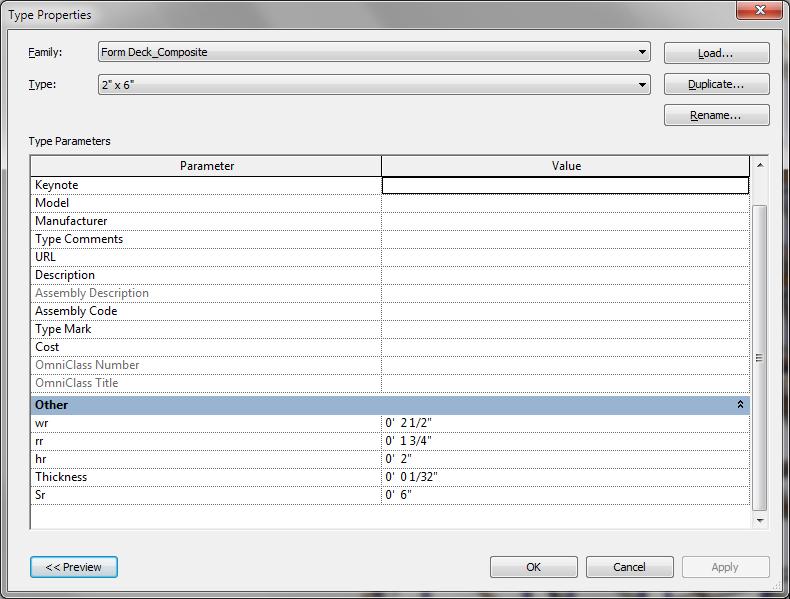
 2) Metal Deck (Thickness = 0 ) Layer 2 stands for a deck profile with the following properties: HR WR RR SR THICKNESS")
17 ETABS Deck Section In this example, there are two layers in the Revit Deck section: 1) Concrete Cast-in-Place (Thickness = 5 ) 2) Metal Deck (Thickness = 0 ) Layer 2 stands for a deck profile with the following properties: HR WR RR SR THICKNESS 17
18 Here is the procedure CSiXRevit uses to fill ETABS deck section properties: The layer with the maximum thickness is selected and treated it as the overall thickness of the section. This layer is used to define the material of the ETABS deck section. Slab Depth tc = overall thickness of section HR Deck Depth hr = HR Rib Width Top wrt = WR Rib Width Bottom wrb = RR Rib Spacing Sr = SR Composite Deck Studs diameter = RR Composite Deck Stud height (hs) = overall thickness of section - THICKNESS Layer Materials: ETABS imports the material of each layer. The material of the thickest layer is assigned to the Slab or Deck section. A default material is used if no material is defined in Revit. Users may later change the material of the different layers as required in ETABS. Floor Span Directions: The Revit span direction is imported for decks. A default direction is used if no span direction is defined in Revit. Floor Openings (Regular or Irregular): Openings defined in Revit by Modeling>Opening>Vertical Opening are imported into ETABS. All curves in such openings are converted into a number of smaller segments, which gives the suitable curvature for the area boundary. Ramps: All inclined slabs with four nodes are imported as ramp objects in ETABS. Openings The following openings are imported into ETABS from Revit: Horizontal Openings: These are imported as openings in the floors. Wall Openings: These are imported as openings in the walls (vertical planes). For details, please check Openings in Walls. Shaft Openings: These are imported as openings in the floors (horizontal planes). For details, please check Shaft Openings. 18
19 Shafts In Revit, a shaft opening element is defined as a 3D shaft having upper and lower limits (or offset elevations from upper and lower story levels). In ETABS the shaft is imported as horizontal floor openings at all the story levels that lie between the upper and lower limits of the 3D shaft. Footings The following footing properties are imported into ETABS from Revit: Points: All the points defining the shape of the footing are imported. In ETABS all columns that are located in this area are restrained. Width, Length and Thickness: For rectangular footings, the width, length and thickness are imported. In this case, ETABS locates all the columns within the rectangular footing area and restrains them. Note: Only rectangular footings are processed. Point Loads The following point load attributes are imported into ETABS from Revit: Load Case Name: It sets the corresponding load case name in ETABS. Location: It is used to define the point of application of the load. Fx, Fy, Fz, Mx, My, Mz: All forces and moments applied in the global direction, in Revit, are transferred in a similar manner into ETABS. Line Loads The following line load attributes are imported into ETABS from Revit: Load Case Name: It sets the corresponding load case name in ETABS. Start and End Point Locations: Used to define the start and end point of the line load. Line loads carrying the gravitational load and overlapping more than one beam are distributed to the corresponding beams in ETABS. In the case of a lateral line load, users must check no line load overlaps more than one beam; otherwise it is not processed in the ETABS analysis. Fx, Fy, Fz, Mx, My, Mz: All forces and moments applied in the global direction, in Revit, are transferred in a similar manner into ETABS. A Revit line load which includes more than one of these components is imported as several ETABS line loads because ETABS line loads are mono-directional. 19
20 Area Loads The following area load attributes are imported into ETABS from Revit: Load Case Name: It sets the corresponding load case name in ETABS. Points: Points are used to define the geometry of the loading area. Curved edges that are arc shaped are imported as arcs. Straight edges are imported as such. Other edges are tessellated, with the degree of approximation defined internally by Revit. LoadX, LoadY, and LoadZ: All loads applied in the global direction in Revit are transferred in a similar manner into ETABS. Non-uniform surface loads are not supported in ETABS and not imported. Load Cases The following load case attributes are imported into ETABS from Revit: Load Case Name: The same name is used for the ETABS load case. Load Case Category: It is used to define the load case type in ETABS. The mapping is shown in the following table: Revit Load Case Category Dead Live Wind Snow Roof Live Accidental Temperature Seismic ETABS Load Case Type Dead Live Wind Snow Live Other Other Quake Load Combos The following load combination attributes are imported into ETABS from Revit: Load Combination Name: The same name is used for the ETABS Load Combination Name. Load Cases: The same load cases list is used in ETABS to define the Load Combination. Load Case Factor: The same load case factors are used for the corresponding load cases in the ETABS load combination. ETABS Auto Select Lists ETABS automatically creates Auto-select lists based on Revit family types that are loaded in the current Revit project and being exported into ETABS. 20
21 Exporting from Revit to update an existing ETABS model The table below provides an overview of the data imported in ETABS when exporting from Revit to update an existing ETABS model: Action Model Element Supported Notes Creation of Grids Story Levels Materials Creates equivalent ETABS materials. Frames Transfers geometry, offsets, end releases, and beam and brace alignment points, into ETABS. Cuts all columns at story levels. Frame Sections Steel Sections Concrete Sections Walls Wall Properties Wall Openings Floors Slabs Properties Deck Properties Maps to ETABS database sections. Creates and maps equivalent ETABS sections. Update of Floor Openings Footings Joint Loads Frame Loads Shell Loads Load Cases Load Combos Grids Story Levels Materials Frames Frame Sections X X X Creates fixed joint restraints in ETABS wherever a footing occurs in Revit. 21
22 Deletion of Steel Sections Concrete Sections Walls Wall Properties Wall Openings Floors Slabs Properties Deck Properties Floor Openings Point Loads Line Loads Area Loads Load Cases Load Combos Grids Story Levels Frames Walls Wall Openings Floors Floor Openings Footings Point Loads Line Loads Area Loads Load Cases Load Combos X X X X X X X X X X X Walls with changing number of sides are replaced. Wall openings with changing number of sides are replaced. Floor openings with changing number of sides are replaced. IMPORTANT NOTE: Deletion of objects when updating a model only works if you are sending the ENTIRE model. If the selection only update feature is used, deletion of items is not supported. 22
23 Importing from ETABS to create a new Revit Project The table below provides an overview of the data imported in Revit when creating a new Revit project: Action Model Element Supported Notes Creation of Grids Story Levels Materials Frames Frame Sections Steel Sections Imports Concrete and Steel materials into Revit from ETABS. Limitation is the Revit project should have one default concrete and one default steel material for duplication, otherwise the material will be created in Revit but its parameters will not be updated, and the properties of the new materials are identical to those of the template materials. Imports steel columns based on splice locations in ETABS. Column alignment points are not exported to Revit because the concept is not supported in Revit. Concrete Sections Walls Wall Properties Wall Openings Floors Slabs Properties Deck Properties Footings Load Cases Joint Loads Frame object Loads Shell Member Loads Load Combos Creates and maps equivalent Revit sections. See mapping below. Slanted walls not imported. Creates equivalent Revit point line loads and trapezoidal line loads. Creates equivalent Revit area loads. 23
24 Mapping of ETABS section types to Revit families: Columns ETABS Rectangular Square Circular Beams and Braces ETABS Rectangular L T Steel Plate Steel Rod Revit Family Concrete-Rectangular-Column.rfa Concrete-Square-Column.rfa Concrete-Round-Column.rfa Revit Family Concrete-Rectangular Beam.rfa Precast-L Shaped Beam.rfa Precast-Single Tee.rfa Plate.rfa Round Bar.rfa 24
25 Importing from ETABS to Update an Existing Revit Project The table below provides an overview of the data imported in Revit when updating an existing Revit project: Action Model Element Supported Notes Creation of Grids Story Levels Materials Frames Frame Sections Steel Sections Concrete Sections Creates and maps equivalent Revit sections. See mapping at end of previous section. Walls Wall Properties Wall Openings Floors Slabs Properties Update of Deck Properties Floor Openings Footings Load Cases Joint Loads Line Loads Area Loads Load Combos Grids Story Levels Materials Frames Frame Sections Steel Sections Updates changes to column locations only for columns not meshed in ETABS and with a 1:1 correspondence between Revit and ETABS. You can choose between leaving columns meshed in ETABS in their original Revit locations or replacing them with the ETABS meshed columns. 25
26 Deletion of Concrete Sections Walls Wall Properties Wall Openings Floors Slabs Properties Deck Properties Floor Openings Load Cases Point Loads Line Loads Area Loads Load Combos Grids Story Levels Materials Frames Walls Wall Openings Floors Updates Beam, Column and Brace section assignments; however section parameters themselves do not update. If you would like to bring in the changes to the parameters from ETABS, create a new section with the desired parameters in ETABS and assign the new section to the frame. Updates changes in wall location only for walls not meshed in ETABS and with a 1:1 correspondence between Revit and ETABS. You can choose between leaving walls meshed in ETABS in their original Revit locations or replacing them with the ETABS meshed walls. Updates wall type assignments; however wall types themselves do not update. If a wall section is changed in ETABS, it is imported under a new name in Revit. Non-rectangular wall openings are not updated. Replaces floors which moved, were not meshed when brought in from ETABS, and with a 1:1 correspondence between Revit and ETABS. You can choose between leaving floors meshed in ETABS in their original Revit locations or replacing them with the ETABS meshed floors. Updates floor type assignments; however floor types themselves do not update. If a floor section is changed in ETABS, it is imported under a new name in Revit. Floor openings moved in ETABS are replaced. Area loads moved in ETABS are replaced. Non-rectangular wall openings are not deleted. 26
27 Floor Openings Load Cases Point Loads Line Loads Area Loads Load Combos Floor openings imported as a floor shaft and deleted in ETABS are not deleted. IMPORTANT NOTE: Deletion of objects when updating a model only works if you are sending the ENTIRE model. If the selection only update feature is used, items are not deleted. 27

28 Procedures Exporting from Revit to Create/Update a New/Existing ETABS Model IMPORTANT NOTE: CSiXRevit only exports the analytical models of Revit elements. All the analytical models of all Revit elements must be correctly connected to each other to ensure the stability of the ETABS model generated. Revit Model View 28

29 Revit Analytical Model View The following steps describe how to send a Revit analytical model to ETABS: 1. To create a new ETABS model, from the Revit menu select, Tools>External Tools>Export to Create New ETABS SAP2000 or SAFE Model. To update an existing ETABS model, from the Revit menu select, Tools>External Tools>Export to Update Existing ETABS or SAFE Model. 2. CSiXRevit counts the elements in the Revit project and displays the Export to Create New ETABS SAP2000 or SAFE Model form, or Export to Update Existing ETABS or SAFE Model form as may be the case: 29


30 Select the categories of Revit elements to export to ETABS. If you have selected some elements prior to starting the command and wish to only export those elements, check the corresponding box at the bottom of the form. Once you have made your selections, click OK. The Exporting to Create New ETABS SAP2000 or SAFE Model or Exporting to Update Existing ETABS or SAFE model information message box is shown and displays the progress of the export: 30
.")
31 3. Once the process has run its course, click OK. You are now asked to select a destination folder and filename. The file will be given the extension.exr. 4. Start ETABS if it is not already running. 5. To create a new ETABS model from your Revit project, you should not have any model open, not even an ETABS blank model (an ETABS blank model actually includes four story levels). By default ETABS creates a new model based on your.exr file. To update an existing ETABS model, open it. 6. From the menu, select File>Import>Revit Structure.exr file, and then select the.exr file to import. If you are creating a new model, this command is available from the ETABS Start Page. 31

32 7. The Revit Data Overview/Controls form is displayed: The top section of this form provides access to more forms which let you specify how Revit levels, materials and families are imported in ETABS. Any material property with a zero value, any unrecognized section, any section with a default material displays a warning. If a material property was not defined, or a material was not assigned in Revit, you can address the issue before the ETABS model is created. These issues can be addressed by clicking the corresponding Edit button. The bottom section of this form displays general controls that ETABS uses when importing the Revit project. The units selected here are used as the default units of the ETABS model. The length tolerance is the tolerance ETABS uses to align close X, Y, Z coordinates and to create connectivity when creating the finite element model for analysis. The Minimum Curve Length and Angle let you control how a curve is divided into straight line segments. When you check the Align close X, Y or Z Coordinates, ETABS may make small adjustments to the original coordinates in the.exr file. Adjustments are then made to the coordinates of grid lines, frame objects, and edges of shell objects that are parallel or almost parallel to the horizontal plane X or Y axis in the EXR file. These adjustments are two-fold: All imported such items are made actually parallel to the X or Y axis as applicable; and all such items that are almost aligned with each other are actually aligned. 32


33 To review the various story levels imported from Revit click the Edit button. The ETABS Story Data form is displayed, letting you change story heights and other story parameters, and add or delete story levels. 8. To review the Revit material properties imported, select the Edit button next to Total Materials. The Material Mapping form is displayed: 33

34 In this model four materials are imported. Any new ETABS material is created with the same name as the Revit material name. To map the Revit Material to a material other than the new ETABS material created, click on the ETABS material name. A combo box will be displayed with all of the existing ETABS materials currently in the ETABS model. To create a new material property to map your Revit material to, click Add. The ETABS Add Material form is then displayed. To see the properties of any imported material, select the material and click Edit. The ETABS Material Property Data form is then displayed: To check the original properties of the material in Revit, click Revit Data... The Revit Material Property Data form is displayed: 34


35 9. To see the Revit Frame Sections imported, select the Edit button next to Total Frame Sections. The Frame Section Mapping form is displayed: The first three columns display the original Revit family type, original family name, and the material assigned to any section imported from Revit. The fourth column is the ETABS section the Revit section is mapped to. The final column describes how the section is mapped or created. Only the ETABS Section Name column is editable. Clicking any row in the column displays a combo box that includes all section properties currently loaded in the current ETABS model. To add a section to the list, click the Add button the right side. 35
36 When ETABS imports the Revit data, it initially tries to match Revit section names to ETABS section names. It first searches through the loaded ETABS database sections. If not matched, it then searches all the ETABS section property files (.XML). It will map the section to the first section name that matches. To specify which files are searched, click the.xml Files button on the right side. The XML Property Files form is displayed: All the XML property files present in the ETABS installation directory are selected by default. A file can be added or removed from the ETABS search by checking or unchecking its checkbox in the list. To add a new file, click on the Add File button. To change the order in which ETABS searches the files, move their names up and down in the list using the arrow key buttons on the right side. If ETABS cannot create a section mapping by name, it tries to create the section parametrically. For most steel sections ETABS is able to find a match. For concrete sections, ETABS will create the sections parametrically. To see how Revit sections properties are mapped, see the section under Supported Workflows called Exporting from Revit to create a new ETABS model. Similar to the Material Mapping, details about the Frame Section Mapping can be edited by selecting the row, and clicking the Edit button. To save the mapping created, the mapping file can be exported by clicking the Export Mapping File button. Likewise, to import a previously created mapping file, click the Import Mapping File button. 10. To see the Revit floor sections imported, select the Edit button next to Total Floor Sections. The Floor Section Mapping form is displayed: 36


37 Again, you can specify the ETABS floor section the Revit floor type gets mapped to. By default an equivalent ETABS floor section is created and mapped. To create a new deck or slab section, use the buttons on the right side. After adding the deck or slab, the new ETABS floor section will show up in the drop down list. To review the details of an ETABS section, click on the row and then click the Edit button. The ETABS Slab Property Data or Deck Properties Data form, as applicable, is displayed: 37
38 11. To see the Revit wall sections imported, select the Edit button next to Total Wall Sections. The Wall Section Mapping form is displayed: Again, you can specify the ETABS wall section the Revit wall type gets mapped to. By default an equivalent ETABS wall section is created and mapped. To create a new wall section use the Add buttons on the right side. After adding the wall, the new ETABS wall section shows up in the drop down list. 12. Once you are satisfied with the mapping of materials and sections, in the Revit Data Overview/Controls form select OK. The ETABS model is created. 38

39 Exporting from ETABS to Create/Update a New/Existing Revit Project The following steps describe how to export your ETABS analytical model to create or update a Revit project: 1. Once you have edited, analyzed and designed your structure in ETABS, save the ETABS file by selecting the File>Save. 2. In ETABS, select File>Export>Revit Structure.exr File and specify a destination folder and filename in the Export ETABS-Revit Exchange File form which is displayed. 3. If you have selected objects in the model, and would like to export only those, select the appropriate box: 4. Start Revit if it is not already running. 5. To create a new Revit project from your ETABS model, open a Revit template that you would like to import your ETABS model into. It isn t required, but the import will come in faster and will be more predictable if you load all the beam, column, brace, deck, slab and wall families you would like ETABS sections to map to prior to importing. From the menu select, Tools>External Tools>Import to Create New Revit Project from ETABS, SAP2000 or SAFE. Select the.exr file you would like to import. CSiXRevit will try to load any required families that are not already loaded. To update an existing Revit project, first open it. Again, if you have new sections you defined in ETABS, the import will come in faster and will be more predictable if you load all the beam, column, brace, deck, slab and wall families you would like ETABS sections to map to prior to importing. From the Revit menu select, Tools>External Tools>Import to Update Existing Revit Project from ETABS. Select the.exr file to import. 39

40 6. Whether creating a new Revit project or updating an existing Revit project, after selecting the.exr file, the following form is displayed: On the left side, you can control the types of ETABS objects to import into the Revit project and the mapping of ETABS sections to Revit types. 40
41 Clicking the Frame Sections button under Mapping Options displays the Frame Section Mapping form: Changes to the mapping of ETABS sections to Revit sections can be made here. All Revit column beam and brace families and family types currently loaded in the project are displayed in the drop down lists. 41


42 Clicking the Floor Sections button displays the Floor Section Mapping form: Changes to the mapping of ETABS floor sections to Revit sections can be made here. All Revit floor families currently loaded are displayed in the drop down lists. Clicking the Wall Sections button displays the Wall Section Mapping form: Changes to the mapping of ETABS wall sections to Revit sections can be made here. All Revit wall families currently loaded are displayed in the drop down lists. 42
43 If you are updating a Revit project from an ETABS model, you have the choice to only update locations and releases, only update designs and load magnitudes, or update both: Also, when updating a Revit project from an ETABS model, there can be instances in which the 1:1 mapping of Revit elements to ETABS objects is lost because objects were meshed in ETABS. If this is the case, you have two options: 1. Delete the existing Revit elements, and let CSiXRevit create new elements corresponding to the objects that are meshed in ETABS. 2. Keep the existing elements as they are and use object mapping to control the assignment of section properties during the import. In the case of option #2, there can be situations in which the user has to make some decisions. For example, if a column in Revit runs from the ground floor to the top floor as a single element, when imported into ETABS, the column is cut at every floor level. When it is designed, different sections might be assigned to each segment of the column. When the column (that is now meshed in ETABS) is imported back into Revit, you have the option to 1) delete the original column in Revit and have CSiXRevit create a column with the varying sections or to 2) select one of the frame sections for the entire length of that column. To do this, select the corresponding checkbox and click the Objects button under Mapping Options. The Object Mapping form is displayed: 43

44 In this case, Column ID (139774) spans three floors in Revit but was meshed into three pieces in ETABS. When coming back into Revit, you can choose which section to assign to the entire length of the column. The same can be done with meshed beams, braces, floors and walls. Once you are satisfied with the object mappings, select OK and the ETABS model will be imported. 44
45 Reviewing the Log File (.log) Every time a model is sent from Revit to ETABS or from ETABS to Revit, a file with the extension.exrlog is created if it does not exist, or appended if it already exists. This file lists the project or model name, the workflow operation, and the time and date. It also lists any errors or omissions encountered in generating or importing the.exr file, and therefore, should be checked every time data is transferred. The.EXRlog file also lists the build numbers for CSiXRevit and Revit. The two should be identical to ensure no misinterpretation of data occurred. The first few lines of the.log file have the following format (the actual data may be different): CSixRevit Revit API Version = CSixRevit Build = _0700(x64) Current Revit Version = Current Revit Build = ( _0700(x64) The Build = numbers should be the same having the same Version numbers but different Build numbers does not guarantee data consistency. Finally, in the case of an incremental import, the changes made to the Revit project are listed. Added Area Load for the following elements: to replace to replace to replace to replace to replace to replace Added Floor for the following elements: to replace to replace to replace Changed Beam camber for the following elements: to C=1.75" to C=1.75" to C=1.75" to C=1.75" to C=1.75" to C=1.75" to C=1.75" 45
46 to C=1.75" to C=1.75" Changed Beam end reactions for the following elements: Changed Beam shear studs for the following elements: to (20) to (20) to (20) to (20) to (20) to (20) to (20) to (20) to (20) Moved Structural Member for the following elements: by ft, 0.00ft by ft, 0.00ft by ft, 0.00ft by ft, 0.00ft by ft, 0.00ft by ft, 0.00ft by ft, 0.00ft by ft, 0.00ft by ft, 0.00ft by ft, 0.00ft Each Revit element is identified by its Revit ID. You can view the element IDs by selecting Manage->Select by ID in the Revit ribbon, typing an ID, and clicking the Show button: Revit will find a view that contains the element, switch to that view, and highlight the element. 46
47 Known Limitations with CSiXRevit and ETABS 1. If your version of Windows includes strict UAC (User Account Control), you need to run ETABS.exe and Revit.exe with the option Run as Administrator. If Revit is not run with administrator privileges, there is a risk CSiXRevit will not be able to open the.exrlog file. In this case, CSiXRevit will not write any warnings to the log file but all warning messages will be displayed on the screen. 2. Revit floors that are grouped together may be treated as openings when importing into ETABS. 3. Import of European and Chinese steel sections from Revit to ETABS is possible if their corresponding.xml files are present in the ETABS folder. 4. Materials imported into Revit from ETABS may not always be properly assigned or the property values may not always be properly transferred. For this reason, material assignments and material property values should always be carefully checked in Revit after importing from ETABS. 47
48 Revit and SAP2000 Data Exchange Data exchange between CSiXRevit and SAP2000 supports two different workflows: 1) Exporting from Revit to create new SAP2000 model. 2) Exporting from Revit to update an existing SAP2000 model. SAP2000 v or later is required. 3) Importing from SAP2000 to create a new Revit project. 4) Importing from SAP2000 to update an existing Revit project. In this case, you may choose to update locations, designs, or both. SAP2000 v or later is required. Supported Workflows Exporting from Revit to create a new SAP2000 Model The table below provides an overview of the data transferred from Revit to SAP2000: Action Project Element Supported Notes Creation of Grid Lines Does not transfer. Materials Steel Concrete Does not transfer reinforcement properties. Aluminum Imports as isotropic Other SAP2000 material type. Generic Other Wood Frames Frame Sections Rolled Steel Sections Bar Joists Concrete Sections Walls Transfers geometry, beam and brace alignment points, and end releases into SAP2000. Ignores end offsets. Imports curved Revit framing as a series of short straight SAP2000 frame objects. Loads equivalent SAP2000 section profiles from the SAP2000.PRO files specified during import of the.exr file into SAP2000. Imports with None properties. Creates and maps equivalent SAP2000 sections. Imports walls as SAP000 area objects with wall openings imported as separate area objects with None properties. Imports 48
49 Wall Properties Floors Slabs Properties Slab on Deck Properties Footings Point Loads Line Loads Area Loads curved Revit walls as a series of short planar SAP2000 area objects. Warped walls with more than four sides not imported. Creates and maps equivalent SAP2000 thick shell sections. Imports floors as SAP000 area objects with floor openings imported as separate area objects with None properties. Creates and maps equivalent SAP2000 thick shell sections. Creates and maps equivalent SAP2000 thick shell sections with directional stiffness modifiers. Does not transfer. Creates SAP2000 joints if the load does not coincide with a previously created joint and does not line up with any frame objects. This will cause model instability that needs to be addressed. Creates SAP2000 frame objects with None properties if the load does not overlap any other frame object. If the load also does not line up with any imported floor or wall, it will cause model instability that needs to be addressed. Does not transfer. Load Cases Load Combinations Grid Lines Revit grid lines are not imported in the current version of SAP2000. Materials All Revit materials are imported into SAP2000 as isotropic materials. The following Revit material attributes are imported into SAP2000: Material Name: The same name is used in SAP
50 Material Class: Concrete and steel set to equivalent SAP2000 material types. Generic, aluminum, and wood material types set as Other SAP2000 material type. Young s Modulus: The first of Revit s three Young s modulus values (one for each direction) sets the SAP2000 material Young s modulus (E) value. If this value is zero, the default SAP2000 value is used. Poisson s Ratio: The first of Revit s three Poisson s Ratio values (one for each direction) sets the SAP2000 material Poisson s Ratio (U) value. If this value is zero, the default SAP2000 value is used. Shear Modulus: The first of Revit s three Shear Modulus values (one for each direction) is compared to the value of the material Shear Modulus (G) computed by SAP2000. If the two differ by more than one percent in SAP2000, a warning is reported in the log file. Thermal Expansion Coefficient: The first of Revit s three thermal expansion coefficients (one for each direction) sets the SAP2000 material thermal expansion coefficient (Alpha). If this coefficient is zero, the default SAP2000 value is used. Unit weight: The Revit unit weight sets both the SAP2000 material weight density (w) and mass density (m). In SAP2000 the mass density is calculated by dividing the weight density by the gravitational constant (g). If the unit weight is zero, the default SAP2000 value is used. Behavior: Revit uses this tag to distinguish between isotropic and orthotropic materials. All Revit materials are imported as isotropic materials in SAP2000. Any orthotropic material generates a warning in the log file. Concrete Compression: In the case of a concrete material, the Revit concrete compression sets the SAP2000 concrete compressive strength f c. Lightweight: The value of this tag is used to identify a concrete material as lightweight concrete in SAP2000. Yield Stress: In the case of a steel material, this value sets the SAP2000 minimum yield stress Fy. If the yield stress is zero, the default SAP2000 value is used. Tensile Strength: In the case of a steel material, this value sets the SAP2000 minimum tensile stress Fu. If the tensile stress is zero, the default SAP2000 value is used. The following Revit material attributes are not imported in the current version of SAP2000: Damping Ratio Bending Reinforcement Shear Reinforcement Resistance Calculation Strength Shear Strength Reduction Steel Reduction Factor Only those materials associated with walls, framing, or floors in the Revit project are imported into SAP
51 Frames The following Revit frame member attributes are imported into SAP2000: Analytical Model End Points: The point coordinates are used to locate matching joints already created, and when none can be found, create new joints. When importing end points, SAP2000 views two points as coincident if none of their coordinates differ by more than 1/100 th of a foot. This level of precision corresponds to the level of precision in the Revit database. Frame Curves: SAP2000 does not support curved frame objects and any curved Revit member is imported as a series of short straight SAP2000 frame objects. Revit controls how the curve is broken into segments. Family Type: See Frame Sections below. Frame Releases: All frame releases defined in Revit are imported into SAP2000 as line object releases. Releases that cause model instability are restrained and a warning is reported in the log file. Beam Insertion Point: In Revit, a beam insertion point is defined by the following two parameters: o Z-Direction Justification o Lateral Justification SAP2000 calculates the corresponding alignment point on the basis of these two parameters. If these parameters are not defined, then the default alignment point (middle center) is chosen. Column Orientation and Beam and Brace Cross-Section Rotation: This angle measures the rotation of the member around its longitudinal axis in Revit and sets the value of the Rotation about 1 angle in elements imported into SAP2000. The two angles are measured identically in both programs except they differ by 90⁰ in the case of columns. The following Revit frame member attributes are not imported into the current version of SAP2000: Column Beam and Brace Vertical End Offsets: Revit column beams and brace vertical end offsets are not imported into SAP2000 because Revit element end points are retrieved from their analytical models. Column Insertion Point: The alignment point of imported columns is always middle center. Rigid Links Frame Sections Frame member sections are defined in Revit by their assigned family type. 51
52 When reading an.exr file, SAP2000 attempts to match each Revit frame member family type to an identically named section profile defined in the AISC13.pro file (or AISC13M.pro depending on the display unit system in use when importing begins). In the absence of such a match, SAP2000 checks if the type is from one of the parametric families (Table 2) for which it knows how to generate sections for. Any frame member type not matched becomes an unrecognized type for which SAP2000 requires additional user input. This additional input is entered in the Import Revit.exr file form displayed when an import into SAP2000 begins. Here all unrecognized types are listed in a table, allowing them to be manually matched to predefined SAP2000 section profile names or, as a last resort, to the SAP2000 None property. Here additional section properties databases (.PRO files) can be loaded. When adding a properties file (.PRO), the unrecognized Revit types are checked against the section profile names in this file. This may resolve most of the unrecognized types if the correct properties file (.PRO) is chosen. SAP2000 saves the properties files (.PRO) manually loaded and the manual assignments made here in a file with an.exrmap extension. When importing into SAP2000 the same Revit project again, SAP2000 will automatically restore these choices. When loading an.exr file, SAP2000 keeps track of which materials are used in conjunction with which section profiles. When a section profile is always used with the same material, the corresponding section property is named after the profile. If a section profile is used 52
53 with a number of different materials, the various corresponding section properties will have compound names consisting of the profile name with the relevant material name appended. The parameters for concrete and wood structural families are listed in the table below: Member Type Family Name Parameters CONCRETE CONCRETE-RECTANGULAR- B, H COLUMNS COLUMN CONCRETE-ROUND-COLUMN B CONCRETE-SQUARE- B COLUMN PRECAST-RECTANGULAR COLUMN B, H CHAMFER PRECAST-DOUBLE TEE WIDTH, TEE WIDTH, CONCRETE STEM WIDTH, SLAB FRAMING DEPTH, DEPTH PRECAST-INVERTED TEE H1, H, B, SEAT PRECAST-L SHAPED BEAM H1, H, B, SEAT PRECAST-RECTANGULAR B, H BEAM PRECAST-SINGLE TEE WIDTH, STEM WIDTH, SLAB DEPTH, DEPTH WOOD DIMENSION LUMBER- B, D, SY, SX, IY, IX, A COLUMNS COLUMN GLULAM-SOUTHERN PINE- B, D, SY, SX, IY, IX, A COLUMN GLULAM-WESTERN SPECIES- B, D, SY, SX, IY, IX, A COLUMN PSL-PARALLEL STRAND B, D, SY, SX, IY, IX, A LUMBER-COLUMN TIMBER-COLUMN B, D, SY, SX, IY, IX, A WOOD DIMENSION LUMBER B, D, SY, SX, IY, IX, A FRAMING GLULAM-SOUTHERN PINE B, D, SY, SX, IY, IX, A GLULAM-WESTERN SPECIES B, D, SY, SX, IY, IX, A LVL-LAMINATED VENEER B, D, SY, SX, IY, IX, A LUMBER TIMBER B, D, SY, SX, IY, IX, A OPEN WEB JOIST B, H PLYWOOD WEB JOIST B, H Table 2: Parameters used in SAP
54 In-place Family Members Walls Floors Revit in-place family members are not imported into the current version of SAP2000. Revit walls are imported into SAP2000 as area objects. The following Revit wall attributes are imported into SAP2000: Analytical Model End Points: The point coordinates are used to locate matching joints already created, and when none are found, create new joints. Wall Curves: Curved vertical Revit walls are imported as a series of short planar SAP2000 area objects. Revit controls how the curve is broken into segments. Wall Openings (Regular rectangular shape): This refers to wall openings drawn with the Revit selection Modeling>Opening>Wall Opening. These openings are imported into SAP2000 as area objects, with None properties, that overlap the area object generated for the wall. Wall Thickness and Material: Revit walls may consist of different layers with different thickness and materials. The thickness and material type of the layer with the maximum thickness are used to find or create an appropriate SAP2000 thick shell property. Wall section properties are named after the Revit wall types. The suffix -WALL is appended to this name if the name is also used for a floor type. Warped walls with more than four sides not imported. Revit floors are imported into SAP2000 as area objects. The following Revit floor attributes are imported into SAP2000: Analytical Model End Points: The point coordinates are used to locate matching joints already created, and when none can be found, create new joints. Floor Curves: SAP2000 does not support curved edges in area objects. All curves in Revit floors are approximated as a series of straight segments. Revit controls how the curve is segmented. Floor Thickness and Material: Revit floors may consist of different layers. If there is only one layer, its thickness and material are used to define an equivalent SAP2000 thick shell property. If there is more than one layer, and one of the layers corresponds to a Revit deck profile and at least one other is a concrete layer, SAP2000 creates a concrete thick shell property. Its thickness is equal to the total thickness of all the concrete layers and the membrane and bending stiffness modifiers assigned will account for the presence of deck ribs. Floor section properties are named after the Revit floor types. Floor Span Direction: Sets the SAP2000 area object local axes. Inclined Slabs: Also imported into SAP2000 as area objects. 54
55 Openings Revit openings are imported into SAP2000 as area objects with None properties. This includes: Floor Openings Wall Openings Shaft Openings: These are imported as SAP2000 area objects located at the base of the shaft with None properties. Footings Revit footings are not imported in the current version of SAP2000. Point Loads The following Revit point load attributes are imported into SAP2000: Load Case Name: Sets the load pattern name in SAP2000. Location: The point coordinates are used to locate a matching joint already created. SAP2000 views a joints and a point load as coincident if none of their coordinates differ by more than 1/20 th of a foot. This level of precision corresponds to the level of precision in the Revit database. When no coincident joint is found, SAP2000 looks for an underlying frame object. If no suitable frame object is found, SAP2000 creates a new joint. This new joint creates model instability that needs to be addressed. Fx, Fy, Fz, Mx, My, Mz: All forces and moments are defined in the global coordinates system in Revit and defined in SAP2000 in a similar manner. Line Loads The following Revit line load attributes are imported into SAP2000: Load Case Name: Sets the corresponding load case name in SAP2000. Start and End Point Locations: These define the start and end points of the line load. A line load overlapping more than one frame object is distributed on the corresponding frame objects. If all or part of the load cannot be assigned to frame objects, new frame objects with None properties are created. This will cause model instability if the load does not also line up with any imported floor or wall. Fx, Fy, Fz, Mx, My, Mz: All forces and moments are defined in the global coordinates system in Revit and defined in SAP2000 in a similar manner. Area Loads Revit area loads are not imported in the current version of SAP
56 Load Cases Revit load cases are imported into SAP2000 as both load patterns and load cases. One load pattern and one load case are both created in SAP2000 for each Revit load case. The following Revit load case attributes are imported into SAP2000: Load Case Name: Sets the corresponding load case name in SAP2000. Load Case Category: This defines the load case type in SAP2000. The mapping is shown in the following table: Revit Load Case Category Dead Live Wind Snow Roof Live Accidental Temperature Seismic SAP2000 Load Case Type Dead Live Wind Snow Live Other Temperature Quake Load Combinations The following Revit load combination attributes are imported into SAP2000: Load Combination Name: The same name is used in SAP200. Load Cases: The same load case list is used in SAP2000. Load Case Factors: The same load case factors are used in SAP
57 Importing from SAP2000 to create a new Revit Project The table below provides an overview of the data transferred from SAP2000 to Revit: Action Model Element Supported Notes Creation of Grid Lines Does not transfer. Joints Does not transfer, but force joint loads transfer. Materials (isotropic) Creates material. Limitation is the Revit project should have one default concrete and one default steel material for duplication, otherwise the material will be created in Revit but its parameters will not be updated, and the property of the new materials are identical to those of the template materials. Materials Does not transfer. (orthotropic) Frames Vertical Frames Creates as columns in Revit. Alignment point, end length offsets and joint offsets do not transfer. Horizontal Frames Creates as beams in Revit. End length offsets and joint offsets do not transfer. Other Frames Creates as braces in Revit. Alignment point, end length offsets and joint offsets do not transfer. Cables Imports as columns, beams, or braces based on their alignment. Frame Sections None Does not transfer frame object. Tapered Sections Does not transfer frame object. Steel Sections Maps to Revit family types with matching names. If not loaded, family type is located and if found, loaded. Joists Maps to Revit family types with matching names. If not loaded, family type is located and if found, loaded. Concrete Sections Creates and maps equivalent Revit sections. SAP2000 Auto Does not transfer. Select Lists Shells Vertical Shells Imports as walls in Revit. 57
58 Horizontal Shells Shells in other planes Non-planar shells Shell Properties None Membrane Plate Shell Layered Planes Vertical Planes Horizontal Planes Other Planes ASolids Solids Link/Support Tendons Joint Loads Force Displacement Frame Loads Concentrated Distributed Temperature Strain Target Force Internal Force Shell and Plane Loads Uniform Uniform to Frame Surface Pressure Pore Pressure Temperature Strain Load Patterns Imports as floors in Revit. Imports in Revit as floors with a slope. Slope value may require user adjustment. Does not transfer. Does not transfer the shell. Does not transfer stiffness modifiers. Does not transfer. Imports as walls in Revit. Imports as floors in Revit. Imports in Revit as floors with a slope. Slope value may require user adjustment. Does not transfer. Does not transfer. Does not transfer. Does not transfer. Loads defined in coordinate systems other than local or global do not transfer. Does not transfer. Loads defined in coordinate systems other than local or global do not transfer. Does not transfer. Does not transfer. Loads defined in coordinate systems, other than local or global do not transfer. Does not transfer. Imports as Revit load cases, unless their type does not correspond to a predefined Revit load case category. 58
59 Load Cases Static Linear Other than Static Linear Load Combinations Imports into Revit only if all static linear load cases each refer to a single load pattern. Load patterns not imported into Revit are not included in the list of Revit load cases. Does not transfer. Imports as Revit load combination only if it refers to more than one load pattern. Load patterns not imported into Revit are not included in the list of Revit load cases. Grid Lines SAP2000 grid lines are not imported into Revit. Joints While model geometry is imported into Revit, SAP2000 joints themselves are not imported. This restriction includes supports. Materials CSiXRevit creates Revit materials with the same names as the SAP2000 materials if they are not already in the project template: Material Name: The same name is used in Revit. Material Type: Concrete and steel set to equivalent Revit material classes. Aluminum, Cold-formed steel and Other set to Revit Generic material class. Concrete Compressive Strength: In the case of a concrete material, CSiXRevit attempts to create a new concrete material which duplicates a Revit concrete material with the same concrete compressive strength if it can find one in the project template. If not, a new concrete material is created but its concrete compressive strength differs from the original SAP2000 value. Lightweight Concrete: In the case of a concrete material, sets the corresponding Revit attribute. Minimum Yield Stress: In the case of a steel material, CSiXRevit attempts to create a new steel material which duplicates a Revit steel material with the same minimum yield stress if it can find one in the project template. If not, a new steel material is created but its minimal yield stress differs from the original SAP2000 value. Only materials associated with exported SAP2000 frame, cable, and area objects are imported into the new Revit project. 59
60 Frame objects SAP2000 frame objects are imported into Revit as columns, beams, or braces depending on whether they are vertical, horizontal, or inclined. Frame object with None properties, nonprismatic properties, or a material that cannot itself be exported are not imported into Revit. The following SAP2000 frame member attributes are imported into Revit: Name: The SAP2000 name is imported into Revit as a shared parameter. Start and End Joints: The coordinates of their start and end joints set the end points of the Analytical Models of the new Revit columns, beams, or braces. Properties: The name of the SAP2000 properties is exported. When importing frame objects from an.exr file into Revit, CSiXRevit always attempts to locate and load a Revit family type with the same name as the SAP2000 properties name. Note that the search is much quicker if the relevant Revit sections are already loaded in your Revit prototype or project before you import your SAP2000 model. For some concrete frame object properties corresponding to the families listed in Table 2, CSiXRevit creates a new family type, if it is not already in the new Revit project, and another type of the same family, if it is already loaded. Therefore if a SAP model includes concrete frame objects, at least one type of the relevant concrete member families in Revit prototype or project should be loaded prior to import. Frame Releases: See Limitations. Insertion Point: Only the insertion points of SAP2000 horizontal area objects are imported into Revit, as neither Revit columns nor braces have Z-Direction or Lateral Justification attributes. Local Axes: Sets Revit Column Orientation and Beam and Brace Cross-Section Rotation. The following SAP2000 frame object attributes are not imported into Revit: Frame Joint Offsets End Length Offsets Cable Objects SAP2000 cable area objects are imported into Revit as columns, beams, or braces depending on whether they are vertical, horizontal, or inclined. Cable area object with None properties or a material that cannot itself be exported are not imported into Revit. The following SAP2000 cable area object attributes are imported into Revit: Name: The SAP2000 name is imported into Revit as a shared parameter. Start and End Joints: The coordinates of their start and end joints set the end points of the Analytical Models of the new Revit columns, beams, and braces. Properties: The name of SAP2000 properties is exported. When importing cable area objects from an.exr files into Revit, CSiXRevit always attempts to locate and load a Revit family type with the same name. 60
61 Area Objects SAP2000 area objects are imported into Revit in different ways based on their orientation. Vertical area objects are imported into Revit as walls. Horizontal area objects are imported into Revit as floors. Other planar area objects are imported into Revit as floors with a slope. Non-planar area objects, area objects with None properties, or with layered properties, are not imported into Revit. The following SAP2000 shell and plane attributes are imported into Revit: Name: The SAP2000 name is imported into Revit as a shared parameter. Joints: Their coordinates set the corners of the new Revit wall or floor analytical model. In the case of area objects that are neither vertical nor horizontal, floors with a slope are created in Revit. Note that while their slope is initially set correctly, Revit subsequently resets it to a different value. The correct slope is available as a shared parameter named Computed slope and you need to reset the slope of the floor to this parameter value. Properties: SAP2000 shell, membrane, plate, and plane properties are imported into Revit as wall or floor type and as a single layer. The thickness and material matches the SAP2000 thickness and material. Note that stiffness modifiers are not exported. Solid Objects, ASolid Objects, Link/SupportObjects, Tendon Objects SAP2000 Solid objects, ASolid objects, Link/Support objects, and Tendon objects are not imported into Revit. Force Joint Loads and Frame object Concentrated Loads SAP2000 force joint loads and frame object concentrated loads are imported into Revit as point loads. Not all force joint loads are imported: see Load Pattern and Coordinate System below. The following SAP2000 force joint load attributes are imported into Revit: Load Pattern: It sets the Revit load case name. Loads part of a load pattern that is not itself exported are not imported into Revit. Coordinate System: Joint loads and frame object concentrated loads defined in coordinate systems other than the local joint coordinate system or the model global coordinate system are not imported into Revit. Force X, Force Y, Force Z, Moment about X, Moment about Y, and Moment about Z: Set the values of Fx, Fy, Fz, Mx, My, Mz in Revit. Ground displacement joint loads are not imported into Revit. Frame object Loads Frame object distributed loads are imported into Revit as line loads. Distributed loads consisting of a sequence of trapezoidal loads are imported as multiple loads with one Revit 61
62 line load for each trapezoidal segment. Not all force joint loads are imported: see Load Pattern and Coordinate System below. The following SAP2000 frame object load attributes are imported into Revit: Load Pattern: It sets the Revit load case name. Loads part of a load pattern that is not itself exported are not imported into Revit. Coordinate System: Frame object distributed loads defined in coordinate systems other than the local joint coordinate system or the model global coordinate system are not imported into Revit. Load Type, Direction and Load: Set the values of Fx1, Fx2, Fy1, Fy2, Fz1, Fz2, Mx1, Mx2, My1, My1, My2, Mz1, and Mz2 in Revit. Projected load magnitudes are converted to absolute load magnitudes based on the geometry of the frame object. Temperature, strain, target force and internal force frame object loads are not imported into Revit. Area Object Loads Area object uniform, uniform to frame, and surface pressure loads are imported into Revit as area loads. Not all force joint loads are imported: see Load Pattern and Coordinate System below. The following SAP2000 area object loads attributes are imported into Revit: Load Pattern: It sets the Revit load case name. Loads part of a load pattern that is not itself exported are not imported into Revit. Coordinate System: Area Object distributed loads defined in coordinate systems other than the local joint coordinate system or the model global coordinate system are not imported into Revit. Load Direction and Load: Set the value of Fx1, Fy1, Fz1, in Revit. Projected load magnitudes are converted to absolute load magnitudes based on the geometry of the area object. Area object temperature loads, strain loads, and pore pressure loads are not imported into Revit. 62
63 Load Patterns SAP2000 load patterns with types corresponding to a predefined Revit load case category are imported into Revit as load cases. The following SAP2000 load pattern attributes are imported into Revit: Load Pattern Name: The same name is used in Revit. Load Case Type: It sets the Revit load case nature and category. The mapping is shown in the following table: SAP2000 Load Case Type Dead, Super Dead Live, Reducible Live, Pattern Live Roof Live, Ice Snow Wind Quake Temperature, temperature gradient Other Not listed above Revit Load Case Category Dead Live Roof Live Snow Wind Seismic Temperature Not exported Not exported Load patterns with types that do not correspond to any predefined Revit load case category are not imported into Revit, and neither are any of their constituent loads. Load Cases If any SAP2000 static linear load case refers to more than one load pattern, than the static linear load cases are imported into Revit as load combinations, in place of the SAP2000 load combinations. The following SAP2000 load case attributes are imported into Revit: Load Case Name: The same name is used in Revit. Load Patterns: Set the list of Revit load cases. Load patterns not imported are not included in the Revit list. Load Pattern Factors: Identical load case factors are used in Revit, unless the load pattern list includes load patterns that were not exported. Their factors are not imported into Revit. SAP2000 load cases that are not static or are not linear are not imported into Revit. Load Combinations 63
64 If all the SAP2000 static linear load cases each refer to a single load pattern, then the SAP2000 load combinations are exported as Revit load combinations. When load combinations are exported, their following attributes are exported: Load Combination Name: The same name is used in Revit. Load Cases: Sets the list of Revit load cases. The Revit list is made of the load pattern names that each load case in the SAP2000 list refers to. Load patterns not imported are not included in the Revit list. Load Case Factors: If all the load cases in the list of load cases refer to their load patterns with a scale factor of 1, the same load case factors are used in Revit. If any load case refers to a load pattern with a scale factor other than 1, the Revit load case factors are adjusted accordingly. Scale factors for load patterns not imported are not included. 64

65 Procedures Exporting from Revit to create a new SAP2000 Model IMPORTANT NOTE: CSiXRevit only exports the analytical models of Revit elements. All the analytical models of all Revit elements must be correctly connected to others to ensure the stability of the SAP2000 model generated. The following steps describe how to export a Revit analytical model into SAP2000: 1. With Revit running, open a project you want to export. 2. From the Revit menu, select Tools>External Tools>Export to Create New ETABS or SAP2000 Model. 3. CSiXRevit counts the objects in the Revit project and displays the Export to Create New ETABS or SAP2000 Model form: Select the types of elements to send to SAP2000. If you have selected some objects prior to starting the command and wish to only export those objects, check the corresponding box at the bottom of the form. Once you have made your selections, click OK. 65
66 The Exporting to Create New ETABS or SAP 2000 Model message box is shown and displays the progress of the export: 4. Once the process has run its course, click OK. You are now asked to select a destination folder and filename. The file will be given the extension.exr. 5. Start SAP2000 if it is not already running. If it is already running and you want to retain the changes you made to the current model, save the current model. SAP2000 always creates a new model when importing an.exr file. 6. Select a SAP2000 unit system. If any issues arise during the import part of the exchange, SAP2000 generates a log file in which the locations of the problematic objects are reported in meters if you select metric units, or in feet otherwise. 7. From the menu, select File>Import>Revit Structure.exr File. The Import Revit Structure.exr file form is displayed. Click the Select EXR File button, and select the.exr file to import. 66

67 A summary of its contents is displayed: If any of the framing member family type names in the Revit project do not match the SAP2000 section profile names listed in AISC13.pro, the form includes a table listing all unrecognized types: The default SAP2000 profile selected in the right column for each unrecognized type in the left column is the closest alphabetical match in AISC13.pro (or AISC13M.pro depending on the unit system in use when the import began). 67
68 68

69 8. Click the Add Sections File button to load additional SAP2000 section properties databases (.PRO file). Alternately, you can directly edit the default filename in the field next to the button, pressing the TAB key when you are done. The Revit types that now have a name match like C250X30 in the example above are removed from the list: 9. For each unknown Revit type in the left column, if the corresponding SAP2000 section profile in the right column is not correct, choose another one from the drop-down list of predefined profiles: 69
70 None SAP properties are always available at the top of the list. SAP2000 saves your choices in a file which has an.exrmap extension. Importing the same Revit project again restores your choices. 10. Select what to import by checking or unchecking the relevant check boxes. (When checking Area Loads, you will receive a reminder that Area Loads cannot be imported into the current version of SAP2000.) 11. Click the Import in SAP2000 button. After a few moments, SAP2000 displays the newly imported model. 12. If any issues arise during the import part of the exchange, you will be prompted to review the log file. 70

71 Importing from SAP2000 to create a new Revit Project The following steps describe how to export a SAP2000 model to create a new Revit project: 1. With SAP2000 running, open a model you want to export. 2. Select File>Export>Revit Structure.exr File. The Export Revit Structure.exr File form is displayed. It includes a summary of the model contents on the left side and a table with level names on the right side: Unlike Revit, SAP2000 does not include the concept of story levels because it is a general purpose analysis program. Therefore, Revit levels need to be created when a SAP2000 model is imported into Revit. The form gives you control over which levels are created, their names, their elevations, and how exported SAP2000 objects are assigned to them in Revit. 71
72 3. If the joints in the SAP2000 model occur at a large number of different z elevations, you will probably want to create Revit levels only for a small subset of these elevations. In that case, uncheck the check box at the top of the levels table. It unchecks all the levels at once: 4. Check the box next to each story level you want created. As you check levels, SAP2000 computes default cutoff elevations and displays them in the At or Below field. SAP2000 area objects are imported into Revit as walls, floors, or ramps and SAP2000 frame and cable objects are imported into Revit as columns, beams or braces. The top and bottom levels of these Revit walls, columns and braces, and the reference levels of these beams and slabs are assigned based on the relationship between the level cutoff elevations and the z-coordinates of the joints defining the original SAP2000 objects. You can override any cutoff elevation by typing over a new elevation and pressing the TAB key as long as you do not set it lower than the corresponding level elevation, or higher than the elevation of the next level to be created above. 72
73 Likewise, you can rename any level by typing a new name, and change its elevation by typing a new elevation: SAP2000 saves your level data in a file which has an.exrmap extension. Exporting the same SAP20000 model again restores your level data. 5. Select what to export by checking or unchecking the relevant check boxes. 6. The Metric check box controls the units in which level elevations are displayed, the family names of the concrete section types created in Revit, and the units of the log file. 7. By default, the.exr file written is written in the same folder as the model and its name is the name of the model with an.exr extension. To save the.exr file in a different folder or under a different name, click the Save As... button. Alternately, you can directly edit the default filename in the field next to the button, pressing the TAB key when you are done. 8. Click the Create EXR File button. 9. If any issues arise during the export part of the exchange, you will be prompted to review the log file. Please take a moment to do so. 73
74 You are now ready to import the.exr file in Revit. You import an.exr file written by SAP2000 exactly like an.exr file written by ETABS: 10. Start Revit if it is not already running. 11. Create a new Revit project. Note while it isn t required, the import will come in much faster if your Revit template already contains all the column, beam, brace, slab and wall family types you would like SAP2000 sections to map to. 12. From the menu, select Add-Ins>External Tools>Import to Create New Revit Project from ETABS or SAP2000. Select the.exr file to import. CSiXRevit attempts to locate and load family types that are not already loaded. 13. The Import to Create New Revit Project from ETABS/SAP2000 form is displayed: On the left side, you can control the types of SAP2000 objects to import into the new Revit project. 74

75 Under Mapping Options, click the Frame Sections button, to see the Frame Section Mapping form: Changes to the mapping of SAP2000 sections to Revit sections can be made here. All Revit column, beam, and brace families currently loaded are displayed in the drop-down lists. 75

76 Clicking the Floor Sections button displays the Floor Section Mapping form: Changes to the mapping of SAP2000 floor sections to Revit sections can be made here. All Revit floor families currently loaded are displayed in the drop-down lists. Clicking the Wall Sections button displays the Wall Section Mapping form: 76
77 Changes to the mapping of SAP2000 wall sections to Revit sections can be made here. All Revit wall families currently loaded are displayed in the drop-down lists. 14. Once you have set up all of your mapping, select the OK button. After a few moments, your Revit project is displayed. 15. If any issues arise during the import part of the exchange, you will be prompted to review the log file. Please take a moment to do so. 77
78 Known Limitations with CSiXRevit and SAP Windows with UAC: With strict UAC (User Account Control), users must Run as Administrator (for SAP2000.exe and Revit.exe). If Revit is not run as administrator, there is a risk CSiXRevit will not be able to open the.exrlog file. In this case, CSiXRevit will not write any warnings to the log file but all warning messages will be displayed on the screen. Directly sending data to SAP2000 may not work if Revit is not run as administrator. 2. In the case of area objects that are neither vertical nor horizontal, floors with a slope are created in Revit. While their slope is initially set correctly, Revit subsequently resets it to a different value. The correct slope is available as a shared parameter named Computed slope and you need to reset the slope of the floor to this parameter value. 3. Materials imported into Revit from SAP2000 may not always be properly mapped or the property values may not always be properly transferred. For this reason, material mapping and material property values should always be carefully checked in Revit after importing from SAP See other limitations described in the previous sections for SAP
79 Revit and SAFE Data Exchange Data exchange between CSiXRevit and SAFE supports four different workflows: 5) Exporting from Revit to create a new SAFE model. 6) Exporting from Revit to update an existing SAFE model. 7) Importing from SAFE to create a new Revit project. 8) Importing from SAFE to update an existing Revit project. Supported Workflows Exporting from Revit to create a new SAFE model The table below provides an overview of the data imported in SAFE when exporting from Revit to create a new SAFE model: Action Project Element Supported Notes Creation of Grid Lines Story Levels Materials Structural Columns and Structural Framing Let you select which horizontal slice of the project to import. Imports only concrete columns, braces and beams, and only columns with rectangular or circular section, and only beams with rectangular section. Steel Column and Framing Family Types Concrete Column and Framing Family Types Walls Imports only circular or rectangular column sections, and only rectangular beam sections. Slanted walls and walls with material other than concrete not imported. 79
80 Wall Family Types Wall Openings Floors Floor Family Types Floor Openings Footings Point Loads Line Loads Area Loads Load Cases Load Combos Creates and maps equivalent SAFE wall sections. Floors with a filled steel deck or made of a material other than concrete not imported. Sloped floors with more than four outer corners are projected on a horizontal plane. Creates and maps equivalent SAFE slab and deck sections. Non-uniform area loads not imported. Creates both a SAFE load pattern and load case for each Revit load case. Grids The following Grid attributes are created in SAFE: Grid Name: The same grid name is used in the SAFE grid bubble. Grid Points: The start and end points are used to define the general grid line in SAFE. Curved Grid: The center point, radius, start angle and aperture are used to define the circular grid line in SAFE. Materials The following material attributes are created in SAFE: Material Name: The same name is used in SAFE. Material Type: The Revit material type is used to identify the SAFE material type, namely Concrete, Steel or Other. Young s Modulus: The Young s modulus values from Revit set the SAFE material Young s modulus (E). These three values (for the three different directions) cannot be zero in 80
81 SAFE. If the first value is zero, then the default SAFE value is used. If any of the remaining two are zero, then the first non-zero value is used. For an isotropic material, the first value is used for all other directions. Poisson s Ratio: Poisson s Ratio values from Revit set the SAFE material Poisson s Ratio (u). These three values (for the three different directions) cannot be zero in SAFE. If the first value is zero, then the default SAFE value is used. If any of the remaining two are zero, then the first non-zero value is used. For an isotropic material, the first value is used for all other directions. Shear Modulus: Shear Modulus value from Revit set the SAFE material Shear Modulus (G). If the Revit material is defined as isotropic, then SAFE calculates this value on the basis of the Young s Modulus and the Poisson s Ratio. In the case of an orthotropic material, these three values (for the three different directions) cannot be zero in SAFE. If the first value is zero, then the default SAFE value is used. If any of the remaining two are zero, then the first non-zero value is used. Thermal Expansion Coefficient: The thermal expansion coefficient from Revit sets the SAFE material thermal expansion coefficient (Alpha). These three values (for the three different directions) cannot be zero in SAFE. If the first value is zero, then the default SAFE value is used. If any of the remaining two values are zero, then the first non-zero value is used. For an isotropic material, the first value is used for all other directions. Weight Density and Mass Density: The unit weight value from Revit sets the SAFE material weight density (w) and mass density (m). In SAFE, the mass density is calculated by dividing the weight density by the gravitational constant (g). The weight density cannot be zero in SAFE. If the unit weight is zero in Revit, then the default SAFE densities are used. Damping Ratio: This value is not in used in the current version of SAFE. Bending Reinforcement: The bending reinforcement value from Revit sets the SAFE material main reinforcement Fy if the type is concrete. If this value is zero in Revit, then the default SAFE value is used. Shear Reinforcement: The shear reinforcement value from Revit sets the SAFE material shear reinforcement Fy if the type is concrete. If this value is zero in Revit, then the default SAFE value is used. Resistance Calculation Strength: The resistance calculation strength from Revit sets the SAFE material f c factor. If this value is zero in Revit, then the default SAFE value is used. Behavior: The Revit behavior tag is used to identify the isotropic or orthotropic materials in SAFE. Concrete Compression: The concrete compression value from Revit sets the SAFE material f c if the type is concrete. Lightweight: The Revit lightweight tag is used to identify the lightweight concrete material in SAFE. Shear Strength Reduction: This value is not in used in the current version of SAFE. Yield Stress: This value is not in used in the current version of SAFE. 81
82 Tensile Strength: This value is not in used in the current version of SAFE. Steel Reduction Factor: This value is not in used in the current version of SAFE. Only those materials linked with floors, walls, or frames in the Revit project are imported into SAFE. SAFE writes a warning in the.exrlog file it writes when a default value is used while importing materials from the Revit project. Concrete Structural Columns and Framing The following Revit column and framing element attributes are imported into SAFE: Frame Curves: Straight framing elements are imported as straight SAFE frame objects. Curved framing elements that are not arc shaped are imported as series of short SAFE objects based on the lines defining their analytical models. Arc shaped beams are imported as arc shaped SAFE beams. Frame End Points and Curves: For straight column and framing elements and curved framing elements other than arc shaped, the coordinates of the end points of the lines defining the analytical model of the element are retrieved and SAFE joint objects with identical coordinates are created. When the analytical model of an element includes rigid links, the SAFE joint objects are created at the ends of the rigid links with SAFE joints offsets created to model the link. For arc shaped framing elements, the coordinates of the end points of the elements themselves are imported instead of the end points of their analytical models because these analytical models consist of series of short straight segments and such a tessellation is not required in SAFE. Columns are imported with the Local Axis 1 always pointing up, and beams and braces with their Local Axis 1 always in the first quadrant, which means that the end joints may have been switched compared to the Revit end points. Frame Sections: Only columns with rectangular or circular sections and beams with rectangular sections can be imported. End Releases: End releases defined in the element analytical models are imported into SAFE. SAFE restricts releases that would cause an analytical instability, such as for example torsion released at both ends. When that happens, SAFE writes a warning in the.exrlog file it writes. When SAFE joints have been switched compared to Revit end points, end releases are also switched. Insertion Points: In Revit, the beam insertion point is defined by the following two parameters: o Z-Direction Justification o Lateral Justification 82
83 SAFE calculates the corresponding alignment point on the basis of these two parameters. If these parameters are not defined for a beam then the default alignment, Top Center, is chosen. Columns and braces are imported with a Middle Center insertion point. End Offsets: When the analytical model of an element includes rigid links, these are imported as end offsets. You can visualize them by looking at the model in extruded view. In addition, when a beam has its z-direction Justification parameter set to Other, an additional vertical offset is created at both ends of the SAFE frame object based on the value of the z-direction Offset parameter. Other beam offset parameters such as Start Level Offset and End Level Offset are not taken into consideration because, except for arc shaped members, end joints are located based on the end points of the analytical model which already reflects the values of these parameters. When SAFE joints have been switched compared to Revit end points, end offsets are also switched. Orientation Angles: The SAFE Local Axis 2 Angle of columns is computed based on their rotation as internally stored in Revit. The SAFE Local Axis 2 Angle of beams and braces is computed based on the value of their Cross-Section Rotation parameter. When SAFE joints have been switched compared to Revit end points, rotations are adjusted accordingly. In-place family members Revit in-place family members are not imported into SAFE. Walls The following wall attributes are imported into SAFE: Points: The coordinate of all points defined in the wall analytical model are retrieved and SAFE joint objects with identical coordinates are created. Revit walls may be defined as having more than four corners, but SAFE walls can only have three or four nodes. Revit walls with more than four outer corners are broken into several four node walls, with a few three node walls when some of the edges are sloped. Also, multi-story walls are broken into several single story SAFE walls. This is required for reporting and concrete reinforcement design. Wall Curve: Arc shaped curved walls with horizontal bases and tops are imported as SAFE curved walls. Straight wall edges are imported as such. Other edges are tessellated, with the degree of approximation defined internally by Revit, and the wall is imported as a series of walls. Note that when a Revit wall is arc shaped in plane but its top is not horizontal, its top curve is not an arc and will be tessellated. Wall Openings: Wall openings are not imported in SAFE. Wall Thickness: A Revit wall has different layers, each having different thickness and material properties. SAFE only considers the layer with the maximum thickness when importing the data from Revit. 83
84 Wall Materials: All the materials assigned to the different layers of a Revit wall are imported into SAFE. However, only one material is assigned to the SAFE wall section property. Users have the option in SAFE to change the material, if necessary. The material of the wall layer with the maximum thickness is used. Slanted walls, with their top not lined up with the base when looked at from above, are not imported. Floors The following floor attributes are imported into SAFE: Floor Points: The coordinate of all points defined in the floor analytical model are retrieved and SAFE joint objects with identical coordinates are created. Floor Curves: Floor edges that are arc shaped are imported as arcs in SAFE. Straight floor edges are imported as such. All other curved floor edges are tessellated, with the degree of approximation defined internally by Revit. Floors with more than four outer corners are projected onto a horizontal plane at an elevation matching their average elevation. Number of Layers: Floors with a filled steel deck or made of a material other than concrete cannot be imported. SAFE only considers the layer with the maximum thickness when importing the data from Revit. Layer Thickness: SAFE only considers the layer with the maximum thickness when importing the data from Revit. Openings The following openings are imported into SAFE from Revit: Horizontal Openings: These are imported as opening in the floors. Wall Openings: These are imported as openings in the walls (vertical planes). For details, please check Openings in Walls. Shaft Openings: These are imported as openings in the floors if their vertical extents include the story level being imported. Point Loads The following point load attributes are imported into SAFE from Revit: Load Case Name: It sets the corresponding load case name in SAFE. Location: It is used to define the point of application of the load. Fx, Fy, Fz, Mx, My, Mz: All forces and moments applied in the global direction, in Revit, are transferred in a similar manner into SAFE. If a point load is not directly on top of a SAFE wall, column, or beam, a SAFE beam with None properties is created to tie the load to the structure. 84
85 Line Loads The following line load attributes are imported into SAFE from Revit: Load Case Name: It sets the corresponding load case name in SAFE. Start and End Point Locations: Used to define the start and end point of the line load. Line loads carrying the gravitational load and overlapping more than one beam are distributed to the corresponding beams in SAFE. In the case of a lateral line load, users must check no line load overlaps more than one beam; otherwise it is not processed in the SAFE analysis. Fx, Fy, Fz, Mx, My, Mz: All forces and moments applied in the global direction, in Revit, are transferred in a similar manner into SAFE. A Revit line load which includes more than one of these components is imported as several SAFE line loads because SAFE line loads are unidirectional. Area Loads The following area load attributes are imported into SAFE from Revit: Load Case Name: It sets the corresponding load case name in SAFE. Points: Points are used to define the geometry of the loading area. Curved edges that are arc shaped are imported as arcs. Straight edges are imported as such. Other edges are tessellated, with the degree of approximation defined internally by Revit. LoadX, LoadY, and LoadZ: All loads applied in the global direction in Revit are transferred in a similar manner into SAFE. Non-uniform surface loads are not supported in SAFE and not imported. Load Cases The following load case attributes are imported into SAFE from Revit: Load Case Name: The same name is used for the SAFE load case. Load Case Category: It is used to define the load case type in SAFE. The mapping is shown in the following table: Revit Load Case Category Dead Live Wind Snow Roof Live Accidental Temperature Seismic SAFE Load Case Type Dead Live Wind Snow Live Other Other Quake 85
86 Load Combos The following load combination attributes are imported into SAFE from Revit: Load Combination Name: The same name is used for the SAFE Load Combination Name. Load Cases: The same load cases list is used in SAFE to define the Load Combination. Load Case Factor: The same load case factors are used for the corresponding load cases in the SAFE load combination. Exporting from Revit to update an existing SAFE model The table below provides an overview of the data imported in SAFE when exporting from Revit to update an existing SAFE model: Action Model Element Supported Notes Creation of Grids Story Levels Materials Creates equivalent SAFE materials. Frames Transfers geometry, offsets, alignment points, and end releases into SAFE. Frame Sections Steel Sections Concrete Sections Walls Wall Properties Wall Openings Floors Slabs Properties Maps to SAFE database sections. Creates and maps equivalent SAFE sections. Update of Floor Openings Footings Joint Loads Frame Loads Shell Loads Load Cases Load Combos Creates fixed joint restraints in SAFE wherever a footing occurs in Revit. 86
87 Deletion of Grids Story Levels Materials X Frames X Frame Sections X Steel Sections X Concrete Sections X Walls Walls with changing number of sides are X replaced. Wall Properties X Wall Openings. Floors X Slabs Properties X Floor Openings Floor openings with changing number of sides are replaced. Point Loads X Line Loads X Area Loads X Load Cases X Load Combos Grids Story Levels Frames Walls Wall Openings Floors Floor Openings Footings Point Loads Line Loads Area Loads Load Cases Load Combos IMPORTANT NOTE: Deletion of objects when updating a model only works if you are sending the ENTIRE model. If the selection only update feature is used, deletion of items is not supported. 87
88 Importing from SAFE to create a new Revit Project The table below provides an overview of the data imported in Revit when creating a new Revit project: Action Model Element Supported Notes Creation of Grids Materials Frames Frame Sections Concrete Sections Walls Wall Properties Wall Openings Floors Slabs Properties Footings Load Cases Joint Loads Frame object Loads Surface Loads Load Combos Imports Concrete and Steel materials into Revit from SAFE. Limitation is the Revit project should have one default concrete and one default steel material for duplication, otherwise the material will be created in Revit but its parameters will not be updated, and the properties of the new materials are identical to those of the template materials. Creates and maps equivalent Revit sections. See mapping below. Slanted walls not imported. Creates equivalent Revit point line loads and trapezoidal line loads. Creates equivalent Revit area loads. 88
89 Mapping of SAFE section types to Revit families: Columns SAFE Rectangular Square Circular Beams and Braces SAFE Rectangular or Square Revit Family Concrete-Rectangular-Column.rfa Concrete-Square-Column.rfa Concrete-Round-Column.rfa Revit Family Concrete-Rectangular Beam.rfa 89
90 Importing from SAFE to Update an Existing Revit Project The table below provides an overview of the data imported in Revit when updating an existing Revit project: Action Model Element Supported Notes Creation of Grids Story Levels Materials Frames Frame Sections Steel Sections Concrete Sections Creates and maps equivalent Revit sections. See mapping at end of previous section. Walls Wall Properties Wall Openings Floors Slabs Properties Update of Deck Properties Floor Openings Footings Load Cases Joint Loads Line Loads Area Loads Load Combos Grids Story Levels Materials Frames Frame Sections Steel Sections Updates changes to column locations only for columns not meshed in SAFE and with a 1:1 correspondence between Revit and SAFE. You can choose between leaving columns meshed in SAFE in their original Revit locations and replacing them with the SAFE meshed columns. 90
91 Deletion of Concrete Sections Walls Wall Properties Wall Openings Floors Slabs Properties Deck Properties Floor Openings Load Cases Point Loads Line Loads Area Loads Load Combos Grids Story Levels Materials Frames Walls Wall Openings Floors Updates Beam, Column and Brace section assignments; however section parameters themselves do not update. If you would like to bring in the changes to the parameters from SAFE, create a new section with the desired parameters in SAFE and assign the new section to the frame. Updates changes in wall location only for walls not meshed in SAFE and with a 1:1 correspondence between Revit and SAFE. You can choose between leaving walls meshed in SAFE in their original Revit locations and replacing them with the SAFE meshed walls. Updates wall type assignments; however wall types themselves do not update. If a wall section is changed in SAFE, it is imported under a new name in Revit. Non-rectangular wall openings are not updated. Replaces floors which moved, were not meshed when brought in from SAFE, and with a 1:1 correspondence between Revit and SAFE. You can choose between leaving floors meshed in SAFE in their original Revit locations and replacing them with the SAFE meshed floors. Updates floor type assignments; however floor types themselves do not update. If a floor section is changed in SAFE, it is imported under a new name in Revit. Floor openings moved in SAFE are replaced. Area loads moved in SAFE are replaced. Non-rectangular wall openings are not deleted. 91
92 Floor Openings Load Cases Point Loads Line Loads Area Loads Load Combos Floor openings imported as a floor shaft and deleted in SAFE are not deleted. IMPORTANT NOTE: Deletion of objects when updating a model only works if you are sending the ENTIRE model. If the selection only update feature is used, deletion of items is not supported. 92
93 Procedures Exporting from Revit to Create/Update a New/Existing SAFE Model IMPORTANT NOTE: CSiXRevit only exports the analytical models of Revit elements. All the analytical models of all Revit elements must be correctly connected to others to ensure the stability of the SAFE model generated. Walls, columns, beams, and floors of a material type other than concrete are not imported in SAFE, and neither are columns with a section other than circular or rectangular, and beams with a section other than rectangular. The following steps describe how to send your Revit analytical model to SAFE: 1. To create a new SAFE model, from the Revit menu select, Tools>External Tools>Export to Create New ETABS or SAP2000 Model. To update an existing SAFE model, from the Revit menu, select Tools>External Tools>Export to Update Existing ETABS or SAFE Model. 2. CSiXRevit counts the elements in the Revit project and displays the Export to Create New ETABS, SAP2000, or SAFE Model form, or Export to Update Existing Model form as may be the case: Select the categories of Revit elements to export to SAFE. If you have selected some elements prior to starting the command and wish to only export those elements, check the corresponding box at the bottom of the form. 93

94 SAFE analyzes horizontal single level structures but you do not need to select Revit elements from a single level. You will choose a level to import in the next step. Once you have made your selections, click OK. The Exporting to Create New ETABS SAP 2000 or SAFE Model or Exporting to Update Existing ETABS or SAFE model information message box is shown and displays the progress of the export: 3. Once the process has run its course, click OK. You are now asked to select a destination folder and filename. The file will be given the extension.exr. 4. Start SAFE if it is not already running. 5. To create a new SAFE model from your Revit project, you should not have any other model open. By default SAFE creates a new model based on your.exr file. To update an existing SAFE model, open it. 94

95 6. From the menu, select File>Import>EXR Revit file, and then select the.exr file to import. The Import.EXR File form is displayed: The form displays the contents of the EXR file. Again, you can choose which categories of Revit elements to import or update. If the Revit project has multiple stories you can choose a story to import or all of them in the case the structure is essentially plane and the story distinctions are not relevant. You can also specify a model Z offset so that the imported floor slabs and beams will be at the zero elevation - making it easier to work with in SAFE. 7. Once satisfied with the mapping parameters, in the Revit Data Overview/Controls form select OK. The SAFE model is created. 95

96 Exporting from SAFE to Create/Update a New/Existing Revit Project The following steps describe how to export your SAFE model to create or update a Revit project: 1. Once you have edited, analyzed and designed your structure in SAFE, save the SAFE file by selecting the File>Save. 2. In SAFE, select File>Export Model>EXR File and specify a destination folder and filename in the form which is displayed. 3. The Export.EXR file form is displayed. It shows a count of the SAFE objects available for export. If the model was previously imported from Revit with a model offset other than zero, the opposite Project Z Offset is set by default. If you have selected parts of the model, and would like to send only those selections, check the Selected Objects Only box. 4. Start Revit if it is not already running. 5. To create a new Revit project from your SAFE model, open a Revit template that you would like to import your SAFE model into. From the Revit menu, select Tools>External Tools>Import to Create New Revit Project from ETABS, SAP2000 or SAFE. Select the.exr file you would like to import. CSiXRevit will try to load any required families that are not already loaded. 96

97 To update an existing Revit project, first open it. From the Revit menu select, Tools>External Tools>Import to Update Existing Revit Project from ETABS or SAFE. Select the.exr file to import. 6. Whether creating a new Revit project or updating an existing Revit project, after selecting the.exr file, the following form is displayed: On the left side, you can control the types of SAFE objects to import into the Revit project and the mapping of SAFE sections to Revit types. 97

98 Clicking the Frame Sections button under Mapping Options displays the Frame Section Mapping form: Changes to the mapping of SAFE sections to Revit sections can be made here. All Revit column beam and brace families currently loaded are displayed in the drop down lists. 98
99 Clicking the Floor Sections button displays the Floor Section Mapping form: Changes to the mapping of SAFE floor sections to Revit sections can be made here. All Revit floor families currently loaded are displayed in the drop down lists. Clicking the Wall Sections button displays the Wall Section Mapping form: 99
100 Changes to the mapping of SAFE wall sections to Revit sections can be made here. All Revit wall families currently loaded are displayed in the drop down lists. If you are updating a Revit project from a SAFE model, you have the choice to update locations and releases, designs and load magnitudes, or both: Also, when updating a Revit project from a SAFE model, there can be instances in which the 1:1 mapping of Revit elements to SAFE objects is lost because objects in SAFE were meshed. If this is the case, you have two options: 1. Delete the existing Revit elements, and have CSiXRevit create new instances that are meshed in SAFE. 2. Keep the existing elements as they are and use the Objects button to display a form that lets you control the assignment of section properties of mapped objects during the import. Once satisfied with the object mappings, select OK and the SAFE model will be imported. 100
101 Reviewing the Log File (.EXRlog) Every time a model is sent from Revit to ETABS or from SAFE to Revit, a file with the extension.exrlog is created if it does not exist, or appended if it already exists. This file lists the project or model name, the workflow operation, and the time and date. It also lists any errors or omissions encountered in generating or importing the.exr file, and therefore, should be checked every time data is transferred. The.EXRlog file also lists the build numbers for CSiXRevit and Revit. The two should be identical to ensure no misinterpretation of data occurred. The first few lines of the.log file have the following format (the actual data may be different): CSixRevit Revit API Version = CSixRevit Build = _0700(x64) Current Revit Version = Current Revit Build = _0700(x64) The Build = numbers should be the same having the same Version numbers but different Build numbers does not guarantee data consistency. Additionally, in the case of an incremental import, the changes made to the Revit project are listed. Added Area Load for the following elements: to replace to replace to replace to replace to replace to replace Added Floor for the following elements: to replace to replace to replace

102 Each Revit element is identified by its Revit ID. You can view the elements the IDs refer to by selecting Manage>Select by ID in the Revit ribbon, typing an ID, and clicking the Show button: Revit will find a view that shows the element, switch to that view, and highlight the element. Known Limitations with CSiXRevit and SAFE 1. If your version of Windows includes strict UAC (User Account Control), you need to run SAFE.exe and Revit.exe with the option Run as Administrator. If Revit is not run as administrator, there is a risk CSiXRevit will not be able to open the.exrlog file. In this case, CSiXRevit will not write any warnings to the log file but all warning messages will be displayed on the screen. 2. Revit floors that are grouped together may be classified as openings when imported in SAFE. 3. Materials imported into Revit from SAFE may not always be properly mapped or the property values may not always be properly transferred. For this reason, material mapping and material property values should always be carefully checked in Revit after importing from SAFE. 102
SAP2000, ETABS and Revit Structure 2014 Data Exchange Documentation
 SAP2000, ETABS and Revit Structure 2014 Data Exchange Documentation ISO XRV070113M1 Rev. 0 Version 2014 Berkeley, California, USA June 2013 2 Copyright Copyright Computers and Structures, Inc., 2013 All
Revit Structure 3 ETABS Data Exchange
 Revit Structure 3 ETABS Data Exchange Overview This document describes how to exchange Building Information Modeling (BIM) data between Revit Structure 3 and ETABS, a three-dimensional physical object
Linking your Revit Structure model with RISA-3D / RISA Floor
 RISA TECHNOLOGIES, RISA-3D / RISA Floor AUTODESK REVIT STRUCTURE WHITE PAPER Linking your Revit Structure model with RISA-3D / RISA Floor Autodesk Revit Structure users can now leverage the full power
Tekla Structures Analysis Guide. Product version 21.0 March Tekla Corporation
 Tekla Structures Analysis Guide Product version 21.0 March 2015 2015 Tekla Corporation Contents 1 Getting started with analysis... 7 1.1 What is an analysis model... 7 Analysis model objects...9 1.2 About
StruSoft StruXML Revit Add-In Manual: Using Revit FEM-Design link
 StruSoft StruXML Revit Add-In Manual: Using Revit FEM-Design link StruSoft AB Fridhemsvägen 22 SE-217 74, Malmö, Sweden www.strusoft.com Version: January 4th, 2017 Copyright Copyright 2017 by StruSoft.
SAFI Sample Projects. Design of a Steel Structure. SAFI Quality Software Inc. 3393, chemin Sainte-Foy Ste-Foy, Quebec, G1X 1S7 Canada
 SAFI Sample Projects Design of a Steel Structure SAFI Quality Software Inc. 3393, chemin Sainte-Foy Ste-Foy, Quebec, G1X 1S7 Canada Contact: Rachik Elmaraghy, P.Eng., M.A.Sc. Tel.: 1-418-654-9454 1-800-810-9454
Trademarks. Copyright 2018 by StruSoft. All rights reserved.
 StruSoft AB Fridhemsvägen 22 SE-217 74, Malmö, Sweden www.strusoft.com Version: June 28th, 2018 Copyright 2018 by StruSoft. All rights reserved. Content of this publication may not be reproduced or transmitted
REVIT SCIA ENGINEER LINK RELEASE NOTES
 REVIT SCIA ENGINEER LINK RELEASE NOTES Contents Release Notes... 1 Version 2019 (Build 421): May 2018... 1... 1... 2 Version 2018.1 (Build 363): November 2017... 2... 2... 2 Version 2018 (Build 328): June
SAFE DESIGN OF SLABS, BEAMS AND FOUNDATIONS REINFORCED AND POST-TENSIONED CONCRETE. Tutorial
 Tutorial SAFE DESIGN OF SLABS, BEAMS AND FOUNDATIONS REINFORCED AND POST-TENSIONED CONCRETE Tutorial ISO SAF112816M3 Rev. 0 Proudly developed in the United States of America November 2016 Copyright Copyright
StruSoft StruXML Revit Add-In Manual: Using Revit FEM-Design link
 StruSoft StruXML Revit Add-In Manual: Using Revit FEM-Design link StruSoft AB Fridhemsvägen 22 SE-217 74, Malmö, Sweden www.strusoft.com Version: June 19th, 2017 Copyright Copyright 2017 by StruSoft. All
TUTORIAL INCLUDING PUSHOVER ANALYSIS
 SAP2000 Integrated Finite Elements Analysis and Design of Structures DETAILED TUTORIAL INCLUDING PUSHOVER ANALYSIS Computers and Structures, Inc. Berkeley, California, USA Version 6.20 Beta June 1998 COPYRIGHT
RISA-3D TO REVIT Structure Grid Lines Columns, Beams, and Braces Footings Boundary Conditions Structural Walls...
 Table of Contents Table of Contents... 1 Introduction... 3 Why Revit Structure and RISA?... 4 Install the RISA-Revit Structure Link Component... 4 Version Information... 5 Component Information... 5 Compatibility
Important Note - Please Read:
 Important Note - Please Read: This tutorial requires version 6.01 or later of SAFE to run successfully. You can determine what version of SAFE you have by starting the program and then clicking the Help
Midas Link for Revit Structure
 Midas Gen Technical Paper Table of Contents Introduction Getting Started Send Model to midas Gen Update Model from midas Gen Applicable data for midas Link for Revit Structure What is Updated from midas
Autodesk Revit Structure Autodesk
 Autodesk Revit Structure 2011 What s New Top Features Autodesk Revit Structure 2011 Software Enhanced Design Features Fit and Finish Slanted columns Beam systems and trusses Concrete clean-up Concrete
Bridge Design using the STAAD.Pro/Beava AASHTO Code
 Bridge Design using the STAAD.Pro/Beava AASHTO Code By IEG Group, Bentley Systems Bentley Systems Inc. March 12, 2008 TABLE OF CONTENTS 1.0 Introduction.1 2.0 Creating the Bridge Geometry/Structural Analysis
Introduction to Autodesk Revit Structure
 11/30/2005-5:00 pm - 6:30 pm Room:N. Hemispheres (Salon E2) (Dolphin) Walt Disney World Swan and Dolphin Resort Orlando, Florida Nicolas Mangon - Autodesk SD35-1 This year, Autodesk is introducing the
CSiXRevit Version
 CSiXRevit Version 2018.0 Copyright Computers and Structures, Inc., 2017 Notice Date: 2017-08-28 CSiXRevit Version 2018.0 is a new product that integrates into Autodesk Revit 2018 to enable the exchange
Getting Started With Beam Detailing Software V1.3 For ETABS SAP 2000 May 2016 Barcelona -Spain
 The Structural Engineering Services Platform for Innovation and Development Getting Started With Beam Detailing Software V1.3 For ETABS SAP 2000 May 2016 Barcelona -Spain i Copyright Copyright SESPID,
Advanced 3-D Tutorial
 Advanced 3-D Tutorial Introduction To demonstrate some of the features of VisualAnalysis we have put together this advanced tutorial for you to use. This tutorial assumes that you have a basic knowledge
Steel connections design According to EC3. User s Manual
 Steel connections design According to EC3 User s Manual Version 1.0 April 2017 Contents 1 COPYRIGHT... 5 2 DISCLAIMER... 6 3 PRAXIS GENERAL DESCRIPTION... 7 4 BASE PLATE CONNECTION... 10 4.1 Column...
Important Note - Please Read:
 Important Note - Please Read: This tutorial requires version 6.01 or later of SAFE to run successfully. You can determine what version of SAFE you have by starting the program and then clicking the Help
Advance Design. Tutorial
 TUTORIAL 2018 Advance Design Tutorial Table of Contents About this tutorial... 1 How to use this guide... 3 Lesson 1: Preparing and organizing your model... 4 Step 1: Start Advance Design... 5 Step 2:
Finite Element Analysis of a 10 x 22 FRP Building for TRACOM Corporation
 Finite Element Analysis of a 10 x 22 FRP Building for TRACOM Corporation May 29, 2007 A. Background TRACOM Corporation designs and constructs Fiber Reinforced Plastic Buildings for use as shelters around
CSiXRevit Version
 CSiXRevit Version 2019.0 Copyright Computers and Structures, Inc., 2018 Notice Date: 2018-07-31 CSiXRevit Version 2019.0 is a new product that integrates into Autodesk Revit 2019 to enable the exchange
What's New Advance Design 2016
 What's New Advance Design 2016 Table of contents WELCOME TO ADVANCE DESIGN 2016... 5 NEW RIBBONS... 7 LOCALIZATION: NATIONAL EUROCODE APPENDIXES FOR POLAND... 9 PN-EN 1990:2004/NA:2010 Actions & Combinations...
midas Civil Advanced Webinar Date: February 9th, 2012 Topic: General Use of midas Civil Presenter: Abhishek Das Bridging Your Innovations to Realities
 Advanced Webinar Date: February 9th, 2012 Topic: General Use of midas Civil Presenter: Abhishek Das Contents: Overview Modeling Boundary Conditions Loading Analysis Results Design and Misc. Introduction
ADAPT-PT/RC 2018 Getting Started Tutorial ADAPT-RC mode
 ADAPT-PT/RC 2018 Getting Started Tutorial ADAPT-RC mode Update: September 2018 Copyright ADAPT Corporation all rights reserved ADAPT-PT/RC 2017-Tutorial- 1 This ADAPT-PT/RC 2018 Getting Started Tutorial
CSiBridge 2014 (Version ) Release Notes
 Release Notes") CSiBridge 2014 (Version 16.0.1) Release Notes Copyright Computers and Structures, Inc., 2013 Notice Date: 2013-09-27 This file lists all changes made to CSiBridge since the previous version. Most changes
CSiBridge 2014 (Version 16.0.1) Release Notes Copyright Computers and Structures, Inc., 2013 Notice Date: 2013-09-27 This file lists all changes made to CSiBridge since the previous version. Most changes
ADAPT-PT/RC 2014 Getting Started Tutorial ADAPT-RC mode
 ADAPT-PT/RC 2014 Getting Started Tutorial ADAPT-RC mode Update: January 2014 Copyright ADAPT Corporation all rights reserved ADAPT-PT/RC 2014-Tutorial- 1 This ADAPT-PT/RC 2014 Getting Started Tutorial
WoodWorks Design Office User Guide U.S. Sizer Tutorial Instructions
 WoodWorks Design Office Sizer Shearwalls Connections Database Editor 2017 User Guide U.S. Sizer Tutorial Instructions For U.S. Design Office 11 Canadian Wood Council American Wood Council Developed by
Problem O. Isolated Building - Nonlinear Time History Analysis. Steel E =29000 ksi, Poissons Ratio = 0.3 Beams: W24X55; Columns: W14X90
 Problem O Isolated Building - Nonlinear Time History Analysis Steel E =29000 ksi, Poissons Ratio = 0.3 Beams: W24X55; Columns: W14X90 Rubber Isolator Properties Vertical (axial) stiffness = 10,000 k/in
FOUNDATION IN OVERCONSOLIDATED CLAY
 1 FOUNDATION IN OVERCONSOLIDATED CLAY In this chapter a first application of PLAXIS 3D is considered, namely the settlement of a foundation in clay. This is the first step in becoming familiar with the
1.0 Integration Between Fastrak Building Designer and Tekla Structures
 1 (25) 1.0 Integration Between Fastrak Building Designer and Tekla Structures 1 Overview of Integration When considering the integration of Fastrak Structures it is important to understand that the information
2: Static analysis of a plate
 2: Static analysis of a plate Topics covered Project description Using SolidWorks Simulation interface Linear static analysis with solid elements Finding reaction forces Controlling discretization errors
TABLE OF CONTENTS WHAT IS ADVANCE DESIGN? INSTALLING ADVANCE DESIGN... 8 System requirements... 8 Advance Design installation...
 Starting Guide 2019 TABLE OF CONTENTS INTRODUCTION... 5 Welcome to Advance Design... 5 About this guide... 6 Where to find information?... 6 Contacting technical support... 6 WHAT IS ADVANCE DESIGN?...
CSiXRevit Version
 CSiXRevit Version 2017.0 Copyright Computers and Structures, Inc., 2016 Notice Date: 2016-11-02 CSiXRevit Version 2017.0 is a new product that integrates into Autodesk Revit 2017 to enable the exchange
Multiframe Oct 2008
 Multiframe 11.01 3 Oct 2008 Windows Release Note This release note describes the Windows version 11.01 of Multiframe, Steel Designer and Section Maker. This release will run on Windows XP/2003/Vista/2008.
Idealization of Design Strip in ADAPT RC
 ADAPT RC 2010 Tutorial Idealization of Design Strip in ADAPT RC Update: May 2010 Copyright ADAPT Corporation all rights reserved ADAPT RC 2010 Tutorial 1 Main Toolbar Menu Bar View Toolbar Structure View
Revision of the SolidWorks Variable Pressure Simulation Tutorial J.E. Akin, Rice University, Mechanical Engineering. Introduction
 Revision of the SolidWorks Variable Pressure Simulation Tutorial J.E. Akin, Rice University, Mechanical Engineering Introduction A SolidWorks simulation tutorial is just intended to illustrate where to
Simulation of AJWSP10033_FOLDED _ST_FR
 Phone: 01922 453038 www.hyperon-simulation-and-cad-services.co.uk Simulation of AJWSP10033_FOLDED _ST_FR Date: 06 May 2017 Designer: Study name: AJWSP10033_FOLDED_STATIC Analysis type: Static Description
Tekla Structures and Autodesk Revit useful geometry exchange
 Tekla Structures and Autodesk Revit useful geometry exchange General guidance: Updated: 2nd June, 2014 (New material is starred) David Lash Engineering Segment FROM Autodesk Revit Architectural to Tekla
Application nr. 2 (Global Analysis) Effects of deformed geometry of the structures. Structural stability of frames. Sway frames and non-sway frames.
 Effects of deformed geometry of the structures. Structural stability of frames. Sway frames and non-sway frames.") Application nr. 2 (Global Analysis) Effects of deformed geometry of the structures. Structural stability of frames. Sway frames and non-sway frames. Object of study: multistorey structure (SAP 2000 Nonlinear)
Application nr. 2 (Global Analysis) Effects of deformed geometry of the structures. Structural stability of frames. Sway frames and non-sway frames. Object of study: multistorey structure (SAP 2000 Nonlinear)
Background CE 342. Why RISA-2D? Availability
 Background CE 342 RISA-2D RISA-2D is a structural analysis program, which can model: Beams, frames, trusses and plates. Any linear elastic structural material. Typical supports, such as pins, rollers and
Contents CHAPTER 2 MODELING
 Contents I. THE NEW UPGRADED INTERFACE of SCADA Pro 3 II. DETAILED DESCRIPTION OF THE NEW INTERFACE 4 1. Modeling 4 1.1 Columns 4 1.2 Beams 8 1.3 Foundation 11 1.4 Surface Elements 14 1.5 Elements 36 1.6
Topic Training Load generators
 Topic Training Load generators Topic Training Load generators All information in this document is subject to modification without prior notice. No part of this manual may be reproduced, stored in a database
User s Manual ❷ Modeling
 User s Manual ❷ Modeling 2 Contents I. THE NEW UPGRADED INTERFACE of SCADA Pro 5 II. DETAILED DESCRIPTION OF THE NEW INTERFACE 6 1. Modeling 6 1.1 Columns 6 1.2 Beams 10 1.3 Foundation 13 1.4 Surface Elements
Tekla StruXML Export. User s Guide to Tekla Structures - FEM-Design Integration
 Tekla StruXML Export User s Guide to Tekla Structures - FEM-Design Integration StruSoft AB www.strusoft.com Version: August 1st, 2018 Copyright Copyright 2018 by StruSoft. All rights reserved. Content
Learning Module 8 Shape Optimization
 Learning Module 8 Shape Optimization What is a Learning Module? Title Page Guide A Learning Module (LM) is a structured, concise, and self-sufficient learning resource. An LM provides the learner with
17. SEISMIC ANALYSIS MODELING TO SATISFY BUILDING CODES
 17. SEISMIC ANALYSIS MODELING TO SATISFY BUILDING CODES The Current Building Codes Use the Terminology: Principal Direction without a Unique Definition 17.1 INTRODUCTION { XE "Building Codes" }Currently
2D Tutorial. Project Description: Running VisualAnalysis: Setting Up the Project:
 2D Tutorial Project Description: This project has been set-up to demonstrate the basic features of VisualAnalysis. You will model and analyze the following two-dimensional frame with a curved glue-laminated
Autodesk REVIT (Architecture) Mastering
 Mastering") Autodesk REVIT (Architecture) Mastering Training details DESCRIPTION Revit software is specifically built for Building Information Modeling (BIM), empowering design and construction professionals to bring
Autodesk REVIT (Architecture) Mastering Training details DESCRIPTION Revit software is specifically built for Building Information Modeling (BIM), empowering design and construction professionals to bring
SAFE 2014 (v14.1.0) Release Notes
 Release Notes") SAFE 2014 (v14.1.0) Release Notes Copyright Computers and Structures, Inc., 2015 Notice Date: 2015-06-12 This file lists all changes made to SAFE since the previous version. Most changes do not affect
SAFE 2014 (v14.1.0) Release Notes Copyright Computers and Structures, Inc., 2015 Notice Date: 2015-06-12 This file lists all changes made to SAFE since the previous version. Most changes do not affect
ANSYS AIM Tutorial Structural Analysis of a Plate with Hole
 ANSYS AIM Tutorial Structural Analysis of a Plate with Hole Author(s): Sebastian Vecchi, ANSYS Created using ANSYS AIM 18.1 Problem Specification Pre-Analysis & Start Up Analytical vs. Numerical Approaches
Quarter Symmetry Tank Stress (Draft 4 Oct 24 06)
") Quarter Symmetry Tank Stress (Draft 4 Oct 24 06) Introduction You need to carry out the stress analysis of an outdoor water tank. Since it has quarter symmetry you start by building only one-fourth of
Quarter Symmetry Tank Stress (Draft 4 Oct 24 06) Introduction You need to carry out the stress analysis of an outdoor water tank. Since it has quarter symmetry you start by building only one-fourth of
Module 1.7W: Point Loading of a 3D Cantilever Beam
 Module 1.7W: Point Loading of a 3D Cantilever Beam Table of Contents Page Number Problem Description 2 Theory 2 Workbench Analysis System 4 Engineering Data 5 Geometry 6 Model 11 Setup 13 Solution 14 Results
SETTLEMENT OF A CIRCULAR FOOTING ON SAND
 1 SETTLEMENT OF A CIRCULAR FOOTING ON SAND In this chapter a first application is considered, namely the settlement of a circular foundation footing on sand. This is the first step in becoming familiar
Recent Advances on Higher Order 27-node Hexahedral Element in LS-DYNA
 14 th International LS-DYNA Users Conference Session: Simulation Recent Advances on Higher Order 27-node Hexahedral Element in LS-DYNA Hailong Teng Livermore Software Technology Corp. Abstract This paper
The power of BIM for structural engineering. Autodesk Revit. Structure
 The power of BIM for structural engineering. Autodesk Revit Structure Improve Efficiency, Accuracy, and Coordination Concurrent modeling for structural design, analysis, and coordinated documentation Building
Engineering Effects of Boundary Conditions (Fixtures and Temperatures) J.E. Akin, Rice University, Mechanical Engineering
 J.E. Akin, Rice University, Mechanical Engineering") Engineering Effects of Boundary Conditions (Fixtures and Temperatures) J.E. Akin, Rice University, Mechanical Engineering Here SolidWorks stress simulation tutorials will be re-visited to show how they
Engineering Effects of Boundary Conditions (Fixtures and Temperatures) J.E. Akin, Rice University, Mechanical Engineering Here SolidWorks stress simulation tutorials will be re-visited to show how they
Using the Revit Extensions for Steel Framed Floor Design and Analysis
 Using the Revit Extensions for Steel Framed Floor Design and Analysis David J. Odeh, PE, SECB Odeh Engineers, Inc., North Providence, RI Many structural engineering firms have adopted Autodesk Revit Structure
Finite Element Analysis Using NEi Nastran
 Appendix B Finite Element Analysis Using NEi Nastran B.1 INTRODUCTION NEi Nastran is engineering analysis and simulation software developed by Noran Engineering, Inc. NEi Nastran is a general purpose finite
RSPile. Tutorial 3 Grouped Pile Analysis. Pile Analysis Software. Grouped Pile Analysis
 RSPile Pile Analysis Software Tutorial 3 Grouped Pile Analysis Grouped Pile Analysis Introduction This tutorial will demonstrate how to model grouped piles under a cap. The finished product of this tutorial
What's New GRAITEC Advance PowerPack 2016
 What's New GRAITEC Advance PowerPack 2016 Table of contents WELCOME TO GRAITEC POWERPACK FOR REVIT... 5 NEWS... 6 Managers... 6 1: Family Manager... 6 BIM Connect... 7 1: Compliancy with Autodesk Revit
Tutorial. External Application Checks using Excel
 Tutorial External Application Checks using Excel External Application Checks for Excel All information in this document is subject to modification without prior notice. No part or this manual may be reproduced,
CADS Revit Scia Engineer Link Best Practices
 CADS Revit Scia Engineer Link Best Practices Copyright 2013 Computer and Design Services Limited Contents Contents... 2 1 Installation... 4 2 Work Flow... 5 2.1 Revit Architecture Model to Scia Engineer
Technical Issues. Frequently Asked Questions Frequently Encountered Errors. - Featuring - ADAPT-ABI 2009
 Technical Issues Frequently Asked Questions Frequently Encountered Errors - Featuring - ADAPT-ABI 2009 ADAPT Corporation, USA ADAPT International Pvt. Ltd, Kolkata, India Tuesday, November 17, 2009 1 What
CSiBridge 2014 Version
 CSiBridge 2014 Version 16.1.0 Copyright Computers and Structures, Inc., 2014 Notice Date: 2014-01-03 CSiBridge 2014 v16.1.0 is a minor update from CSiBridge 2014 v16.0.0 through v16.0.2, and is distributed
The foundation of BIM for structural engineering. Autodesk Revit. Structure 2010
 The foundation of BIM for structural engineering. Autodesk Revit Structure 2010 Building Information Modeling for Structural Engineering Integrated tools for modeling, coordination, analysis, design documentation,
FEA BENDING, TORSION, TENSION, and SHEAR TUTORIAL in CATIA
 1 FEA BENDING, TORSION, TENSION, and SHEAR TUTORIAL in CATIA This tutorial shows the basics of a solid bending, torsional, tension, and shear FEA (Finite Elemental Analysis) model in CATIA. Torsion - page
CHECK STRESS ON DECK BASED ON SDI REQUIREMENTS
 ANALYSIS OF NON-COMPOSITE CONCRETE SLAB ON METAL DECK Lab #7 Question #2 A 6" total depth lightweight concrete slab with compressive strength of 3000psi is placed simply supported on a galvanized steel
The Generate toolbar has convenient tools to create typical structural shapes.
 Frame Analysis Using Multiframe 1. The software is on the computers in the College of Architecture in Programs under the Windows Start menu (see https://wikis.arch.tamu.edu/display/helpdesk/computer+accounts
TRUS JOIST BEAMS, HEADERS, AND COLUMNS
 FLOOR SOLUTIONS ROOF SOLUTIONS TRUS JOIST BEAMS, HEADERS, AND COLUMNS Featuring TimberStrand LSL, Parallam PSL, Microllam LVL, and Introducing the TimberStrand LSL Beam Uniform and Predictable Minimal
Autodesk Revit. Structure
 The power of BIM for structural engineering. Autodesk Revit S L N E TW R K Structure Improve Efficiency, Accuracy, and Coordination Concurrent modeling for structural design, analysis, and coordinated
Oasys GSA. Getting Started
 Getting Started 13 Fitzroy Street London W1T 4BQ Telephone: +44 (0) 20 7755 3302 Facsimile: +44 (0) 20 7755 3720 Central Square Forth Street Newcastle Upon Tyne NE1 3PL Telephone: +44 (0) 191 238 7559
FB-MULTIPIER vs ADINA VALIDATION MODELING
 FB-MULTIPIER vs ADINA VALIDATION MODELING 1. INTRODUCTION 1.1 Purpose of FB-MultiPier Validation testing Performing validation of structural analysis software delineates the capabilities and limitations
Tekla StruXML Import. User s Guide to FEM-Design - Tekla Structures Integration
 User s Guide to FEM-Design - Tekla Structures Integration StruSoft AB www.strusoft.com Version: October 27th, 2016 2 Copyright 2016 by StruSoft. All rights reserved. Content of this publication may not
ANSYS Workbench Guide
 ANSYS Workbench Guide Introduction This document serves as a step-by-step guide for conducting a Finite Element Analysis (FEA) using ANSYS Workbench. It will cover the use of the simulation package through
Table of contents. What is new in GRAITEC BIM Connect 2013 WELCOME TO BIM CONNECT 2013, PART OF THE GRAITEC BIM SOLUTION... 5 NEW FEATURES...
 Table of contents WELCOME TO BIM CONNECT 2013, PART OF THE GRAITEC BIM SOLUTION... 5 NEW FEATURES... 6 1: New GTCX file format... 6 2: Export of the folded plates and polybeams... 8 3: Automatic installation
Similar Pulley Wheel Description J.E. Akin, Rice University
 Similar Pulley Wheel Description J.E. Akin, Rice University The SolidWorks simulation tutorial on the analysis of an assembly suggested noting another type of boundary condition that is not illustrated
Lab Practical - Finite Element Stress & Deformation Analysis
 Lab Practical - Finite Element Stress & Deformation Analysis Part A The Basics In this example, some of the basic features of a finite element analysis will be demonstrated through the modelling of a simple
Revit Structure. Autodesk Navisworks
 What is BIM? Autodesk BIM is an intelligent model-based process that helps owners and service providers achieve business results by enabling more accurate, accessible, and actionable insight throughout
3. Check by Eurocode 3 a Steel Truss
 TF 3. Check by Eurocode 3 a Steel Truss Applicable CivilFEM Product: All CivilFEM Products Level of Difficulty: Moderate Interactive Time Required: 40 minutes Discipline: Structural Steel Analysis Type:
SAP2000 FEATURES & A TO Z PROBLEMS. Collected by: MSc. NGUYEN LAN BRIDGE AND TUNNEL DIVISION DA NANG UNIVERSITY
 SAP2000 FEATURES & A TO Z PROBLEMS Collected by: MSc. NGUYEN LAN BRIDGE AND TUNNEL DIVISION DA NANG UNIVERSITY INTERNAL CIRCULATION, 2007 SAP2000 FEATURES INTEGRATED SOFTWARE FOR STRUCTURAL ANALYSIS &
WinAqua TUTORIAL WinAqua
 WinAqua TUTORIAL WinAqua WinAqua TUTORIAL Copyright SOFiSTiK AG, D-81514 Műnchen, 1990-2002 This documentation is protected by copyright. No part of it may be reproduced, translated or rewritten in any
CE Advanced Structural Analysis. Lab 4 SAP2000 Plane Elasticity
 Department of Civil & Geological Engineering COLLEGE OF ENGINEERING CE 463.3 Advanced Structural Analysis Lab 4 SAP2000 Plane Elasticity February 27 th, 2013 T.A: Ouafi Saha Professor: M. Boulfiza 1. Rectangular
SAP2000. Linear and Nonlinear Static and Dynamic Analysis and Design of Three-Dimensional Structures BASIC ANALYSIS REFERENCE
 SAP2000 Linear and Nonlinear Static and Dynamic Analysis and Design of Three-Dimensional Structures BASIC ANALYSIS REFERENCE COMPUTERS & STRUCTURES INC. Computers and Structures, Inc. Berkeley, California,
What's New in Autodesk Revit Structure 2013? Rebecca Frangipane - KJWW Engineering Consultants
 Rebecca Frangipane - KJWW Engineering Consultants SE1485 This class will cover the new features for Autodesk Revit Structure 2013 software. We will examine new features for creating and manipulating parts,
Multiframe Windows Version 16. User Manual
 Multiframe Windows Version 16 User Manual Bentley Systems, Incorporated 2013 License & Copyright Multiframe Program & User Manual 2013 Bentley Systems, Incorporated iii Table of Contents License & Copyright...
AISIBEAM User's Manual (Version 3.0)
") AISIBEAM User's Manual (Version 3.0) Shabin Taavoni, Ph.D., PE, title Structural Software Inc. location John C. Huang Ph.D., PE, Principal CHC Engineering, LLC Herndon, VA Scope of Software The software
AISIBEAM User's Manual (Version 3.0) Shabin Taavoni, Ph.D., PE, title Structural Software Inc. location John C. Huang Ph.D., PE, Principal CHC Engineering, LLC Herndon, VA Scope of Software The software
Stress due to surface load
 Stress due to surface load To analyze problems such as compressibility of soils, bearing capacity of foundations, stability of embankments, and lateral pressure on earth retaining structures, we need to
FDM Lightweight Structures DESIGN GUIDE
 FDM Lightweight Structures THE 3D PRINTING SOLUTIONS COMPANY FDM Lightweight Structures Many aerospace and automotive applications require parts with a very high stiffness-to-weight ratio. Because of the
EXAMPLE 1. Static Analysis of Cantilever Column (Fixed-Base Column)
") EXAMPLE 1 Static Analysis of Cantilever Column (Fixed-Base Column) Calculate the top displacement, axial force, shear force and bending moment diagrams for the fixed base column described in the figure
EXAMPLE 1 Static Analysis of Cantilever Column (Fixed-Base Column) Calculate the top displacement, axial force, shear force and bending moment diagrams for the fixed base column described in the figure
Frame Analysis Using Multiframe4D
 Frame Analysis Using Multiframe4D 1. The software is on the computers in the college computing lab (http://thelab.tamu.edu) in Programs under the Windows Start menu. Multiframe4D is under the COSC menu.
SolidWorks. An Overview of SolidWorks and Its Associated Analysis Programs
 An Overview of SolidWorks and Its Associated Analysis Programs prepared by Prof. D. Xue University of Calgary SolidWorks - a solid modeling CAD tool. COSMOSWorks - a design analysis system fully integrated
Frame Analysis Using Visual Analysis
 Frame Analysis Using Visual Analysis 1. The software is available at the Open Access Labs (OAL) and the Virtual OAL at http://voal.tamu.edu in Programs under the Windows Start menu. The software can also
User s Manual ❹ Tools
 User s Manual ❹ Tools 2 CONTENTS I. THE NEW UPGRADED INTERFACE of SCADA Pro 5 II. DETAILED DESCRIPTION OF THE NEW INTERFACE 6 1. Tools 6 1.1 Structural Elements 6 1.2 USC-WCS 12 1.3 Model 13 1.4 Members
 Set No. 1 IV B.Tech. I Semester Regular Examinations, November 2010 FINITE ELEMENT METHODS (Mechanical Engineering) Time: 3 Hours Max Marks: 80 Answer any FIVE Questions All Questions carry equal marks
Reinforced concrete beam under static load: simulation of an experimental test
 Reinforced concrete beam under static load: simulation of an experimental test analys: nonlin physic. constr: suppor. elemen: bar cl12i cl3cm compos cq16m interf pstres reinfo struct. load: deform weight.
Chapter 3 Analysis of Original Steel Post
 Chapter 3. Analysis of original steel post 35 Chapter 3 Analysis of Original Steel Post This type of post is a real functioning structure. It is in service throughout the rail network of Spain as part