Course in. FEM ANSYS Classic
|
|
|
- Hugo Boone
- 6 years ago
- Views:
Transcription
1 Course in Geometric modeling
2 Modeling Programme for Lesson: Modeling considerations Element Type Real Constants Material Properties Sections Geometry/Modeling WorkPlane & Coordinate systems Keypoints Lines Areas Volumes Meshing BUILD THE MODEL Geometric modeling 2
3 Review Geometric modeling 3
4 Review Equilibrium for nodal forces and -moments is satisfied. Compatibility is satisfied in FE nodes. Equilibrium is not satisfied across the element boundaries. Compatibility is not necessarily satisfied across element boundaries. For the triangular and the rectangular element compatibility is satisfied as the element sides remain straight under deformation. Equilibrium is not satisfied for the individual element (due to the weak formulation integral form). Compatibility is satisfied for the individual element, i.e. the displacement field must be continuous. This is automatically achieved by a proper formulation of the element shape functions, i.e. polynomial formulation. Geometric modeling 4
5 Modeling considerations As you begin your model generation, you will (consciously or unconsciously) make a number of decisions that determine how you will mathematically simulate the physical system: What are the objectives of your analysis? Will you need to vary/modify model data? Will you need to change the geometric topology of the model, e.g. add holes to the model? Will you model all, or just a portion, of the physical system? How much detail will you include in your model? What kinds of elements will you use? How dense should your finite element mesh be? In general, you will attempt to balance computational expense (CPU time, etc.) against precision of results as you answer these questions. The decisions you make in the planning stage of your analysis will largely govern the success or failure of your analysis efforts. Geometric modeling 5
6 Modeling considerations Linear or Higher Order Elements Take Advantage of Symmetry The axis of symmetry must coincide with the global Cartesian Y-axis. Negative nodal X-coordinates are not permitted. The global Cartesian Y-direction represents the axial direction, the global Cartesian X-direction represents the radial direction, and the global Cartesian Z-direction corresponds to the circumferential direction. Your model should be assembled using appropriate element types: For axisymmetric models, use applicable 2-D solids with KEYOPT(3) = 1, and/or axisymmetric shells. In addition, various link, contact, combination, and surface elements can be included in a model that also contains axisymmetric solids or shells. (The program will not realize that these "other" elements are axisymmetric unless axisymmetric solids or shells are present.) How Much Detail to Include Appropriate Mesh Density Geometric modeling 6

7 Modeling considerations Geometric modeling 7

8 Modeling considerations Characterization of problem Rod Beam Disk Plate Shell Solid Geometric modeling 8
9 Modeling considerations The ANSYS program does not assume a system of units for your analysis. Units must however be consistent for all input data. Geometric modeling 9
10 Element Type BEAM CIRCUit COMBINation CONTACt FLUID HF (High Frequency) HYPERelastic INFINite INTERface LINK MASS MATRIX MESH Multi-Point Constraint PIPE PLANE PRETS (Pretension) SHELL SOLID SOURCe SURFace TARGEt TRANSducer USER VISCOelastic (or viscoplastic) Geometric modeling 10


11 Element Type Main Menu> Preprocessor> Element Type> Add/Edit/Delete Geometric modeling 11

12 Element Type The ANSYS element library contains more than 150 different element types Each element type has a unique number and a prefix that identifies the element category ET,1,BEAM4 ET,2,SHELL63 Geometric modeling 12
13 Element Type Many element types have additional options, known as KEYOPTs, and are referred to as KEYOPT(1), KEYOPT(2), etc. e.g.: KEYOPT(9) for BEAM4 allows you to choose results to be calculated at intermediate locations on each element KEYOPT(3) for SHELL63 allows you to suppress extra displacement shapes Geometric modeling 13


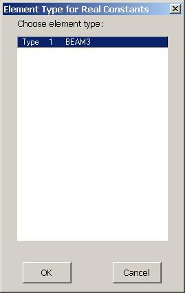
14 Real Constants Geometric modeling 14
15 Real Constants Element real constants are properties that depend on the element type, such as cross-sectional properties of a beam element e.g. real constants for BEAM3, the 2-D beam element, are area (AREA), moment of inertia (IZZ), height (HEIGHT), shear deflection constant (SHEARZ), initial strain (ISTRN), and added mass per unit length (ADDMAS). Not all element types require real constants, and different elements of the same type may have different real constant values. Geometric modeling 15
16 Real Constants For line and area elements that require geometry data (cross-sectional area, thickness, diameter, etc.) to be specified as real constants, you can verify the input graphically by using the following commands in the order shown: ANSYS displays the elements as solid elements, using a rectangular cross-section for link and shell elements and a circular cross-section for pipe elements. The crosssection proportions are determined from the real constant values. Utility Menu> PlotCtrls> Style> Size and Shape Utility Menu> Plot> Elements Geometric modeling 16
 or their GUI path equivalents to define and use cross sections in your models.")
17 Sections Building a model using BEAM44, BEAM188, or BEAM189, you can use the section commands (SECTYPE, SECDATA, etc.) or their GUI path equivalents to define and use cross sections in your models. Geometric modeling 17
18 Sections A cross section defines the geometry of the beam in a plane perpendicular to the beam axial direction. ANSYS supplies a library of eleven commonly-used beam cross section shapes, and permits user-defined cross section shapes. When a cross section is defined, ANSYS builds a numeric model using a nine node cell for determining the properties (Iyy, Izz, etc.) of the section and for the solution to the Poisson's equation for torsional behaviour. Geometric modeling 18
19 Sections Geometric modeling 19
20 Geometry/Modelling Creating a solid model within ANSYS. Using direct generation. Importing a model created in a computeraided design (CAD) system. Geometric modeling 20
21 Coordinate systems Global and local coordinate systems are used to locate geometry items (nodes, keypoints, etc.) in space. The display coordinate system determines the system in which geometry items are listed or displayed. The nodal coordinate system defines the degree of freedom directions at each node and the orientation of nodal results data. The element coordinate system determines the orientation of material properties and element results data. The results coordinate system is used to transform nodal or element results data to a particular coordinate system for listings, displays, or general postprocessing operations (POST1). The working plane, which is separate from the coordinate systems discussed in this chapter, is used to locate geometric primitives during the modeling process. Geometric modeling 21
22 Coordinate systems (a) Cartesian (X, Y, Z components) coordinate system 0 (C.S.0) (b) Cylindrical (R, θ, Z components) coordinate system 1 (C.S.1) (c) Spherical (R, θ, φ components) coordinate system 2 (C.S.2) (d) Cylindrical (R, θ, Y components) coordinate system 5 (C.S.5) Geometric modeling 22

23 z Modeling (coordinates) Cartesian z Cylindrical z Spherical (x,y,z) (r,θ,z) φ (r,θ,φ) z x y x θ r y x θ r y General Curvilinear Coordinates General orthogonal Coordinates Geometric modeling 23

24 Geometry/Modelling Create geometrical entities Operate perform Boolean operations Move / Modify move or modify geometrical entities Copy copy geometrical entities Delete geometrical entities Update Geom update the geometry in relation to for example buckling analysis Geometric modeling 24
 Areas (and Solid-Model Surface Loads) Lines (and Solid-Model Line Loads) Keypoints (and Solid-Model Point Loads) Geometric")
25 Modeling - Create The hierarchy of modeling entities is as listed below: Elements (and Element Loads) Nodes (and Nodal Loads) Volumes (and Solid-Model Body Loads) Areas (and Solid-Model Surface Loads) Lines (and Solid-Model Line Loads) Keypoints (and Solid-Model Point Loads) Geometric modeling 25

26 Modeling - Operate Perform geometrical operations in order to obtain new geometrical entities Geometric modeling 26
27 Modeling - Move/Modify Move or modify locations or sizes of geometrical entities Geometric modeling 27

28 Modeling - Copy Copy geometrical entities to new geometrical entities with new locations Geometric modeling 28
 Areas (and Solid-Model Surface Loads) Lines (and Solid-Model Line Loads) Keypoints (and Solid-Model Point Loads) Geometric")
29 Modeling - Delete The hierarchy of modeling entities is as listed below: Elements (and Element Loads) Nodes (and Nodal Loads) Volumes (and Solid-Model Body Loads) Areas (and Solid-Model Surface Loads) Lines (and Solid-Model Line Loads) Keypoints (and Solid-Model Point Loads) Geometric modeling 29

30 Modeling - Update Geom Adds displacements from a previous analysis and updates the geometry of the finite element model to the deformed configuration. Geometric modeling 30


31 Create Keypoints (In Active CS) It is a good idea to use keypoints as reference points in the modeling phase Geometric modeling 31


32 Create Lines (Straight Line) Geometric modeling 32

33 Create Lines - Arcs Geometric modeling 33
 Geometric")
34 Create Areas (By 2 Corners) Geometric modeling 34
 Geometric")
35 Create Areas (By dimensions) Geometric modeling 35
 Geometric")
36 Create Areas (By Lines) Geometric modeling 36


37 Create - Volumes Geometric modeling 37
38 Booleans - Intersect LINL (Line Intersect Line) AINA (Area Intersect Area) Geometric modeling 38
39 Booleans - Intersect VINV (Volume Intersect Volume) LINA (Line Intersect Area) Geometric modeling 39
40 Booleans - Intersect LINV (Line Intersect Volume) AINV (Area Intersect Volume) Geometric modeling 40
41 Booleans - Add AADD (Add Areas) VADD (Add Volumes) Geometric modeling 41
42 Booleans - Subtract LSBL (Line Subtract Line) ASBA (Area Subtract Area) Geometric modeling 42
43 Booleans - Subtract VSBV (Volume Subtract Volume) LSBA (Line Subtract Area) Geometric modeling 43
44 Booleans - Subtract LSBV (Line Subtract Volume) ASBV (Area Subtract Volume) Geometric modeling 44
45 Booleans - Subtract ASBL (Area Subtract Line) VSBA (Volume Subtract Area) Geometric modeling 45
46 Booleans - Overlap LOVLAP (Line Overlap Line) AOVLAP (Area Overlap Area) VOVLAP (Volume Overlap Volume) Geometric modeling 46
47 Booleans - Glue LGLUE (Line Glue Line) AGLUE (Area Glue Area) VGLUE (Volume Glue Volume) Geometric modeling 47

48 Mesh Generation Approaches Structured discretization Mapped meshing Unstructured discretization Free meshing Geometric modeling 48
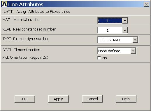
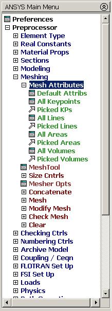
49 Mesh Attributes Geometric modeling 49


50 Meshing Size Cntrls Geometric modeling 50


51 Meshing - ManualSize Geometric modeling 51


52 Meshing - Lines Geometric modeling 52

53 Meshing - Clear Deletes nodes and area elements associated with selected lines, areas, or volumes. Geometric modeling 53
Course in ANSYS. Example Truss 2D. Example0150
 Course in ANSYS Example0150 Example Truss 2D Objective: Compute the maximum deflection Tasks: Display the deflection figure? Topics: Topics: Start of analysis, Element type, Real constants, Material, modeling,
Course in ANSYS. Example0500. ANSYS Computational Mechanics, AAU, Esbjerg
 Course in Example0500 Example Column beam Objective: Compute the critical buckling load and display the mode shape Tasks: Create a table and compare results with results obtained from buckling theory?
Structural static analysis - Analyzing 2D frame
 Structural static analysis - Analyzing 2D frame In this tutorial we will analyze 2D frame (see Fig.1) consisting of 2D beams with respect to resistance to two different kinds of loads: (a) the downward
Exercise 1. 3-Point Bending Using the GUI and the Bottom-up-Method
 Exercise 1 3-Point Bending Using the GUI and the Bottom-up-Method Contents Learn how to... 1 Given... 2 Questions... 2 Taking advantage of symmetries... 2 A. Preprocessor (Setting up the Model)... 3 A.1
NonLinear Analysis of a Cantilever Beam
 NonLinear Analysis of a Cantilever Beam Introduction This tutorial was created using ANSYS 7.0 The purpose of this tutorial is to outline the steps required to do a simple nonlinear analysis of the beam
Structural static analysis - Analyzing 2D frame
 Structural static analysis - Analyzing 2D frame In this tutorial we will analyze 2D frame (see Fig.1) consisting of 2D beams with respect to resistance to two different kinds of loads: (a) the downward
ECE421: Electronics for Instrumentation
 ECE421: Electronics for Instrumentation Lecture #8: Introduction to FEA & ANSYS Mostafa Soliman, Ph.D. March 23 rd 2015 Mostafa Soliman, Ph.D. 1 Outline Introduction to Finite Element Analysis Introduction
Example Plate with a hole
 Course in ANSYS Example Plate with a hole A Objective: Determine the maximum stress in the x-direction for point A and display the deformation figure Tasks: Create a submodel to increase the accuracy of
ANSYS Element. elearning. Peter Barrett October CAE Associates Inc. and ANSYS Inc. All rights reserved.
 ANSYS Element Selection elearning Peter Barrett October 2012 2012 CAE Associates Inc. and ANSYS Inc. All rights reserved. ANSYS Element Selection What is the best element type(s) for my analysis? Best
Chapter 3 Analysis of Original Steel Post
 Chapter 3. Analysis of original steel post 35 Chapter 3 Analysis of Original Steel Post This type of post is a real functioning structure. It is in service throughout the rail network of Spain as part
Element Order: Element order refers to the interpolation of an element s nodal results to the interior of the element. This determines how results can
 TIPS www.ansys.belcan.com 鲁班人 (http://www.lubanren.com/weblog/) Picking an Element Type For Structural Analysis: by Paul Dufour Picking an element type from the large library of elements in ANSYS can be
Dhanalakshmi College Of Engineering
 Dhanalakshmi College Of Engineering Manimangalam, Tambaram, Chennai 601 301 DEPARTMENT OF MECHANICAL ENGINEERING ME 6711 SIMULATION AND ANALYSIS LABORATORY VII SEMESTER - R 2013 LABORATORY MANUAL Name
Two Dimensional Truss
 Two Dimensional Truss Introduction This tutorial was created using ANSYS 7.0 to solve a simple 2D Truss problem. This is the first of four introductory ANSYS tutorials. Problem Description Determine the
Module 1: Introduction to Finite Element Analysis. Lecture 4: Steps in Finite Element Analysis
 25 Module 1: Introduction to Finite Element Analysis Lecture 4: Steps in Finite Element Analysis 1.4.1 Loading Conditions There are multiple loading conditions which may be applied to a system. The load
CITY AND GUILDS 9210 UNIT 135 MECHANICS OF SOLIDS Level 6 TUTORIAL 15 - FINITE ELEMENT ANALYSIS - PART 1
 Outcome 1 The learner can: CITY AND GUILDS 9210 UNIT 135 MECHANICS OF SOLIDS Level 6 TUTORIAL 15 - FINITE ELEMENT ANALYSIS - PART 1 Calculate stresses, strain and deflections in a range of components under
ANSYS 5.6 Tutorials Lecture # 2 - Static Structural Analysis
 R50 ANSYS 5.6 Tutorials Lecture # 2 - Static Structural Analysis Example 1 Static Analysis of a Bracket 1. Problem Description: The objective of the problem is to demonstrate the basic ANSYS procedures
Module: 2 Finite Element Formulation Techniques Lecture 3: Finite Element Method: Displacement Approach
 11 Module: 2 Finite Element Formulation Techniques Lecture 3: Finite Element Method: Displacement Approach 2.3.1 Choice of Displacement Function Displacement function is the beginning point for the structural
Course in ANSYS. Example0505. ANSYS Computational Mechanics, AAU, Esbjerg
 Course in Example0505 Example Plate Objective: Compute the buckling load Tasks: How should this be modelled? Compare results with results obtained from norm calculations? Topics: Element type, Real constants,
CHAPTER 5 FINITE ELEMENT METHOD
 CHAPTER 5 FINITE ELEMENT METHOD 5.1 Introduction to Finite Element Method Finite element analysis is a computer based numerical method to deduce engineering structures strength and behaviour. Its use can
Module 1.2: Moment of a 1D Cantilever Beam
 Module 1.: Moment of a 1D Cantilever Beam Table of Contents Page Number Problem Description Theory Geometry Preprocessor 6 Element Type 6 Real Constants and Material Properties 7 Meshing 9 Loads 10 Solution
Guidelines for proper use of Plate elements
 Guidelines for proper use of Plate elements In structural analysis using finite element method, the analysis model is created by dividing the entire structure into finite elements. This procedure is known
NonLinear Materials AH-ALBERTA Web:
 NonLinear Materials Introduction This tutorial was completed using ANSYS 7.0 The purpose of the tutorial is to describe how to include material nonlinearities in an ANSYS model. For instance, the case
Structural modal analysis - 2D frame
 Structural modal analysis - 2D frame Determine the first six vibration characteristics, namely natural frequencies and mode shapes, of a structure depicted in Fig. 1, when Young s modulus= 27e9Pa, Poisson
Institute of Mechatronics and Information Systems
 EXERCISE 4 Free vibrations of an electrical machine model Target Getting familiar with the fundamental issues of free vibrations analysis of a simplified model of an electrical machine, with the use of
SAMCEF for ROTORS. Chapter 3.2: Rotor modeling. This document is the property of SAMTECH S.A. MEF A, Page 1
 SAMCEF for ROTORS Chapter 3.2: Rotor modeling This document is the property of SAMTECH S.A. MEF 101-03-2-A, Page 1 Table of contents Introduction Introduction 1D Model 2D Model 3D Model 1D Models: Beam-Spring-
Structural modal analysis - 2D frame
 Structural modal analysis - 2D frame Determine the first six vibration characteristics, namely natural frequencies and mode shapes, of a structure depicted in Fig. 1, when Young s modulus= 27e9Pa, Poisson
MAE Advanced Computer Aided Design. 01. Introduction Doc 02. Introduction to the FINITE ELEMENT METHOD
 MAE 656 - Advanced Computer Aided Design 01. Introduction Doc 02 Introduction to the FINITE ELEMENT METHOD The FEM is A TOOL A simulation tool The FEM is A TOOL NOT ONLY STRUCTURAL! Narrowing the problem
Example Cantilever beam
 Course in ANSYS Example0300 Example Cantilever beam Objective: Compute the maximum deflection and locate point of maximum deflection Tasks: How should this be modelled? Compare results with results obtained
Lecture 3 : General Preprocessing. Introduction to ANSYS Mechanical Release ANSYS, Inc. February 27, 2015
 Lecture 3 : General Preprocessing 16.0 Release Introduction to ANSYS Mechanical 1 2015 ANSYS, Inc. February 27, 2015 Chapter Overview In this chapter we cover basic preprocessing operations that are common
Release 10. Kent L. Lawrence. Mechanical and Aerospace Engineering University of Texas at Arlington SDC PUBLICATIONS
 ANSYS Release 10 Tutorial Kent L. Lawrence Mechanical and Aerospace Engineering University of Texas at Arlington SDC PUBLICATIONS Schroff Development Corporation www.schroff.com www.schroff-europe.com
TWO-DIMENSIONAL PROBLEM OF THE THEORY OF ELASTICITY. INVESTIGATION OF STRESS CONCENTRATION FACTORS.
 Ex_1_2D Plate.doc 1 TWO-DIMENSIONAL PROBLEM OF THE THEORY OF ELASTICITY. INVESTIGATION OF STRESS CONCENTRATION FACTORS. 1. INTRODUCTION Two-dimensional problem of the theory of elasticity is a particular
ANSYS Tutorial Release 11.0
 ANSYS Tutorial Release 11.0 Structural & Thermal Analysis Using the ANSYS Release 11.0 Environment Kent L. Lawrence Mechanical and Aerospace Engineering University of Texas at Arlington SDC PUBLICATIONS
Torsional-lateral buckling large displacement analysis with a simple beam using Abaqus 6.10
 Torsional-lateral buckling large displacement analysis with a simple beam using Abaqus 6.10 This document contains an Abaqus tutorial for performing a buckling analysis using the finite element program
Geometric Modeling. Introduction
 Geometric Modeling Introduction Geometric modeling is as important to CAD as governing equilibrium equations to classical engineering fields as mechanics and thermal fluids. intelligent decision on the
Bell Crank. Problem: Joseph Shigley and Charles Mischke. Mechanical Engineering Design 5th ed (New York: McGraw Hill, May 2002) page 87.
 page 87.") Problem: A cast-iron bell-crank lever, depicted in the figure below is acted upon by forces F 1 of 250 lb and F 2 of 333 lb. The section A-A at the central pivot has a curved inner surface with a radius
Problem: A cast-iron bell-crank lever, depicted in the figure below is acted upon by forces F 1 of 250 lb and F 2 of 333 lb. The section A-A at the central pivot has a curved inner surface with a radius
CHAPTER 6 EXPERIMENTAL AND FINITE ELEMENT SIMULATION STUDIES OF SUPERPLASTIC BOX FORMING
 113 CHAPTER 6 EXPERIMENTAL AND FINITE ELEMENT SIMULATION STUDIES OF SUPERPLASTIC BOX FORMING 6.1 INTRODUCTION Superplastic properties are exhibited only under a narrow range of strain rates. Hence, it
Finite Element Method. Chapter 7. Practical considerations in FEM modeling
 Finite Element Method Chapter 7 Practical considerations in FEM modeling Finite Element Modeling General Consideration The following are some of the difficult tasks (or decisions) that face the engineer
Chapter 7 Practical Considerations in Modeling. Chapter 7 Practical Considerations in Modeling
 CIVL 7/8117 1/43 Chapter 7 Learning Objectives To present concepts that should be considered when modeling for a situation by the finite element method, such as aspect ratio, symmetry, natural subdivisions,
Module 3: Buckling of 1D Simply Supported Beam
 Module : Buckling of 1D Simply Supported Beam Table of Contents Page Number Problem Description Theory Geometry 4 Preprocessor 7 Element Type 7 Real Constants and Material Properties 8 Meshing 9 Solution
Chapter 5 Modeling and Simulation of Mechanism
 Chapter 5 Modeling and Simulation of Mechanism In the present study, KED analysis of four bar planar mechanism using MATLAB program and ANSYS software has been carried out. The analysis has also been carried
Course in ANSYS. Example0504. ANSYS Computational Mechanics, AAU, Esbjerg
 Course in Example0504 Example Cantilever beam Objective: Compute the buckling load Tasks: Display the deflection figure? Topics: Topics: Start of analysis, Element type, Real constants, Material, modeling,
CHAPTER 1. Introduction
 ME 475: Computer-Aided Design of Structures 1-1 CHAPTER 1 Introduction 1.1 Analysis versus Design 1.2 Basic Steps in Analysis 1.3 What is the Finite Element Method? 1.4 Geometrical Representation, Discretization
Revised Sheet Metal Simulation, J.E. Akin, Rice University
 Revised Sheet Metal Simulation, J.E. Akin, Rice University A SolidWorks simulation tutorial is just intended to illustrate where to find various icons that you would need in a real engineering analysis.
5. Shell Reinforcement According To Eurocode 2
 5. Shell Reinforcement According To Eurocode Applicable CivilFEM Product: All CivilFEM Products Level of Difficulty: Moderate Interactive Time Required: 5 minutes Discipline: Concrete Shell Reinforcement
Generative Part Structural Analysis Fundamentals
 CATIA V5 Training Foils Generative Part Structural Analysis Fundamentals Version 5 Release 19 September 2008 EDU_CAT_EN_GPF_FI_V5R19 About this course Objectives of the course Upon completion of this course
Settlement of a circular silo foundation
 Engineering manual No. 22 Updated: 02/2018 Settlement of a circular silo foundation Program: FEM File: Demo_manual_22.gmk The objective of this manual is to describe the solution to a circular silo foundation
Strain-Based Finite Element Analysis of Stiffened Cylindrical Shell Roof
 American Journal of Civil Engineering 2017; 5(4): 225-230 http://www.sciencepublishinggroup.com/j/ajce doi: 10.11648/j.ajce.20170504.15 ISSN: 2330-8729 (Print); ISSN: 2330-8737 (Online) Strain-Based Finite
Statically Indeterminate Beam
 Problem: Using Castigliano's Theorem, determine the deflection at point A. Neglect the weight of the beam. W 1 N/m B 5 cm H 1 cm 1.35 m Overview Anticipated time to complete this tutorial: 45 minutes Tutorial
ANSYS. Geometry. Material Properties. E=2.8E7 psi v=0.3. ansys.fem.ir Written By:Mehdi Heydarzadeh Page 1
 Attention: This tutorial is outdated, you will be redirected automatically to the new site. If you are not redirected, click this link to the confluence site. Problem Specification Geometry Material Properties
Types of Idealizations. Idealizations. Cylindrical Shaped Part. Cyclic Symmetry. 3D Shell Model. Axisymmetric
 Types of Idealizations Idealizations Selecting the model type 3D Solid Plane Stress Plane Strain 3D Shell Beam Cyclic Symmetry Cylindrical Shaped Part Interior Pressure Load 3D model can be used to model
Course in ANSYS. Example0154. ANSYS Computational Mechanics, AAU, Esbjerg
 Course in Example0154 Example Frame 2D E = 210000N/mm 2 n = 0.3 L= 1000mm H = 1000mm a = 20mm b = 50mm c = 400mm F = 10000N I = 208333N/mm 4 Example0154 2 Example Frame 2D Objective: Compute the maximum
Exercise 1. 3-Point Bending Using the Static Structural Module of. Ansys Workbench 14.0
 Exercise 1 3-Point Bending Using the Static Structural Module of Contents Ansys Workbench 14.0 Learn how to...1 Given...2 Questions...2 Taking advantage of symmetries...2 A. Getting started...3 A.1 Choose
Ansys Mechanical APDL
 Ansys Mechanical APDL Day 1: FEA and ANSYS 9.00 12.00 About ANSYS, What is FEA?, Instructor Example Getting Started 12.00 1.00 Interactive Vs. Batch Mode, Starting ANSYS, Product Launcher, ANSYS Workbench,
Non-Linear Finite Element Methods in Solid Mechanics Attilio Frangi, Politecnico di Milano, February 3, 2017, Lesson 1
 Non-Linear Finite Element Methods in Solid Mechanics Attilio Frangi, attilio.frangi@polimi.it Politecnico di Milano, February 3, 2017, Lesson 1 1 Politecnico di Milano, February 3, 2017, Lesson 1 2 Outline
Learning Module 8 Shape Optimization
 Learning Module 8 Shape Optimization What is a Learning Module? Title Page Guide A Learning Module (LM) is a structured, concise, and self-sufficient learning resource. An LM provides the learner with
Module 1.5: Moment Loading of a 2D Cantilever Beam
 Module 1.5: Moment Loading of a D Cantilever Beam Table of Contents Page Number Problem Description Theory Geometry 4 Preprocessor 7 Element Type 7 Real Constants and Material Properties 8 Meshing 9 Loads
ANSYS AIM Tutorial Structural Analysis of a Plate with Hole
 ANSYS AIM Tutorial Structural Analysis of a Plate with Hole Author(s): Sebastian Vecchi, ANSYS Created using ANSYS AIM 18.1 Problem Specification Pre-Analysis & Start Up Analytical vs. Numerical Approaches
Appendix B: Creating and Analyzing a Simple Model in Abaqus/CAE
 Getting Started with Abaqus: Interactive Edition Appendix B: Creating and Analyzing a Simple Model in Abaqus/CAE The following section is a basic tutorial for the experienced Abaqus user. It leads you
Course in ANSYS. Example0152. ANSYS Computational Mechanics, AAU, Esbjerg
 Course in Example0152 Example Truss 2D E = 210e09N/m 2 n = 0.3 L1 = L2 = L3 = 3.6m H = 3.118m a = b = 0.050mm F1 = 280kN F2 = 210kN F3 = 280kN F4 = 360kN Example0152 2 Example Truss 2D Objective: Compute
General modeling guidelines
 General modeling guidelines Some quotes from industry FEA experts: Finite element analysis is a very powerful tool with which to design products of superior quality. Like all tools, it can be used properly,
Module 1.6: Distributed Loading of a 2D Cantilever Beam
 Module 1.6: Distributed Loading of a 2D Cantilever Beam Table of Contents Page Number Problem Description 2 Theory 2 Geometry 4 Preprocessor 7 Element Type 7 Real Constants and Material Properties 8 Meshing
2: Static analysis of a plate
 2: Static analysis of a plate Topics covered Project description Using SolidWorks Simulation interface Linear static analysis with solid elements Finding reaction forces Controlling discretization errors
SDC. Engineering Analysis with COSMOSWorks. Paul M. Kurowski Ph.D., P.Eng. SolidWorks 2003 / COSMOSWorks 2003
 Engineering Analysis with COSMOSWorks SolidWorks 2003 / COSMOSWorks 2003 Paul M. Kurowski Ph.D., P.Eng. SDC PUBLICATIONS Design Generator, Inc. Schroff Development Corporation www.schroff.com www.schroff-europe.com
Course in ANSYS. Example0153. ANSYS Computational Mechanics, AAU, Esbjerg
 Course in Example0153 Example Offshore structure F Objective: Display the deflection figure and von Mises stress distribution Tasks: Import geometry from IGES. Display the deflection figure? Display the
Topology Optimization for Designers
 TM Topology Optimization for Designers Siemens AG 2016 Realize innovation. Topology Optimization for Designers Product Features Uses a different approach than traditional Topology Optimization solutions.
COMPUTER AIDED ENGINEERING. Part-1
 COMPUTER AIDED ENGINEERING Course no. 7962 Finite Element Modelling and Simulation Finite Element Modelling and Simulation Part-1 Modeling & Simulation System A system exists and operates in time and space.
Ansys Lab Frame Analysis
 Ansys Lab Frame Analysis Analyze the highway overpass frame shown in Figure. The main horizontal beam is W24x162 (area = 47.7 in 2, moment of inertia = 5170 in 4, height = 25 in). The inclined members
Creo Simulate 3.0 Tutorial
 Creo Simulate 3.0 Tutorial Structure and Thermal Roger Toogood, Ph.D., P. Eng. SDC PUBLICATIONS Better Textbooks. Lower Prices. www.sdcpublications.com Powered by TCPDF (www.tcpdf.org) Visit the following
Introduction to Finite Element Analysis using ANSYS
 Introduction to Finite Element Analysis using ANSYS Sasi Kumar Tippabhotla PhD Candidate Xtreme Photovoltaics (XPV) Lab EPD, SUTD Disclaimer: The material and simulations (using Ansys student version)
NUMERICAL COUPLING BETWEEN DEM (DISCRETE ELEMENT METHOD) AND FEA (FINITE ELEMENTS ANALYSIS).
 AND FEA (FINITE ELEMENTS ANALYSIS).") NUMERICAL COUPLING BETWEEN DEM (DISCRETE ELEMENT METHOD) AND FEA (FINITE ELEMENTS ANALYSIS). Daniel Schiochet Nasato - ESSS Prof. Dr. José Roberto Nunhez Unicamp Dr. Nicolas Spogis - ESSS Fabiano Nunes
NUMERICAL COUPLING BETWEEN DEM (DISCRETE ELEMENT METHOD) AND FEA (FINITE ELEMENTS ANALYSIS). Daniel Schiochet Nasato - ESSS Prof. Dr. José Roberto Nunhez Unicamp Dr. Nicolas Spogis - ESSS Fabiano Nunes
Chapter 6. Concept Modeling. ANSYS, Inc. Proprietary Inventory # May 11, ANSYS, Inc. All rights reserved.
 Chapter 6 Concept Modeling 6-1 Contents Concept Modeling Creating Line Bodies Modifying i Line Bodies Cross Sections Cross Section Alignment Cross Section Offset Surfaces From Lines Surfaces From Sketches
5. Finite Element Analysis of Bellows
 5. Finite Element Analysis of Bellows 5.1 Introduction: Traditional design process and stress analysis techniques are very specific for each individual case based on fundamental principles. It can only
PYTHON API TO RUN CALCULIX: PYCALCULIX Justin Black Mechanical Engineer
 PYTHON API TO RUN CALCULIX: PYCALCULIX 2014-12-22 Justin Black Mechanical Engineer Justin.a.black@gmail.com www.justinablack.com WHAT AND WHY What: I created an API in python to build, solve and analyze
Linear Bifurcation Buckling Analysis of Thin Plate
 LESSON 13a Linear Bifurcation Buckling Analysis of Thin Plate Objectives: Construct a quarter model of a simply supported plate. Place an edge load on the plate. Run an Advanced FEA bifurcation buckling
Similar Pulley Wheel Description J.E. Akin, Rice University
 Similar Pulley Wheel Description J.E. Akin, Rice University The SolidWorks simulation tutorial on the analysis of an assembly suggested noting another type of boundary condition that is not illustrated
ME 442. Marc/Mentat-2011 Tutorial-1
 ME 442 Overview Marc/Mentat-2011 Tutorial-1 The purpose of this tutorial is to introduce the new user to the MSC/MARC/MENTAT finite element program. It should take about one hour to complete. The MARC/MENTAT
Instructions for Muffler Analysis
 Instructions for Muffler Analysis Part 1: Create the BEM mesh using ANSYS Specify Element Type Preprocessor > Element Type > Add/Edit/Delete Add Shell Elastic 4 Node 181 Close Specify Geometry Preprocessor
Course in ANSYS. Example0410. ANSYS Computational Mechanics, AAU, Esbjerg
 Course in Example0410 Example Frame 2D Objective: Compute the harmonic response Tasks: Perform a modal analysis Display the mode shapes Perform a harmonic analysis Topics: Topics: Start of analysis, Element
Beams. Lesson Objectives:
 Beams Lesson Objectives: 1) Derive the member local stiffness values for two-dimensional beam members. 2) Assemble the local stiffness matrix into global coordinates. 3) Assemble the structural stiffness
SolidWorks. An Overview of SolidWorks and Its Associated Analysis Programs
 An Overview of SolidWorks and Its Associated Analysis Programs prepared by Prof. D. Xue University of Calgary SolidWorks - a solid modeling CAD tool. COSMOSWorks - a design analysis system fully integrated
Embedded Reinforcements
 Embedded Reinforcements Gerd-Jan Schreppers, January 2015 Abstract: This paper explains the concept and application of embedded reinforcements in DIANA. Basic assumptions and definitions, the pre-processing
PES Institute Of Technology Bangalore South Campus. Department of Mechanical Engineering
 PES Institute Of Technology Department of Mechanical Engineering Computer Aided Modeling & Analysis Laboratory Manual (Finite Element Method) For 6th Semester Mechanical Engineering Coordinator Mr. Madhu.
Multi-Step Analysis of a Cantilever Beam
 LESSON 4 Multi-Step Analysis of a Cantilever Beam LEGEND 75000. 50000. 25000. 0. -25000. -50000. -75000. 0. 3.50 7.00 10.5 14.0 17.5 21.0 Objectives: Demonstrate multi-step analysis set up in MSC/Advanced_FEA.
Introduction to ANSYS DesignModeler
 Lecture 5 Modeling 14. 5 Release Introduction to ANSYS DesignModeler 2012 ANSYS, Inc. November 20, 2012 1 Release 14.5 Preprocessing Workflow Geometry Creation OR Geometry Import Geometry Operations Meshing
ES 230 Strengths Intro to Finite Element Modeling & Analysis Homework Assignment 2
 ES 230 Strengths Intro to Finite Element Modeling & Analysis Homework Assignment 2 In this homework assignment you will use your rapidly developing ANSYS skill set to model and analyze three different
Creating and Analyzing a Simple Model in Abaqus/CAE
 Appendix B: Creating and Analyzing a Simple Model in Abaqus/CAE The following section is a basic tutorial for the experienced Abaqus user. It leads you through the Abaqus/CAE modeling process by visiting
Computer modelling and simulation of the mechanical response of composite lattice structures
 22nd International Congress on Modelling and Simulation, Hobart, Tasmania, Australia, 3 to 8 December 2017 mssanz.org.au/modsim2017 Computer modelling and simulation of the mechanical response of composite
Chapter 2. Structural Tutorial
 Chapter 2. Structural Tutorial Tutorials> Chapter 2. Structural Tutorial Static Analysis of a Corner Bracket Problem Specification Problem Description Build Geometry Define Materials Generate Mesh Apply
ANSYS Tutorials. Table of Contents. Grady Lemoine
 ANSYS Tutorials Grady Lemoine Table of Contents Example 1: 2-D Static Stress Analysis in ANSYS...2 Example 2: 3-D Static Stress Analysis...5 Example 3: 2-D Frame With Multiple Materials and Element Types...10
Spatial Variation of Physical Properties
 LESSON 5 Spatial Variation of Physical Properties Aluminum Steel 45 Radius 1 Radius 3 Radius 4 Objective: To model the variation of physical properties as a function of spatial coordinates. MSC/NASTRAN
This document contains the draft version of the following paper:
 This document contains the draft version of the following paper: M. Karnik, S.K. Gupta, and E.B. Magrab. Geometric algorithms for containment analysis of rotational parts. Computer Aided Design, 37(2):213-230,
Topology and Boundary Representation. The ACIS boundary representation (B-rep) of a model is a hierarchical decomposition of the model s topology:
 of a model is a hierarchical decomposition of the model s topology:") Chapter 6. Model Topology Topology refers to the spatial relationships between the various entities in a model. Topology describes how geometric entities are connected (connectivity). On its own, topology
Chapter 6. Model Topology Topology refers to the spatial relationships between the various entities in a model. Topology describes how geometric entities are connected (connectivity). On its own, topology
file://c:\documents and Settings\sala\Configuración local\temp\~hha54f.htm
 Página 1 de 26 Tutorials Chapter 2. Structural Tutorial 2.1. Static Analysis of a Corner Bracket 2.1.1. Problem Specification Applicable ANSYS Products: Level of Difficulty: Interactive Time Required:
CHAPTER 8 FINITE ELEMENT ANALYSIS
 If you have any questions about this tutorial, feel free to contact Wenjin Tao (w.tao@mst.edu). CHAPTER 8 FINITE ELEMENT ANALYSIS Finite Element Analysis (FEA) is a practical application of the Finite
359. Parametrization-based shape optimization of shell structures in the case of free vibrations
 359. Parametrization-based shape optimization of shell structures in the case of free vibrations D. Dagys 1, V. Ostasevicius 2, R. Gaidys 3 1,2,3 Kaunas University of Technology, K. Donelaicio 73, LT-44029,
Crutch Redesign. ME 4041 Final Project. Group 5. Michael Notarnicola. Matt Karesh. Stuart Boyer
 Crutch Redesign ME 4041 Final Project Group 5 Michael Notarnicola Matt Karesh Stuart Boyer 0 Contents PROBLEM STATEMENT:... 2 PROJECT OVERVIEW AND MOTIVATION:... 2 SUBASSEMBLIES:... 3 FOOT:... 3 SHIN:...
MAE 323: Lecture 6. Modeling Topics: Part I. Modeling Topics Alex Grishin MAE 323 Lecture 6 FE Modeling Topics: Part 1
 Modeling Topics 1 Common element types for structural analyis: oplane stress/strain, Axisymmetric obeam, truss,spring oplate/shell elements o3d solid ospecial: Usually used for contact or other constraints
Introduction to ANSYS DesignModeler
 Lecture 9 Beams and Shells 14. 5 Release Introduction to ANSYS DesignModeler 2012 ANSYS, Inc. November 20, 2012 1 Release 14.5 Beams & Shells The features in the Concept menu are used to create and modify
Femap Version
 Femap Version 11.3 Benefits Easier model viewing and handling Faster connection definition and setup Faster and easier mesh refinement process More accurate meshes with minimal triangle element creation
THREE DIMENSIONAL ACES MODELS FOR BRIDGES
 THREE DIMENSIONAL ACES MODELS FOR BRIDGES Noel Wenham, Design Engineer, Wyche Consulting Joe Wyche, Director, Wyche Consulting SYNOPSIS Plane grillage models are widely used for the design of bridges,