Best Practices: Volume Meshing Kynan Maley
|
|
|
- Melanie Bruce
- 6 years ago
- Views:
Transcription

1 Best Practices: Volume Meshing Kynan Maley
2 Volume Meshing Volume meshing is the basic tool that allows the creation of the space discretization needed to solve most of the CAE equations for: CFD Stress Analysis Heat transfer Electro-Chemistry Magneto Hydro Dynamics...


3 Pipeline Meshing Pipeline meshing allows you to: Change geometry, mesh type, refinements, location/number of prism layers, etc. Automatically update the mesh and map the old solution Rapidly evaluate multiple designs Solution mapping Make changes to the geometry and mesh while retaining your solution Physics is independent of mesh Wrapper Remesher Polyhedral Mesher Trim Cell Mesher Prism Layer Surface Preparation / Meshing Volume Mesh Generation 3


4 Volume Meshing in STAR-CCM+ General Purpose 3D Meshers: Polyhedral Trimmer Tet Mesher General purpose meshers on special geometries tend to produce non optimal meshes in terms of: Cell count Quality

 Meshers: Prism Layer Mesher Extruder Thin Mesher")
5 Volume Meshing in STAR-CCM+ Examples of special geometries: Thin objects/parts Extruded parts Long or curved pipes/ducts Specialized (2.5D) Meshers: Prism Layer Mesher Extruder Thin Mesher Generalized Cylinder Mesher Advancing Layer Mesher

6 Volume Meshing in STAR-CCM+ 2.5D meshing is a synthetic definition of those meshing techniques that exploit the fact that certain special geometries have a general mesh in 2 dimensions while in the 3 rd dimension the mesh has some form of simplification: Extruded in a predetermined direction Extruded along the local normal direction Swept along a 3d curve or axis

7 Volume Meshing in STAR-CCM+ Full volume meshing pipeline is parallel poly mesher Reducing memory and wall time
8 Volume Meshing Golden rule of volume meshing in STAR-CCM+ Volume meshers have requirements for the input surface: Closed Manifold Non-intersecting Often cell quality issues in the volume mesh can be tracked down to face quality issues in the surface mesh Recommendation is to use the Surface Remesher always prior to volume meshing (with same size settings)

9 Volume Meshing Surface Mesh Quality of CAD determines path to closed, manifold, non intersecting surface The surface wrapper is used for the worst quality CAD Also useful for de-featuring your model Other methods exist to fix minor CAD issues


10 General Purpose Mesher Polyhedral - Trimmer Polyhedral mesher General purpose, reliable, robust Capable of multi-region conformal meshing Suitable for Conjugate Heat Transfer simulations Trimmer Fast and high quality Anisotropic refinement Perfect for large domains such as: Cars in wind tunnels Airplanes Ships Trains
 Can be done in a local coordinate system, allowing alignment with flow")
11 General Purpose Mesher Trimmer Mesher Rule of thumb here is to use a trimmed mesh for cases that have large cartesian aligned flow directions Also useful when Trimmer Wake Refinement is needed (refinement follows shape of boundary) Can be done in a local coordinate system, allowing alignment with flow direction


12 General Purpose Mesher Refinement using Volumetric Controls In many situations it is desirable to have the possibility to accurately control the mesh size High gradient zones Shocks High error zones This can be accomplished by placing appropriate Volumetric Controls

 Prism")
13 General Purpose Mesher Refinement using Volumetric Controls Volumetric Controls allow a number of refinement types: Surface Mesh Volume Mesh Isotropic Anisotropic (Trimmer) Prism Layer Mesh


14 General Purpose Mesher Refinement using Boundaries and Feature Curves Surface mesh size can be set at individual Boundaries Feature Curves The volume mesh size is related to the surface size and growth rate
15 General Purpose Mesher Polyhedral Refinement Level Refinement levels provide a quick way to globally refine a polyhedral mesh Activated within the Polyhedral Mesher model settings One of two refinement levels selected in Reference Values Level 1: Splits each polyhedral cell into 6 or 7 new cells Level 2: Splits each polyhedral cell into 40 to 50 new cells Prism Layer unchanged


16 Volume Mesh Volume Ratio Avoid huge jumps in volume ratio, it will cause issues Keep the ratio as small as possible Prism layers can help improve blending from near wall to far field

17 Volume Mesh Volume Ratio - Trimmer The volume ratio for trimmed cells is influenced through different Growth Rate values On continuum level Trimmer > Properties: Template mesh growth rate Reference Values > Template Growth rate > Properties: Default Growth rate

18 Volume Mesh Volume Ratio - Trimmer On continuum, boundary and interface level Boundary growth rate It controls the rate of size changes between cells adjacent to surfaces and cells in the core


19 Volume Mesh Volume Ratio - Trimmer Example Template Growth Rate options Boundary Growth rate None Fast Very Slow Default Growth rate
20 Volume Mesh Prism Layer Mesher What are prism cells? A polyhedral base, a copy of it at top and rectangular sides connecting both Where are prism cells used? Wall Prism Layer (turbulence, heat transfer) Extruder Thin Mesher Advancing Layer Mesher


21 Wall Prism Layers Generation of Prism Layer Mesh The Prism Layer thickness is subtracted from the boundary Offset surface A core mesh is created The Prism Mesh is extruded to the boundary
22 Wall Prism Layers Locations of Prism Mesh Where are Prism Layers generated? Only at boundaries of type Wall Why is no Prism Layer created at my fluid-solid interface? Although the boundaries forming an interface are often of type Wall, being an interface overrules this setting: At an interface no prism layers will be generated as default

23 Wall Prism Layers Introduction to Properties Options With the recent releases of STAR-CCM+ the creation of boundary layers has been further improved Today I will show you some of the Model Properties with which to influence the prism mesh in narrow passages Gap Fill Percentage Minimum Thickness Percentage Layer Reduction Percentage


24 Wall Prism Layers Default 25% Default 10% Default 50% 10% 25% 85%


25 Wall Prism Layers Expert Settings
26 Additional Mesher Extruder The extruder meshing model performs an additional volume meshing step once the core mesh has been generated The model can be activated for any of the core mesh types and enabled for any boundary Care should be taken however that the extrusion volume will not interfere with the existing mesh by intersecting it in any way Generates prism cells which extends the confines of the starting surface Can use any coordinate system: Cartesian Cylindrical Spherical


27 Additional Mesher Extruder Extruder Mesher Options Frozen Boundaries Frozen Boundaries On Frozen Boundaries Off


28 Additional Mesher Extruder Example 1 Inflate the computational domain in all directions One possibility is to change the Part on the Geometry level Another is to extrude the outer boundaries without the Frozen Boundaries option


29 Additional Mesher Extruder Example 2 L 3L-8L


30 Additional Mesher Generalized Cylinder Generates an Extruded mesh along lengths of a part considered a cylinder Automatic cylinder detection


31 Advanced Mesher Thin Mesher The thin meshing model allows thin regions in the geometry to have a prismatic type volume mesh Reason is to improve the overall cell quality and reduce the cell count when compared to an equivalent tetrahedral or polyhedral type core mesh When very thin structures cannot be modeled using baffles their thickness must be modeled with a minimum of 3 cells through the thickness


32 Advanced Mesher Example - Thin Mesher


33 Advanced Mesher Advancing Layer The advancing layer produces prismatic cell layers near wall boundaries Extruding the cells from the surface into the region volume allows for a thicker layer with a more uniform distribution than the prism layer mesher


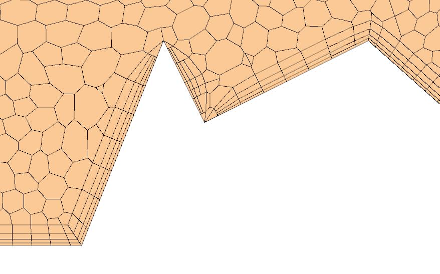
34 Advanced Mesher Advancing Layer Advancing Layer Options Two options for Stretching Function Several options for Stretching Mode To influence the advancing layer mesh at convex corners, refine the Feature Curve at this edge

35 Advanced Mesher Advancing Layer Example - Shuttle


36 Directed Mesher Directed meshing is a method for creating swept meshes from a 2D starting surface mesh The starting surface mesh may either be created by: Patching the surface and creating quadrahedral elements Using the surface of an existing volume mesh The surface is then swept along a path described by the CAD geometry This results in a high quality structured mesh Engine Powertrain Electric Machines


37 Overset Mesher Overset Meshing: A background mesh enclosing the whole solution domain Separate meshes enclosing each body The regions overlap, and flow-field information is passed between them No need to remesh during motion or after moving geometry!

38 Overset Mesher

39 Overset Mesher
40 Questions Any Questions?
Best Practices Workshop: Parts & Mesh-Based Operations
 Best Practices Workshop: Parts & Mesh-Based Operations Overview What are Parts and Mesh Based Operations? Transition from Region Based Meshing Why move to Parts Based Meshing How to use Parts Based Mesh
Contribution to GMGW-1
 Contribution to GMGW-1 Vivek Ahuja, Shaunak Pai, John Wilson, Rajesh Kumar, Michael Stubert Inc. (003) Restricted Siemens AG 2017 Realize innovation. Summary of meshes generated Star-CCM+ Geometry Core
Structured Grid Generation for Turbo Machinery Applications using Topology Templates
 Structured Grid Generation for Turbo Machinery Applications using Topology Templates January 13th 2011 Martin Spel martin.spel@rtech.fr page 1 Agenda: R.Tech activities Grid Generation Techniques Structured
Viscous Hybrid Mesh Generation
 Tutorial 4. Viscous Hybrid Mesh Generation Introduction In cases where you want to resolve the boundary layer, it is often more efficient to use prismatic cells in the boundary layer rather than tetrahedral
A new meshing methodology for faster simulation of a Body-In-White dipping process
 A new meshing methodology for faster simulation of a Body-In-White dipping process Madhusudhan Devanathan MBtech Group GmbH & Co. KGaA, Sindelfingen, Germany STAR Global Conference 19 1 March 01, Amsterdam
Meshing in STAR-CCM+: Recent Advances Aly Khawaja
 Meshing in STAR-CCM+: Recent Advances Aly Khawaja Outline STAR-CCM+: a complete simulation workflow Emphasis on pre-processing technology Recent advances in surface preparation and meshing Continue to
CDA Workshop Physical & Numerical Hydraulic Modelling. STAR-CCM+ Presentation
 CDA Workshop Physical & Numerical Hydraulic Modelling STAR-CCM+ Presentation ENGINEERING SIMULATION CFD FEA Mission Increase the competitiveness of companies through optimization of their product development
STAR-CCM+: Wind loading on buildings SPRING 2018
 STAR-CCM+: Wind loading on buildings SPRING 2018 1. Notes on the software 2. Assigned exercise (submission via Blackboard; deadline: Thursday Week 3, 11 pm) 1. NOTES ON THE SOFTWARE STAR-CCM+ generates
Free Convection Cookbook for StarCCM+
 ME 448/548 February 28, 2012 Free Convection Cookbook for StarCCM+ Gerald Recktenwald gerry@me.pdx.edu 1 Overview Figure 1 depicts a two-dimensional fluid domain bounded by a cylinder of diameter D. Inside
Best Practices Workshop: Overset Meshing
 Best Practices Workshop: Overset Meshing Overview Introduction to Overset Meshes Range of Application Workflow Demonstrations and Best Practices What are Overset Meshes? Overset meshes are also known as
Advances in Turbomachinery Simulation Fred Mendonça and material prepared by Chad Custer, Turbomachinery Technology Specialist
 Advances in Turbomachinery Simulation Fred Mendonça and material prepared by Chad Custer, Turbomachinery Technology Specialist Usage From Across the Industry Outline Key Application Objectives Conjugate
CFD VALIDATION FOR SURFACE COMBATANT 5415 STRAIGHT AHEAD AND STATIC DRIFT 20 DEGREE CONDITIONS USING STAR CCM+
 CFD VALIDATION FOR SURFACE COMBATANT 5415 STRAIGHT AHEAD AND STATIC DRIFT 20 DEGREE CONDITIONS USING STAR CCM+ by G. J. Grigoropoulos and I..S. Kefallinou 1. Introduction and setup 1. 1 Introduction The
Impact of STAR-CCM+ v7.0 in the Automotive Industry Frederick J. Ross, CD-adapco Director, Ground Transportation
 Impact of STAR-CCM+ v7.0 in the Automotive Industry Frederick J. Ross, CD-adapco Director, Ground Transportation Vehicle Simulation Components Vehicle Aerodynamics Design Studies Aeroacoustics Water/Dirt
Introduction to ANSYS DesignModeler
 Lecture 5 Modeling 14. 5 Release Introduction to ANSYS DesignModeler 2012 ANSYS, Inc. November 20, 2012 1 Release 14.5 Preprocessing Workflow Geometry Creation OR Geometry Import Geometry Operations Meshing
Advances in Pre-Processing
 Advances in Pre-Processing Laz Foley Confidence by Design Chicago June 14, 2012 1 Outline ANSYS DesignModeler Modeling Improvements ANSYS SpaceClaim Direct Modeler Workbench Integration and Model Preparation
Introduction to ANSYS ICEM CFD
 Lecture 4 Volume Meshing 14. 0 Release Introduction to ANSYS ICEM CFD 1 2011 ANSYS, Inc. March 21, 2012 Introduction to Volume Meshing To automatically create 3D elements to fill volumetric domain Generally
GEOMETRY MODELING & GRID GENERATION
 GEOMETRY MODELING & GRID GENERATION Dr.D.Prakash Senior Assistant Professor School of Mechanical Engineering SASTRA University, Thanjavur OBJECTIVE The objectives of this discussion are to relate experiences
Missile External Aerodynamics Using Star-CCM+ Star European Conference 03/22-23/2011
 Missile External Aerodynamics Using Star-CCM+ Star European Conference 03/22-23/2011 StarCCM_StarEurope_2011 4/6/11 1 Overview 2 Role of CFD in Aerodynamic Analyses Classical aerodynamics / Semi-Empirical
CFD simulation of a simplified model of the Sardinia Radio Telescope
 CFD simulation of a simplified model of the Sardinia Radio Telescope Stage Activities Report CRS4 July October 2017 Author G. Murtas Coordinators Vincent Moreau, Manuela Profir LIST OF CONTENT LIST OF
Automatic & Robust Meshing in Fluids 2011 ANSYS Regional Conferences
 Automatic & Robust Meshing in Fluids 2011 ANSYS Regional Conferences 1 This is just a taste Note that full 14.0 update webinars of an hour per product will be scheduled closer to the release This presentation
Metafor FE Software. 2. Operator split. 4. Rezoning methods 5. Contact with friction
 ALE simulations ua sus using Metafor eao 1. Introduction 2. Operator split 3. Convection schemes 4. Rezoning methods 5. Contact with friction 1 Introduction EULERIAN FORMALISM Undistorted mesh Ideal for
10.1 Overview. Section 10.1: Overview. Section 10.2: Procedure for Generating Prisms. Section 10.3: Prism Meshing Options
 Chapter 10. Generating Prisms This chapter describes the automatic and manual procedure for creating prisms in TGrid. It also discusses the solution to some common problems that you may face while creating
Recent Advances in Modelling Wind Parks in STAR CCM+ Steve Evans
 Recent Advances in Modelling Wind Parks in STAR CCM+ Steve Evans Introduction Company STAR-CCM+ Agenda Wind engineering at CD-adapco STAR-CCM+ & EnviroWizard Developments for Offshore Simulation CD-adapco:
Introduction to ANSYS FLUENT Meshing
 Workshop 02 Volume Fill Methods Introduction to ANSYS FLUENT Meshing 1 2011 ANSYS, Inc. December 21, 2012 I Introduction Workshop Description: Mesh files will be read into the Fluent Meshing software ready
Lecture 7: Mesh Quality & Advanced Topics. Introduction to ANSYS Meshing Release ANSYS, Inc. February 12, 2015
 Lecture 7: Mesh Quality & Advanced Topics 15.0 Release Introduction to ANSYS Meshing 1 2015 ANSYS, Inc. February 12, 2015 Overview In this lecture we will learn: Impact of the Mesh Quality on the Solution
Recent & Upcoming Features in STAR-CCM+ for Aerospace Applications Deryl Snyder, Ph.D.
 Recent & Upcoming Features in STAR-CCM+ for Aerospace Applications Deryl Snyder, Ph.D. Outline Introduction Aerospace Applications Summary New Capabilities for Aerospace Continuity Convergence Accelerator
Simulation of In-Cylinder Flow Phenomena with ANSYS Piston Grid An Improved Meshing and Simulation Approach
 Simulation of In-Cylinder Flow Phenomena with ANSYS Piston Grid An Improved Meshing and Simulation Approach Dipl.-Ing. (FH) Günther Lang, CFDnetwork Engineering Dipl.-Ing. Burkhard Lewerich, CFDnetwork
Automatic & Robust Meshing in Fluids 2011 ANSYS Regional Conferences
 Automatic & Robust Meshing in Fluids 2011 ANSYS Regional Conferences 1 Automatic & Robust Meshing Assembly Meshing Assembly Meshing enables dramatically reduced time to mesh for typical CAD models by eliminating
ANSYS ICEM CFD User's Manual
 ANSYS ICEM CFD User's Manual ANSYS, Inc. Southpointe 2600 ANSYS Drive Canonsburg, PA 15317 ansysinfo@ansys.com http://www.ansys.com (T) 724-746-3304 (F) 724-514-9494 Release 17.0 January 2016 ANSYS, Inc.
Validation of an Unstructured Overset Mesh Method for CFD Analysis of Store Separation D. Snyder presented by R. Fitzsimmons
 Validation of an Unstructured Overset Mesh Method for CFD Analysis of Store Separation D. Snyder presented by R. Fitzsimmons Stores Separation Introduction Flight Test Expensive, high-risk, sometimes catastrophic
Workshop 3: Cutcell Mesh Generation. Introduction to ANSYS Fluent Meshing Release. Release ANSYS, Inc.
 Workshop 3: Cutcell Mesh Generation 14.5 Release Introduction to ANSYS Fluent Meshing 1 2011 ANSYS, Inc. December 21, 2012 I Introduction Workshop Description: CutCell meshing is a general purpose meshing
3. MODELING A THREE-PIPE INTERSECTION (3-D)
") 3. MODELING A THREE-PIPE INTERSECTION (3-D) This tutorial employs primitives that is, predefined GAMBIT modeling components and procedures. There are two types of GAMBIT primitives: Geometry Mesh Geometry
3. MODELING A THREE-PIPE INTERSECTION (3-D) This tutorial employs primitives that is, predefined GAMBIT modeling components and procedures. There are two types of GAMBIT primitives: Geometry Mesh Geometry
ANSYS CFD Provides the Best of Both Worlds: Most Accurate Results and Fast Prep and Meshing
 White Paper Fidelity and accuracy are critical in computational fluid dynamics (CFD) simulation. After all, physical prototyping and testing can only be reduced if one can expect accurate simulation results.
Manipulating the Boundary Mesh
 Chapter 7. Manipulating the Boundary Mesh The first step in producing an unstructured grid is to define the shape of the domain boundaries. Using a preprocessor (GAMBIT or a third-party CAD package) you
Best Practices: Electronics Cooling. Ruben Bons - CD-adapco
 Best Practices: Electronics Cooling Ruben Bons - CD-adapco Best Practices Outline Geometry Mesh Materials Conditions Solution Results Design exploration / Optimization Best Practices Outline Geometry Solids
Transition Flow and Aeroacoustic Analysis of NACA0018 Satish Kumar B, Fred Mendonç a, Ghuiyeon Kim, Hogeon Kim
 Transition Flow and Aeroacoustic Analysis of NACA0018 Satish Kumar B, Fred Mendonç a, Ghuiyeon Kim, Hogeon Kim Transition Flow and Aeroacoustic Analysis of NACA0018 Satish Kumar B, Fred Mendonç a, Ghuiyeon
Convergent Modeling and Reverse Engineering
 Convergent Modeling and Reverse Engineering 25 October 2017 Realize innovation. Tod Parrella NX Design Product Management Product Engineering Solutions tod.parrella@siemens.com Realize innovation. Siemens
Accurate and Efficient Turbomachinery Simulation. Chad Custer, PhD Turbomachinery Technical Specialist
 Accurate and Efficient Turbomachinery Simulation Chad Custer, PhD Turbomachinery Technical Specialist Outline Turbomachinery simulation advantages Axial fan optimization Description of design objectives
Numerische Untersuchungen von Windkraftanlagen: Leistung, Wake und Steuerungsstrategien
 Fachtagung Lasermethoden in der Strömungsmesstechnik 8. 10. September 2015, Dresden Numerische Untersuchungen von Windkraftanlagen: Leistung, Wake und Steuerungsstrategien Numerical Investigations of Wind
From CAD surface models to quality meshes. Patrick LAUG. Projet GAMMA. INRIA Rocquencourt. Outline
 From CAD surface models to quality meshes Patrick LAUG Projet GAMMA INRIA Rocquencourt Tetrahedron II Oct. 2007 1 Outline 1. Introduction B-Rep, patches 2. CAD repair ant topology recovery 3. Discretization
RBF Morph An Add-on Module for Mesh Morphing in ANSYS Fluent
 RBF Morph An Add-on Module for Mesh Morphing in ANSYS Fluent Gilles Eggenspieler Senior Product Manager 1 Morphing & Smoothing A mesh morpher is a tool capable of performing mesh modifications in order
Images from 3D Creative Magazine. 3D Modelling Systems
 Images from 3D Creative Magazine 3D Modelling Systems Contents Reference & Accuracy 3D Primitives Transforms Move (Translate) Rotate Scale Mirror Align 3D Booleans Deforms Bend Taper Skew Twist Squash
MANUFACTURING OPTIMIZING COMPONENT DESIGN
 82 39 OPTIMIZING COMPONENT DESIGN MANUFACTURING SIMULATION OF LASER WELDING SHORTENS DESIGN CYCLE AND OPTIMIZES COMPONENT DESIGN AT OWENS CORNING JOHN KIRKLEY interviews BYRON BEMIS of Owens Corning It
HPC Computer Aided CINECA
 HPC Computer Aided Engineering @ CINECA Raffaele Ponzini Ph.D. CINECA SuperComputing Applications and Innovation Department SCAI 16-18 June 2014 Segrate (MI), Italy Outline Open-source CAD and Meshing
Geometry Definition in the ADINA User Interface (AUI) Daniel Jose Payen, Ph.D. March 7, 2016
 Daniel Jose Payen, Ph.D. March 7, 2016") Geometry Definition in the ADINA User Interface (AUI) Daniel Jose Payen, Ph.D. March 7, 2016 ADINA R&D, Inc., 2016 1 Topics Presented ADINA에서쓰이는 Geometry 종류 Simple (AUI) geometry ADINA-M geometry ADINA-M
Geometry Definition in the ADINA User Interface (AUI) Daniel Jose Payen, Ph.D. March 7, 2016 ADINA R&D, Inc., 2016 1 Topics Presented ADINA에서쓰이는 Geometry 종류 Simple (AUI) geometry ADINA-M geometry ADINA-M
CastNet: GUI environment for OpenFOAM
 CastNet: GUI environment for OpenFOAM CastNet is a preprocessing system and job-control system for OpenFOAM. CastNet works with the standard OpenFOAM releases provided by ESI Group as well as ports for
Turbomachinery Applications with STAR-CCM+ Turbomachinery Sector Manager
 Turbomachinery Applications with STAR-CCM+ Fred Mendonça Fred Mendonça Turbomachinery Sector Manager An Integrated Solution The applications of the software seem to be infinite. The user-friendly A single
CFD Study of a Darreous Vertical Axis Wind Turbine
 CFD Study of a Darreous Vertical Axis Wind Turbine Md Nahid Pervez a and Wael Mokhtar b a Graduate Assistant b PhD. Assistant Professor Grand Valley State University, Grand Rapids, MI 49504 E-mail:, mokhtarw@gvsu.edu
New Frontiers in CAE Interoperability. Andy Chinn ITI TranscenData
 New Frontiers in CAE Interoperability Andy Chinn ITI TranscenData arc@transcendata.com Introduction Data Exchange Integrity Issue of Meshability Geometry Reasoning Geometry Reasoning Applications Conclusions
Section 8.3: Examining and Repairing the Input Geometry. Section 8.5: Examining the Cartesian Grid for Leakages
 Chapter 8. Wrapping Boundaries TGrid allows you to create a good quality boundary mesh using a bad quality surface mesh as input. This can be done using the wrapper utility in TGrid. The following sections
CHAPTER 5 USE OF STL FILE FOR FINITE ELEMENT ANALYSIS
 CHAPTER 5 USE OF STL FILE FOR FINITE ELEMENT ANALYSIS 5.1 Introduction: Most CAD software in the market can generate STL files, and these are generally used for prototyping and rendering purposes. These
Introduction to ANSYS FLUENT Meshing
 Workshop 04 CAD Import and Meshing from Conformal Faceting Input 14.5 Release Introduction to ANSYS FLUENT Meshing 2011 ANSYS, Inc. December 21, 2012 1 I Introduction Workshop Description: CAD files will
Optimization of under-relaxation factors. and Courant numbers for the simulation of. sloshing in the oil pan of an automobile
 Optimization of under-relaxation factors and Courant numbers for the simulation of sloshing in the oil pan of an automobile Swathi Satish*, Mani Prithiviraj and Sridhar Hari⁰ *National Institute of Technology,
Sliding Split Tube Telescope
 LESSON 15 Sliding Split Tube Telescope Objectives: Shell-to-shell contact -accounting for shell thickness. Creating boundary conditions and loads by way of rigid surfaces. Simulate large displacements,
Contribution to GMGW 1
 Contribution to GMGW 1 Rocco Nastasia, Saurabh Tendulkar, Mark Beall Simmetrix Inc., Clifton Park, NY 12065 Riccardo Balin, Scott Wurst, Ryan Skinner, Kenneth E. Jansen Department of Aerospace Engineering
1 Classification of Shell Forms
 Proceedings of the 5 th International Conference on Computation of Shell and Spatial Structures June 1-4, 2005 Salzburg, Austria E. Ramm, W.A. Wall, K.-U. Bletzinger, M. Bischoff (eds.) www.iassiacm2005.de
MAE 323: Lab 7. Instructions. Pressure Vessel Alex Grishin MAE 323 Lab Instructions 1
 Instructions MAE 323 Lab Instructions 1 Problem Definition Determine how different element types perform for modeling a cylindrical pressure vessel over a wide range of r/t ratios, and how the hoop stress
Pressure Losses Analysis in Air Duct Flow Using Computational Fluid Dynamics (CFD)
") International Academic Institute for Science and Technology International Academic Journal of Science and Engineering Vol. 3, No. 9, 2016, pp. 55-70. ISSN 2454-3896 International Academic Journal of Science
International Academic Institute for Science and Technology International Academic Journal of Science and Engineering Vol. 3, No. 9, 2016, pp. 55-70. ISSN 2454-3896 International Academic Journal of Science
STAR-CCM+ v7 Workflow Process
 v7refguide02_2012 STAR-CCM+ v7 Workflow Process From Geometry Creation & Import Import a surface/cad geometry File > Import Surface or Click Import, Edit or Create a New Geometry using 3D-CAD Right click
Femap v11.2 Geometry Updates
 Femap v11.2 Geometry Updates Chip Fricke, Femap Principal Applications Engineer chip.fricke@siemens.com Femap Symposium Series 2015 June, 2015 Femap Symposium Series 2015 Femap v11.2 Geometry Creation
Automatic Hex-Dominant Mesh Generation for CFD Analysis of Formula One Car with cfmeshpro
 Automatic Hex-Dominant Mesh Generation for CFD Analysis of Formula One Car with cfmeshpro Alen Cukrov and Franjo Juretić Creative Fields Ltd, X Vrbik 4, 10000 Zagreb, Croatia 1 Introduction This report
SimLab Release Notes. 1 A l t a i r E n g i n e e r i n g
 SimLab 11.0 Release Notes 1 A l t a i r E n g i n e e r i n g System Support extended to load and save GDA/SLB files of size greater than 4GB. Memory allocation is enhanced to support large models. Kubrix
Use of STAR-CCM+ in Marine and Off-Shore Engineering - Key Features and Future Developments - M. Perić, F. Schäfer, E. Schreck & J.
 Use of STAR-CCM+ in Marine and Off-Shore Engineering - Key Features and Future Developments - M. Perić, F. Schäfer, E. Schreck & J. Singh Contents Main features of STAR-CCM+ relevant for marine and offshore
µ = Pa s m 3 The Reynolds number based on hydraulic diameter, D h = 2W h/(w + h) = 3.2 mm for the main inlet duct is = 359
 = 3.2 mm for the main inlet duct is = 359") Laminar Mixer Tutorial for STAR-CCM+ ME 448/548 March 30, 2014 Gerald Recktenwald gerry@pdx.edu 1 Overview Imagine that you are part of a team developing a medical diagnostic device. The device has a millimeter
Laminar Mixer Tutorial for STAR-CCM+ ME 448/548 March 30, 2014 Gerald Recktenwald gerry@pdx.edu 1 Overview Imagine that you are part of a team developing a medical diagnostic device. The device has a millimeter
CFD Optimisation case studies with STAR-CD and STAR-CCM+
 CFD Optimisation case studies with STAR-CD and STAR-CCM+ Summary David J. Eby, Preetham Rao, Advanced Methods Group, Plymouth, MI USA Presented by Fred Mendonça, CD-adapco London, UK Outline Introduction
LS-DYNA 980 : Recent Developments, Application Areas and Validation Process of the Incompressible fluid solver (ICFD) in LS-DYNA.
 in LS-DYNA.") 12 th International LS-DYNA Users Conference FSI/ALE(1) LS-DYNA 980 : Recent Developments, Application Areas and Validation Process of the Incompressible fluid solver (ICFD) in LS-DYNA Part 1 Facundo Del
12 th International LS-DYNA Users Conference FSI/ALE(1) LS-DYNA 980 : Recent Developments, Application Areas and Validation Process of the Incompressible fluid solver (ICFD) in LS-DYNA Part 1 Facundo Del
ANSA-TGrid: A Common Platform for Automotive CFD Preprocessing. Xingshi Wang, PhD, ANSYS Inc. Mohammad Peyman Davoudabadi, PhD, ANSYS Inc.
 ANSA-TGrid: A Common Platform for Automotive CFD Preprocessing Xingshi Wang, PhD, ANSYS Inc. Mohammad Peyman Davoudabadi, PhD, ANSYS Inc. Overview Motivation Advantages Use Case I: External Aero Dynamic
STAR-CCM+ overset mesh
 STAR-CCM+ overset mesh Providing increased modeling accuracy, reduced simulation time and improved designs Benefits Improves modeling accuracy with realistic motions Reduces design time through automated
Mesh optimization for ground vehicle Aerodynamics
 Mesh optimization for ground vehicle Aerodynamics Ahmad, NE, Abo-Serie, E & Gaylard, A Published PDF deposited in Coventry University s Repository Original citation: Ahmad, NE, Abo-Serie, E & Gaylard,
Mesh Generation of Large Size Industrial CFD Applications using a Cartesian Grid based Shrink Wrap approach
 Mesh Generation of Large Size Industrial CFD Applications using a Cartesian Grid based Shrink Wrap approach October 17, 2007 Tetrahedron II Erling Eklund, ANSYS Fluent France Y. K. Lee, ANSYS Inc., Evanston,
Directions: 1) Delete this text box 2) Insert desired picture here
 Delete this text box 2) Insert desired picture here") Directions: 1) Delete this text box 2) Insert desired picture here Multi-Disciplinary Applications using Overset Grid Technology in STAR-CCM+ CD-adapco Dmitry Pinaev, Frank Schäfer, Eberhard Schreck Outline
Directions: 1) Delete this text box 2) Insert desired picture here Multi-Disciplinary Applications using Overset Grid Technology in STAR-CCM+ CD-adapco Dmitry Pinaev, Frank Schäfer, Eberhard Schreck Outline
Numerical Simulation Study on Aerodynamic Characteristics of the High Speed Train under Crosswind
 2017 2nd International Conference on Industrial Aerodynamics (ICIA 2017) ISBN: 978-1-60595-481-3 Numerical Simulation Study on Aerodynamic Characteristics of the High Speed Train under Crosswind Fan Zhao,
Coupling of STAR-CCM+ to Other Theoretical or Numerical Solutions. Milovan Perić
 Coupling of STAR-CCM+ to Other Theoretical or Numerical Solutions Milovan Perić Contents The need to couple STAR-CCM+ with other theoretical or numerical solutions Coupling approaches: surface and volume
Abstract. Die Geometry. Introduction. Mesh Partitioning Technique for Coextrusion Simulation
 OPTIMIZATION OF A PROFILE COEXTRUSION DIE USING A THREE-DIMENSIONAL FLOW SIMULATION SOFTWARE Kim Ryckebosh 1 and Mahesh Gupta 2, 3 1. Deceuninck nv, BE-8830 Hooglede-Gits, Belgium 2. Michigan Technological
ITTC Recommended Procedures and Guidelines
 Page 1 of 9 Table of Contents 1. OVERVIEW... 2 2. CHOICE OF MODEL OR FULL SCALE... 2 3. NOMINAL WAKE IN MODEL SCALE... 3 3.1 Pre-processing... 3 3.1.1 Geometry... 3 3.1.2 Computational Domain and Boundary
Geometric Modeling. Introduction
 Geometric Modeling Introduction Geometric modeling is as important to CAD as governing equilibrium equations to classical engineering fields as mechanics and thermal fluids. intelligent decision on the
Aerodynamic Study of a Realistic Car W. TOUGERON
 Aerodynamic Study of a Realistic Car W. TOUGERON Tougeron CFD Engineer 2016 Abstract This document presents an aerodynamic CFD study of a realistic car geometry. The aim is to demonstrate the efficiency
Computational Models for the Analysis of positive displacement machines: Real Gas and Dynamic Mesh
 Nicola Casari Alessio Suman Davide Ziviani Michel De Paepe Martijn van den Broek Michele Pinelli nicola.casari@unife.it alessio.suman@unife.it davide.ziviani@ugent.be dziviani@purdue.edu michel.depaepe@ugent.be
THE APPLICATION OF AN ATMOSPHERIC BOUNDARY LAYER TO EVALUATE TRUCK AERODYNAMICS IN CFD
 THE APPLICATION OF AN ATMOSPHERIC BOUNDARY LAYER TO EVALUATE TRUCK AERODYNAMICS IN CFD A SOLUTION FOR A REAL-WORLD ENGINEERING PROBLEM Ir. Niek van Dijk DAF Trucks N.V. CONTENTS Scope & Background Theory:
Advanced Applications of STAR- CCM+ in Chemical Process Industry Ravindra Aglave Director, Chemical Process Industry
 Advanced Applications of STAR- CCM+ in Chemical Process Industry Ravindra Aglave Director, Chemical Process Industry Outline Notable features released in 2013 Gas Liquid Flows with STAR-CCM+ Packed Bed
CAD embedding and integration analysis of CFD and Electromagnetic simulation, with Confidence
 CAD embedding and integration analysis of CFD and Electromagnetic simulation, with Confidence Summary Fred Mendonça, CD-adapco, London fred@uk.cd-adapco.com Process Integration, Partnership, CAE Workflow,
1.2 Numerical Solutions of Flow Problems
 1.2 Numerical Solutions of Flow Problems DIFFERENTIAL EQUATIONS OF MOTION FOR A SIMPLIFIED FLOW PROBLEM Continuity equation for incompressible flow: 0 Momentum (Navier-Stokes) equations for a Newtonian
15. SAILBOAT GEOMETRY
 SAILBOAT GEOMETRY 15. SAILBOAT GEOMETRY In this tutorial you will import a STEP file that describes the geometry of a sailboat hull. You will split the hull along the symmetry plane, create a flow volume
CATIA Surface Design
 CATIA V5 Training Exercises CATIA Surface Design Version 5 Release 19 September 2008 EDU_CAT_EN_GS1_FX_V5R19 Table of Contents (1/2) Creating Wireframe Geometry: Recap Exercises 4 Creating Wireframe Geometry:
International Power, Electronics and Materials Engineering Conference (IPEMEC 2015)
") International Power, Electronics and Materials Engineering Conference (IPEMEC 2015) Numerical Simulation of the Influence of Intake Grille Shape on the Aerodynamic Performance of a Passenger Car Longwei
International Power, Electronics and Materials Engineering Conference (IPEMEC 2015) Numerical Simulation of the Influence of Intake Grille Shape on the Aerodynamic Performance of a Passenger Car Longwei
For Structural analysis, Thermal analysis, Mechanisms simulation and other Fields
 What is SAMCEF Field? An Integrated Environment for CAE Modeling, Analysis and Results processing For Structural analysis, Thermal analysis, Mechanisms simulation and other Fields SAMTECH s.a. - www.samcef.com
Ulrich Heck, DHCAE-Tools UG. techniques. CastNet: CAD-based Pre-Processor for OpenFOAM. Attributes: Concept of CAD associated mesh and solution set-up
 Ulrich Heck, DHCAE-Tools UG CAD geometry based pre-processing for CFD using abstract modeling techniques CastNet: CAD-based Pre-Processor for OpenFOAM Attributes: Concept of CAD associated mesh and solution
Geometric Modeling Lecture Series. Prof. G. Wang Department of Mechanical and Industrial Engineering University of Manitoba
 Geometric Modeling 25.353 Lecture Series Prof. G. Wang Department of Mechanical and Industrial Engineering University of Manitoba Introduction Geometric modeling is as important to CAD as governing equilibrium
High-Lift Aerodynamics: STAR-CCM+ Applied to AIAA HiLiftWS1 D. Snyder
 High-Lift Aerodynamics: STAR-CCM+ Applied to AIAA HiLiftWS1 D. Snyder Aerospace Application Areas Aerodynamics Subsonic through Hypersonic Aeroacoustics Store release & weapons bay analysis High lift devices
VII. 3-D Meshing. 7.1 When to Use 3-D Elements
 VII 3-D Meshing This chapter includes material from the book Practical Finite Element Analysis. It also has been reviewed and has additional material added by Matthias Goelke. 7.1 When to Use 3-D Elements
Constructive Solid Geometry and Procedural Modeling. Stelian Coros
 Constructive Solid Geometry and Procedural Modeling Stelian Coros Somewhat unrelated Schedule for presentations February 3 5 10 12 17 19 24 26 March 3 5 10 12 17 19 24 26 30 April 2 7 9 14 16 21 23 28
CAD-BASED WORKFLOWS. VSP Workshop 2017
 CAD-BASED WORKFLOWS VSP Workshop 2017 RESEARCH IN FLIGHT COMPANY Established 2012 Primary functions are the development, marketing and support of FlightStream and the development of aerodynamic solutions
CFD Analysis of conceptual Aircraft body
 CFD Analysis of conceptual Aircraft body Manikantissar 1, Dr.Ankur geete 2 1 M. Tech scholar in Mechanical Engineering, SD Bansal college of technology, Indore, M.P, India 2 Associate professor in Mechanical
Engineering Drawing II
 Instructional Unit Basic Shading and Rendering -Basic Shading -Students will be able -Demonstrate the ability Class Discussions 3.1.12.B, -Basic Rendering to shade a 3D model to apply shading to a 3D 3.2.12.C,
1. CREATING AND MESHING BASIC GEOMETRY
 1. CREATING AND MESHING BASIC GEOMETRY This tutorial illustrates geometry creation and mesh generation for a simple geometry using GAMBIT. In this tutorial you will learn how to: Start GAMBIT Use the Operation
Meshing of flow and heat transfer problems
 Meshing of flow and heat transfer problems Luyao Zou a, Zhe Li b, Qiqi Fu c and Lujie Sun d School of, Shandong University of science and technology, Shandong 266590, China. a zouluyaoxf@163.com, b 1214164853@qq.com,
SPEED-UP GEARBOX SIMULATIONS BY INTEGRATING SCORG. Dr. Christine Klier, Sahand Saheb-Jahromi, Ludwig Berger*
 SPEED-UP GEARBOX SIMULATIONS BY INTEGRATING SCORG Dr. Christine Klier, Sahand Saheb-Jahromi, Ludwig Berger* CFD SCHUCK ENGINEERING Engineering Services in computational fluid Dynamics (CFD) 25 employees
Finite Element Method. Chapter 7. Practical considerations in FEM modeling
 Finite Element Method Chapter 7 Practical considerations in FEM modeling Finite Element Modeling General Consideration The following are some of the difficult tasks (or decisions) that face the engineer
Introduction to FEM Modeling
 Total Analysis Solution for Multi-disciplinary Optimum Design Apoorv Sharma midas NFX CAE Consultant 1 1. Introduction 2. Element Types 3. Sample Exercise: 1D Modeling 4. Meshing Tools 5. Loads and Boundary
Quarter Symmetry Tank Stress (Draft 4 Oct 24 06)
") Quarter Symmetry Tank Stress (Draft 4 Oct 24 06) Introduction You need to carry out the stress analysis of an outdoor water tank. Since it has quarter symmetry you start by building only one-fourth of
Quarter Symmetry Tank Stress (Draft 4 Oct 24 06) Introduction You need to carry out the stress analysis of an outdoor water tank. Since it has quarter symmetry you start by building only one-fourth of