ADVANCED RADIO INTERFEROMETRIC IMAGING
|
|
|
- Shawn Silvester Lawrence
- 6 years ago
- Views:
Transcription

1 ADVANCED RADIO INTERFEROMETRIC IMAGING Hayden Rampadarath Based upon J. Radcliffe's DARA presentation Image courtesy of NRAO/AUI
2 INTR ODU CT ION In the first imaging lecture, we discussed the overall and basic theory or imaging. Thus far you have also only made a simple image. There are many different imaging methods, Their use are mainly determined by your science goals. In this lecture, we will be discussing (briefly) a couole of the different imaging methods Note, this is not an exhaustive list and there are many more.
3 INTR ODU CT ION Topics discussed: Recap of CLEAN Multi-scale or other deconvolution methods Wide-field imaging Multi-frequency Synthesis Review of Self-calibration using CLEAN components Primary beam correction Mosaicing Direction-dependent effects during imaging
4 INTR ODU CT ION After calibration the visibilities are represented by (+ errors): interferometer s geometrical vector sky position sky brightness (our image ) Want to determine from Nb: (l.m,n) notation is essentially the same as (x,y,z) coordinates used in the prev. talks
5 INTR ODU CT ION If we have a small field of view ( 1 l 2 m 2 1 ) 0 then w 0: Note: This is true for small fields of view that is confined to a few arceseconds
6 D E C O N VO LU T I O N This sampling function can be described by S(u,v) and is equal to 1 when the uv plane is sampled and zero otherwise: ID(l,m) is known as the dirty image and is related to the real sky brightness distribution by (using convolution theorem of FT): Where B is known as the dirty beam or the point spread function and is the FT of the sampling function.

7 THE DIRTY IMAGE Example VLA-A data targeting M82
8 DECONVOLUTION The Högbom algorithm (1974) 1. Find the strength and position of the brightest peak. 2. Subtract the dirty beam x peak strength x loop gain/damping factor position of the peak, the dirty beam B multiplied by the peak strength and a damping factor (usually termed the loop gain). 3. Go to 1. unless any remaining peak is below some user-specified level or number of interations reached. 4. Convolve the accumulated point source model with an idealized `CLEAN' beam (usually an elliptical Gaussian fitted to the central lobe of the dirty beam). 5. Add the residuals of the dirty image to the `CLEAN' image.

9 HÖGBOM CLEAN IN ACTION Hogbom CLEANED image 9

10 C LEAN IMAG E & MO DE L Hogbom CLEANED model 10

11 THE MANY FORMS OF CLEAN Maximum Entropy Method Cotton-Schwab Clark
 during a Högbom CLEAN iteration Implemented in CASA clean & tclean.")

12 D E C O N VO LV I N G D I F F U S E S T R U C T U R E Improved algorithm by Cornwell (2008) : multi-scale clean Fits small smooth Gaussian kernels (and delta functions) during a Högbom CLEAN iteration Implemented in CASA clean & tclean. Advised to use pixel scales corresponding to orders of the dirty beam size and avoid making scale too large compared to the image width/lowest spatial frequency. E.g. For example, if the synthesized beam is 10" FWHM and cell=2", try multiscale = [0,5,15] CASA tclean CASA clean

13 MULTI-SCALE CLEAN Multi-scale CLEANED image 13

14 MULTI-SCALE CLEAN Multi-scale CLEANED model 14
15 3. W I D E - F I E L D I M AG I N G A wide-field image is defined as: An image with large numbers of resolution elements across them Or multiple images distributed across the interferometer primary beam In order to image the entire primary beam you have to consider the following distorting effects: 1. Bandwidth smearing 2. Time smearing 3. Non-coplanar baselines (or the w term) 4. Primary beam response
16 BANDWIDTH SMEARING Given a finite range of wavelengths increasing radius pointing centre increasing radius Fringe pattern is ok in the centre but, with higher relative delay, different colours are out of phase BW smearing can be estimated using: Can be alleviated by observing and imaging with high spectral resolution with many narrow frequency channels gridded separately prior to Fourier inversion (reduces ). Detailed form of response depends on individual channel bandpass shapes

17 BANDWIDTH SMEARING Example e-merlin NVSS image Effect is radial smearing, corresponding to radial extent of measurements in uv plane
18 TIME SMEARING Not smeared Time-average smearing (de-correlation) produces tangential smearing Not easily parameterized. At declination +90 a simple case exists where percentage time smearing is given by: Smeared At other declinations, the effects are more complicated.
19 NON-COPLANAR BASELINES 2D Fourier Transform does not hold for new sensitive, wideband, wide-field arrays Non co-planar baselines becomes a problem i.e. l,m,w >> 0 Three-dimensional visibility fuction can be transformed to a three-dimensional image volume - this is not physical space since, & are direction cosines. The only non-zero values of I lie on the surface of a sphere of unit radius defined by
20 WIDE-FIELD IMAGING The sky brightness consisting of a number of discrete sources are transformed onto the surface of this sphere. The two-dimensional image is recovered by projection onto the tangent plane at the pointing centre So how do we achieve this? Two solutions available: i. Faceting - split the field into multiple images and stitch them together ii. w-projection - most used solution, effectively performs the above to recover Both available in CASA! I would advice only to use w-projection
21 W-PROJECTION Cornwell et al Recall: The curved sky is equvalent to the FT of the w-term, convolved with V(u,v) from a flat sky i.e. w=0
22 W-PROJECTION Cornwell et al Very dependent on zenith angle, co-planarity of array, field of view and resolution. Convolution theorem no longer works when w-terms present. CLEAN assumes constant PSF, but PSF changes (slightly) over the image. Solved with Cotton-Schwab algorithm (Schwab 1984) (used in CASA automatically).
23 W-PROJECTION The Cotton-Schwab + w-projection algorithm: 1) Make initial dirty image & central PSF - Perform minor iterations: Find peak Subtract scaled PSF at peak with small gain Repeat until highest peak ~80-90% decreased 2) Major iteration: Correct residual Predict visibility for current model Subtract predicted contribution and re-image CASA clean implementation
24 W-PROJECTION Take the GOODS-N field as observed by 1.4 GHz e-merlin Pointing centre Source 1 Source 2

25 W-PROJECTION Source 1: Near the pointing centre No w-projection w-projection Pretty much identical! Small field approximation holds and 2D FT suffices
26 W-PROJECTION Source 2: Away from the pointing centre No w-projection w-projection Small field approximation breaks and you need w-projection!
27 Cha ngeing the Pha se Centre Take the GOODS-N field as observed by 1.4 GHz e-merlin Pointing centre Source 1 Source 2
28 Cha ngeing the Pha se Centre Take the GOODS-N field as observed by 1.4 GHz e-merlin Note: changing the phase centre, helps with the wide-field problem. Thus won't need to use wprojection at. Can you see why? To image you can make a very wide image centred on, but this will require a very large image increased computation Or can change the phase centre to the position of This is done via rotating V(u,v) by the phase difference corresponding to the positional offset done via casa task 'fixvis' or the clean parameter 'phasecentre'.
")
29 M U LT I - F R E Q U E N CY S Y N T H E SI S Multi-frequency synthesis (MFS) means gridding different frequencies on the same uv grid Conway & Sault (1995) 29
30 M U LT I - F R E Q U E N C Y D E C O N V O L U T I O N Similar but not the same! (same name often used). Also known as multi-term deconvolution (as in CASA). Takes spectral variation into account during deconvolution Flux Density Assumed flat spectrum Actual source spectrum Frequency
31 M U LT I - F R E Q U E N CY D E C O N VO LU T I O N represents the sky emission in terms of a Taylor series about a reference frequency: A power model is used to describe the spectral dependence of the sky. One practical choice is a power law with emission. Useful for wideband, sensitive imaging. Incorporated in CASA in combination with multi-scale CLEAN as msmfs
32 M U LT I - F R E Q U E N CY D E C O N VO LU T I O N Multi-frequency deconvolution (or synthesis) is invoked in casa by selecting: mode = 'mfs' nterms = n where n = 1 or 2 nterms = 1 should be used if your source/target has a signal to noise ratio (SNR) < 20 nterms = 2 should only be used if your source/target has a SNR > 20
33 SELF-CALIBRATION USING CLEAN Clean components can be used as calibration model Often applied as: Phase calibration Shallow CLEAN (avoid CLEAN bias) Phase calibration Deep CLEAN Amplitude & phase calibration Deep CLEAN 33
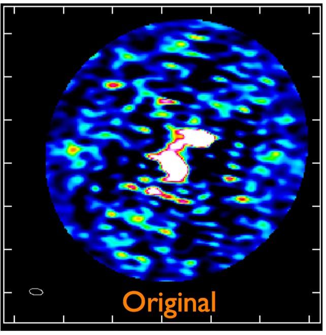

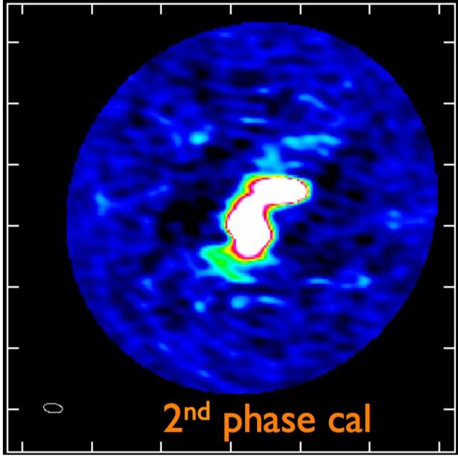
34 S ELF-CALIBRATION USING CLEAN ALMA SV Data for IRAS16293 Band 6 34
35 PRIMARY BEAM CORRECTION Correction is required for the antenna response This is called primary beam correction (as opposed to the synthesized beam / psf ) For dishes, the primary beam is ~constant but can be very complex away from the FWHM. To correct for: multiply final image with the inverse beam! Scalar for total brightness, matrix for polarized

36 PRIMARY BEAM CORRECTION Complex sidelobe structure + asymmetries! Knockin primary beam holographic scan

37 PRIMARY BEAM CORRECTION Primary beam corrected JVLA+MERLIN image of GOODS-N Note the increased noise level towards the edge of the field


38 VA R I A B L E P R I M A RY B E A M S Primary beam of arrays can vary with time and frequency! Has to be accounted for during imaging if imaging the whole primary beam: A-projection (CASA has this for the JVLA + ALMA - VLBI arrays don t image the pb often!)

39 VARIABLE PRIMARY BEAM ary beam frequency variation for the UK Lovell Telescope G Image credit: Nick Wrigley 39
40 MOS AICING t if this is our primary beam and we want to see the FR-I galaxy to 40
41 MOS AICING can use multiple pointings and combine them with correct weightin 41
42 MOS AICING To create the mosaiced image Need to weight with 1/ = (primary beam)2 or Done in CASA with imagermode = 'mosaic'

 Affects position, brightness & polarisation angles!")
43 D I R E C T I O N D E P E N D E N T C A L I B RAT I O N Direction dependent (DD) effects may need further corrections after imaging not a fully solved problem! Can be ionosphere, tropospheric, instrumental (e.g. a projection) Affects position, brightness & polarisation angles! Before DD cal After DD cal 43 Yattawata SAGECal (2007)
 Pre-MSSC 44 Radcliffe et al.")
44 D I R E C T I O N D E P E N D E N T C A L I B RAT I O N Possible solutions: Image in small facets where DD's effects are constant Peeling For VLBI, Multi-source self-calibration (below) Pre-MSSC 44 Radcliffe et al Post-MSSC
45 SUMMARY Topics discussed: CLEAN When to use Multi-scale or other deconvolution methods The effect of and solution to w-terms Multi-frequency deconvolution Self-calibration using CLEAN components Primary beam correction Mosaicing Direction-dependent effects during imaging 45
Imaging and Deconvolution
 Imaging and Deconvolution Urvashi Rau National Radio Astronomy Observatory, Socorro, NM, USA The van-cittert Zernike theorem Ei E V ij u, v = I l, m e sky j 2 i ul vm dldm 2D Fourier transform : Image
Synthesis Imaging. Claire Chandler, Sanjay Bhatnagar NRAO/Socorro
 Synthesis Imaging Claire Chandler, Sanjay Bhatnagar NRAO/Socorro Michelson Summer Workshop Caltech, July 24-28, 2006 Synthesis Imaging 2 Based on the van Cittert-Zernike theorem: The complex visibility
Sky-domain algorithms to reconstruct spatial, spectral and time-variable structure of the sky-brightness distribution
 Sky-domain algorithms to reconstruct spatial, spectral and time-variable structure of the sky-brightness distribution Urvashi Rau National Radio Astronomy Observatory Socorro, NM, USA Outline : - Overview
Imaging and non-imaging analysis
 1 Imaging and non-imaging analysis Greg Taylor University of New Mexico Spring 2017 Plan for the lecture-i 2 How do we go from the measurement of the coherence function (the Visibilities) to the images
Imaging and Deconvolution
 Imaging and Deconvolution 24-28 Sept 202 Narrabri, NSW, Australia Outline : - Synthesis Imaging Concepts - Imaging in Practice Urvashi Rau - Image-Reconstruction Algorithms National Radio Astronomy Observatory
Image Pixelization and Dynamic Range
 EVLA Memo 114 Image Pixelization and Dynamic Range W. D. Cotton, Juan M. Uson NRAO 1 Abstract This study investigates some of the effects of representing the sky by a rectangular grid of pixels on the
Lecture 17 Reprise: dirty beam, dirty image. Sensitivity Wide-band imaging Weighting
 Lecture 17 Reprise: dirty beam, dirty image. Sensitivity Wide-band imaging Weighting Uniform vs Natural Tapering De Villiers weighting Briggs-like schemes Reprise: dirty beam, dirty image. Fourier inversion
How accurately do our imaging algorithms reconstruct intensities and spectral indices of weak sources?
 How accurately do our imaging algorithms reconstruct intensities and spectral indices of weak sources? Urvashi Rau, Sanjay Bhatnagar, Frazer Owen ( NRAO ) 29th Annual New Mexico Symposium, NRAO, Socorro,
ERROR RECOGNITION and IMAGE ANALYSIS
 PREAMBLE TO ERROR RECOGNITION and IMAGE ANALYSIS 2 Why are these two topics in the same lecture? ERROR RECOGNITION and IMAGE ANALYSIS Ed Fomalont Error recognition is used to determine defects in the data
Radio Interferometry Bill Cotton, NRAO. Basic radio interferometry Emphasis on VLBI Imaging application
 Radio Interferometry Bill Cotton, NRAO Basic radio interferometry Emphasis on VLBI Imaging application 2 Simplest Radio Interferometer Monochromatic, point source 3 Interferometer response Adding quarter
High dynamic range imaging, computing & I/O load
 High dynamic range imaging, computing & I/O load RMS ~15µJy/beam RMS ~1µJy/beam S. Bhatnagar NRAO, Socorro Parameterized Measurement Equation Generalized Measurement Equation Obs [ S M V ij = J ij, t W
Wideband Mosaic Imaging for VLASS
 Wideband Mosaic Imaging for VLASS Preliminary ARDG Test Report U.Rau & S.Bhatnagar 29 Aug 2018 (1) Code Validation and Usage (2) Noise, Weights, Continuum sensitivity (3) Imaging parameters (4) Understanding
Synthesis imaging using CASA
 Synthesis imaging using CASA Kuo-Song Wang ( 國松) and ARC-Taiwan team (ASIAA) UCAT Summer Student Program 2016 2016/06/30 Recap Radio interferometric observations The products from the array are Visibilities
The Techniques of Radio Interferometry III: Imaging
 Master Astronomy and Astrophysics - 5214RAAS6Y Radio Astronomy Lecture 8 The Techniques of Radio Interferometry III: Imaging Lecturer: Michael Wise (wise@astron.nl) April 25th, 2013 Westerbork/LOFAR Field
ALMA Memo 386 ALMA+ACA Simulation Tool J. Pety, F. Gueth, S. Guilloteau IRAM, Institut de Radio Astronomie Millimétrique 300 rue de la Piscine, F-3840
 ALMA Memo 386 ALMA+ACA Simulation Tool J. Pety, F. Gueth, S. Guilloteau IRAM, Institut de Radio Astronomie Millimétrique 300 rue de la Piscine, F-38406 Saint Martin d'h eres August 13, 2001 Abstract This
High Dynamic Range Imaging
 High Dynamic Range Imaging Josh Marvil CASS Radio Astronomy School 3 October 2014 CSIRO ASTRONOMY & SPACE SCIENCE High Dynamic Range Imaging Introduction Review of Clean Self- Calibration Direction Dependence
Imaging and Deconvolution
 Imaging and Deconvolution Rick Perley, NRAO/Socorro ATNF Radio School Narrabri, NSW 29 Sept 03 Oct 2014 #G Topics Imaging Formal Solution Discrete Data The Direct Transform The Fast Fourier Transform Weighting,
OSKAR-2: Simulating data from the SKA
 OSKAR-2: Simulating data from the SKA AACal 2012, Amsterdam, 13 th July 2012 Fred Dulwich, Ben Mort, Stef Salvini 1 Overview OSKAR-2: Interferometer and beamforming simulator package. Intended for simulations
Imaging and Deconvolution
 Imaging and Deconvolution David J. Wilner (Harvard-Smithsonian Center for Astrophysics) Fifteenth Synthesis Imaging Workshop 1-8 June 2016 Overview gain some intuition about interferometric imaging understand
Basic Imaging and Self- Calibration (T4 + T7)
") Basic Imaging and Self- Calibration (T4 + T7) John McKean Visibilities Fourier Transform Deconvolution AIM: 1. To make an image by taking the fast Fourier transform of the visibility data. 2. Carry out
Basic Imaging and Self- Calibration (T4 + T7) John McKean Visibilities Fourier Transform Deconvolution AIM: 1. To make an image by taking the fast Fourier transform of the visibility data. 2. Carry out
OSKAR: Simulating data from the SKA
 OSKAR: Simulating data from the SKA Oxford e-research Centre, 4 June 2014 Fred Dulwich, Ben Mort, Stef Salvini 1 Overview Simulating interferometer data for SKA: Radio interferometry basics. Measurement
Correlator Field-of-View Shaping
 Correlator Field-of-View Shaping Colin Lonsdale Shep Doeleman Vincent Fish Divya Oberoi Lynn Matthews Roger Cappallo Dillon Foight MIT Haystack Observatory Context SKA specifications extremely challenging
Wide-Field Imaging I: Non-Coplanar Visibilities
 Wide-Field Imaging I: Non-Coplanar Visibilities Rick Perley Eleventh Synthesis Imaging Workshop Socorro, June 10-17, 2008 Review: Measurement Equation From the first lecture, we have a general relation
Lessons learnt from implementing mosaicing and faceting in ASKAPsoft. Max Voronkov & Tim Cornwell ASKAP team 2nd April 2009
 Lessons learnt from implementing mosaicing and faceting in ASKAPsoft Max Voronkov & Tim Cornwell ASKAP team 2nd April 2009 Outline - Imaging software ASKAPsoft re-uses LOFAR design Imaging is treated as
Continuum error recognition and error analysis
 Continuum error recognition and error analysis Robert Laing (ESO) 1 Outline Error recognition: how do you recognise and diagnose residual errors by looking at images? Image analysis: how do you extract
arxiv: v1 [astro-ph.im] 21 Jun 2017
![arxiv: v1 [astro-ph.im] 21 Jun 2017](/thumbs/92/110097439.jpg "arxiv: v1 [astro-ph.im] 21 Jun 2017") MNRAS, 1 16 (216) Preprint 22 July 218 Compiled using MNRAS LATEX style file v3. An optimized algorithm for multi-scale wideband deconvolution of radio astronomical images A. R. Offringa 1, O. Smirnov
MNRAS, 1 16 (216) Preprint 22 July 218 Compiled using MNRAS LATEX style file v3. An optimized algorithm for multi-scale wideband deconvolution of radio astronomical images A. R. Offringa 1, O. Smirnov
Primary Beams & Radio Interferometric Imaging Performance. O. Smirnov (Rhodes University & SKA South Africa)
") Primary Beams & Radio Interferometric Imaging Performance O. Smirnov (Rhodes University & SKA South Africa) Introduction SKA Dish CoDR (2011), as summarized by Tony Willis: My sidelobes are better than
Primary Beams & Radio Interferometric Imaging Performance O. Smirnov (Rhodes University & SKA South Africa) Introduction SKA Dish CoDR (2011), as summarized by Tony Willis: My sidelobes are better than
Radio interferometric imaging of spatial structure that varies with time and frequency
 Radio interferometric imaging of spatial structure that varies with time and frequency Urvashi Rau National Radio Astronomy Observatory, 1003 Lopezville Road, Socorro, NM-87801, USA ABSTRACT The spatial-frequency
Data Analysis. I have got some data, so what now? Naomi McClure-Griffiths CSIRO Australia Telescope National Facility 2 Oct 2008
 Data Analysis I have got some data, so what now? Naomi McClure-Griffiths CSIRO Australia Telescope National Facility 2 Oct 2008 1 Outline Non-imaging analysis Parameter estimation Point source fluxes,
Controlling Field-of-View of Radio Arrays using Weighting Functions
 Controlling Field-of-View of Radio Arrays using Weighting Functions MIT Haystack FOV Group: Lynn D. Matthews,Colin Lonsdale, Roger Cappallo, Sheperd Doeleman, Divya Oberoi, Vincent Fish Fulfilling scientific
ERROR RECOGNITION & IMAGE ANALYSIS. Gustaaf van Moorsel (NRAO) Ed Fomalont (NRAO) Twelfth Synthesis Imaging Workshop 2010 June 8-15
 Ed Fomalont (NRAO) Twelfth Synthesis Imaging Workshop 2010 June 8-15") ERROR RECOGNITION & IMAGE ANALYSIS Gustaaf van Moorsel (NRAO) Ed Fomalont (NRAO) Twelfth Synthesis Imaging Workshop 2010 June 8-15 INTRODUCTION Why are these two topics Error Recognition and Image Analysis
ERROR RECOGNITION & IMAGE ANALYSIS Gustaaf van Moorsel (NRAO) Ed Fomalont (NRAO) Twelfth Synthesis Imaging Workshop 2010 June 8-15 INTRODUCTION Why are these two topics Error Recognition and Image Analysis
Deconvolution and Imaging ASTR 240: In-class activity, April 1, 2013
 Deconvolution and Imaging ASTR 240: In-class activity, April 1, 2013 In this activity, we will use calibrated visibilities from the Submillimeter Array to create an image of a disk around a nearby young
Antenna Configurations for the MMA
 MMA Project Book, Chapter 15: Array Configuration Antenna Configurations for the MMA Tamara T. Helfer & M.A. Holdaway Last changed 11/11/98 Revision History: 11/11/98: Added summary and milestone tables.
Fast Holographic Deconvolution
 Precision image-domain deconvolution for radio astronomy Ian Sullivan University of Washington 4/19/2013 Precision imaging Modern imaging algorithms grid visibility data using sophisticated beam models
Computational issues for HI
 Computational issues for HI Tim Cornwell, Square Kilometre Array How SKA processes data Science Data Processing system is part of the telescope Only one system per telescope Data flow so large that dedicated
CASA. Algorithms R&D. S. Bhatnagar. NRAO, Socorro
 Algorithms R&D S. Bhatnagar NRAO, Socorro Outline Broad areas of work 1. Processing for wide-field wide-band imaging Full-beam, Mosaic, wide-band, full-polarization Wide-band continuum and spectral-line
A Modified Algorithm for CLEANing Wide-Field Maps with Extended Structures
 J. Astrophys. Astr. (1990) 11, 311 322 A Modified Algorithm for CLEANing Wide-Field Maps with Extended Structures Κ. S. Dwarakanath, A. A. Deshpande & Ν. Udaya Shankar Raman Research institute, Bangalore
IRAM Memo MAPPING for NOEMA: Concepts and Usage
 Original version at http://iram-institute.org/medias/uploads/mapping-noema.pdf IRAM Memo 2016-1 MAPPING for NOEMA: Concepts and Usage S. Guilloteau 1 1. LAB (Bordeaux) 14-Jul-2016 version 1.0 09-Sep-2016
Visualization & the CASA Viewer
 Visualization & the Viewer Juergen Ott & the team Atacama Large Millimeter/submillimeter Array Expanded Very Large Array Robert C. Byrd Green Bank Telescope Very Long Baseline Array Visualization Goals:
Using CASA to Simulate Interferometer Observations
 Using CASA to Simulate Interferometer Observations Nuria Marcelino North American ALMA Science Center Atacama Large Millimeter/submillimeter Array Expanded Very Large Array Robert C. Byrd Green Bank Telescope
Mosaicing and Single-Dish Combination
 Mosaicing and Single-Dish Combination CASS Radio Astronomy School 2012 Lister Staveley-Smith (ICRAR / CAASTRO / UWA) Outline Mosaicing with interferometers! Nyquist sampling! Image formation Combining
Wide-field Wide-band Full-Mueller Imaging
 Wide-field Wide-band Full-Mueller Imaging CALIM2016, Oct. 10th 2016, Socorro, NM S. Bhatnagar NRAO, Socorro The Scientific Motivation Most projects with current telescopes require precise reconstruction
EVLA Memo #132 Report on the findings of the CASA Terabyte Initiative: Single-node tests
 EVLA Memo #132 Report on the findings of the CASA Terabyte Initiative: Single-node tests S. Bhatnagar NRAO, Socorro May 18, 2009 Abstract This note reports on the findings of the Terabyte-Initiative of
Modeling Antenna Beams
 Modeling Antenna Beams Walter Brisken National Radio Astronomy Observatory 2011 Sept 22 1 / 24 What to learn from this talk EM simulations of antennas can be complicated Many people have spent careers
Empirical Parameterization of the Antenna Aperture Illumination Pattern
 Empirical Parameterization of the Antenna Aperture Illumination Pattern Preshanth Jagannathan UCT/NRAO Collaborators : Sanjay Bhatnagar, Walter Brisken Measurement Equation The measurement equation in
NRAO VLA Archive Survey
 NRAO VLA Archive Survey Jared H. Crossley, Loránt O. Sjouwerman, Edward B. Fomalont, and Nicole M. Radziwill National Radio Astronomy Observatory, 520 Edgemont Road, Charlottesville, Virginia, USA ABSTRACT
From multiple images to catalogs
 Lecture 14 From multiple images to catalogs Image reconstruction Optimal co-addition Sampling-reconstruction-resampling Resolving faint galaxies Automated object detection Photometric catalogs Deep CCD
Using CASA to Simulate Interferometer Observations
 Using CASA to Simulate Interferometer Observations Nuria Marcelino North American ALMA Science Center Atacama Large Millimeter/submillimeter Array Expanded Very Large Array Robert C. Byrd Green Bank Telescope
Image Analysis. Jim Lovell
 Image Analysis Jim Lovell ATNF Synthesis Imaging Workshop May 2003 What Do You Want to Measure? (What you want to do and how to do it.)! Flux density of components! Absolute positions! Relative positions
Imaging Strategies and Postprocessing Computing Costs for Large-N SKA Designs
 Imaging Strategies and Postprocessing Computing Costs for Large-N SKA Designs Colin J. Lonsdale Sheperd S Doeleman Divya Oberoi MIT Haystack Observatory 17 July 2004 Abstract: The performance goals of
IRAM mm-interferometry School UV Plane Analysis. IRAM Grenoble
 IRAM mm-interferometry School 2004 1 UV Plane Analysis Frédéric Gueth IRAM Grenoble UV Plane analysis 2 UV Plane analysis The data are now calibrated as best as we can Caution: data are calibrated, but
Adaptive selfcalibration for Allen Telescope Array imaging
 Adaptive selfcalibration for Allen Telescope Array imaging Garrett Keating, William C. Barott & Melvyn Wright Radio Astronomy laboratory, University of California, Berkeley, CA, 94720 ABSTRACT Planned
Multi-Scale CLEAN deconvolution of radio synthesis images
 MULTI-SCALE CLEAN 1 Multi-Scale CLEAN deconvolution of radio synthesis images T.J. Cornwell arxiv:0806.2228v1 [astro-ph] 13 Jun 2008 Abstract Radio synthesis imaging is dependent upon deconvolution algorithms
Self-calibration: about the implementation in GILDAS. Vincent Piétu IRAM. IRAM millimeter interferometry summerschool
 Self-calibration: about the implementation in GILDAS Vincent Piétu IRAM 1 About an interferometer sensitivity One usually considers only the noise equation to assess the feasibility of an observation.
Digital Image Processing. Image Enhancement in the Frequency Domain
 Digital Image Processing Image Enhancement in the Frequency Domain Topics Frequency Domain Enhancements Fourier Transform Convolution High Pass Filtering in Frequency Domain Low Pass Filtering in Frequency
ASKAP Pipeline processing and simulations. Dr Matthew Whiting ASKAP Computing, CSIRO May 5th, 2010
 ASKAP Pipeline processing and simulations Dr Matthew Whiting ASKAP Computing, CSIRO May 5th, 2010 ASKAP Computing Team Members Team members Marsfield: Tim Cornwell, Ben Humphreys, Juan Carlos Guzman, Malte
Computer Vision I. Announcements. Fourier Tansform. Efficient Implementation. Edge and Corner Detection. CSE252A Lecture 13.
 Announcements Edge and Corner Detection HW3 assigned CSE252A Lecture 13 Efficient Implementation Both, the Box filter and the Gaussian filter are separable: First convolve each row of input image I with
Lecture 8 Object Descriptors
 Lecture 8 Object Descriptors Azadeh Fakhrzadeh Centre for Image Analysis Swedish University of Agricultural Sciences Uppsala University 2 Reading instructions Chapter 11.1 11.4 in G-W Azadeh Fakhrzadeh
S.A. Torchinsky, A. van Ardenne, T. van den Brink-Havinga, A.J.J. van Es, A.J. Faulkner (eds.) 4-6 November 2009, Château de Limelette, Belgium
 4-6 November 2009, Château de Limelette, Belgium") WIDEFIELD SCIENCE AND TECHNOLOGY FOR THE SKA SKADS CONFERENCE 2009 S.A. Torchinsky, A. van Ardenne, T. van den Brink-Havinga, A.J.J. van Es, A.J. Faulkner (eds.) 4-6 November 2009, Château de Limelette,
WIDEFIELD SCIENCE AND TECHNOLOGY FOR THE SKA SKADS CONFERENCE 2009 S.A. Torchinsky, A. van Ardenne, T. van den Brink-Havinga, A.J.J. van Es, A.J. Faulkner (eds.) 4-6 November 2009, Château de Limelette,
GEOG 4110/5100 Advanced Remote Sensing Lecture 2
 GEOG 4110/5100 Advanced Remote Sensing Lecture 2 Data Quality Radiometric Distortion Radiometric Error Correction Relevant reading: Richards, sections 2.1 2.8; 2.10.1 2.10.3 Data Quality/Resolution Spatial
ALMA Memo No An Imaging Study for ACA. Min S. Yun. University of Massachusetts. April 1, Abstract
 ALMA Memo No. 368 An Imaging Study for ACA Min S. Yun University of Massachusetts April 1, 2001 Abstract 1 Introduction The ALMA Complementary Array (ACA) is one of the several new capabilities for ALMA
van Cittert-Zernike Theorem
 van Cittert-Zernike Theorem Fundamentals of Radio Interferometry, Section 4.5 Griffin Foster SKA SA/Rhodes University NASSP 2016 What is the Fourier transform of the sky? NASSP 2016 2:21 Important Points:
A Correlation Test: What were the interferometric observation conditions?
 A Correlation Test: What were the interferometric observation conditions? Correlation in Practical Systems For Single-Pass Two-Aperture Interferometer Systems System noise and baseline/volumetric decorrelation
EVLA memo 77. EVLA and SKA computing costs for wide field imaging. (Revised) 1. T.J. Cornwell, NRAO 2
 1. T.J. Cornwell, NRAO 2") EVLA memo 77 EVLA and SKA computing costs for wide field imaging (Revised) 1 T.J. Cornwell, NRAO 2 tcornwel@nrao.edu Abstract: I investigate the problem of high dynamic range continuum imaging in the presence
EVLA memo 77 EVLA and SKA computing costs for wide field imaging (Revised) 1 T.J. Cornwell, NRAO 2 tcornwel@nrao.edu Abstract: I investigate the problem of high dynamic range continuum imaging in the presence
Wide field polarization calibration in the image plane using the Allen Telescope Array
 Wide field polarization calibration in the image plane using the Allen Telescope Array Mattieu de Villiers, SKA SA Casey Law, UC Berkeley 8 October 00 Abstract This study investigates wide field polarization
Image Processing and Analysis
 Image Processing and Analysis 3 stages: Image Restoration - correcting errors and distortion. Warping and correcting systematic distortion related to viewing geometry Correcting "drop outs", striping and
Overview. Spectral Processing of Point- Sampled Geometry. Introduction. Introduction. Fourier Transform. Fourier Transform
 Overview Spectral Processing of Point- Sampled Geometry Introduction Fourier transform Spectral processing pipeline Spectral filtering Adaptive subsampling Summary Point-Based Computer Graphics Markus
Radio astronomy data reduction at the Institute of Radio Astronomy
 Mem. S.A.It. Suppl. Vol. 13, 79 c SAIt 2009 Memorie della Supplementi Radio astronomy data reduction at the Institute of Radio Astronomy J.S. Morgan INAF Istituto di Radioastronomia, Via P. Gobetti, 101
Digital Image Processing. Lecture 6
 Digital Image Processing Lecture 6 (Enhancement in the Frequency domain) Bu-Ali Sina University Computer Engineering Dep. Fall 2016 Image Enhancement In The Frequency Domain Outline Jean Baptiste Joseph
SSW, Radio, X-ray, and data analysis
 SSW, Radio, X-ray, and data analysis Eduard Kontar School of Physics and Astronomy University of Glasgow, UK CESRA Summer School, Glasgow, August 2015 SSW Pre-school installation guide for IDL, SSW and
Computer Vision. Fourier Transform. 20 January Copyright by NHL Hogeschool and Van de Loosdrecht Machine Vision BV All rights reserved
 Van de Loosdrecht Machine Vision Computer Vision Fourier Transform 20 January 2017 Copyright 2001 2017 by NHL Hogeschool and Van de Loosdrecht Machine Vision BV All rights reserved j.van.de.loosdrecht@nhl.nl,
ALMA simulations Rosita Paladino. & the Italian ARC
 ALMA simulations Rosita Paladino & the Italian ARC Two software tools available to help users simulate images resulting from an ALMA observations: Simulations with CASA tasks sim_observe & sim_analyze
Chapter 9. Coherence
 Chapter 9. Coherence Last Lecture Michelson Interferometer Variations of the Michelson Interferometer Fabry-Perot interferometer This Lecture Fourier analysis Temporal coherence and line width Partial
Single-epoch Measurement Algorithms Robert Lupton Applications Lead
 Single-epoch Measurement Algorithms Robert Lupton Applications Lead 2013-09-19 CDP FINAL DESIGN REVIEW September 19-20, 2013 Name of Mee)ng Loca)on Date - Change in Slide Master 1 Outline Single-epoch
Computer Vision and Graphics (ee2031) Digital Image Processing I
 Digital Image Processing I") Computer Vision and Graphics (ee203) Digital Image Processing I Dr John Collomosse J.Collomosse@surrey.ac.uk Centre for Vision, Speech and Signal Processing University of Surrey Learning Outcomes After
Computer Vision and Graphics (ee203) Digital Image Processing I Dr John Collomosse J.Collomosse@surrey.ac.uk Centre for Vision, Speech and Signal Processing University of Surrey Learning Outcomes After
Pre-Processing and Calibration for Million Source Shallow Survey
 Pre-Processing and Calibration for Million Source Shallow Survey V.N. Pandey(Kapteyn Institute/ASTRON) for LOFAR Offline Processing Team April 1 st, 2009 CALIM 09, Socorro Outline 1 2 3 4 MSSS (MS 3 )
Digital Image Processing. Prof. P. K. Biswas. Department of Electronic & Electrical Communication Engineering
 Digital Image Processing Prof. P. K. Biswas Department of Electronic & Electrical Communication Engineering Indian Institute of Technology, Kharagpur Lecture - 21 Image Enhancement Frequency Domain Processing
Introduction to Sampled Signals and Fourier Transforms
 Introduction to Sampled Signals and Fourier Transforms Physics116C, 4/28/06 D. Pellett References: Essick, Advanced LabVIEW Labs Press et al., Numerical Recipes, Ch. 12 Brigham, The Fast Fourier Transform
Central Slice Theorem
 Central Slice Theorem Incident X-rays y f(x,y) R x r x Detected p(, x ) The thick line is described by xcos +ysin =R Properties of Fourier Transform F [ f ( x a)] F [ f ( x)] e j 2 a Spatial Domain Spatial
ALMA Antenna responses in CASA imaging
 ALMA Antenna responses in CASA imaging Dirk Petry (ESO), December 2012 Outline Motivation ALBiUS/ESO work on CASA responses infrastructure and ALMA beam library First test results 1 Motivation ALMA covers
Imaging and Image Analysis
 Imaging and Image Analysis Urvashi R.V. National Radio Astronomy Observatory, Socorro, NM, USA 6th VLA Data Reduction Workshop ( 23 27 October, 2017 ) Outline - Synthesis imaging as implemented in CASA
MAPPING. March 29th, Version 2.0. Questions? Comments? Bug reports? Mail to:
 i MAPPING A gildas software March 29th, 2007 Version 2.0 Questions? Comments? Bug reports? Mail to: gildas@iram.fr The gildas team welcomes an acknowledgment in publications using gildas software to reduce
Imaging Supermassive Black Holes with the Event Horizon Telescope
 Counter Jet Model Forward Jet Kazunori Akiyama, NEROC Symposium: Radio Science and Related Topics, MIT Haystack Observatory, 11/04/2016 Imaging Supermassive Black Holes with the Event Horizon Telescope
The Virtual Observatory in Australia Connecting to International Initiatives. Peter Lamb. CSIRO Mathematical & Information Sciences
 The Virtual Observatory in Australia Connecting to International Initiatives Peter Lamb CSIRO Mathematical & Information Sciences The Grid & escience Convergence of high-performance computing, huge data
Digital Image Processing
 Digital Image Processing Third Edition Rafael C. Gonzalez University of Tennessee Richard E. Woods MedData Interactive PEARSON Prentice Hall Pearson Education International Contents Preface xv Acknowledgments
Video Mosaics for Virtual Environments, R. Szeliski. Review by: Christopher Rasmussen
 Video Mosaics for Virtual Environments, R. Szeliski Review by: Christopher Rasmussen September 19, 2002 Announcements Homework due by midnight Next homework will be assigned Tuesday, due following Tuesday.
Do It Yourself 8. Polarization Coherence Tomography (P.C.T) Training Course
 Training Course") Do It Yourself 8 Polarization Coherence Tomography (P.C.T) Training Course 1 Objectives To provide a self taught introduction to Polarization Coherence Tomography (PCT) processing techniques to enable
Do It Yourself 8 Polarization Coherence Tomography (P.C.T) Training Course 1 Objectives To provide a self taught introduction to Polarization Coherence Tomography (PCT) processing techniques to enable
GBT Memo #300: Correcting ALMA 12-m Array Data for Missing Short Spacings Using the Green Bank Telescope
 GBT Memo #300: Correcting ALMA 12-m Array Data for Missing Short Spacings Using the Green Bank Telescope Melissa Hoffman and Amanda Kepley 28 September 2018 Contents 1 Introduction 1 2 Data 2 2.1 Observations
Image Processing. Filtering. Slide 1
 Image Processing Filtering Slide 1 Preliminary Image generation Original Noise Image restoration Result Slide 2 Preliminary Classic application: denoising However: Denoising is much more than a simple
OSKAR Settings Files Revision: 8
 OSKAR Settings Files Version history: Revision Date Modification 1 212-4-23 Creation. 2 212-5-8 Added default value column to settings tables. 3 212-6-13 Updated settings for version 2..2-beta. 4 212-7-27
Scaled representations
 Scaled representations Big bars (resp. spots, hands, etc.) and little bars are both interesting Stripes and hairs, say Inefficient to detect big bars with big filters And there is superfluous detail in
Edge detection. Convert a 2D image into a set of curves. Extracts salient features of the scene More compact than pixels
 Edge Detection Edge detection Convert a 2D image into a set of curves Extracts salient features of the scene More compact than pixels Origin of Edges surface normal discontinuity depth discontinuity surface
Development of Focal-Plane Arrays and Beamforming Networks at DRAO
 Development of Focal-Plane Arrays and Beamforming Networks at DRAO Bruce Veidt Dominion Radio Astrophysical Observatory Herzberg Institute of Astrophysics National Research Council of Canada Penticton,
Fundamentals of Digital Image Processing
 \L\.6 Gw.i Fundamentals of Digital Image Processing A Practical Approach with Examples in Matlab Chris Solomon School of Physical Sciences, University of Kent, Canterbury, UK Toby Breckon School of Engineering,
EXAM SOLUTIONS. Image Processing and Computer Vision Course 2D1421 Monday, 13 th of March 2006,
 School of Computer Science and Communication, KTH Danica Kragic EXAM SOLUTIONS Image Processing and Computer Vision Course 2D1421 Monday, 13 th of March 2006, 14.00 19.00 Grade table 0-25 U 26-35 3 36-45
Tracking Computer Vision Spring 2018, Lecture 24
 Tracking http://www.cs.cmu.edu/~16385/ 16-385 Computer Vision Spring 2018, Lecture 24 Course announcements Homework 6 has been posted and is due on April 20 th. - Any questions about the homework? - How
What might astronomers want? Flexible data products and remotely-steered pipelines
 What might astronomers want? Flexible data products and remotely-steered pipelines Anita Richards AstroGrid / ALMA Regional Centre JBCA, University of Manchester thanks to e-merlin, ALMA, RadioNet ALBiUS
ANALYSIS OF GEOPHYSICAL POTENTIAL FIELDS A Digital Signal Processing Approach
 ADVANCES IN EXPLORATION GEOPHYSICS 5 ANALYSIS OF GEOPHYSICAL POTENTIAL FIELDS A Digital Signal Processing Approach PRABHAKAR S. NAIDU Indian Institute of Science, Bangalore 560012, India AND M.P. MATHEW
Multimedia Computing: Algorithms, Systems, and Applications: Edge Detection
 Multimedia Computing: Algorithms, Systems, and Applications: Edge Detection By Dr. Yu Cao Department of Computer Science The University of Massachusetts Lowell Lowell, MA 01854, USA Part of the slides
Introduction to Computer Vision. Week 8, Fall 2010 Instructor: Prof. Ko Nishino
 Introduction to Computer Vision Week 8, Fall 2010 Instructor: Prof. Ko Nishino Midterm Project 2 without radial distortion correction with radial distortion correction Light Light Light! How do you recover