Introduction to the Finite Element Method (3)
|
|
|
- Rosaline Lloyd
- 6 years ago
- Views:
Transcription
1 Introduction to the Finite Element Method (3) Petr Kabele Czech Technical University in Prague Faculty of Civil Engineering Czech Republic people.fsv.cvut.cz/~pkabele 1
2 Outline Types of finite element programs Practical aspects of finite element analysis Examples of FE modeling 2
3 Finite element programs classification and structure FEM programs general purpose simulation of general physical problems (statics, dynamics, heat/mass transport, magnetism,..., coupled problems) more complex problem definition/input (choice from many options) user must perfectly understand the mathematical and physical essence of analyzed problem e.g DIANA, ADINA, ABAQUS specialized, engineering simulation of specific engineering problems (e.g. elastic truss structure) user-friendly input (mouse-click, predefined material models, structural members, cross-sections etc., close linkage to design codes) use in engineering practice (structural design) e.g. SAP 3


4 Structure of finite element programs Preprocesor graphical interface for data input Computational core FE program itself Postprocesor graphical interface for processing and visualization of results 4


5 Practical aspects of finite element analysis General consideration: Finite element analysis is essentially an approximate method for calculating the behavior of real structures by performing an algebraic solution of a set of equations describing idealized structures Physical reality Finite element model 5
6 Selection of analysis type Consider what physical phenomena should be analyzed. mechanical static dynamic stress analysis stability linear nonlinear heat transport mass transport fluid magnetism modal analysis transient analysis linear nonlinear coupled, interaction
7 Selection of modeling hypotheses The most difficult part Geometry and morphology (model scope and detail, structural form, internal composition, connections between the structural elements, ) Material models and properties Actions (mechanical, physical, chemical ) Existing alterations and damage (cracks, constructional mistakes, disconnections, crushing, leanings, ) The interaction of the structure with its surroundings (soil, fluids, other structural parts,...) 7
8 To this end: Clarify what result is anticipated (e.g. overall deformation of a large structure vs. crack propagation at a detail). Consider, what information about the analyzed structure is available (geometry, material, surroundings/supports, loading). Think of suitable simplification, reduction of dimension, substructuring, decomposition, use of symmetry. Select suitable kinematic assumptions and dimension (truss, beam, 2- D solid, plate, shell, 3-D solid). Bear in mind the complexity of model, solution time, postprocessing time and visualization of results. In complex problems, combining various kinematic assumptions may be efficient (e.g. beam + plate). However, proper linkage of all DOF s must be ensured. 8
9 Pre-analysis Make a rough estimation of the expected result (e.g. simplified calculation by hand). Estimate locations of strain concentration and locations of uniform strain use denser mesh in locations with steeper gradients. Run a pilot analysis with coarser mesh compare results with the rough estimate use the results to identify further locations of strain concentration Refinement and analysis Refine the hypotheses and FE mesh as necessary based on the previous step and run the analysis 9
10 Preliminary results check Always check after analysis plot magnified displacement of the model, display the stresses (generalized stresses), reactions Compare results with the rough estimate. Check that loading and kinematic boundary conditions act as expected (stress under loading must correspond to imposed distributed load, outer reactions must be in equilibrium with imposed loading). Check for possible discontinuities due to improper meshing (overlaps of mesh, unexpected stress concentrations) If check fails, find and correct mistakes in input and return to Refinement and analysis. 10


11 Example: 11
12 Rigorous results check Analysis verification: Is the mathematical formulation solved correctly? Check error/accuracy/convergence messages. Check mesh quality criteria Analysis validation Does the mathematical model correctly represent the physical reality? Validation of modeling hypotheses... see SA2 Lecture 1. 12
13 Results processing and presentation FE analysis usually produces huge amount of data. These must be sorted out and presented in an easy-to-understand way. Some examples: plot of deformed configuration contour plots of field variables (displacement, stress, strain, components or principal values,...) vector plots (displacements, principal stress, strain,...) line plots of field variables along line, section time history plots/tables of values in given points extreme values of field variables (see idiana intro for examples) 13
: E= 30 GPa ν= 0.")
14 Example 1 Perform analysis of a slab. Uniform distributed load 8 kn/m 2 (incl. self weight) Thickness: 0.15 m Plan: 2 x 3 m Material (R/C): E= 30 GPa ν= 0.2 Supports allow free sliding and rotation but no vertical movement (up or down) 14
")
15 Model 1 : plate elements mesh 1 3-node plate elements 6 DOF/node (3 translations + 3 rotations) mesh 2 15
16 Model 1 : plate elements Boundary conditions u, v, ϕ x, ϕ y, ϕ z... free w... fixed ϕ x, ϕ y, ϕ z... free u, v, w... fixed u, v, ϕ x, ϕ y, ϕ z... free w... fixed v, ϕ x, ϕ y, ϕ z... free u, w... fixed u, v, ϕ x, ϕ y, ϕ z... free w... fixed Note: these point BC are imposed to prevent rigid body movement in slab plane. 16


17 Model 1 : plate elements - results Deflection 17
18 Model 1 : plate elements - results Bending moment intensities Mesh 1: Element 59 m x m y Int point E E-03 Int point E E-03 Int point E E-03 Average: E Mesh 2: Element 431 m x m y Int point E E-03 Int point E E-03 Int point E E-03 Average e
19 Model 1 : plate elements - results Stress... may be not directly accessible, calculated from σ = ± 6 y, ext 2 h my σ y,ext = ± MPa σ y,ext = ± MPa 19
")
20 Model 1 : plate elements - results Deformed shape and reactions (notice corner forces) 20
")
21 Model 1 : plate elements - results Deformed shape and reactions (notice corner forces) 21
22 Model 2 : solid elements mesh 1 20-node isoparametric solid elements 3 DOF/node (3 translations) mesh 2 mesh 3 22
23 Model 2 : solid elements Boundary conditions u, v... free w... fixed u, v, w... fixed u, v... free w... fixed z, w u, w... fixed x, u y, v u, v... free w... fixed Note: these point BC are imposed to prevent rigid body movement in slab plane. 23


24 Model 2 : solid elements - results Deflection 24
")
25 Model 2 : solid elements - results Deformed shape and reactions (notice corner forces) 25

26 Model 2 : solid elements - results Bending stress σ y 26
27 Models 1, 2, 3: comparison Deflection y-axis 27
28 Models 1, 2, 3: comparison Model Extreme stress (MPa) Plate 1 ±1.54 Plate 2 ±1.50 Solid 1 ±1.64 *) Solid 2 ±1.57 *) Solid 3 ±1.59 *) *) extrapolated values 28
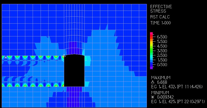
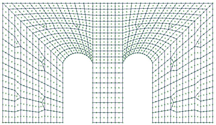
29 Example 2 Perform a stress analysis of a wall exposed to uniform load, self-weight and foundation settlement. Identify the locations and magnitudes of maximum tension. 29
30 Initial calculation 4-node isoparematric quarilateral plane stress elements (Q4) 30
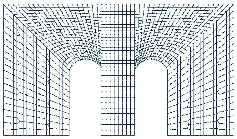
31 Deformed mesh 31

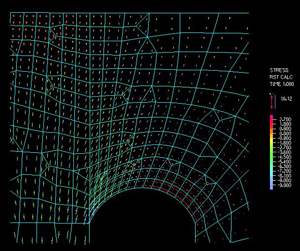
32 Principal stresses 32
33 Maximum principal stress 33
34 Maximum principal stress smoothed plot 34

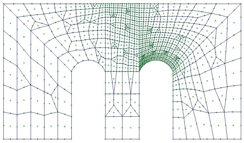
35 Convergence study meshes Q4 elements Q9 elements 35
36 Convergence of extreme displacement Convergence of max. princ. stress E u_ext E E E E E E-03 Q4 Q9 Q9a sig_max Q4 Q9 Q9a E E E DOF DOF Mesh El. type # of elem # of DOF u_ext sig_max 1 Q E Q E Q E Q E Q E Q E r Q E
37 Maximum principal stress Q4 elements Q9 elements 37

38 Maximum principal stress Q4 elements Q9 elements 38
39 Maximum principal stress Q4 elements Q9 elements 39
40 Local refinement 40
41 41
42 Convergence of extreme displacement Convergence of max. princ. stress E u_ext E E E E E E-03 Q4 Q9 Q9a sig_max Q4 Q9 Q9a E E E DOF DOF 42
43 References K.J. Bathe: Finite Element Procedures, Prentice Hall, Inc., 1996 ADINA R&D, Inc.: Theory and modeling guide, Volume I: ADINA, November 2006 TNO DIANA BV.: DIANA User's Manual -- Release Teacher Edition, 2008, 43
44 Remark This document is designated solely as a teaching aid for students of CTU in Prague, Faculty of Civil Engineering, course Numerické metody v inženýrských úlohách. This document is being continuously updated and corrected by the author. Despite author s utmost effort, it may contain inaccuracies and errors. Limitation on Liability. Except to the extent required by applicable law, in no event will the author be liable to any user of this document on any legal theory for any special, incidental, consequential, punitive or exemplary damages arising out of the use of the work, even if author has been advised of the possibility of such damages. This is a copyrighted document Petr Kabele, Last modified:
Finite Element Method. Chapter 7. Practical considerations in FEM modeling
 Finite Element Method Chapter 7 Practical considerations in FEM modeling Finite Element Modeling General Consideration The following are some of the difficult tasks (or decisions) that face the engineer
MAE Advanced Computer Aided Design. 01. Introduction Doc 02. Introduction to the FINITE ELEMENT METHOD
 MAE 656 - Advanced Computer Aided Design 01. Introduction Doc 02 Introduction to the FINITE ELEMENT METHOD The FEM is A TOOL A simulation tool The FEM is A TOOL NOT ONLY STRUCTURAL! Narrowing the problem
course outline basic principles of numerical analysis, intro FEM
 idealization, equilibrium, solutions, interpretation of results types of numerical engineering problems continuous vs discrete systems direct stiffness approach differential & variational formulation introduction
Revised Sheet Metal Simulation, J.E. Akin, Rice University
 Revised Sheet Metal Simulation, J.E. Akin, Rice University A SolidWorks simulation tutorial is just intended to illustrate where to find various icons that you would need in a real engineering analysis.
Scientific Manual FEM-Design 17.0
 Scientific Manual FEM-Design 17. 1.4.6 Calculations considering diaphragms All of the available calculation in FEM-Design can be performed with diaphragms or without diaphragms if the diaphragms were defined
CHAPTER 1. Introduction
 ME 475: Computer-Aided Design of Structures 1-1 CHAPTER 1 Introduction 1.1 Analysis versus Design 1.2 Basic Steps in Analysis 1.3 What is the Finite Element Method? 1.4 Geometrical Representation, Discretization
Finite element method - tutorial no. 1
 Martin NESLÁDEK Faculty of mechanical engineering, CTU in Prague 11th October 2017 1 / 22 Introduction to the tutorials E-mail: martin.nesladek@fs.cvut.cz Room no. 622 (6th floor - Dept. of mechanics,
Introduction to Finite Element Analysis using ANSYS
 Introduction to Finite Element Analysis using ANSYS Sasi Kumar Tippabhotla PhD Candidate Xtreme Photovoltaics (XPV) Lab EPD, SUTD Disclaimer: The material and simulations (using Ansys student version)
COMPUTER AIDED ENGINEERING. Part-1
 COMPUTER AIDED ENGINEERING Course no. 7962 Finite Element Modelling and Simulation Finite Element Modelling and Simulation Part-1 Modeling & Simulation System A system exists and operates in time and space.
ME 475 FEA of a Composite Panel
 ME 475 FEA of a Composite Panel Objectives: To determine the deflection and stress state of a composite panel subjected to asymmetric loading. Introduction: Composite laminates are composed of thin layers
Computational methods - modelling and simulation
 Computational methods - modelling and simulation J. Pamin With thanks to: Authors of presented simulations C.A. Felippa (Univ. of Colorado at Boulder) www.colorado.edu/engineering/cas/courses.d/ifem.d
Chapter 7 Practical Considerations in Modeling. Chapter 7 Practical Considerations in Modeling
 CIVL 7/8117 1/43 Chapter 7 Learning Objectives To present concepts that should be considered when modeling for a situation by the finite element method, such as aspect ratio, symmetry, natural subdivisions,
Chapter 3 Analysis of Original Steel Post
 Chapter 3. Analysis of original steel post 35 Chapter 3 Analysis of Original Steel Post This type of post is a real functioning structure. It is in service throughout the rail network of Spain as part
Revision of the SolidWorks Variable Pressure Simulation Tutorial J.E. Akin, Rice University, Mechanical Engineering. Introduction
 Revision of the SolidWorks Variable Pressure Simulation Tutorial J.E. Akin, Rice University, Mechanical Engineering Introduction A SolidWorks simulation tutorial is just intended to illustrate where to
Computational methods - modelling and simulation
 Computational methods - modelling and simulation J. Pamin Institute for Computational Civil Engineering Civil Engineering Department, Cracow University of Technology URL: www.l5.pk.edu.pl Lecture contents
The Role of Finite Element Analysis in Light Aircraft Design and Certification
 The Role of Finite Element Analysis in Light Aircraft Design and Certification Nigel Bamber Wey Valley Aeronautics Ltd www.weyvalleyaero.co.uk Engineering Consultancy Civil and Military Aerospace and Motorsport
Introduction to Finite Element Method
 Guest Lecture in Prodi Teknik Sipil Introduction to Finite Element Method Wong Foek Tjong, Ph.D. Petra Christian University Surabaya Lecture Outline 1. Overview of the FEM 2. Computational steps of the
Engineering Analysis
 Engineering Analysis with SOLIDWORKS Simulation 2018 Paul M. Kurowski SDC PUBLICATIONS Better Textbooks. Lower Prices. www.sdcpublications.com Powered by TCPDF (www.tcpdf.org) Visit the following websites
CHAPTER 4. Numerical Models. descriptions of the boundary conditions, element types, validation, and the force
 CHAPTER 4 Numerical Models This chapter presents the development of numerical models for sandwich beams/plates subjected to four-point bending and the hydromat test system. Detailed descriptions of the
Guidelines for proper use of Plate elements
 Guidelines for proper use of Plate elements In structural analysis using finite element method, the analysis model is created by dividing the entire structure into finite elements. This procedure is known
TABLE OF CONTENTS WHAT IS ADVANCE DESIGN? INSTALLING ADVANCE DESIGN... 8 System requirements... 8 Advance Design installation...
 Starting Guide 2019 TABLE OF CONTENTS INTRODUCTION... 5 Welcome to Advance Design... 5 About this guide... 6 Where to find information?... 6 Contacting technical support... 6 WHAT IS ADVANCE DESIGN?...
Module 1: Introduction to Finite Element Analysis. Lecture 4: Steps in Finite Element Analysis
 25 Module 1: Introduction to Finite Element Analysis Lecture 4: Steps in Finite Element Analysis 1.4.1 Loading Conditions There are multiple loading conditions which may be applied to a system. The load
Investigation of the behaviour of single span reinforced concrete historic bridges by using the finite element method
 Structural Studies, Repairs and Maintenance of Heritage Architecture XI 279 Investigation of the behaviour of single span reinforced concrete historic bridges by using the finite element method S. B. Yuksel
Engineering Effects of Boundary Conditions (Fixtures and Temperatures) J.E. Akin, Rice University, Mechanical Engineering
 J.E. Akin, Rice University, Mechanical Engineering") Engineering Effects of Boundary Conditions (Fixtures and Temperatures) J.E. Akin, Rice University, Mechanical Engineering Here SolidWorks stress simulation tutorials will be re-visited to show how they
Engineering Effects of Boundary Conditions (Fixtures and Temperatures) J.E. Akin, Rice University, Mechanical Engineering Here SolidWorks stress simulation tutorials will be re-visited to show how they
Learning Module 8 Shape Optimization
 Learning Module 8 Shape Optimization What is a Learning Module? Title Page Guide A Learning Module (LM) is a structured, concise, and self-sufficient learning resource. An LM provides the learner with
About the Author. Acknowledgements
 About the Author Dr. Paul Kurowski obtained his M.Sc. and Ph.D. in Applied Mechanics from Warsaw Technical University. He completed postdoctoral work at Kyoto University. Dr. Kurowski is an Assistant Professor
FOUNDATION IN OVERCONSOLIDATED CLAY
 1 FOUNDATION IN OVERCONSOLIDATED CLAY In this chapter a first application of PLAXIS 3D is considered, namely the settlement of a foundation in clay. This is the first step in becoming familiar with the
SETTLEMENT OF A CIRCULAR FOOTING ON SAND
 1 SETTLEMENT OF A CIRCULAR FOOTING ON SAND In this chapter a first application is considered, namely the settlement of a circular foundation footing on sand. This is the first step in becoming familiar
ANSYS Element. elearning. Peter Barrett October CAE Associates Inc. and ANSYS Inc. All rights reserved.
 ANSYS Element Selection elearning Peter Barrett October 2012 2012 CAE Associates Inc. and ANSYS Inc. All rights reserved. ANSYS Element Selection What is the best element type(s) for my analysis? Best
Reinforced concrete beam under static load: simulation of an experimental test
 Reinforced concrete beam under static load: simulation of an experimental test analys: nonlin physic. constr: suppor. elemen: bar cl12i cl3cm compos cq16m interf pstres reinfo struct. load: deform weight.
Workshop 15. Single Pass Rolling of a Thick Plate
 Introduction Workshop 15 Single Pass Rolling of a Thick Plate Rolling is a basic manufacturing technique used to transform preformed shapes into a form suitable for further processing. The rolling process
Topology Optimization and Analysis of Crane Hook Model
 RESEARCH ARTICLE Topology Optimization and Analysis of Crane Hook Model Thejomurthy M.C 1, D.S Ramakrishn 2 1 Dept. of Mechanical engineering, CIT, Gubbi, 572216, India 2 Dept. of Mechanical engineering,
A Multiple Constraint Approach for Finite Element Analysis of Moment Frames with Radius-cut RBS Connections
 A Multiple Constraint Approach for Finite Element Analysis of Moment Frames with Radius-cut RBS Connections Dawit Hailu +, Adil Zekaria ++, Samuel Kinde +++ ABSTRACT After the 1994 Northridge earthquake
[3] Rigid Body Analysis
![[3] Rigid Body Analysis](/thumbs/92/109073357.jpg "[3] Rigid Body Analysis") [3] Rigid Body Analysis Page 1 of 53 [3] Rigid Body Analysis [3.1] Equilibrium of a Rigid Body [3.2] Equations of Equilibrium [3.3] Equilibrium in 3-D [3.4] Simple Trusses [3.5] The Method of Joints [3.6]
[3] Rigid Body Analysis Page 1 of 53 [3] Rigid Body Analysis [3.1] Equilibrium of a Rigid Body [3.2] Equations of Equilibrium [3.3] Equilibrium in 3-D [3.4] Simple Trusses [3.5] The Method of Joints [3.6]
Settlement of a circular silo foundation
 Engineering manual No. 22 Updated: 02/2018 Settlement of a circular silo foundation Program: FEM File: Demo_manual_22.gmk The objective of this manual is to describe the solution to a circular silo foundation
 Set No. 1 IV B.Tech. I Semester Regular Examinations, November 2010 FINITE ELEMENT METHODS (Mechanical Engineering) Time: 3 Hours Max Marks: 80 Answer any FIVE Questions All Questions carry equal marks
Figure 30. Degrees of freedom of flat shell elements
 Shell finite elements There are three types of shell finite element; 1) flat elements, 2) elements based on the Sanders-Koiter equations and 3) elements based on reduction of a solid element. Flat elements
2008 International ANSYS Conference
 2008 International ANSYS Conference FEM AND FSI SIMULATIONS OF IMPACT LOADS ON GRP SUBSEA COMPOSITE COVERS Kjetil Rognlien, MSc Technical Consultant EDR AS, Norway 2008 ANSYS, Inc. All rights reserved.
Creo Simulate 3.0 Tutorial
 Creo Simulate 3.0 Tutorial Structure and Thermal Roger Toogood, Ph.D., P. Eng. SDC PUBLICATIONS Better Textbooks. Lower Prices. www.sdcpublications.com Powered by TCPDF (www.tcpdf.org) Visit the following
ENGINEERING TRIPOS PART IIA FINITE ELEMENT METHOD
 ENGINEERING TRIPOS PART IIA LOCATION: DPO EXPERIMENT 3D7 FINITE ELEMENT METHOD Those who have performed the 3C7 experiment should bring the write-up along to this laboratory Objectives Show that the accuracy
Introduction to Abaqus. About this Course
 Introduction to Abaqus R 6.12 About this Course Course objectives Upon completion of this course you will be able to: Use Abaqus/CAE to create complete finite element models. Use Abaqus/CAE to submit and
ME Optimization of a Frame
 ME 475 - Optimization of a Frame Analysis Problem Statement: The following problem will be analyzed using Abaqus. 4 7 7 5,000 N 5,000 N 0,000 N 6 6 4 3 5 5 4 4 3 3 Figure. Full frame geometry and loading
FEA Applications I MET 415 Review Course Structure: 15 week course Weekly Schedule 50 minute lecture 2.5 hour laboratory 50 minute lecture
 FEA Applications I MET 415 Review Course Structure: 15 week course Weekly Schedule 50 minute lecture 2.5 hour laboratory 50 minute lecture Goal: Obtain feedback from Industry Users on course presentation
Problem description. The FCBI-C element is used in the fluid part of the model.
 Problem description This tutorial illustrates the use of ADINA for analyzing the fluid-structure interaction (FSI) behavior of a flexible splitter behind a 2D cylinder and the surrounding fluid in a channel.
Introduction to FEM Modeling
 Total Analysis Solution for Multi-disciplinary Optimum Design Apoorv Sharma midas NFX CAE Consultant 1 1. Introduction 2. Element Types 3. Sample Exercise: 1D Modeling 4. Meshing Tools 5. Loads and Boundary
DETECTION AND QUANTIFICATION OF CRACKS IN PRESSURE VESSELS USING ESPI AND FEA MODELLS
 DETECTION AND QUANTIFICATION OF CRACKS IN PRESSURE VESSELS USING ESPI AND FEA MODELLS J GRYZAGORIDIS, DM FINDEIS, JR MYLES Department of Mechanical Engineering University of Cape Town Abstract Non destructive
Settlement Analysis of a Strip Footing Linear Static Analysis (Benchmark Example)
") Settlement Analysis of a Strip Footing Linear Static Analysis (Benchmark Example) analys: linear static. constr: suppor. elemen: ct12e pstrai. load: edge elemen force. materi: elasti isotro porosi. option:
Settlement Analysis of a Strip Footing Linear Static Analysis (Benchmark Example) analys: linear static. constr: suppor. elemen: ct12e pstrai. load: edge elemen force. materi: elasti isotro porosi. option:
Recent Advances on Higher Order 27-node Hexahedral Element in LS-DYNA
 14 th International LS-DYNA Users Conference Session: Simulation Recent Advances on Higher Order 27-node Hexahedral Element in LS-DYNA Hailong Teng Livermore Software Technology Corp. Abstract This paper
A Locking-free Smoothed Finite Element Formulation (Modified Selective FS/NS-FEM-T4) with Tetrahedral Mesh Rezoning for Large Deformation Problems
 with Tetrahedral Mesh Rezoning for Large Deformation Problems") A Locking-free Smoothed Finite Element Formulation (Modified Selective FS/NS-FEM-T4) with Tetrahedral Mesh Rezoning for Large Deformation Problems Yuki ONISHI, Kenji AMAYA Tokyo Institute of Technology
A Locking-free Smoothed Finite Element Formulation (Modified Selective FS/NS-FEM-T4) with Tetrahedral Mesh Rezoning for Large Deformation Problems Yuki ONISHI, Kenji AMAYA Tokyo Institute of Technology
Design Verification Procedure (DVP) Load Case Analysis of Car Bonnet
 Load Case Analysis of Car Bonnet") Design Verification Procedure (DVP) Load Case Analysis of Car Bonnet Mahesha J 1, Prashanth A S 2 M.Tech Student, Machine Design, Dr. A.I.T, Bangalore, India 1 Asst. Professor, Department of Mechanical
Design Verification Procedure (DVP) Load Case Analysis of Car Bonnet Mahesha J 1, Prashanth A S 2 M.Tech Student, Machine Design, Dr. A.I.T, Bangalore, India 1 Asst. Professor, Department of Mechanical
Common Mistakes And Errors In Modelling
 Common Mistakes And Errors In Modelling The modeling pitfalls listed below can be considered as appetizers with the intention of making you think (and worry) more about the model set-up. More in-depth
Solid and shell elements
 Solid and shell elements Theodore Sussman, Ph.D. ADINA R&D, Inc, 2016 1 Overview 2D and 3D solid elements Types of elements Effects of element distortions Incompatible modes elements u/p elements for incompressible
TABLE OF CONTENTS SECTION 2 BACKGROUND AND LITERATURE REVIEW... 3 SECTION 3 WAVE REFLECTION AND TRANSMISSION IN RODS Introduction...
 TABLE OF CONTENTS SECTION 1 INTRODUCTION... 1 1.1 Introduction... 1 1.2 Objectives... 1 1.3 Report organization... 2 SECTION 2 BACKGROUND AND LITERATURE REVIEW... 3 2.1 Introduction... 3 2.2 Wave propagation
SCIA stands for scientific analyser. The C in SCIA Engineering is not pronounced. Note that the first c in science is not pronounced either.
 Design of a reinforced concrete 4-hypar shell with edge beams P.C.J. Hoogenboom, 22 May 2016 SCIA stands for scientific analyser. The C in SCIA Engineering is not pronounced. Note that the first c in science
Final project: Design problem
 ME309 Homework #5 Final project: Design problem Select one of the analysis problems listed below to solve. Your solution, along with a description of your analysis process, should be handed in as a final
Introduction. Section 3: Structural Analysis Concepts - Review
 Introduction In this class we will focus on the structural analysis of framed structures. Framed structures consist of components with lengths that are significantly larger than crosssectional areas. We
Linear Static Analysis of a Cantilever Beam
 Linear Static Analysis of a Cantilever Beam Outline 1 Theory 2 Finite Element Model 2.1 Units 2.2 Geometry Definition 2.3 Properties 2.4 Boundary Conditions 2.5 Loads 2.6 Meshing 3 Linear Static Analysis
CAD - How Computer Can Aid Design?
 CAD - How Computer Can Aid Design? Automating Drawing Generation Creating an Accurate 3D Model to Better Represent the Design and Allowing Easy Design Improvements Evaluating How Good is the Design and
Module: 2 Finite Element Formulation Techniques Lecture 3: Finite Element Method: Displacement Approach
 11 Module: 2 Finite Element Formulation Techniques Lecture 3: Finite Element Method: Displacement Approach 2.3.1 Choice of Displacement Function Displacement function is the beginning point for the structural
Application of Finite Volume Method for Structural Analysis
 Application of Finite Volume Method for Structural Analysis Saeed-Reza Sabbagh-Yazdi and Milad Bayatlou Associate Professor, Civil Engineering Department of KNToosi University of Technology, PostGraduate
CONTACT STATE AND STRESS ANALYSIS IN A KEY JOINT BY FEM
 PERJODICA POLYTECHNICA SER. ME CH. ENG. VOL. 36, NO. 1, PP. -15-60 (1992) CONTACT STATE AND STRESS ANALYSIS IN A KEY JOINT BY FEM K. VARADI and D. M. VERGHESE Institute of Machine Design Technical University,
CE366/ME380 Finite Elements in Applied Mechanics I Fall 2007
 CE366/ME380 Finite Elements in Applied Mechanics I Fall 2007 FE Project 1: 2D Plane Stress Analysis of acantilever Beam (Due date =TBD) Figure 1 shows a cantilever beam that is subjected to a concentrated
midas NFX 2017R1 Release Note
 Total Solution for True Analysis-driven Design midas NFX 2017R1 Release Note 1 midas NFX R E L E A S E N O T E 2 0 1 7 R 1 Major Improvements Midas NFX is an integrated finite element analysis program
CIV-E4010 Finite Element Methods in Civil Engineering
 CIV-E4010 Finite Element Methods in Civil Engineering Spring 2017, period V, 5 credits (MSc/DSc) Department of Civil Engineering School of Engineering Aalto University Jarkko Niiranen Assistant Professor,
THREE DIMENSIONAL ACES MODELS FOR BRIDGES
 THREE DIMENSIONAL ACES MODELS FOR BRIDGES Noel Wenham, Design Engineer, Wyche Consulting Joe Wyche, Director, Wyche Consulting SYNOPSIS Plane grillage models are widely used for the design of bridges,
Embedded Reinforcements
 Embedded Reinforcements Gerd-Jan Schreppers, January 2015 Abstract: This paper explains the concept and application of embedded reinforcements in DIANA. Basic assumptions and definitions, the pre-processing
An Overview of Computer Aided Design and Finite Element Analysis
 An Overview of Computer Aided Design and Finite Element Analysis by James Doane, PhD, PE Contents 1.0 Course Overview... 4 2.0 General Concepts... 4 2.1 What is Computer Aided Design... 4 2.1.1 2D verses
CITY AND GUILDS 9210 UNIT 135 MECHANICS OF SOLIDS Level 6 TUTORIAL 15 - FINITE ELEMENT ANALYSIS - PART 1
 Outcome 1 The learner can: CITY AND GUILDS 9210 UNIT 135 MECHANICS OF SOLIDS Level 6 TUTORIAL 15 - FINITE ELEMENT ANALYSIS - PART 1 Calculate stresses, strain and deflections in a range of components under
An Introductory SIGMA/W Example
 1 Introduction An Introductory SIGMA/W Example This is a fairly simple introductory example. The primary purpose is to demonstrate to new SIGMA/W users how to get started, to introduce the usual type of
Modeling and Simulation for Aircraft Structural Repair Using Modern FEA Tools
 Modeling and Simulation for Aircraft Structural Repair Using Modern FEA Tools December 19-22, 2011 and January 9-12, 2012 Kuang-Hua Chang, Ph.D. Williams Presidential Professor School of Aerospace and
ES 128: Computer Assignment #4. Due in class on Monday, 12 April 2010
 ES 128: Computer Assignment #4 Due in class on Monday, 12 April 2010 Task 1. Study an elastic-plastic indentation problem. This problem combines plasticity with contact mechanics and has many rich aspects.
midas Civil Advanced Webinar Date: February 9th, 2012 Topic: General Use of midas Civil Presenter: Abhishek Das Bridging Your Innovations to Realities
 Advanced Webinar Date: February 9th, 2012 Topic: General Use of midas Civil Presenter: Abhishek Das Contents: Overview Modeling Boundary Conditions Loading Analysis Results Design and Misc. Introduction
ATENA Program Documentation Part 4-2. Tutorial for Program ATENA 3D. Written by: Jan Červenka, Zdenka Procházková, Tereza Sajdlová
 Červenka Consulting s.ro. Na Hrebenkach 55 150 00 Prague Czech Republic Phone: +420 220 610 018 E-mail: cervenka@cervenka.cz Web: http://www.cervenka.cz ATENA Program Documentation Part 4-2 Tutorial for
Aufgabe 1: Dreipunktbiegung mit ANSYS Workbench
 Aufgabe 1: Dreipunktbiegung mit ANSYS Workbench Contents Beam under 3-Pt Bending [Balken unter 3-Pkt-Biegung]... 2 Taking advantage of symmetries... 3 Starting and Configuring ANSYS Workbench... 4 A. Pre-Processing:
WORKSHOP 6.3 WELD FATIGUE USING NOMINAL STRESS METHOD. For ANSYS release 14
 WORKSHOP 6.3 WELD FATIGUE USING NOMINAL STRESS METHOD For ANSYS release 14 Objective: In this workshop, a weld fatigue analysis on a VKR-beam with a plate on top using the nominal stress method is demonstrated.
Exercise 1. 3-Point Bending Using the GUI and the Bottom-up-Method
 Exercise 1 3-Point Bending Using the GUI and the Bottom-up-Method Contents Learn how to... 1 Given... 2 Questions... 2 Taking advantage of symmetries... 2 A. Preprocessor (Setting up the Model)... 3 A.1
The Dynamic Response of an Euler-Bernoulli Beam on an Elastic Foundation by Finite Element Analysis using the Exact Stiffness Matrix
 Journal of Physics: Conference Series The Dynamic Response of an Euler-Bernoulli Beam on an Elastic Foundation by Finite Element Analysis using the Exact Stiffness Matrix To cite this article: Jeong Soo
Abaqus CAE Tutorial 1: 2D Plane Truss
 ENGI 7706/7934: Finite Element Analysis Abaqus CAE Tutorial 1: 2D Plane Truss Lab TA: Xiaotong Huo EN 3029B xh0381@mun.ca Download link for Abaqus student edition: http://academy.3ds.com/software/simulia/abaqus-student-edition/
BEARING CAPACITY OF STRIP FOOTING
 BEARING CAPACITY OF STRIP FOOTING BEARING CAPACITY OF STRIP FOOTING This document describes an example that has been used to verify the bearing capacity of strip footing in PLAXIS. F 1 m ½ B c ref ν =
Modeling Foundations in RS
 Modeling Foundations in RS 3 Piled Raft Modeling in RS 3 Deep foundation piles are commonly used to increase foundation stability and to increase the bearing capacity of structural systems. The design
Modeling Skills Stress Analysis J.E. Akin, Rice University, Mech 417
 Introduction Modeling Skills Stress Analysis J.E. Akin, Rice University, Mech 417 Most finite element analysis tasks involve utilizing commercial software, for which you do not have the source code. Thus,
Efficient Shape Optimisation of an Aircraft Landing Gear Door Locking Mechanism by Coupling Abaqus to GENESIS
 Efficient Shape Optimisation of an Aircraft Landing Gear Door Locking Mechanism by Coupling Abaqus to GENESIS Mark Arnold and Martin Gambling Penso Consulting Ltd GRM Consulting Ltd Abstract: The objective
Elastic Analysis of a Deep Beam with Web Opening
 Elastic Analysis of a Deep Beam with Web Opening Outline 1 Description 2 Finite Element Model 2.1 Units 2.2 Geometry definition 2.3 Properties 2.4 Boundary conditions 2.4.1 Constraints 2.4.2 Vertical load
Chapter 5 Modeling and Simulation of Mechanism
 Chapter 5 Modeling and Simulation of Mechanism In the present study, KED analysis of four bar planar mechanism using MATLAB program and ANSYS software has been carried out. The analysis has also been carried
Tekla Structures Analysis Guide. Product version 21.0 March Tekla Corporation
 Tekla Structures Analysis Guide Product version 21.0 March 2015 2015 Tekla Corporation Contents 1 Getting started with analysis... 7 1.1 What is an analysis model... 7 Analysis model objects...9 1.2 About
A pipe bend is subjected to a concentrated force as shown: y All dimensions in inches. Material is stainless steel.
 Problem description A pipe bend is subjected to a concentrated force as shown: y 15 12 P 9 Displacement gauge Cross-section: 0.432 18 x 6.625 All dimensions in inches. Material is stainless steel. E =
Slope Stability of Open Pit Mine in 2D & 3D
 Slope Stability of Open Pit Mine in D & D MIDASoft Inc. Angel Francisco Martinez Civil Engineer Email : a.martinez@midasit.com Integrated Solver Optimized for the next generation64-bit platform Finite
In-plane principal stress output in DIANA
 analys: linear static. class: large. constr: suppor. elemen: hx24l solid tp18l. load: edge elemen force node. materi: elasti isotro. option: direct. result: cauchy displa princi stress total. In-plane
Finite Element Analysis Using Creo Simulate 4.0
 Introduction to Finite Element Analysis Using Creo Simulate 4.0 Randy H. Shih SDC PUBLICATIONS Better Textbooks. Lower Prices. www.sdcpublications.com Powered by TCPDF (www.tcpdf.org) Visit the following
Current Status of Isogeometric Analysis in LS-DYNA
 Current Status of Isogeometric Analysis in LS-DYNA Stefan Hartmann Developer Forum, September 24 th, 2013, Filderstadt, Germany Development in cooperation with: D.J. Benson: Professor of Applied Mechanics,
Global to Local Model Interface for Deepwater Top Tension Risers
 Global to Local Model Interface for Deepwater Top Tension Risers Mateusz Podskarbi Karan Kakar 2H Offshore Inc, Houston, TX Abstract The water depths from which oil and gas are being produced are reaching
FB-MULTIPIER vs ADINA VALIDATION MODELING
 FB-MULTIPIER vs ADINA VALIDATION MODELING 1. INTRODUCTION 1.1 Purpose of FB-MultiPier Validation testing Performing validation of structural analysis software delineates the capabilities and limitations
Visit the following websites to learn more about this book:
 Visit the following websites to learn more about this book: 6 Introduction to Finite Element Simulation Historically, finite element modeling tools were only capable of solving the simplest engineering
Abaqus/CAE Axisymmetric Tutorial (Version 2016)
") Abaqus/CAE Axisymmetric Tutorial (Version 2016) Problem Description A round bar with tapered diameter has a total load of 1000 N applied to its top face. The bottom of the bar is completely fixed. Determine
Abaqus/CAE Axisymmetric Tutorial (Version 2016) Problem Description A round bar with tapered diameter has a total load of 1000 N applied to its top face. The bottom of the bar is completely fixed. Determine
ECE421: Electronics for Instrumentation
 ECE421: Electronics for Instrumentation Lecture #8: Introduction to FEA & ANSYS Mostafa Soliman, Ph.D. March 23 rd 2015 Mostafa Soliman, Ph.D. 1 Outline Introduction to Finite Element Analysis Introduction
Beams. Lesson Objectives:
 Beams Lesson Objectives: 1) Derive the member local stiffness values for two-dimensional beam members. 2) Assemble the local stiffness matrix into global coordinates. 3) Assemble the structural stiffness
The part to be analyzed is the bracket from the tutorial of Chapter 3.
 Introduction to Solid Modeling Using SolidWorks 2007 COSMOSWorks Tutorial Page 1 In this tutorial, we will use the COSMOSWorks finite element analysis (FEA) program to analyze the response of a component
Finite Element Analysis using ANSYS Mechanical APDL & ANSYS Workbench
 Finite Element Analysis using ANSYS Mechanical APDL & ANSYS Workbench Course Curriculum (Duration: 120 Hrs.) Section I: ANSYS Mechanical APDL Chapter 1: Before you start using ANSYS a. Introduction to
SOLIDWORKS Simulation Avoiding Singularities
 SOLIDWORKS Simulation Avoiding Singularities What is a Singularity? A singularity is a function s divergence into infinity. SOLIDWORKS Simulation occasionally produces stress (or heat flux) singularities.
2: Static analysis of a plate
 2: Static analysis of a plate Topics covered Project description Using SolidWorks Simulation interface Linear static analysis with solid elements Finding reaction forces Controlling discretization errors