Mesh Morphing and the Adjoint Solver in ANSYS R14.0. Simon Pereira Laz Foley
|
|
|
- Martha Flynn
- 6 years ago
- Views:
Transcription

1 Mesh Morphing and the Adjoint Solver in ANSYS R14.0 Simon Pereira Laz Foley 1
2 Agenda Fluent Morphing-Optimization Feature RBF Morph with ANSYS DesignXplorer Adjoint Solver What does an adjoint solver do, and how do we use the results? Supporting technologies and challenges Current Functionality Examples Summary 2
3 FLUENT Morpher-Optimization feature 3

4 FLUENT Morpher-Optimization feature Allows users to optimize product design based on shape deformation to achieve design objective Based on Free-Form Deformation tool coupled with various optimization methods 4


5 Mesh Morphing Applies a geometric design change directly to the mesh in the solver Uses a Bernstein polynomial-based morphing scheme Freeform mesh deformation defined on a matrix of control points leads to a smooth deformation Works on all mesh types (Tet/Prism, CutCell, HexaCore, Polyhedral) User prescribes the scale and direction of deformations to control points distributed evenly through the rectilinear region. 5


6 Examples Some Basic examples Optimization based morphing Modified Baseline Region Defined 6

7 Process What if? Setup Case Run Setup Morph Morph Evaluate OR Regions Parameters Deformation Optimizer Optimizer Setup Case Run Setup Optimizer Optimize Auto 7 Choose best design Optimal Solution


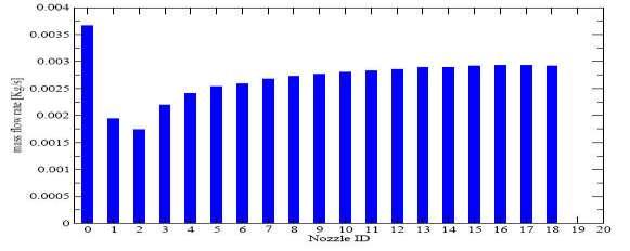
8 Objective Function Objective Function: Equal flow rate Baseline Design Optimized Design 8


9 Example Simple Sedan Sequential Tabs Define Control Region(s) 9

 Select control")

10 Deformation Definition Define constraint(s) (if any) Select control points and prescribe the relative ranges of motion 10


11 Optimizer Algorithms; Compass, Powell, Rosenbrock, Simplex, Torczon Auto Optimize! 11


12 Results Incompressible turbulent flow Objective Function; Minimize Drag Baseline Design Questions? Please contact ANSYS Tech support for help in applying this technology Optimized Design 12
13 RBF-Morph 13


14 RBF-Morph 14


15 How RBF-Morph Works? Once displacements are defined by the user at the source points, Radial Basis Function interpolation is used to derive the displacement at any location in the space, so it is also available at every grid node. The RBF problem definition is mesh independent, same set up can be applied to different meshes 15

16 External flow example 16
17 RBF-Morph main features Fully integrated within FLUENT and Workbench Easy to use Parallel calculation allows to morph large size models (many millions of cells) in a short time Mesh independent solution works with all element types (tetrahedral, hexahedral, polyhedral, etc.) Superposition of multiple RBF-solutions makes the FLUENT case truly parametric (only 1 mesh is stored) RBF-solution can also be applied on the CAD Precision: exact nodal movement and exact feature preservation. 17
 ship advancing steadly in calm water trim and sinkage fixed displaced volume as")
18 Test case description Ship hull: Series 60, C B =0.6 Conducted by Pranzitelli & Caridi external hydrodynamics multiphase flow (air & water) ship advancing steadly in calm water trim and sinkage fixed displaced volume as constraint resistance prediction Objective: Optimization of the hull shape with no displacement reduction Reduction of the resistance 18


19 workbench operator Process CAD Mesh ICEM-CFD Baseline sim. Fluent grid cells Workbench and RBF-morph setup Coarse 331,652 Medium 692,984 DOE RUNS Optimization Final solution Fine 1,274,742 C T ΔC T Coarse 5.81x % Medium 5.94x % Fine 5.96x10⁻³ 0% Exp.* 5.96x


20 workbench operator Process CAD Mesh ICEM-CFD Baseline sim. Fluent Symmetry Eight Section Morphing cross deformation plane domain sections fixed specified applied defined Workbench and RBF-morph setup DOE RUNS Optimization Final solution 20


21 workbench operator Process CAD Mesh ICEM-CFD Baseline sim. Fluent Workbench and RBF-morph setup DOE RUNS Parameters are defined and transferred to the parameter set bar for use with ANSYS DesignXplorer DX builds a DOE and drives Fluent and RBF Morph Optimization Final solution 21


22 ANSYS DesignXplorer Sensitivity analysis Results Input parameters Output parameters Response Surface DOE Settings Design of Experiments 45 Design Points Solved in Batch 22


23 Optimize with ANSYS DesignXplorer Optimize Baseline Optimized F x 6.83N 6.29N baseline 7.9% resistance reduction No volume reduction optimized 23
: 45 CPU*-hours Optimization: Minutes Without Workbench & RBF-Morph.")
24 Performance with RBF-Morph in Workbench: Mesh generation: 6 man-hours Fluent case setup: 1 man-hours Baseline simulation (coarse grid): 4 CPU*-hours Workbench and RBF-Morph setup:1 man-hours DOE (45 simulations): 45 CPU*-hours Optimization: Minutes Without Workbench & RBF-Morph...? Mesh generation (first mesh): 6 man-hours Geometry (CAD) and mesh modification for each case (considering mesh automation in ICEM-CFD): 1x45 = 45 man-hours Cases management (Fluent): 1x46 = 46 man-hours Cases execution: 4+45 = 49 CPU*-hours use of other optimization tools:?? 8 man hrs 2 CPU days ~100 man hrs 2 CPU days (optimistically) 24 *one Intel i7 quad-core processor, 2.8GHz
25 Fluent Adjoint 25
26 Preface The release of the adjoint solver in ANSYS Fluent 14 is the culmination of several years of R&D effort. This project was risky, but the rewards are great for ANSYS clients. There were a number of false starts and deadends. Writing an adjoint solver that meets the needs of the engineering community is not a trivial task. We are pleased to have come so far, and look forward to going much further. 26
27 What is an adjoint solution and how do we use those results? An adjoint solver allows specific information about a fluid system to be computed that is very difficult to gather otherwise. The adjoint solution itself is a set of derivatives. They are not particularly useful in their raw form and must be post-processed appropriately. The derivative of an engineering quantity with respect to all of the inputs for the system can be computed in a single calculation. Example: Sensitivity of the drag on an airfoil to its shape. There are 4 main ways in which these derivatives can be used: 1. Qualitative guidance on what can influence the performance of a system strongly. 2. Quantitative guidance on the anticipated effect of specific design changes. 3. Guidance on important factors in solver numerics. 4. Gradient-based design optimization. 27

28 GOAL: Identify features of a system design that are most influential in the performance of the system. EXAMPLE: How to use the results - Qualitative Sensitivity of the Drag on a NACA 0012 airfoil to changes in the shape of the airfoil. The shape sensitivity field is extracted from the adjoint solution in a postprocessing step. High sensitivity changes to shape have a big effect on drag Low sensitivity changes to shape have a small effect on drag 28
29 How to use the results - Quantitative GOAL: Identify specific system design changes that benefit the performance and quantify the improvement in performance that is anticipated. EXAMPLE: Design modifications to turning vanes in a 90 degree elbow to reduce the total pressure drop. The optimal adjustment that is made to the shape is defined by the shape sensitivity field (steepest descent algorithm). Effect of each change can be computed in advance based on linear extrapolation. Baseline Modified Original DP = Pa Expected change computed using the adjoint and linear extrapolation = 10.0 Pa Make the change and recompute the solution. Actual change = 9.0 Pa 29


30 How to use the results Solver Numerics GOAL: Identify aspects of the solver numerics and computational mesh that have a strong influence on quantities that are being computed that are of engineering interest. EXAMPLE: Use the adjoint solution to identify parts of the mesh where mesh adaption will benefit the computed drag by reducing the influence of discretization errors. Baseline Mesh Adapted Mesh Adapted Mesh Detail 30
![Dp tot [Pa] How to use the results Optimization GOAL: Perform a sequence of](/docs-images/76/74475320/images/31-1.jpg "automated design modifications to improve a specific performance measure for")


31 Dp tot [Pa] How to use the results Optimization GOAL: Perform a sequence of automated design modifications to improve a specific performance measure for a system EXAMPLE: Gradient-based optimization of the total pressure drop in a pipe. Flow solution is recomputed and the adjoint recomputed at each design iteration Initial design Final design 30% reduction in total pressure drop after 30 design iterations Iteration
32 How does an adjoint analysis fit into the familiar CFD workflow? Standard CFD Workflow elements Define a flow problem. Create a geometric representation of the problem and create a computational mesh. Setup and solve the flow problem. Post-process the results. If the design is not meeting performance requirements Use insight, experience and intuition to decide how to select design changes that will improve the performance of the system or Adjoint workflow elements Use the results to improve the design systematically using one of the 4 strategies outlined Pick an observation that is of engineering interest. Lift, drag, total pressure drop? Set up and solve the adjoint problem for this observation for the specific computed flow field Define adjoint solution advancement controls Set adjoint convergence criteria Initialize the adjoint solution field Iterate to convergence Post process 32
33 Supporting Technologies Mesh morphing Mesh morphing & Adjoint Data Mesh Morphing, Adjoint Data & Constraints 33


34 Mesh Morphing Once a desired change to the geometry of the system has been selected, how is that change to be made? Mesh morphing provides a convenient and powerful means of changing the geometry and the computational mesh. Use Bernstein polynomial-based morphing scheme discussed earlier 34
 Benefit of this approach is two-fold Smooths the surface sensitivity field Provides a smooth interior and boundary mesh deformation 35")
35 Mesh Morphing & Adjoint Data Example: Sensitivity of lift to surface shape Flow Select portions of the geometry to be modified Adjoint to deformation operation Surface shape sensitivity becomes control point sensitivity (chain rule for differentiation) Benefit of this approach is two-fold Smooths the surface sensitivity field Provides a smooth interior and boundary mesh deformation 35
36 Mesh Morphing, Adjoint Data & Constraints The adjoint solution is determined based on the specific flow physics of the problem in hand. The effect of other practical engineering constraints must be reconciled with the adjoint data to decide on an allowable design change. Example: Some walls within the control volume may be constrained not to move. A minimal adjustment is made to the control-point sensitivity field so that deformation of the fixed walls is eliminated. Fixed wall Fixed wall Moveable walls 36
37 Current Functionality ANSYS-Fluent flow solver has very broad scope Adjoint is configured to compute solutions based on some assumptions Steady, incompressible, laminar flow. Steady, incompressible, turbulent flow with standard wall functions. First-order discretization in space. Frozen turbulence. The primary flow solution does NOT need to be run with these restrictions Strong evidence that these assumptions do not undermine the utility of the adjoint solution data for engineering purposes. Fully parallelized Gradient algorithm for shape modification Mesh morphing using control points. Adjoint-based solution adaption 37
38 Current Functionality The adjoint solver is an addon that will be part of the Fluent 14 distribution. Documentation is available Theory Usage Tutorial Case study Training is available. Functionality is activated by loading the adjoint solver addon module. A new menu item is added at the top level. Limitations include unsupported models (porous media, MRF etc.), convergence can be challenging for large cases (5-10M+ cells) and cases that exhibit unsteady flow or strong shear flows Stabilized solution advancement algorithm is in place 38


39 User-Interface GUI Follow as closely as possible the same design layout as Fluent solver TUI Specify observable Adjoint solution advancement controls Residual monitors Initialization and iteration Post-processing: contours, vectors. Results reporting Mesh-morphing with pre-calculation of expected change in observable. /adjoint> controls morphing/ reporting/ monitors/ observable/ run/ 39
40 Examples 40

41 Total Pressure Drop in a Bend Full discrete adjoint for shape sensitivity Frozen turbulence Reduce total pressure drop, DP, through system Baseline 13 2 DP = Expect change 10.0 Actual change 9.0 DP = Expect change 8.9 Actual change 6.9 DP = Expect change 7.0 Actual change 3.1 DP = Total improvement of 8% 41

42 Total Pressure Drop in a Duct Flow residuals Flow Adjoint residuals Outflow Goal is to reduce the total pressure drop through the system Set up and solve the adjoint system with a total pressure drop objective function 42
 Geometry")


43 Total Pressure Drop in a Duct Total Pressure Drop (Pa) Geometry Predicted Result Original Modified Aggressive adjustment results in a 17% reduction in loss in just one design iteration 43
44 Summary The adjoint solver will be released with R14 An adjoint solver computes sensitivity data that can be used to aid with design decisions in 4 main ways: 1. Qualitative identification of critical parts of the system of interest. 2. Quantitative predictions of the optimal choice for a design change and a prediction of the effect of that change. 3. Aiding in the numerical analysis of the flow solution to improve solution quality. 4. Gradient-based optimization. Supporting technologies such as mesh morphing, and the application of design constraints, are seen as important. The adjoint solver for the present release is limited to steady incompressible flows, with other restrictions on models. 44
Shape optimisation using breakthrough technologies
 Shape optimisation using breakthrough technologies Compiled by Mike Slack Ansys Technical Services 2010 ANSYS, Inc. All rights reserved. 1 ANSYS, Inc. Proprietary Introduction Shape optimisation technologies
RBF Morph An Add-on Module for Mesh Morphing in ANSYS Fluent
 RBF Morph An Add-on Module for Mesh Morphing in ANSYS Fluent Gilles Eggenspieler Senior Product Manager 1 Morphing & Smoothing A mesh morpher is a tool capable of performing mesh modifications in order
Automated Design Exploration and Optimization. Clinton Smith, PhD CAE Support and Training PADT April 26, 2012
 Automated Design Exploration and Optimization Clinton Smith, PhD CAE Support and Training PADT April 26, 2012 1 Agenda The path to robust design A closer look at what DX offers Some examples 2 The Path
Automated Design Exploration and Optimization + HPC Best Practices
 Automated Design Exploration and Optimization + HPC Best Practices 1 Outline The Path to Robust Design ANSYS DesignXplorer Mesh Morphing and Optimizer RBF Morph Adjoint Solver HPC Best Practices 2 The
Optimisationfor CFD. ANSYS R14 Fluids Update Seminar. Milton Park, February 16 th, 2012 Sheffield, February 29 th, 2012 Aberdeen, March 8 th, 2012
 Optimisationfor CFD ANSYS R14 Fluids Update Seminar David Mann, ANSYS UK Ltd. Milton Park, February 16 th, 2012 Sheffield, February 29 th, 2012 Aberdeen, March 8 th, 2012 1 Agenda Optimisation Tools for
Introduction to ANSYS CFX
 Workshop 03 Fluid flow around the NACA0012 Airfoil 16.0 Release Introduction to ANSYS CFX 2015 ANSYS, Inc. March 13, 2015 1 Release 16.0 Workshop Description: The flow simulated is an external aerodynamics
Adjoint Solver Workshop
 Adjoint Solver Workshop Why is an Adjoint Solver useful? Design and manufacture for better performance: e.g. airfoil, combustor, rotor blade, ducts, body shape, etc. by optimising a certain characteristic
Shape Optimization for Aerodynamic Efficiency Using Adjoint Methods
 White Paper Shape Optimization for Aerodynamic Efficiency Using Adjoint Methods Adjoint solvers take a Computational Fluid Dynamics (CFD) flow solution and calculate the sensitivity of performance indicators
An advanced RBF Morph application: coupled CFD-CSM Aeroelastic Analysis of a Full Aircraft Model and Comparison to Experimental Data
 An advanced RBF Morph application: coupled CFD-CSM Aeroelastic Analysis of a Full Aircraft Model and Comparison to Experimental Data Dr. Marco Evangelos Biancolini Tor Vergata University, Rome, Italy Dr.
Auto Injector Syringe. A Fluent Dynamic Mesh 1DOF Tutorial
 Auto Injector Syringe A Fluent Dynamic Mesh 1DOF Tutorial 1 2015 ANSYS, Inc. June 26, 2015 Prerequisites This tutorial is written with the assumption that You have attended the Introduction to ANSYS Fluent
CFD VALIDATION FOR SURFACE COMBATANT 5415 STRAIGHT AHEAD AND STATIC DRIFT 20 DEGREE CONDITIONS USING STAR CCM+
 CFD VALIDATION FOR SURFACE COMBATANT 5415 STRAIGHT AHEAD AND STATIC DRIFT 20 DEGREE CONDITIONS USING STAR CCM+ by G. J. Grigoropoulos and I..S. Kefallinou 1. Introduction and setup 1. 1 Introduction The
Ansys Fluent R Michele Andreoli
 Ansys Fluent R 17.0 Michele Andreoli (m.andreoli@enginsoft.it) Table of contents User Interface Fluent Meshing Solver Numerics New features Innovative Solutions New User Interface: Ribbon-Driven Solver
Studies of the Continuous and Discrete Adjoint Approaches to Viscous Automatic Aerodynamic Shape Optimization
 Studies of the Continuous and Discrete Adjoint Approaches to Viscous Automatic Aerodynamic Shape Optimization Siva Nadarajah Antony Jameson Stanford University 15th AIAA Computational Fluid Dynamics Conference
Calculate a solution using the pressure-based coupled solver.
 Tutorial 19. Modeling Cavitation Introduction This tutorial examines the pressure-driven cavitating flow of water through a sharpedged orifice. This is a typical configuration in fuel injectors, and brings
Simulating Sinkage & Trim for Planing Boat Hulls. A Fluent Dynamic Mesh 6DOF Tutorial
 Simulating Sinkage & Trim for Planing Boat Hulls A Fluent Dynamic Mesh 6DOF Tutorial 1 Introduction Workshop Description This workshop describes how to perform a transient 2DOF simulation of a planing
Flow and Heat Transfer in a Mixing Elbow
 Flow and Heat Transfer in a Mixing Elbow Objectives The main objectives of the project are to learn (i) how to set up and perform flow simulations with heat transfer and mixing, (ii) post-processing and
Fluid structure interaction analysis: vortex shedding induced vibrations
 Fluid structure interaction analysis: vortex shedding induced vibrations N. Di Domenico, M. E. * University of Rome «Tor Vergata», Department of Enterprise Engineering «Mario Lucertini» A. Wade, T. Berg,
Simulation of Flow Development in a Pipe
 Tutorial 4. Simulation of Flow Development in a Pipe Introduction The purpose of this tutorial is to illustrate the setup and solution of a 3D turbulent fluid flow in a pipe. The pipe networks are common
Workbench Tutorial Minor Losses, Page 1 Tutorial Minor Losses using Pointwise and FLUENT
 Workbench Tutorial Minor Losses, Page 1 Tutorial Minor Losses using Pointwise and FLUENT Introduction This tutorial provides instructions for meshing two internal flows. Pointwise software will be used
Introduction to C omputational F luid Dynamics. D. Murrin
 Introduction to C omputational F luid Dynamics D. Murrin Computational fluid dynamics (CFD) is the science of predicting fluid flow, heat transfer, mass transfer, chemical reactions, and related phenomena
Verification and Validation of Turbulent Flow around a Clark-Y Airfoil
 Verification and Validation of Turbulent Flow around a Clark-Y Airfoil 1. Purpose 58:160 Intermediate Mechanics of Fluids CFD LAB 2 By Tao Xing and Fred Stern IIHR-Hydroscience & Engineering The University
Verification of Laminar and Validation of Turbulent Pipe Flows
 1 Verification of Laminar and Validation of Turbulent Pipe Flows 1. Purpose ME:5160 Intermediate Mechanics of Fluids CFD LAB 1 (ANSYS 18.1; Last Updated: Aug. 1, 2017) By Timur Dogan, Michael Conger, Dong-Hwan
CFD MODELING FOR PNEUMATIC CONVEYING
 CFD MODELING FOR PNEUMATIC CONVEYING Arvind Kumar 1, D.R. Kaushal 2, Navneet Kumar 3 1 Associate Professor YMCAUST, Faridabad 2 Associate Professor, IIT, Delhi 3 Research Scholar IIT, Delhi e-mail: arvindeem@yahoo.co.in
Simulation of Laminar Pipe Flows
 Simulation of Laminar Pipe Flows 57:020 Mechanics of Fluids and Transport Processes CFD PRELAB 1 By Timur Dogan, Michael Conger, Maysam Mousaviraad, Tao Xing and Fred Stern IIHR-Hydroscience & Engineering
Using Multiple Rotating Reference Frames
 Tutorial 10. Using Multiple Rotating Reference Frames Introduction Many engineering problems involve rotating flow domains. One example is the centrifugal blower unit that is typically used in automotive
RBF Morph: mesh morphing in OpenFoam
 RBF Morph: mesh morphing in OpenFoam Dr. Marco Evangelos Biancolini University of Rome Tor Vergata @ CINECA, 26-28 March 2014 Cineca - BOLOGNA RBF Morph Training PRACE School 2013 Session #1 General Introduction
Using Multiple Rotating Reference Frames
 Tutorial 9. Using Multiple Rotating Reference Frames Introduction Many engineering problems involve rotating flow domains. One example is the centrifugal blower unit that is typically used in automotive
Speed and Accuracy of CFD: Achieving Both Successfully ANSYS UK S.A.Silvester
 Speed and Accuracy of CFD: Achieving Both Successfully ANSYS UK S.A.Silvester 2010 ANSYS, Inc. All rights reserved. 1 ANSYS, Inc. Proprietary Content ANSYS CFD Introduction ANSYS, the company Simulation
Introduction to CFX. Workshop 2. Transonic Flow Over a NACA 0012 Airfoil. WS2-1. ANSYS, Inc. Proprietary 2009 ANSYS, Inc. All rights reserved.
 Workshop 2 Transonic Flow Over a NACA 0012 Airfoil. Introduction to CFX WS2-1 Goals The purpose of this tutorial is to introduce the user to modelling flow in high speed external aerodynamic applications.
Overview and Recent Developments of Dynamic Mesh Capabilities
 Overview and Recent Developments of Dynamic Mesh Capabilities Henrik Rusche and Hrvoje Jasak h.rusche@wikki-gmbh.de and h.jasak@wikki.co.uk Wikki Gmbh, Germany Wikki Ltd, United Kingdom 6th OpenFOAM Workshop,
Computational Fluid Dynamics autumn, 1st week
 Computational Fluid Dynamics 2016 autumn, 1st week 1 Tamás Benedek benedek [at] ara.bme.hu www.ara.bme.hu/~benedek/cfd/icem The most important rule: Dont use space or specific characters in: File names,
Strategies to Achieve Reliable and Accurate CFD Solutions
 Strategies to Achieve Reliable and Accurate CFD Solutions Mark Keating ANSYS UK 2010 ANSYS, Inc. All rights reserved. 1 ANSYS, Inc. Proprietary Agenda Why develop a CFD strategy? Pre-Processing Strategies
Coupled Analysis of FSI
 Coupled Analysis of FSI Qin Yin Fan Oct. 11, 2008 Important Key Words Fluid Structure Interface = FSI Computational Fluid Dynamics = CFD Pressure Displacement Analysis = PDA Thermal Stress Analysis = TSA
Appendix: To be performed during the lab session
 Appendix: To be performed during the lab session Flow over a Cylinder Two Dimensional Case Using ANSYS Workbench Simple Mesh Latest revision: September 18, 2014 The primary objective of this Tutorial is
Compressible Flow in a Nozzle
 SPC 407 Supersonic & Hypersonic Fluid Dynamics Ansys Fluent Tutorial 1 Compressible Flow in a Nozzle Ahmed M Nagib Elmekawy, PhD, P.E. Problem Specification Consider air flowing at high-speed through a
ANSYS FLUENT. Lecture 3. Basic Overview of Using the FLUENT User Interface L3-1. Customer Training Material
 Lecture 3 Basic Overview of Using the FLUENT User Interface Introduction to ANSYS FLUENT L3-1 Parallel Processing FLUENT can readily be run across many processors in parallel. This will greatly speed up
Verification and Validation of Turbulent Flow around a Clark-Y Airfoil
 1 Verification and Validation of Turbulent Flow around a Clark-Y Airfoil 1. Purpose ME:5160 Intermediate Mechanics of Fluids CFD LAB 2 (ANSYS 19.1; Last Updated: Aug. 7, 2018) By Timur Dogan, Michael Conger,
CDA Workshop Physical & Numerical Hydraulic Modelling. STAR-CCM+ Presentation
 CDA Workshop Physical & Numerical Hydraulic Modelling STAR-CCM+ Presentation ENGINEERING SIMULATION CFD FEA Mission Increase the competitiveness of companies through optimization of their product development
Isotropic Porous Media Tutorial
 STAR-CCM+ User Guide 3927 Isotropic Porous Media Tutorial This tutorial models flow through the catalyst geometry described in the introductory section. In the porous region, the theoretical pressure drop
Aerodynamic Study of a Realistic Car W. TOUGERON
 Aerodynamic Study of a Realistic Car W. TOUGERON Tougeron CFD Engineer 2016 Abstract This document presents an aerodynamic CFD study of a realistic car geometry. The aim is to demonstrate the efficiency
Coupled Simulation of Flow and Body Motion Using Overset Grids. Eberhard Schreck & Milovan Perić
 Coupled Simulation of Flow and Body Motion Using Overset Grids Eberhard Schreck & Milovan Perić Contents Dynamic Fluid-Body Interaction (DFBI) model in STAR-CCM+ Overset grids method in STAR-CCM+ Advantages
SIMULATION OF PROPELLER-SHIP HULL INTERACTION USING AN INTEGRATED VLM/RANSE SOLVER MODELING.
 SIMULATION OF PROPELLER-SHIP HULL INTERACTION USING AN INTEGRATED VLM/RANSE SOLVER MODELING. M.N.Senthil Prakash, Department of Ocean Engineering, IIT Madras, India V. Anantha Subramanian Department of
Taming OpenFOAM for Ship Hydrodynamics Applications
 Taming OpenFOAM for Ship Hydrodynamics Applications Sung-Eun Kim, Ph. D. Computational Hydromechanics Division (Code 5700) Naval Surface Warfare Center Carderock Division Background Target Applications
I. Introduction. Optimization Algorithm Components. Abstract for the 5 th OpenFOAM User Conference 2017, Wiesbaden - Germany
 An Aerodynamic Optimization Framework for the Automotive Industry, based on Continuous Adjoint and OpenFOAM E. Papoutsis-Kiachagias 1, V. Asouti 1, K. Giannakoglou 1, K. Gkagkas 2 1) National Technical
Design Exploration and Robust Design. Judd Kaiser Product Manager, ANSYS Workbench Platform
 Design Exploration and Robust Design Judd Kaiser Product Manager, ANSYS Workbench Platform 1 Agenda 2 What is Robust Design? At ANSYS Workbench Principles DesignXplorer ANSYS Vision What is Robust Design?
Pressure Drop Evaluation in a Pilot Plant Hydrocyclone
 Pressure Drop Evaluation in a Pilot Plant Hydrocyclone Fabio Kasper, M.Sc. Emilio Paladino, D.Sc. Marcus Reis, M.Sc. ESSS Carlos A. Capela Moraes, D.Sc. Dárley C. Melo, M.Sc. Petrobras Research Center
NUMERICAL INVESTIGATION OF THE FLOW BEHAVIOR INTO THE INLET GUIDE VANE SYSTEM (IGV)
") University of West Bohemia» Department of Power System Engineering NUMERICAL INVESTIGATION OF THE FLOW BEHAVIOR INTO THE INLET GUIDE VANE SYSTEM (IGV) Publication was supported by project: Budování excelentního
University of West Bohemia» Department of Power System Engineering NUMERICAL INVESTIGATION OF THE FLOW BEHAVIOR INTO THE INLET GUIDE VANE SYSTEM (IGV) Publication was supported by project: Budování excelentního
ANSYS AIM Tutorial Flow over an Ahmed Body
 Author(s): Sebastian Vecchi Created using ANSYS AIM 18.1 ANSYS AIM Tutorial Flow over an Ahmed Body Problem Specification Start Up Geometry Import Geometry Enclose Suppress Mesh Set Mesh Controls Generate
Tutorial: Simulating a 3D Check Valve Using Dynamic Mesh 6DOF Model And Diffusion Smoothing
 Tutorial: Simulating a 3D Check Valve Using Dynamic Mesh 6DOF Model And Diffusion Smoothing Introduction The purpose of this tutorial is to demonstrate how to simulate a ball check valve with small displacement
Commercial Implementations of Optimization Software and its Application to Fluid Dynamics Problems
 Commercial Implementations of Optimization Software and its Application to Fluid Dynamics Problems Szymon Buhajczuk, M.A.Sc SimuTech Group Toronto Fields Institute Optimization Seminar December 6, 2011
Lab 9: FLUENT: Transient Natural Convection Between Concentric Cylinders
 Lab 9: FLUENT: Transient Natural Convection Between Concentric Cylinders Objective: The objective of this laboratory is to introduce how to use FLUENT to solve both transient and natural convection problems.
Lecture 7: Mesh Quality & Advanced Topics. Introduction to ANSYS Meshing Release ANSYS, Inc. February 12, 2015
 Lecture 7: Mesh Quality & Advanced Topics 15.0 Release Introduction to ANSYS Meshing 1 2015 ANSYS, Inc. February 12, 2015 Overview In this lecture we will learn: Impact of the Mesh Quality on the Solution
Using a Single Rotating Reference Frame
 Tutorial 9. Using a Single Rotating Reference Frame Introduction This tutorial considers the flow within a 2D, axisymmetric, co-rotating disk cavity system. Understanding the behavior of such flows is
Modeling Unsteady Compressible Flow
 Tutorial 4. Modeling Unsteady Compressible Flow Introduction In this tutorial, FLUENT s density-based implicit solver is used to predict the timedependent flow through a two-dimensional nozzle. As an initial
Supersonic Flow Over a Wedge
 SPC 407 Supersonic & Hypersonic Fluid Dynamics Ansys Fluent Tutorial 2 Supersonic Flow Over a Wedge Ahmed M Nagib Elmekawy, PhD, P.E. Problem Specification A uniform supersonic stream encounters a wedge
Tutorial 17. Using the Mixture and Eulerian Multiphase Models
 Tutorial 17. Using the Mixture and Eulerian Multiphase Models Introduction: This tutorial examines the flow of water and air in a tee junction. First you will solve the problem using the less computationally-intensive
Using the Eulerian Multiphase Model for Granular Flow
 Tutorial 21. Using the Eulerian Multiphase Model for Granular Flow Introduction Mixing tanks are used to maintain solid particles or droplets of heavy fluids in suspension. Mixing may be required to enhance
1.2 Numerical Solutions of Flow Problems
 1.2 Numerical Solutions of Flow Problems DIFFERENTIAL EQUATIONS OF MOTION FOR A SIMPLIFIED FLOW PROBLEM Continuity equation for incompressible flow: 0 Momentum (Navier-Stokes) equations for a Newtonian
FLUENT Secondary flow in a teacup Author: John M. Cimbala, Penn State University Latest revision: 26 January 2016
 FLUENT Secondary flow in a teacup Author: John M. Cimbala, Penn State University Latest revision: 26 January 2016 Note: These instructions are based on an older version of FLUENT, and some of the instructions
ANSYS AIM 16.0 Overview. AIM Program Management
 1 2015 ANSYS, Inc. September 27, 2015 ANSYS AIM 16.0 Overview AIM Program Management 2 2015 ANSYS, Inc. September 27, 2015 Today s Simulation Challenges Leveraging simulation across engineering organizations
Direct Numerical Simulation of a Low Pressure Turbine Cascade. Christoph Müller
 Low Pressure NOFUN 2015, Braunschweig, Overview PostProcessing Experimental test facility Grid generation Inflow turbulence Conclusion and slide 2 / 16 Project Scale resolving Simulations give insight
Tutorial 1. Introduction to Using FLUENT: Fluid Flow and Heat Transfer in a Mixing Elbow
 Tutorial 1. Introduction to Using FLUENT: Fluid Flow and Heat Transfer in a Mixing Elbow Introduction This tutorial illustrates the setup and solution of the two-dimensional turbulent fluid flow and heat
Adjoint Optimization combined with mesh morphing for CFD applications
 Adjoint Optimization combined with mesh morphing for CFD applications Alberto Clarich*, Luca Battaglia*, Enrico Nobile**, Marco Evangelos Biancolini, Ubaldo Cella *ESTECO Spa, Italy. Email: engineering@esteco.com
OzenCloud Case Studies
 OzenCloud Case Studies Case Studies, April 20, 2015 ANSYS in the Cloud Case Studies: Aerodynamics & fluttering study on an aircraft wing using fluid structure interaction 1 Powered by UberCloud http://www.theubercloud.com
Computational Study of Laminar Flowfield around a Square Cylinder using Ansys Fluent
 MEGR 7090-003, Computational Fluid Dynamics :1 7 Spring 2015 Computational Study of Laminar Flowfield around a Square Cylinder using Ansys Fluent Rahul R Upadhyay Master of Science, Dept of Mechanical
SIMULATION OF FLOW AROUND KCS-HULL
 SIMULATION OF FLOW AROUND KCS-HULL Sven Enger (CD-adapco, Germany) Milovan Perić (CD-adapco, Germany) Robinson Perić (University of Erlangen-Nürnberg, Germany) 1.SUMMARY The paper describes results of
ANSYS Fluid Structure Interaction for Thermal Management and Aeroelasticity
 ANSYS Fluid Structure Interaction for Thermal Management and Aeroelasticity Phil Stopford Duxford Air Museum 11th May 2011 2011 2010 ANSYS, Inc. All rights reserved. 1 ANSYS, Inc. Proprietary Fluid Structure
Simulation of Turbulent Flow around an Airfoil
 1. Purpose Simulation of Turbulent Flow around an Airfoil ENGR:2510 Mechanics of Fluids and Transfer Processes CFD Lab 2 (ANSYS 17.1; Last Updated: Nov. 7, 2016) By Timur Dogan, Michael Conger, Andrew
Topology Optimization in Fluid Dynamics
 A Methodology for Topology Optimization in Fluid Dynamics 1 Chris Cowan Ozen Engineering, Inc. 1210 E. Arques Ave, Suite 207 Sunnyvale, CA 94085 info@ozeninc.com Ozen Engineering Inc. We are your local
Express Introductory Training in ANSYS Fluent Workshop 06 Using Moving Reference Frames and Sliding Meshes
 Express Introductory Training in ANSYS Fluent Workshop 06 Using Moving Reference Frames and Sliding Meshes Dimitrios Sofialidis Technical Manager, SimTec Ltd. Mechanical Engineer, PhD PRACE Autumn School
Missile External Aerodynamics Using Star-CCM+ Star European Conference 03/22-23/2011
 Missile External Aerodynamics Using Star-CCM+ Star European Conference 03/22-23/2011 StarCCM_StarEurope_2011 4/6/11 1 Overview 2 Role of CFD in Aerodynamic Analyses Classical aerodynamics / Semi-Empirical
Tutorial 2. Modeling Periodic Flow and Heat Transfer
 Tutorial 2. Modeling Periodic Flow and Heat Transfer Introduction: Many industrial applications, such as steam generation in a boiler or air cooling in the coil of an air conditioner, can be modeled as
NON-PARAMETRIC SHAPE OPTIMIZATION IN INDUSTRIAL CONTEXT
 NON-PARAMETRIC SHAPE OPTIMIZATION IN INDUSTRIAL CONTEXT Michael Böhm, Peter Clausen FE-DESIGN GmbH, Paris, April 3rd, 2012 Overview Introduction / FE-Design Optimization in Industry and Requirements Shape
Verification and Validation in CFD and Heat Transfer: ANSYS Practice and the New ASME Standard
 Verification and Validation in CFD and Heat Transfer: ANSYS Practice and the New ASME Standard Dimitri P. Tselepidakis & Lewis Collins ASME 2012 Verification and Validation Symposium May 3 rd, 2012 1 Outline
Tutorial: Hydrodynamics of Bubble Column Reactors
 Tutorial: Introduction The purpose of this tutorial is to provide guidelines and recommendations for solving a gas-liquid bubble column problem using the multiphase mixture model, including advice on solver
Adjoint Solver Advances, Tailored to Automotive Applications
 Adjoint Solver Advances, Tailored to Automotive Applications Stamatina Petropoulou s.petropoulou@iconcfd.com 1 Contents 1. Icon s Principal Work in FlowHead 2. Demonstration Cases 3. Icon s Further Development
Solution Recording and Playback: Vortex Shedding
 STAR-CCM+ User Guide 6663 Solution Recording and Playback: Vortex Shedding This tutorial demonstrates how to use the solution recording and playback module for capturing the results of transient phenomena.
ITTC Recommended Procedures and Guidelines
 Page 1 of 9 Table of Contents 1. OVERVIEW... 2 2. COMPUTATIONAL PROCEDURE.. 2 2.1 Preliminaries... 2 2.2 Code and Computer... 3 2.3 Ship Geometry, Computational Domain, and Boundary Conditions... 3 2.4
CFD Topology Optimization of Automotive Components
 CFD Topology Optimization of Automotive Components Dr.-Ing. Markus Stephan, Dr.-Ing. Dipl.-Phys. Pascal Häußler, Dipl.-Math. Michael Böhm FE-DESIGN GmbH, Karlsruhe, Germany Synopsis Automatic CFD optimization
Use 6DOF solver to calculate motion of the moving body. Create TIFF files for graphic visualization of the solution.
 Introduction The purpose of this tutorial is to provide guidelines and recommendations for setting up and solving a moving deforming mesh (MDM) case along with the six degree of freedom (6DOF) solver and
Self-Cultivation System
 Development of a Microorganism Incubator using CFD Simulations Self-Cultivation System A comfortable mixing incubator to grow microorganism for agricultural, animal husbandry and ocean agriculture industries
Workbench Tutorial Flow Over an Airfoil, Page 1 ANSYS Workbench Tutorial Flow Over an Airfoil
 Workbench Tutorial Flow Over an Airfoil, Page 1 ANSYS Workbench Tutorial Flow Over an Airfoil Authors: Scott Richards, Keith Martin, and John M. Cimbala, Penn State University Latest revision: 17 January
Application of Wray-Agarwal Turbulence Model for Accurate Numerical Simulation of Flow Past a Three-Dimensional Wing-body
 Washington University in St. Louis Washington University Open Scholarship Mechanical Engineering and Materials Science Independent Study Mechanical Engineering & Materials Science 4-28-2016 Application
COMPUTATIONAL FLUID DYNAMICS ANALYSIS OF ORIFICE PLATE METERING SITUATIONS UNDER ABNORMAL CONFIGURATIONS
 COMPUTATIONAL FLUID DYNAMICS ANALYSIS OF ORIFICE PLATE METERING SITUATIONS UNDER ABNORMAL CONFIGURATIONS Dr W. Malalasekera Version 3.0 August 2013 1 COMPUTATIONAL FLUID DYNAMICS ANALYSIS OF ORIFICE PLATE
Modeling External Compressible Flow
 Tutorial 3. Modeling External Compressible Flow Introduction The purpose of this tutorial is to compute the turbulent flow past a transonic airfoil at a nonzero angle of attack. You will use the Spalart-Allmaras
TUTORIAL#3. Marek Jaszczur. Boundary Layer on a Flat Plate W1-1 AGH 2018/2019
 TUTORIAL#3 Boundary Layer on a Flat Plate Marek Jaszczur AGH 2018/2019 W1-1 Problem specification TUTORIAL#3 Boundary Layer - on a flat plate Goal: Solution for boudary layer 1. Creating 2D simple geometry
Express Introductory Training in ANSYS Fluent Workshop 04 Fluid Flow Around the NACA0012 Airfoil
 Express Introductory Training in ANSYS Fluent Workshop 04 Fluid Flow Around the NACA0012 Airfoil Dimitrios Sofialidis Technical Manager, SimTec Ltd. Mechanical Engineer, PhD PRACE Autumn School 2013 -
Modeling Flow Through Porous Media
 Tutorial 7. Modeling Flow Through Porous Media Introduction Many industrial applications involve the modeling of flow through porous media, such as filters, catalyst beds, and packing. This tutorial illustrates
Thank you for downloading one of our ANSYS whitepapers we hope you enjoy it.
 Thank you! Thank you for downloading one of our ANSYS whitepapers we hope you enjoy it. Have questions? Need more information? Please don t hesitate to contact us! We have plenty more where this came from.
Introduction to Workbench Scripting & Customization ANSYS, Inc. November 29, 2012
 Introduction to Workbench Scripting & Customization 1 Outline Understanding the Workbench framework WB Journaling and Scripting Different Customization Methods Conclusion 2 Workbench Framework Application
Analysis Comparison between CFD and FEA of an Idealized Concept V- Hull Floor Configuration in Two Dimensions
 2010 NDIA GROUND VEHICLE SYSTEMS ENGINEERING AND TECHNOLOGY SYMPOSIUM MODELING & SIMULATION, TESTING AND VALIDATION (MSTV) MINI-SYMPOSIUM AUGUST 17-19 DEARBORN, MICHIGAN Analysis Comparison between CFD
This tutorial illustrates how to set up and solve a problem involving solidification. This tutorial will demonstrate how to do the following:
 Tutorial 22. Modeling Solidification Introduction This tutorial illustrates how to set up and solve a problem involving solidification. This tutorial will demonstrate how to do the following: Define a
Simulation and Validation of Turbulent Pipe Flows
 Simulation and Validation of Turbulent Pipe Flows ENGR:2510 Mechanics of Fluids and Transport Processes CFD LAB 1 (ANSYS 17.1; Last Updated: Oct. 10, 2016) By Timur Dogan, Michael Conger, Dong-Hwan Kim,
Hydro-elastic analysis of a propeller using CFD and FEM co-simulation
 Fifth International Symposium on Marine Propulsors smp 17, Espoo, Finland, June 2017 Hydro-elastic analysis of a propeller using CFD and FEM co-simulation Vesa Nieminen 1 1 VTT Technical Research Centre
Usage of CFX for Aeronautical Simulations
 Usage of CFX for Aeronautical Simulations Florian Menter Development Manager Scientific Coordination ANSYS Germany GmbH Overview Elements of CFD Technology for aeronautical simulations: Grid generation
Maximize automotive simulation productivity with ANSYS HPC and NVIDIA GPUs
 Presented at the 2014 ANSYS Regional Conference- Detroit, June 5, 2014 Maximize automotive simulation productivity with ANSYS HPC and NVIDIA GPUs Bhushan Desam, Ph.D. NVIDIA Corporation 1 NVIDIA Enterprise
CFD Application in Offshore Structures Design at PETROBRAS
 CFD Application in Offshore Structures Design at PETROBRAS Marcus Reis ESSS CFD Director Mooring System Design of Floating Production Systems; Current and Wind Loads; Wave Induced Drag Coefficients. Case
Introduction to ANSYS SOLVER FLUENT 12-1
 Introduction to ANSYS SOLVER FLUENT 12-1 Breadth of Technologies 10-2 Simulation Driven Product Development 10-3 Windshield Defroster Optimized Design 10-4 How Does CFD Work? 10-5 Step 1. Define Your Modeling
THE EFFECTS OF THE PLANFORM SHAPE ON DRAG POLAR CURVES OF WINGS: FLUID-STRUCTURE INTERACTION ANALYSES RESULTS
 March 18-20, 2013 THE EFFECTS OF THE PLANFORM SHAPE ON DRAG POLAR CURVES OF WINGS: FLUID-STRUCTURE INTERACTION ANALYSES RESULTS Authors: M.R. Chiarelli, M. Ciabattari, M. Cagnoni, G. Lombardi Speaker:
FFD, mesh morphing & reduced order models: Enablers for efficient aerodynamic shape optimization
 FFD, mesh morphing & reduced order models: Enablers for efficient aerodynamic shape optimization F Salmoiraghi, G Rozza SISSA mathlab A Scardigli, H Telib OPTIMAD engineering srl Outline 1. Prac'cal)problems)in)shape)op'miza'on)