4: Polygons and pixels
|
|
|
- Hugh Robertson
- 6 years ago
- Views:
Transcription
1 COMP711 Computer Graphics and Image Processing 4: Polygons and pixels 1 Introduction We ll look at Properties of polygons: convexity, winding, faces, normals Scan conversion of polygons Hidden surface removal with the Z-buffer Data structures for polygonal models Where do we get polygons from? 1
 3 What is a polygon?")
2 Polygons as building blocks The basic unit of D raster graphics is the pixel The most common basic unit of 3D graphics is the polygon The most common polygon is the triangle Many different types of 3D objects can be modelled well with meshes of polygons but there are other techniques too which don t involve polygons (e.g., volume rendering, particle systems) 3 What is a polygon? An ordered set of vertices (V 1 V 4 ) A set of edges between each pair of vertices (E 1 E 4 ) V 1 E 1 V The polygon (P) is then the space bounded by the vertices Some polygons are not so simple P E E 4 V 3 So we avoid polygons like that E 3 V 4 4
3 Polygon attributes: winding The order in which the edges connect the vertices gives a polygon a winding There are two winding orders: clockwise and counter clockwise (but which is which depends on which side you view from) Winding 1 We need to use a consistent winding for all the polygons in a scene Winding 5 Polygon attributes: faces If we have a consistent winding, then the polygon has two defined faces a front and a back 1 If all the vertices lie on plane, then we have a planar polygon (which is almost always what we want) 3 Front view 1 Triangles are always planar 3 Back view 6 3

![systems will only guarantee to draw planar polygons V 3 V V 4 V 1 V5 V 6 Here, [ V 1 V V 5 V 6 ] lie on one plane, but [ V V 3 V 4 V 5 ] lie on](/docs-images/77/76047403/images/4-2.jpg "another.")

4 Polygon attributes: faces Non-planar polygons have vertices that do not all lie on a single plane Although they have two sides they don t have obvious faces in the same way This can cause problems with some graphical algorithms so generally we assume our polygons are planar Most graphics systems will only guarantee to draw planar polygons V 3 V V 4 V 1 V5 V 6 Here, [ V 1 V V 5 V 6 ] lie on one plane, but [ V V 3 V 4 V 5 ] lie on another. This is a non-planar polygon 7 Polygon attributes: surface normal With a consistent winding order, we can define a property called the surface normal This is a vector perpendicular to the plane of the polygon We can use this to give a polygon a distinguishable front and back and also to describe its orientation in 3D space Orientation is an essential property used extensively in lighting calculations, collisions, culling Surface Normal Vector 8 4
5 The Cross Product is a vector, defined as follows: V 3 V 1 x1 x y1 z z1 y y 1 y x1 z z1 x = z 1 z x1 y y1 x V For two normalized vectors, their cross product is a third vector perpendicular to them both (forming a right handed system) V = 3 V V 1 9 Finding the surface normal 1. Choose a pair of sequential edges E 1 and E and compute their vectors Surface Normal N. Invert the direction of the first so they now emanate from their shared vertex 3. Normalize the vectors ^ E ^ -E 1 4. Their cross product will be the surface normal N = E ˆ? x Eˆ

6 Representing things with polygons How can we represent a scene using polygons? One option is to have a huge list of individual polygons, to colour them individually and to draw them all in order This is called polygon soup and has a number of undesirable properties 11 Problems with polygon soup Huge waste of storage space most models contain surfaces not individual polygons, so we could share vertices rather than replicate them per polygon Complete loss of semantics does a polygon belong to a cow or a table? Leads to brute force rendering, and makes interaction with the model complex 18,000 separate vertices, many repeated 1 6

7 Polygon meshes Use linked groups of polygons, or meshes, to represent surfaces Retains semantics of surface but reduces storage by sharing vertices and edges Helps with interaction Helps with structuring the model so we can manipulate it more easily 6,000 separate vertices, mostly unique/shared 13 Meshes: triangle strips 1 T1 T 3 T3 0 Add one new vertex get one new triangle 14 7
8 Meshes: triangle strips Collection of linked triangles Very widely used efficient N linked triangles can be defined using N+ vertices compared with 3N vertices if each triangle were defined separately 4 15 Triangle strip in OpenGL glbegin(gl_triangle_strip); glvertex3f(x0, y0, z0); glvertex3f(x1, y1, z1); glvertex3f(x, y, z); glvertex3f(x3, y3, z3); /* and other vertices */ glend();
9 Meshes: triangle fan Collection of linked triangles N linked triangles can be defined using N+ vertices compared with 3N vertices if each triangle were defined separately 1 17 Triangle fan in OpenGL glbegin(gl_triangle_fan); glvertex3f(x0, y0, z0); glvertex3f(x1, y1, z1); glvertex3f(x, y, z); /* and other vertices */ glend();
10 Meshes: quadrilateral strips Collection of linked quadrilaterals (a.k.a. quads) N quads can be defined using N+ vertices, compared with 4N separate vertices 19 Quad strip in OpenGL glbegin(gl_quad_strip); glvertex3f(x0, y0, z0); glvertex3f(x1, y1, z1); glvertex3f(x, y, z); glvertex3f(x3, y3, z3); /* and other vertices */ glend(); Tessellated into triangles during rendering


11 Meshes: quadrilateral meshes Collection of linked quadrilaterals Used in terrain modelling, and for approximating curved surfaces,1 4,1 3,1 5,1 6,1 Tessellated into triangles during 1,1 rendering 1, 1,3 1,4 N x M quads can be defined using (N+1) * (M+1) vertices, compared with 4*M*N separate vertices 1 From the model to the display We model in a 3D space, then take a view using a camera to create a D screen image Viewing Pipeline Vertices in World Coordinates Vertices in Pixel Coordinates 11
12 Getting the pixels: scan conversion Viewing Pipeline Vertices in World Coordinates Vertices in Pixel Coordinates 3 Scan-converting a line We sample the true geometry of the line, and approximate it using the nearest pixels available. 4 1
13 Bresenham s algorithm y = mx + c As we move horizontally x changes by 1 pixel So y n+1 = y n + m Round y n+1 to the nearest pixel Need to swap x and y according to gradient of the line Bresenham (1965) developed a fast algorithm using only integer arithmetic Still in use today Y X 5 Scan-converting a line We sample the true geometry of the line, and approximate it using the nearest pixels available. 6 13
14 Scan converting a polygon Viewing Pipeline Vertices in World Coordinates Vertices in Pixel Coordinates 7 Scan converting a polygon There are many approaches to scanconverting a polygon, and we ll look at two The polygon has been transformed by the viewing pipeline, so we know its (x,y,z) vertex coordinates in screen space The (x,y) coordinates corresponds to a pixel position The z coordinate is a measure of the vertex s distance from the eye (or camera ). We won t use that information just yet. 8 14
15 Scan converting a triangle We can scan-convert each of the edges 9 Scan converting a triangle Now we can process each row of pixels and fill in the remaining interior pixels 30 15
16 Scan converting a triangle In practice, this naïve approach is never used. There are far more efficient methods, which can be implemented in hardware 31 Scan converting a triangle efficiently One example is the sweep-line algorithm The algorithm steps down a pair of edges, starting in this example at (x1,y1), then goes down scanline by scanline, finding the start and end of the part of the scanline inside the triangle. Then it fills the pixels inside the triangle for that scanline. Efficient because we only need to compute the slopes of the edges (px and qx) once, at the beginning. It is, however, a floating point algorithm, and we have to keep rounding to the pixel grid. (x1, y1) Scanline N px qx Scanline N+1 (x, y) (x3, y3) 3 16

17 Hidden surface removal Question: viewing the world from a particular viewpoint, which parts of the world can we see, and which parts can we not see, because other objects (partially) block them? There are two fundamentally different approaches that we can take to solving this problem: We can solve it in world space. We can try to work it out geometrically in 3D, and then draw the result. This was the first approach used, ish, and it is extremely hard We can do it in display space. During scan-conversion, whenever we generate a pixel P, we determine whether some other 3D object, nearer to the eye, also maps to P. This is now the standard approach. 33 Cornell University Program of Computer Graphics 34 17


18 Cornell University Program of Computer Graphics 35 Cornell University Program of Computer Graphics 36 18
19 The Z-buffer (or depth-buffer) We introduce a new data structure called the Z-buffer For every pixel in the display memory, there is a corresponding entry in the Z-buffer The Z-buffer is used to keep a record of the z-value of each pixel Pixel memory Z-buffer memory Stores pixel colour Stores pixel z-depth 37 The Z-buffer algorithm 1. Initialise each pixel to desired background colour. Initialise each Z-buffer entry to MAXDEPTH (biggest possible number) 3. For each pixel P generated during scan-conversion of an object: IF z-coordinate of P < Z-BUFFER[P] THEN // i.e., the part of the 3D object that mapped to P // is nearer to the eye than any other part of the world // that has so far mapped to P Compute colour of P // lighting, texture later in the course Store colour in P Store (i.e., update) z-coordinate of P in Z-BUFFER[P] ELSE // something else has already mapped to P and is nearer to us // so don t change P 38 19

20 The Z-buffer: Z-fighting Lack of precision in the Z-buffer leads to incorrect rendering of pixels with similar z- values Especially horrible when animated stitching Grant James, zeuscmd.com Solution : glpolygonoffset() Z-fighting 39 Modelling with multiple objects 40 0

21 Structured models We can represent complex models using a hierarchical structure Ocwd.com Later in the course we ll look at how to give structure to complex models, using scene graphs Atoms Molecule Bonds For now we ll consider data structures for keeping track of polygons Spheres Triangles Cylinders Quads 41 Structured polygons Maintain a hierarchy of structure Model n Object n Surface n Polygons n Edges n Vertices Object Surfaces Polygons Edges/Vertices 4 1
22 General polygon mesh Flexible way to define linked polygons e 0 f0 e e Mesh data structure vertex list 0 edge list, indexing into the vertex list face list, indexing into the edge list e 0 f0 e 3 Face list f 0 Edge list e 0 e 1 e 1 x 0, y 0, z 0 x 1, y 1, z 1 x, y, z e 1 4 Vertex list x 3, y 3, z 3 44
23 Practicalities: file formats Meshes are often big Many different file formats The example here is a Wavefront obj file: 953 vertices ## Three-D Library generated.obj file ## data/womanheadh ## v v v v v v v v v Example: the obj file format List of vertices v x y z List of vertex normals vn x y z List of vertex texture coordinates vt s t List of faces f v1/vt1/vn1 v/vt/vn v3/vt3/vn3... List of groups g f1 f f3 Browse the full details, and get a feel for the problem, at
 by")

")

24 Creating Geometry: (1) by hand Making a polygon mesh by hand Mme Sylvie Gouraud (1971) 47 Creating Geometry: by hand Y Y O X O Z 48 4


25 Mme Gouraud (1971) 49 Case Study: manual reconstruction Chestergate: Project with Greater Manchester Police 50 5
26 51 5 6


 54 7")
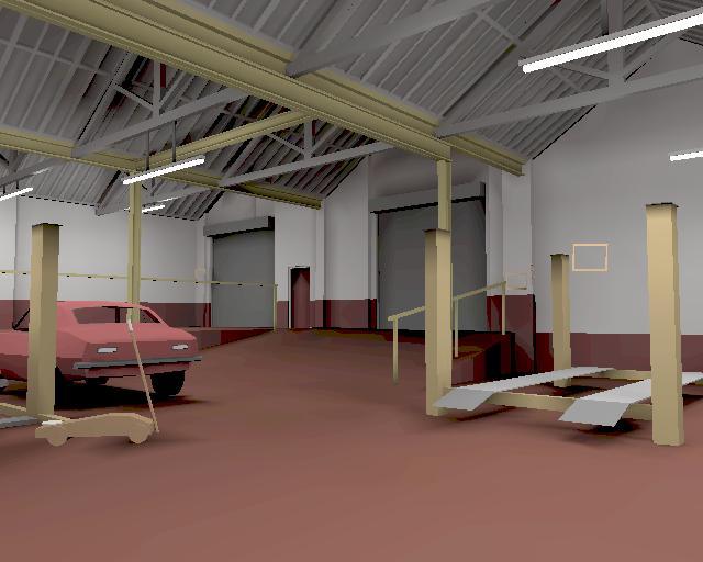
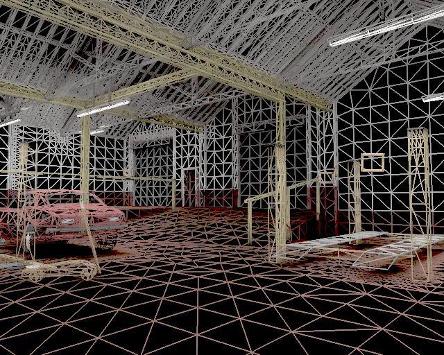
27 COMP711 33,000 polygons p NONE p NONE p Manual reconstruction may omit much detail This is very difficult to avoid (but how could we improve this?) 54 7
 How to do better (Research Topic) 55 Creating Geometry : () Interactive modelling")
28 Chestergate: Manual reconstruction Reconstruction performed entirely manually Measurements from architectural plans CAD model created in textual format Measurements from photographs Images and textures scanned from photographs 0 person-months of effort (approx) How to do better (Research Topic) 55 Creating Geometry : () Interactive modelling 56 8


29 Creating Geometry : Interactive modelling Google SketchUp 57 Creating Geometry: (3) Directly from the world Laser scanning 58 9
 59")


30 Mme Gouraud (1999) 59 Capture geometry directly from images/video Important area of ongoing research (see COMP37111) 60 30
The Traditional Graphics Pipeline
 Last Time? The Traditional Graphics Pipeline Participating Media Measuring BRDFs 3D Digitizing & Scattering BSSRDFs Monte Carlo Simulation Dipole Approximation Today Ray Casting / Tracing Advantages? Ray
The Traditional Graphics Pipeline
 Final Projects Proposals due Thursday 4/8 Proposed project summary At least 3 related papers (read & summarized) Description of series of test cases Timeline & initial task assignment The Traditional Graphics
The Traditional Graphics Pipeline
 Last Time? The Traditional Graphics Pipeline Reading for Today A Practical Model for Subsurface Light Transport, Jensen, Marschner, Levoy, & Hanrahan, SIGGRAPH 2001 Participating Media Measuring BRDFs
EECE 478. Learning Objectives. Learning Objectives. Rasterization & Scenes. Rasterization. Compositing
 EECE 478 Rasterization & Scenes Rasterization Learning Objectives Be able to describe the complete graphics pipeline. Describe the process of rasterization for triangles and lines. Compositing Manipulate
Rendering. Converting a 3D scene to a 2D image. Camera. Light. Rendering. View Plane
 Rendering Pipeline Rendering Converting a 3D scene to a 2D image Rendering Light Camera 3D Model View Plane Rendering Converting a 3D scene to a 2D image Basic rendering tasks: Modeling: creating the world
2: Introducing image synthesis. Some orientation how did we get here? Graphics system architecture Overview of OpenGL / GLU / GLUT
 COMP27112 Computer Graphics and Image Processing 2: Introducing image synthesis Toby.Howard@manchester.ac.uk 1 Introduction In these notes we ll cover: Some orientation how did we get here? Graphics system
How shapes are represented in 3D Graphics. Aims and objectives By the end of the lecture you will be able to describe
 Today s lecture Today we will learn about The mathematics of 3D space vectors How shapes are represented in 3D Graphics Modelling shapes as polygons Aims and objectives By the end of the lecture you will
COMP30019 Graphics and Interaction Scan Converting Polygons and Lines
 COMP30019 Graphics and Interaction Scan Converting Polygons and Lines Department of Computer Science and Software Engineering The Lecture outline Introduction Scan conversion Scan-line algorithm Edge coherence
graphics pipeline computer graphics graphics pipeline 2009 fabio pellacini 1
 graphics pipeline computer graphics graphics pipeline 2009 fabio pellacini 1 graphics pipeline sequence of operations to generate an image using object-order processing primitives processed one-at-a-time
graphics pipeline computer graphics graphics pipeline 2009 fabio pellacini 1
 graphics pipeline computer graphics graphics pipeline 2009 fabio pellacini 1 graphics pipeline sequence of operations to generate an image using object-order processing primitives processed one-at-a-time
Hidden surface removal. Computer Graphics
 Lecture Hidden Surface Removal and Rasterization Taku Komura Hidden surface removal Drawing polygonal faces on screen consumes CPU cycles Illumination We cannot see every surface in scene We don t want
Topic #1: Rasterization (Scan Conversion)
") Topic #1: Rasterization (Scan Conversion) We will generally model objects with geometric primitives points, lines, and polygons For display, we need to convert them to pixels for points it s obvious but
Topic #1: Rasterization (Scan Conversion) We will generally model objects with geometric primitives points, lines, and polygons For display, we need to convert them to pixels for points it s obvious but
The Rendering Pipeline (1)
") The Rendering Pipeline (1) Alessandro Martinelli alessandro.martinelli@unipv.it 30 settembre 2014 The Rendering Pipeline (1) Rendering Architecture First Rendering Pipeline Second Pipeline: Illumination
The Rendering Pipeline (1) Alessandro Martinelli alessandro.martinelli@unipv.it 30 settembre 2014 The Rendering Pipeline (1) Rendering Architecture First Rendering Pipeline Second Pipeline: Illumination
Graphics and Interaction Rendering pipeline & object modelling
 433-324 Graphics and Interaction Rendering pipeline & object modelling Department of Computer Science and Software Engineering The Lecture outline Introduction to Modelling Polygonal geometry The rendering
Triangle Rasterization
 Triangle Rasterization Computer Graphics COMP 770 (236) Spring 2007 Instructor: Brandon Lloyd 2/07/07 1 From last time Lines and planes Culling View frustum culling Back-face culling Occlusion culling
2D rendering takes a photo of the 2D scene with a virtual camera that selects an axis aligned rectangle from the scene. The photograph is placed into
 2D rendering takes a photo of the 2D scene with a virtual camera that selects an axis aligned rectangle from the scene. The photograph is placed into the viewport of the current application window. A pixel
Real-Time Graphics Architecture
 Real-Time Graphics Architecture Kurt Akeley Pat Hanrahan http://www.graphics.stanford.edu/courses/cs448a-01-fall Rasterization Outline Fundamentals Examples Special topics (Depth-buffer, cracks and holes,
CS 465 Program 4: Modeller
 CS 465 Program 4: Modeller out: 30 October 2004 due: 16 November 2004 1 Introduction In this assignment you will work on a simple 3D modelling system that uses simple primitives and curved surfaces organized
Project 1, 467. (Note: This is not a graphics class. It is ok if your rendering has some flaws, like those gaps in the teapot image above ;-)
") Project 1, 467 Purpose: The purpose of this project is to learn everything you need to know for the next 9 weeks about graphics hardware. What: Write a 3D graphics hardware simulator in your language of
Project 1, 467 Purpose: The purpose of this project is to learn everything you need to know for the next 9 weeks about graphics hardware. What: Write a 3D graphics hardware simulator in your language of
CS451Real-time Rendering Pipeline
 1 CS451Real-time Rendering Pipeline JYH-MING LIEN DEPARTMENT OF COMPUTER SCIENCE GEORGE MASON UNIVERSITY Based on Tomas Akenine-Möller s lecture note You say that you render a 3D 2 scene, but what does
FROM VERTICES TO FRAGMENTS. Lecture 5 Comp3080 Computer Graphics HKBU
 FROM VERTICES TO FRAGMENTS Lecture 5 Comp3080 Computer Graphics HKBU OBJECTIVES Introduce basic implementation strategies Clipping Scan conversion OCTOBER 9, 2011 2 OVERVIEW At end of the geometric pipeline,
CS 4731: Computer Graphics Lecture 21: Raster Graphics: Drawing Lines. Emmanuel Agu
 CS 4731: Computer Graphics Lecture 21: Raster Graphics: Drawing Lines Emmanuel Agu 2D Graphics Pipeline Clipping Object World Coordinates Applying world window Object subset window to viewport mapping
CSCI 4620/8626. Coordinate Reference Frames
 CSCI 4620/8626 Computer Graphics Graphics Output Primitives Last update: 2014-02-03 Coordinate Reference Frames To describe a picture, the world-coordinate reference frame (2D or 3D) must be selected.
COMP30019 Graphics and Interaction Rendering pipeline & object modelling
 COMP30019 Graphics and Interaction Rendering pipeline & object modelling Department of Computer Science and Software Engineering The Lecture outline Introduction to Modelling Polygonal geometry The rendering
Lecture outline. COMP30019 Graphics and Interaction Rendering pipeline & object modelling. Introduction to modelling
 Lecture outline COMP30019 Graphics and Interaction Rendering pipeline & object modelling Department of Computer Science and Software Engineering The Introduction to Modelling Polygonal geometry The rendering
Real-Time Graphics Architecture
 Real-Time Graphics Architecture Kurt Akeley Pat Hanrahan http://www.graphics.stanford.edu/courses/cs448a-01-fall Geometry Outline Vertex and primitive operations System examples emphasis on clipping Primitive
Graphics Hardware and Display Devices
 Graphics Hardware and Display Devices CSE328 Lectures Graphics/Visualization Hardware Many graphics/visualization algorithms can be implemented efficiently and inexpensively in hardware Facilitates interactive
Drawing Fast The Graphics Pipeline
 Drawing Fast The Graphics Pipeline CS559 Spring 2016 Lecture 10 February 25, 2016 1. Put a 3D primitive in the World Modeling Get triangles 2. Figure out what color it should be Do ligh/ng 3. Position
Computer Graphics. - Rasterization - Philipp Slusallek
 Computer Graphics - Rasterization - Philipp Slusallek Rasterization Definition Given some geometry (point, 2D line, circle, triangle, polygon, ), specify which pixels of a raster display each primitive
Topics. From vertices to fragments
 Topics From vertices to fragments From Vertices to Fragments Assign a color to every pixel Pass every object through the system Required tasks: Modeling Geometric processing Rasterization Fragment processing
Advanced Computer Graphics
 Advanced Computer Graphics Lecture 2: Modeling (1): Polygon Meshes Bernhard Jung TU-BAF, Summer 2007 Overview Computer Graphics Icon: Utah teapot Polygon Meshes Subdivision Polygon Mesh Optimization high-level:
Parametric description
 Examples: surface of revolution Vase Torus Parametric description Parameterization for a subdivision curve Modeling Polygonal meshes Graphics I Faces Face based objects: Polygonal meshes OpenGL is based
COMP3421. Particle Systems, Rasterisation
 COMP3421 Particle Systems, Rasterisation Particle systems Some visual phenomena are best modelled as collections of small particles. Examples: rain, snow, fire, smoke, dust Particle systems Particles are
Geometry Primitives. Computer Science Department University of Malta. Sandro Spina Computer Graphics and Simulation Group. CGSG Geometry Primitives
 Geometry Primitives Sandro Spina Computer Graphics and Simulation Group Computer Science Department University of Malta 1 The Building Blocks of Geometry The objects in our virtual worlds are composed
CMSC427 Final Practice v2 Fall 2017
 CMSC427 Final Practice v2 Fall 2017 This is to represent the flow of the final and give you an idea of relative weighting. No promises that knowing this will predict how you ll do on the final. Some questions
Performance OpenGL Programming (for whatever reason)
") Performance OpenGL Programming (for whatever reason) Mike Bailey Oregon State University Performance Bottlenecks In general there are four places a graphics system can become bottlenecked: 1. The computer
Performance OpenGL Programming (for whatever reason) Mike Bailey Oregon State University Performance Bottlenecks In general there are four places a graphics system can become bottlenecked: 1. The computer
RASTERIZING POLYGONS IN IMAGE SPACE
 On-Line Computer Graphics Notes RASTERIZING POLYGONS IN IMAGE SPACE Kenneth I. Joy Visualization and Graphics Research Group Department of Computer Science University of California, Davis A fundamental
OpenGL: Open Graphics Library. Introduction to OpenGL Part II. How do I render a geometric primitive? What is OpenGL
 OpenGL: Open Graphics Library Introduction to OpenGL Part II CS 351-50 Graphics API ( Application Programming Interface) Software library Layer between programmer and graphics hardware (and other software
CS452/552; EE465/505. Clipping & Scan Conversion
 CS452/552; EE465/505 Clipping & Scan Conversion 3-31 15 Outline! From Geometry to Pixels: Overview Clipping (continued) Scan conversion Read: Angel, Chapter 8, 8.1-8.9 Project#1 due: this week Lab4 due:
Volume Shadows Tutorial Nuclear / the Lab
 Volume Shadows Tutorial Nuclear / the Lab Introduction As you probably know the most popular rendering technique, when speed is more important than quality (i.e. realtime rendering), is polygon rasterization.
Realtime 3D Computer Graphics Virtual Reality
 Realtime 3D Computer Graphics Virtual Reality From Vertices to Fragments Overview Overall goal recapitulation: Input: World description, e.g., set of vertices and states for objects, attributes, camera,
Renderer Implementation: Basics and Clipping. Overview. Preliminaries. David Carr Virtual Environments, Fundamentals Spring 2005
 INSTITUTIONEN FÖR SYSTEMTEKNIK LULEÅ TEKNISKA UNIVERSITET Renderer Implementation: Basics and Clipping David Carr Virtual Environments, Fundamentals Spring 2005 Feb-28-05 SMM009, Basics and Clipping 1
Computer Graphics (CS 543) Lecture 10: Rasterization and Antialiasing
 Lecture 10: Rasterization and Antialiasing") Computer Graphics (CS 543) Lecture 10: Rasterization and Antialiasing Prof Emmanuel Agu Computer Science Dept. Worcester Polytechnic Institute (WPI) Recall: Rasterization Rasterization (scan conversion)
Computer Graphics (CS 543) Lecture 10: Rasterization and Antialiasing Prof Emmanuel Agu Computer Science Dept. Worcester Polytechnic Institute (WPI) Recall: Rasterization Rasterization (scan conversion)
CSE 167: Introduction to Computer Graphics Lecture #10: View Frustum Culling
 CSE 167: Introduction to Computer Graphics Lecture #10: View Frustum Culling Jürgen P. Schulze, Ph.D. University of California, San Diego Fall Quarter 2015 Announcements Project 4 due tomorrow Project
From Vertices to Fragments: Rasterization. Reading Assignment: Chapter 7. Special memory where pixel colors are stored.
 From Vertices to Fragments: Rasterization Reading Assignment: Chapter 7 Frame Buffer Special memory where pixel colors are stored. System Bus CPU Main Memory Graphics Card -- Graphics Processing Unit (GPU)
Pipeline Operations. CS 4620 Lecture 10
 Pipeline Operations CS 4620 Lecture 10 2008 Steve Marschner 1 Hidden surface elimination Goal is to figure out which color to make the pixels based on what s in front of what. Hidden surface elimination
Painter s HSR Algorithm
 Painter s HSR Algorithm Render polygons farthest to nearest Similar to painter layers oil paint Viewer sees B behind A Render B then A Depth Sort Requires sorting polygons (based on depth) O(n log n) complexity
Orthogonal Projection Matrices. Angel and Shreiner: Interactive Computer Graphics 7E Addison-Wesley 2015
 Orthogonal Projection Matrices 1 Objectives Derive the projection matrices used for standard orthogonal projections Introduce oblique projections Introduce projection normalization 2 Normalization Rather
CS 543: Computer Graphics. Rasterization
 CS 543: Computer Graphics Rasterization Robert W. Lindeman Associate Professor Interactive Media & Game Development Department of Computer Science Worcester Polytechnic Institute gogo@wpi.edu (with lots
0. Introduction: What is Computer Graphics? 1. Basics of scan conversion (line drawing) 2. Representing 2D curves
 2. Representing 2D curves") CSC 418/2504: Computer Graphics Course web site (includes course information sheet): http://www.dgp.toronto.edu/~elf Instructor: Eugene Fiume Office: BA 5266 Phone: 416 978 5472 (not a reliable way) Email:
CSC 418/2504: Computer Graphics Course web site (includes course information sheet): http://www.dgp.toronto.edu/~elf Instructor: Eugene Fiume Office: BA 5266 Phone: 416 978 5472 (not a reliable way) Email:
Tópicos de Computação Gráfica Topics in Computer Graphics 10509: Doutoramento em Engenharia Informática. Chap. 2 Rasterization.
 Tópicos de Computação Gráfica Topics in Computer Graphics 10509: Doutoramento em Engenharia Informática Chap. 2 Rasterization Rasterization Outline : Raster display technology. Basic concepts: pixel, resolution,
Fall CSCI 420: Computer Graphics. 7.1 Rasterization. Hao Li.
 Fall 2015 CSCI 420: Computer Graphics 7.1 Rasterization Hao Li http://cs420.hao-li.com 1 Rendering Pipeline 2 Outline Scan Conversion for Lines Scan Conversion for Polygons Antialiasing 3 Rasterization
AutoCAD DWG Drawing Limitations in SAP 3D Visual Enterprise 9.0 FP02
 AutoCAD DWG Drawing Limitations in SAP 3D Visual Enterprise 9.0 FP02 AutoCAD Import Limitations The following is a list of AutoCAD features that will not give an expected viewable when using SAP 3D Visual
Computer Graphics. Prof. Feng Liu. Fall /21/2016
 Computer Graphics Prof. Feng Liu Fall 2016 http://www.cs.pdx.edu/~fliu/courses/cs447/ 11/21/2016 Last time Polygon Mesh and Modeling 2 Today Modeling Technologies Final Exam: 12:30-2:00, December 7, 2016
Announcements. Written Assignment 2 is out see the web page. Computer Graphics
 Announcements Written Assignment 2 is out see the web page 1 Texture and other Mappings Shadows Texture Mapping Bump Mapping Displacement Mapping Environment Mapping Watt Chapter 8 COMPUTER GRAPHICS 15-462
3D Object Representation
 3D Object Representation Object Representation So far we have used the notion of expressing 3D data as points(or vertices) in a Cartesian or Homogeneous coordinate system. We have simplified the representation
CS 498 VR. Lecture 18-4/4/18. go.illinois.edu/vrlect18
 CS 498 VR Lecture 18-4/4/18 go.illinois.edu/vrlect18 Review and Supplement for last lecture 1. What is aliasing? What is Screen Door Effect? 2. How image-order rendering works? 3. If there are several
Rasterizing triangles
 Rasterizing triangles We know how to project the vertices of a triangle in our model onto pixel centers. To draw the complete triangle, we have to decide which pixels to turn on. For now, let s assume
CS130 : Computer Graphics Lecture 2: Graphics Pipeline. Tamar Shinar Computer Science & Engineering UC Riverside
 CS130 : Computer Graphics Lecture 2: Graphics Pipeline Tamar Shinar Computer Science & Engineering UC Riverside Raster Devices and Images Raster Devices - raster displays show images as a rectangular array
CGT 581 G Geometric Modeling Surfaces (part I)
") CGT 581 G Geometric Modeling Surfaces (part I) Bedrich Benes, Ph.D. Purdue University Department of Computer Graphics Technology Polygonal Representation The common representation is a mesh of triangles
CGT 581 G Geometric Modeling Surfaces (part I) Bedrich Benes, Ph.D. Purdue University Department of Computer Graphics Technology Polygonal Representation The common representation is a mesh of triangles
Texture. Texture Mapping. Texture Mapping. CS 475 / CS 675 Computer Graphics. Lecture 11 : Texture
 Texture CS 475 / CS 675 Computer Graphics Add surface detail Paste a photograph over a surface to provide detail. Texture can change surface colour or modulate surface colour. Lecture 11 : Texture http://en.wikipedia.org/wiki/uv_mapping
CS 475 / CS 675 Computer Graphics. Lecture 11 : Texture
 CS 475 / CS 675 Computer Graphics Lecture 11 : Texture Texture Add surface detail Paste a photograph over a surface to provide detail. Texture can change surface colour or modulate surface colour. http://en.wikipedia.org/wiki/uv_mapping
TDA362/DIT223 Computer Graphics EXAM (Same exam for both CTH- and GU students)
") TDA362/DIT223 Computer Graphics EXAM (Same exam for both CTH- and GU students) Saturday, January 13 th, 2018, 08:30-12:30 Examiner Ulf Assarsson, tel. 031-772 1775 Permitted Technical Aids None, except
TDA362/DIT223 Computer Graphics EXAM (Same exam for both CTH- and GU students) Saturday, January 13 th, 2018, 08:30-12:30 Examiner Ulf Assarsson, tel. 031-772 1775 Permitted Technical Aids None, except
Drawing Fast The Graphics Pipeline
 Drawing Fast The Graphics Pipeline CS559 Fall 2016 Lectures 10 & 11 October 10th & 12th, 2016 1. Put a 3D primitive in the World Modeling 2. Figure out what color it should be 3. Position relative to the
TSBK03 Screen-Space Ambient Occlusion
 TSBK03 Screen-Space Ambient Occlusion Joakim Gebart, Jimmy Liikala December 15, 2013 Contents 1 Abstract 1 2 History 2 2.1 Crysis method..................................... 2 3 Chosen method 2 3.1 Algorithm
CSCI 4620/8626. Computer Graphics Attributes of Graphics Primitives (Chapter 5)
") CSCI 4620/8626 Computer Graphics Attributes of Graphics Primitives (Chapter 5) Last update: 2015-03-02 Non-Fill Methods While polygons can be filled (with patterns or colors), they can also be displayed
CSCI 4620/8626 Computer Graphics Attributes of Graphics Primitives (Chapter 5) Last update: 2015-03-02 Non-Fill Methods While polygons can be filled (with patterns or colors), they can also be displayed
Werner Purgathofer
 Einführung in Visual Computing 186.822 Visible Surface Detection Werner Purgathofer Visibility in the Rendering Pipeline scene objects in object space object capture/creation ti modeling viewing projection
Rendering If we have a precise computer representation of the 3D world, how realistic are the 2D images we can generate? What are the best way to mode
 Graphic Pipeline 1 Rendering If we have a precise computer representation of the 3D world, how realistic are the 2D images we can generate? What are the best way to model 3D world? How to render them?
Computer Graphics 7 - Rasterisation
 Computer Graphics 7 - Rasterisation Tom Thorne Slides courtesy of Taku Komura www.inf.ed.ac.uk/teaching/courses/cg Overview Line rasterisation Polygon rasterisation Mean value coordinates Decomposing polygons
CSCI 420 Computer Graphics Lecture 14. Rasterization. Scan Conversion Antialiasing [Angel Ch. 6] Jernej Barbic University of Southern California
![CSCI 420 Computer Graphics Lecture 14. Rasterization. Scan Conversion Antialiasing [Angel Ch. 6] Jernej Barbic University of Southern California](/thumbs/86/93458757.jpg "CSCI 420 Computer Graphics Lecture 14. Rasterization. Scan Conversion Antialiasing [Angel Ch. 6] Jernej Barbic University of Southern California") CSCI 420 Computer Graphics Lecture 14 Rasterization Scan Conversion Antialiasing [Angel Ch. 6] Jernej Barbic University of Southern California 1 Rasterization (scan conversion) Final step in pipeline:
CSCI 420 Computer Graphics Lecture 14 Rasterization Scan Conversion Antialiasing [Angel Ch. 6] Jernej Barbic University of Southern California 1 Rasterization (scan conversion) Final step in pipeline:
CS 130 Exam I. Fall 2015
 S 3 Exam I Fall 25 Name Student ID Signature You may not ask any questions during the test. If you believe that there is something wrong with a question, write down what you think the question is trying
CSE 167: Introduction to Computer Graphics Lecture #5: Rasterization. Jürgen P. Schulze, Ph.D. University of California, San Diego Fall Quarter 2015
 CSE 167: Introduction to Computer Graphics Lecture #5: Rasterization Jürgen P. Schulze, Ph.D. University of California, San Diego Fall Quarter 2015 Announcements Project 2 due tomorrow at 2pm Grading window
Scene Management. Video Game Technologies 11498: MSc in Computer Science and Engineering 11156: MSc in Game Design and Development
 Video Game Technologies 11498: MSc in Computer Science and Engineering 11156: MSc in Game Design and Development Chap. 5 Scene Management Overview Scene Management vs Rendering This chapter is about rendering
2D Drawing Primitives
 THE SIERPINSKI GASKET We use as a sample problem the drawing of the Sierpinski gasket an interesting shape that has a long history and is of interest in areas such as fractal geometry. The Sierpinski gasket
Computer Graphics. Prof. Feng Liu. Fall /14/2016
 Computer Graphics Prof. Feng Liu Fall 2016 http://www.cs.pdx.edu/~fliu/courses/cs447/ 11/14/2016 Last time Texture Mapping 2 Mid-term 3 Today Mesh and Modeling 4 The Story So Far We ve looked at images
L1 - Introduction. Contents. Introduction of CAD/CAM system Components of CAD/CAM systems Basic concepts of graphics programming
 L1 - Introduction Contents Introduction of CAD/CAM system Components of CAD/CAM systems Basic concepts of graphics programming 1 Definitions Computer-Aided Design (CAD) The technology concerned with the
CS Rasterization. Junqiao Zhao 赵君峤
 CS10101001 Rasterization Junqiao Zhao 赵君峤 Department of Computer Science and Technology College of Electronics and Information Engineering Tongji University Vector Graphics Algebraic equations describe
COMP371 COMPUTER GRAPHICS
 COMP371 COMPUTER GRAPHICS LECTURE 14 RASTERIZATION 1 Lecture Overview Review of last class Line Scan conversion Polygon Scan conversion Antialiasing 2 Rasterization The raster display is a matrix of picture
Rendering. Basic Math Review. Rasterizing Lines and Polygons Hidden Surface Remove Multi-pass Rendering with Accumulation Buffers.
 Rendering Rasterizing Lines and Polygons Hidden Surface Remove Multi-pass Rendering with Accumulation Buffers Basic Math Review Slope-Intercept Formula For Lines Given a third point on the line: P = (X,Y)
CSE528 Computer Graphics: Theory, Algorithms, and Applications
 CSE528 Computer Graphics: Theory, Algorithms, and Applications Hong Qin State University of New York at Stony Brook (Stony Brook University) Stony Brook, New York 11794--4400 Tel: (631)632-8450; Fax: (631)632-8334
Real-Time Graphics Architecture
 Real-Time Graphics Architecture Lecture 5: Rasterization Kurt Akeley Pat Hanrahan http://graphics.stanford.edu/cs448-07-spring/ Rasterization Outline Fundamentals System examples Special topics (Depth-buffer,
Rasterization. Rasterization (scan conversion) Digital Differential Analyzer (DDA) Rasterizing a line. Digital Differential Analyzer (DDA)
 Digital Differential Analyzer (DDA) Rasterizing a line. Digital Differential Analyzer (DDA)") CSCI 420 Computer Graphics Lecture 14 Rasterization Jernej Barbic University of Southern California Scan Conversion Antialiasing [Angel Ch. 6] Rasterization (scan conversion) Final step in pipeline: rasterization
CSCI 420 Computer Graphics Lecture 14 Rasterization Jernej Barbic University of Southern California Scan Conversion Antialiasing [Angel Ch. 6] Rasterization (scan conversion) Final step in pipeline: rasterization
The Application Stage. The Game Loop, Resource Management and Renderer Design
 1 The Application Stage The Game Loop, Resource Management and Renderer Design Application Stage Responsibilities 2 Set up the rendering pipeline Resource Management 3D meshes Textures etc. Prepare data
Spring 2011 Prof. Hyesoon Kim
 Spring 2011 Prof. Hyesoon Kim Application Geometry Rasterizer CPU Each stage cane be also pipelined The slowest of the pipeline stage determines the rendering speed. Frames per second (fps) Executes on
Homework #2 and #3 Due Friday, October 12 th and Friday, October 19 th
 Homework #2 and #3 Due Friday, October 12 th and Friday, October 19 th 1. a. Show that the following sequences commute: i. A rotation and a uniform scaling ii. Two rotations about the same axis iii. Two
Module Contact: Dr Stephen Laycock, CMP Copyright of the University of East Anglia Version 1
 UNIVERSITY OF EAST ANGLIA School of Computing Sciences Main Series PG Examination 2013-14 COMPUTER GAMES DEVELOPMENT CMPSME27 Time allowed: 2 hours Answer any THREE questions. (40 marks each) Notes are
9. Three Dimensional Object Representations
 9. Three Dimensional Object Representations Methods: Polygon and Quadric surfaces: For simple Euclidean objects Spline surfaces and construction: For curved surfaces Procedural methods: Eg. Fractals, Particle
Meshing and Geometry
 Meshing and Geometry Points in OpenGL glbegin(gl_points); glvertex2fv(p0); glvertex2fv(p1); p7 p0 p1 glvertex2fv(p2); glvertex2fv(p3); p6 p2 glvertex2fv(p4); glvertex2fv(p5); p5 p3 glvertex2fv(p6); glvertex2fv(p7);
CHAPTER 1 Graphics Systems and Models 3
 ?????? 1 CHAPTER 1 Graphics Systems and Models 3 1.1 Applications of Computer Graphics 4 1.1.1 Display of Information............. 4 1.1.2 Design.................... 5 1.1.3 Simulation and Animation...........
HomeWork 2 Rasterization
 HomeWork 2 Rasterization Fall 2012 Submitted By - Nitin Agrahara Ravikumar 73714398 The First Part: Rasterization As required by the homework, the display function of the smooth program is hijacked and
CSE528 Computer Graphics: Theory, Algorithms, and Applications
 CSE528 Computer Graphics: Theory, Algorithms, and Applications Hong Qin State University of New York at Stony Brook (Stony Brook University) Stony Brook, New York 11794--4400 Tel: (631)632-8450; Fax: (631)632-8334
CSE 167: Introduction to Computer Graphics Lecture #18: More Effects. Jürgen P. Schulze, Ph.D. University of California, San Diego Fall Quarter 2016
 CSE 167: Introduction to Computer Graphics Lecture #18: More Effects Jürgen P. Schulze, Ph.D. University of California, San Diego Fall Quarter 2016 Announcements TA evaluations CAPE Final project blog
Scanline Rendering 2 1/42
 Scanline Rendering 2 1/42 Review 1. Set up a Camera the viewing frustum has near and far clipping planes 2. Create some Geometry made out of triangles 3. Place the geometry in the scene using Transforms
Illumination and Geometry Techniques. Karljohan Lundin Palmerius
 Illumination and Geometry Techniques Karljohan Lundin Palmerius Objectives Complex geometries Translucency Huge areas Really nice graphics! Shadows Graceful degradation Acceleration Optimization Straightforward
Computer Graphics and GPGPU Programming
 Computer Graphics and GPGPU Programming Donato D Ambrosio Department of Mathematics and Computer Science and Center of Excellence for High Performace Computing Cubo 22B, University of Calabria, Rende 87036,
From Ver(ces to Fragments: Rasteriza(on
 From Ver(ces to Fragments: Rasteriza(on From Ver(ces to Fragments 3D vertices vertex shader rasterizer fragment shader final pixels 2D screen fragments l determine fragments to be covered l interpolate
Robust Stencil Shadow Volumes. CEDEC 2001 Tokyo, Japan
 Robust Stencil Shadow Volumes CEDEC 2001 Tokyo, Japan Mark J. Kilgard Graphics Software Engineer NVIDIA Corporation 2 Games Begin to Embrace Robust Shadows 3 John Carmack s new Doom engine leads the way
Announcements. Midterms graded back at the end of class Help session on Assignment 3 for last ~20 minutes of class. Computer Graphics
 Announcements Midterms graded back at the end of class Help session on Assignment 3 for last ~20 minutes of class 1 Scan Conversion Overview of Rendering Scan Conversion Drawing Lines Drawing Polygons
Visibility: Z Buffering
 University of British Columbia CPSC 414 Computer Graphics Visibility: Z Buffering Week 1, Mon 3 Nov 23 Tamara Munzner 1 Poll how far are people on project 2? preferences for Plan A: status quo P2 stays
CS 130 Final. Fall 2015
 CS 130 Final Fall 2015 Name Student ID Signature You may not ask any questions during the test. If you believe that there is something wrong with a question, write down what you think the question is trying