Chapter 7 Practical Considerations in Modeling. Chapter 7 Practical Considerations in Modeling
|
|
|
- Augustus Stafford
- 6 years ago
- Views:
Transcription
1 CIVL 7/8117 1/43 Chapter 7 Learning Objectives To present concepts that should be considered when modeling for a situation by the finite element method, such as aspect ratio, symmetry, natural subdivisions, sizing of elements and the h, p, and r methods of refinement, concentrated loads and infinite stress, infinite medium, and connecting different kinds of elements To describe some of the approximations inherent in finite element solutions To illustrate convergence of solution and introduce the patch test for convergence of solution Chapter 7 Learning Objectives To discuss the interpretation of stresses in an element, including a common method of averaging the nodal values (also called smoothing) To present a flowchart of typical finite element processes used for the analysis of plane stress and plane strain To describe a computer assisted step-by-step solution of a bicycle wrench To demonstrate various real-world applications where plane stress/strain element models are applicable
2 CIVL 7/8117 2/43 Introduction In this section we will discuss some modeling considerations and guidelines, including mesh size, natural subdivisions, and the use of symmetry and associated boundary conditions. We will also introduce the concept of static condensation, which enables us to apply the basis of the CST stiffness matrix to a quadrilateral element. Finite Element Modeling Finite element modeling is partly an art guided by visualizing physical interactions taking place within a body. In modeling the user is confronted with the difficult task of understanding physical behavior taking place and understanding the physical behavior of various elements available for use. Matching the appropriate finite element to the physical behavior being modeling is one of many decisions that must be made by the modeler. Understanding the boundary conditions can be one of the most difficult tasks a modeler must face in construction a useable finite element model.


3 CIVL 7/8117 3/43 Aspect Ratio and Element Shape The aspect ratio is define as the ratio of the longest dimension to the shortest dimension of a quadrilateral element. In general, as the aspect ratio increases, the inaccuracy of the finite element solution increases. Good Bad Aspect Ratio and Element Shape Consider the five different finite element model shown in the figure below.

4 CIVL 7/8117 4/43 Aspect Ratio and Element Shape A plot of the resulting error in the displacement at point A of the beam verse aspect ratio is given. Aspect Ratio and Element Shape In addition, the numerical answers are given in the following table. Case Aspect Ratio Number of Nodes Number of Elements Point A Point B % Error Exact Solution
 aspect")

5 CIVL 7/8117 5/43 Aspect Ratio and Element Shape In general, elements that yield the best results are compact and regular in shape will: (1) aspect ratios near one; and (2) corner angles of quadrilaterals near 90. Minimum Support Conditions to Suppress Rigid Body Motions in 2D stable stable unstable

6 CIVL 7/8117 6/43 Use of Symmetry The use of symmetry will often expedite the modeling of a problem. Symmetry allows us to consider a reduced problem instead of the actual problem. This will allow us to use a finer discretization of element with less computational cost. Use of Symmetry The use of symmetry will often expedite the modeling of a problem.
7 CIVL 7/8117 7/43 Use of Symmetry The use of symmetry will often expedite the modeling of a problem. Use of Symmetry The use of symmetry will often expedite the modeling of a problem.
8 CIVL 7/8117 8/43 Use of Symmetry The use of symmetry will often expedite the modeling of a problem. Use of Symmetry The use of symmetry will often expedite the modeling of a problem.
9 CIVL 7/8117 9/43 Natural Subdivisions at Discontinuities There are a variety of natural subdivisions for finite element discretizations. For example, natural locations of nodes occur at concentrated loads or discontinuities in loading, other types of boundary conditions, and abrupt changes in geometry of materials. Sizing of Elements and Mesh Refinement A discretization depends on the geometry of the structure, the loading, and the boundary conditions. For example, areas of high, rapidity changing stresses require a finer mesh than regions where the stress is constant.

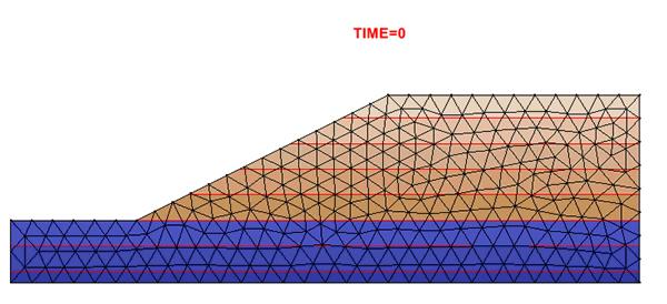
10 CIVL 7/ /43 Where Finer Meshes Should Be Used Use of Symmetry Here the use of symmetry is applied to a soil mass subjected to a foundation loading (66 nodes and 50 elements).
11 CIVL 7/ /43 Use of Symmetry Note that at the place of symmetry the displacements in the direction perpendicular to the plane must be zero. Use of Symmetry This is modeled by rollers at nodes 2-6.
12 CIVL 7/ /43 Use of Symmetry The figure below illustrates the use of triangular elements for transitions from smaller quadrilaterals to larger quadrilaterals. Use of Symmetry The transitions are required since CST elements do not have immediate nodes along their edges.


13 CIVL 7/ /43 Use of Symmetry If an element had an intermediate node, the resulting equations would be inconsistent with the energy formulation for the CST equations. Use of Symmetry

14 CIVL 7/ /43 Natural Subdivisions at Discontinuities Elements Must Not Cross Interfaces
15 CIVL 7/ /43 Natural Subdivisions at Discontinuities Mesh Revision (Refinement) Mesh revision or refinement is used to increase the accuracy of the results produced by a finite element model. First, start with a basic mesh using the fewest, reasonable number of elements, and obtain a benchmark result. Then refine the model by doing actions like increasing the mesh density and compare the results. This process continues until the results converge to some user-defined criteria. Consider this original mesh for the discussion of types of methods:
16 CIVL 7/ /43 Mesh Revision (Refinement) Consider this original mesh for the discussion of types of methods: h Method of Refinement In the h method, we use the particular element based on the shape functions for that element. Elements of the same kind are then added or made smaller. Uniform or non-uniform refinements are possible as shown below:
17 CIVL 7/ /43 p Method of Refinement In the p method, the polynomial p is increased to higher-order polynomials based on the degree of accuracy specified. These iterations are repeated until a convergence is reached. r Method of Refinement In the r method, the nodes are rearranged or relocated without changing the number of elements of the polynomial degree of the field quantities.

18 CIVL 7/ /43 Infinite Medium A typical example of infinite medium is a soil foundation problem. The guideline for the finite element model is that enough material must be included such that the displacements at nodes and stresses within the elements become negligibly small at locations far from the foundation load. The level of discretization can be determined by a trail-anderror procedure in which the horizontal and vertical distances from the load are varied and the resulting effects on the displacements and stresses are observed. Infinite Medium For a homogeneous soil mass, experience has shown the influence of a footing becomes insignificant if the horizontal distance of the model is taken as approximately four and six times the width of the footing and the vertical distance is taken as approximately four to ten times the width of the footing.


19 CIVL 7/ /43 Infinite Medium For a homogeneous soil mass, experience has shown the influence of a footing becomes insignificant if the horizontal distance of the model is taken as approximately four and six times the width of the footing and the vertical distance is taken as approximately four to ten times the width of the footing. Infinite Medium For a homogeneous soil mass, experience has shown the influence of a footing becomes insignificant if the horizontal distance of the model is taken as approximately four and six times the width of the footing and the vertical distance is taken as approximately four to ten times the width of the footing.

20 CIVL 7/ /43 Checking the Model The discretized finite element model should be checked carefully before results are computed. Ideally, a model should be checked by an analyst not involved in the preparation of the model, who is then more likely to be objective. Preprocessors with their detailed graphical display capabilities now make it comparatively easy to find errors, particularly with a misplaced node or missing element or a misplaced load or boundary condition. Preprocessors include the ability to color, shrink, rotate, and section a model mesh. Checking the Results and Typical Postprocessor Results An analyst should probability spend as much time processing, checking, and analyzing results as spent in data preparation.

.")
21 CIVL 7/ /43 Checking the Results and Typical Postprocessor Results An analyst should probability spend as much time processing, checking, and analyzing results as spent in data preparation. Checking the Results and Typical Postprocessor Results The wrench in this example is modeled by 307 constraint strain triangular elements (plane stress assumption). Below is a plot of the deformed shape of the wrench over the original mesh.

22 CIVL 7/ /43 Checking the Results and Typical Postprocessor Results Equilibrium and Compatibility of Finite Element Results An approximate solution for a stress analysis problem using the finite element method based on assumed displacement fields does not generally satisfy all the requirements for equilibrium and compatibility that an exact theory-ofelasticity solution satisfies. However, remember that relatively few exact solutions exist. Hence, the finite element method is a very practical one for obtaining reasonable, but approximate, numerical solutions.
23 CIVL 7/ /43 Equilibrium and Compatibility of Finite Element Results We now describe some of the approximations generally inherent with finite element solutions. 1. Equilibrium of nodal forces and moments is satisfied. This is true because the global equation F = Kd is a nodal equilibrium equation whose solution for d is such that the sums of all forces and moments applied to each node are zero. Equilibrium of the whole structure is also satisfied because the structure reactions are included in the global forces, and hence, in the nodal equilibrium equations. Equilibrium and Compatibility of Finite Element Results We now describe some of the approximations generally inherent with finite element solutions. 2. Equilibrium within an element is not always satisfied. However, for the constant-strain bar and the constantstrain triangle, element equilibrium is satisfied. Also the cubic displacement function is shown to satisfy the basic beam equilibrium differential equation, and hence, to satisfy element force and moment equilibrium.
24 CIVL 7/ /43 Equilibrium and Compatibility of Finite Element Results We now describe some of the approximations generally inherent with finite element solutions. 3. Equilibrium is not usually satisfied between elements. A differential element including parts of two adjacent finite elements is usually not in equilibrium (see the figure below). Equilibrium and Compatibility of Finite Element Results We now describe some of the approximations generally inherent with finite element solutions. 3. Equilibrium is not usually satisfied between elements. A differential element including parts of two adjacent finite elements is usually not in equilibrium (see the figure below).
25 CIVL 7/ /43 Equilibrium and Compatibility of Finite Element Results We now describe some of the approximations generally inherent with finite element solutions. 3. Equilibrium is not usually satisfied between elements. For line elements, such as used for truss and frame analysis, interelement equilibrium is satisfied. However, for two- and three-dimensional elements, interelement equilibrium is not usually satisfied. Also, the coarseness of the mesh causes this lack of interelement equilibrium to be even more pronounced. Equilibrium and Compatibility of Finite Element Results We now describe some of the approximations generally inherent with finite element solutions. 4. Compatibility is satisfied within an element as long as the element displacement field is continuous; hence, individual elements do not tear apart. 5. In the formulation of the element equations, compatibility is invoked at the nodes. Hence, elements remain connected at their common nodes. Similarly, the structure remains connected to its support nodes because boundary conditions are invoked at these nodes.
26 CIVL 7/ /43 Equilibrium and Compatibility of Finite Element Results We now describe some of the approximations generally inherent with finite element solutions. 6. Compatibility may or may not be satisfied along interelement boundaries. For line elements such as bars and beams, interelement boundaries are merely nodes. The constant-strain triangle remain straight sided when deformed and therefore, interelement compatibility exists for these elements. Incompatible elements, those that allow gaps or overlaps between elements, can be acceptable and even desirable. Convergence of Solution When the mesh size is reduced - that is the number of elements is increased - we are ensured of monotonic convergence of the solution when compatible and complete displacement functions are used.
27 CIVL 7/ /43 Convergence of Solution When the mesh size is reduced - that is the number of elements is increased - we are ensured of monotonic convergence of the solution when compatible and complete displacement functions are used. Convergence of Solution When the mesh size is reduced - that is the number of elements is increased - we are ensured of monotonic convergence of the solution when compatible and complete displacement functions are used. Case Number of Elements Number of Nodes Aspect Ratio Point A Exact Solution
28 CIVL 7/ /43 Patch Test The Patch test is used to test the convergence of a solution of an element being used in the model. The test requires that the element must be able to accommodate both rigid-body motion and a constant state of strain, as both are possible within a structure. The test can also be applied to determine if sufficient Gauss points have been used in the numerical integration process to evaluate the stiffness matrix for isoparametric formulations. Convergence of Solution When the mesh size is reduced - that is the number of elements is increased - we are ensured of monotonic convergence of the solution when compatible and complete displacement functions are used.


29 CIVL 7/ /43 Convergence of Solution When the mesh size is reduced - that is the number of elements is increased - we are ensured of monotonic convergence of the solution when compatible and complete displacement functions are used. Interpretation of Stresses In the stiffness or displacement formulation of the finite element method, used in this course, the primary quantities determined are the interelement nodal displacements of the assemblage. Secondary quantities, such as stress and strain, are computed based on these nodal displacements. In the case of the bar and constant-strain triangles, stresses are constant over the element. For these elements, it is common practice to assign the stress to the centroid of the element with acceptable results.
30 CIVL 7/ /43 Interpretation of Stresses An alternative procedure sometimes is to use an average (possibly weighted) value of the stresses evaluated at each node of the element. This averaging method is often based interpolating the element nodal values using the element shape functions. The averaging method is called smoothing. While the results from smoothing may be pleasing to the eye, they may not indicate potential problems with the model and the results. Interpretation of Stresses You should always view the unsmoothed contour plots as well. Highly discontinuous contours between elements in a region of an unsmoothed plot indicate modeling problems and typically require additional refinement of the element mesh in the suspect region.
31 CIVL 7/ /43 Static Condensation Let s consider the concept of static condensation and used it to develop the stiffness matrix of a quadrilateral element. Consider a general quadrilateral element as shown below. Static Condensation An imaginary node 5 is temporary introduced at the intersection of the diagonals of the quadrilateral to create four triangles.
32 CIVL 7/ /43 Static Condensation We can superimpose the stiffness matrices of the four triangles to create the stiffness matrix of the quadrilateral element, where the internal imaginary node 5 degrees of freedom are said to be condensed out so that they never enter into the final equations. Static Condensation Let s start by partitioning the equilibrium equations: K K d F e e K21 K 22di Fi where d i is the vector of displacements corresponding to the imaginary internal node, F i is the vector of loads at the internal node, and d e and F e are the actual displacements and loads, respectively. Rewriting the above equations we gives: K d K d F 11 e 12 i e K d K d F 21 e 22 i i
33 CIVL 7/ /43 Static Condensation Solving the second equations for d i gives: d K K d K F 1 1 i e 22 i Substituting the above equation, we obtain the condensed equilibrium equation: kd F c c c where k K K K K c F F K K F 1 c e i where k c and F c are called the condensed stiffness matrix and the condensed load vector, respectively. Static Condensation An advantage of the four-cst quadrilaterals is that the solution becomes less dependent on the skew of the subdivision mesh. The skew means a directional stiffness bias that is built into a model through certain discretization patterns.
34 CIVL 7/ /43 Static Condensation The stiffness matrix of a typical triangular element, call it element 1, labeled with nodes 1, 2, and 5 is given as: (1) (1) (1) k11 k12 k 15 (1) (1) (1) (1) k k21 k22 k25 (1) (1) (1) k51 k52 k 55 where k (1) ij is a 2 x 2 matrix. Static Condensation The assembled stiffness matrix for the quadrilateral is: k ( u, v ) ( u, v ) ( u, v ) ( u, v ) ( u, v ) k k k 0 k k k k k (1) (4) (1) (2) (2) (3) (3) (4) k51 k k k k k k k k k (1) (4) (1) (4) (1) (4) (1) (1) (2) (2) (1) (2) k21 k22 k22 k23 0 k25 k25 (2) (2) (3) (3) (2) (3) 0 k32 k33 k33 k34 k35 k35 (4) (3) (3) (4) (3) (4) k41 0 k43 k44 k44 k45 k45 (1) (2) (3) (4) 55 55
35 CIVL 7/ /43 Example Problem Consider the quadrilateral with internal node 5 and dimensions as shown below. Apply the static condensation technique. Using the CST stiffness matrix for plain strain, we get: (1) (3) [ k ] [ k ] E Example Problem Consider the quadrilateral with internal node 5 and dimensions as shown below. Apply the static condensation technique. Using the CST stiffness matrix for plain strain, we get: (2) (4) [ k ] [ k ] E
36 CIVL 7/ /43 Example Problem The resulting assembled matrix before static condensation is: Example Problem The resulting assembled matrix before static condensation is:

37 CIVL 7/ /43 Flowchart for the Solution of Place Stress/Strain Problems The following flowchart is typical for a finite element process used for the analysis of plane stress and plane strain problems. Flowchart for the Solution of Place Stress/Strain Problems


38 CIVL 7/ /43 Flowchart for the Solution of Place Stress/Strain Problems A bicycle company is disappointed with the negative feedback they have received on their latest model, and they have pinpointed the problem to an outdated bicycle crank design. They have outsourced the task of analyzing the crank to you, providing you with the geometry of the bicycle crank and attached pedal shaft shown below. Flowchart for the Solution of Place Stress/Strain Problems

39 CIVL 7/ /43 Flowchart for the Solution of Place Stress/Strain Problems Flowchart for the Solution of Place Stress/Strain Problems


40 CIVL 7/ /43 Flowchart for the Solution of Place Stress/Strain Problems Flowchart for the Solution of Place Stress/Strain Problems Coarser Mesh Finer Mesh DMX in in SMX 25,308 psi 27,942 psi The maximum displacement at the tip of shaft is 1.9% greater and the maximum stress is 10% greater


41 CIVL 7/ /43 Flowchart for the Solution of Place Stress/Strain Problems Flowchart for the Solution of Place Stress/Strain Problems Below is a finite element model and the von Mises stress plot for a beam welded to a column by top and bottom fillet welds. The material is steel with E = 205 GPa and = 0.25

42 CIVL 7/ /43 Flowchart for the Solution of Place Stress/Strain Problems After mesh refinement around the top weld to double the number of elements in the weld, the maximum Von Mises stress was determined to be 87.3 Mpa compares reasonably well with that obtained by the classical method where a value of 94 MPa was obtained. Problems 14. Do problems 7.2, 7.3, and 7.4 on pages in your textbook A First Course in the Finite Element Method by D. Logan. 15. Work problems 7.13, 7.16, and 7.22 on pages in your textbook A First Course in the Finite Element Method by D. Logan.
43 CIVL 7/ /43 End of Chapter 7
Finite Element Method. Chapter 7. Practical considerations in FEM modeling
 Finite Element Method Chapter 7 Practical considerations in FEM modeling Finite Element Modeling General Consideration The following are some of the difficult tasks (or decisions) that face the engineer
Guidelines for proper use of Plate elements
 Guidelines for proper use of Plate elements In structural analysis using finite element method, the analysis model is created by dividing the entire structure into finite elements. This procedure is known
Finite Element Analysis Prof. Dr. B. N. Rao Department of Civil Engineering Indian Institute of Technology, Madras. Lecture - 36
 Finite Element Analysis Prof. Dr. B. N. Rao Department of Civil Engineering Indian Institute of Technology, Madras Lecture - 36 In last class, we have derived element equations for two d elasticity problems
Revised Sheet Metal Simulation, J.E. Akin, Rice University
 Revised Sheet Metal Simulation, J.E. Akin, Rice University A SolidWorks simulation tutorial is just intended to illustrate where to find various icons that you would need in a real engineering analysis.
COMPUTER AIDED ENGINEERING. Part-1
 COMPUTER AIDED ENGINEERING Course no. 7962 Finite Element Modelling and Simulation Finite Element Modelling and Simulation Part-1 Modeling & Simulation System A system exists and operates in time and space.
Module: 2 Finite Element Formulation Techniques Lecture 3: Finite Element Method: Displacement Approach
 11 Module: 2 Finite Element Formulation Techniques Lecture 3: Finite Element Method: Displacement Approach 2.3.1 Choice of Displacement Function Displacement function is the beginning point for the structural
Module 1: Introduction to Finite Element Analysis. Lecture 4: Steps in Finite Element Analysis
 25 Module 1: Introduction to Finite Element Analysis Lecture 4: Steps in Finite Element Analysis 1.4.1 Loading Conditions There are multiple loading conditions which may be applied to a system. The load
CHAPTER 1. Introduction
 ME 475: Computer-Aided Design of Structures 1-1 CHAPTER 1 Introduction 1.1 Analysis versus Design 1.2 Basic Steps in Analysis 1.3 What is the Finite Element Method? 1.4 Geometrical Representation, Discretization
Beams. Lesson Objectives:
 Beams Lesson Objectives: 1) Derive the member local stiffness values for two-dimensional beam members. 2) Assemble the local stiffness matrix into global coordinates. 3) Assemble the structural stiffness
CHAPTER 4. Numerical Models. descriptions of the boundary conditions, element types, validation, and the force
 CHAPTER 4 Numerical Models This chapter presents the development of numerical models for sandwich beams/plates subjected to four-point bending and the hydromat test system. Detailed descriptions of the
Revision of the SolidWorks Variable Pressure Simulation Tutorial J.E. Akin, Rice University, Mechanical Engineering. Introduction
 Revision of the SolidWorks Variable Pressure Simulation Tutorial J.E. Akin, Rice University, Mechanical Engineering Introduction A SolidWorks simulation tutorial is just intended to illustrate where to
Chapter 3 Analysis of Original Steel Post
 Chapter 3. Analysis of original steel post 35 Chapter 3 Analysis of Original Steel Post This type of post is a real functioning structure. It is in service throughout the rail network of Spain as part
Finite Element Modeling Techniques (2) دانشگاه صنعتي اصفهان- دانشكده مكانيك
 دانشگاه صنعتي اصفهان- دانشكده مكانيك") Finite Element Modeling Techniques (2) 1 Where Finer Meshes Should be Used GEOMETRY MODELLING 2 GEOMETRY MODELLING Reduction of a complex geometry to a manageable one. 3D? 2D? 1D? Combination? Bulky solids
Finite Element Modeling Techniques (2) 1 Where Finer Meshes Should be Used GEOMETRY MODELLING 2 GEOMETRY MODELLING Reduction of a complex geometry to a manageable one. 3D? 2D? 1D? Combination? Bulky solids
Generative Part Structural Analysis Fundamentals
 CATIA V5 Training Foils Generative Part Structural Analysis Fundamentals Version 5 Release 19 September 2008 EDU_CAT_EN_GPF_FI_V5R19 About this course Objectives of the course Upon completion of this course
SDC. Engineering Analysis with COSMOSWorks. Paul M. Kurowski Ph.D., P.Eng. SolidWorks 2003 / COSMOSWorks 2003
 Engineering Analysis with COSMOSWorks SolidWorks 2003 / COSMOSWorks 2003 Paul M. Kurowski Ph.D., P.Eng. SDC PUBLICATIONS Design Generator, Inc. Schroff Development Corporation www.schroff.com www.schroff-europe.com
Non-Linear Finite Element Methods in Solid Mechanics Attilio Frangi, Politecnico di Milano, February 3, 2017, Lesson 1
 Non-Linear Finite Element Methods in Solid Mechanics Attilio Frangi, attilio.frangi@polimi.it Politecnico di Milano, February 3, 2017, Lesson 1 1 Politecnico di Milano, February 3, 2017, Lesson 1 2 Outline
 Set No. 1 IV B.Tech. I Semester Regular Examinations, November 2010 FINITE ELEMENT METHODS (Mechanical Engineering) Time: 3 Hours Max Marks: 80 Answer any FIVE Questions All Questions carry equal marks
ANSYS Element. elearning. Peter Barrett October CAE Associates Inc. and ANSYS Inc. All rights reserved.
 ANSYS Element Selection elearning Peter Barrett October 2012 2012 CAE Associates Inc. and ANSYS Inc. All rights reserved. ANSYS Element Selection What is the best element type(s) for my analysis? Best
IJMH - International Journal of Management and Humanities ISSN:
 EXPERIMENTAL STRESS ANALYSIS SPUR GEAR USING ANSYS SOFTWARE T.VADIVELU 1 (Department of Mechanical Engineering, JNTU KAKINADA, Kodad, India, vadimay28@gmail.com) Abstract Spur Gear is one of the most important
Modeling Skills Thermal Analysis J.E. Akin, Rice University
 Introduction Modeling Skills Thermal Analysis J.E. Akin, Rice University Most finite element analysis tasks involve utilizing commercial software, for which you do not have the source code. Thus, you need
FEM Convergence Requirements
 19 FEM Convergence Requirements IFEM Ch 19 Slide 1 Convergence Requirements for Finite Element Discretization Convergence: discrete (FEM) solution approaches the analytical (math model) solution in some
General modeling guidelines
 General modeling guidelines Some quotes from industry FEA experts: Finite element analysis is a very powerful tool with which to design products of superior quality. Like all tools, it can be used properly,
ENGINEERING TRIPOS PART IIA FINITE ELEMENT METHOD
 ENGINEERING TRIPOS PART IIA LOCATION: DPO EXPERIMENT 3D7 FINITE ELEMENT METHOD Those who have performed the 3C7 experiment should bring the write-up along to this laboratory Objectives Show that the accuracy
E and. L q. AE q L AE L. q L
 STRUTURL NLYSIS [SK 43] EXERISES Q. (a) Using basic concepts, members towrds local axes is, E and q L, prove that the equilibrium equation for truss f f E L E L E L q E q L With f and q are both force
Introduction to the Finite Element Method (3)
") Introduction to the Finite Element Method (3) Petr Kabele Czech Technical University in Prague Faculty of Civil Engineering Czech Republic petr.kabele@fsv.cvut.cz people.fsv.cvut.cz/~pkabele 1 Outline
Introduction to the Finite Element Method (3) Petr Kabele Czech Technical University in Prague Faculty of Civil Engineering Czech Republic petr.kabele@fsv.cvut.cz people.fsv.cvut.cz/~pkabele 1 Outline
An Explanation on Computation of Fracture Mechanics Parameters in ANSYS
 University of Tennessee Space Institute Department of Mechanical, Aerospace & Biomedical Engineering Fracture Mechanics Course (ME 524) An Explanation on Computation of Fracture Mechanics Parameters in
Engineering Effects of Boundary Conditions (Fixtures and Temperatures) J.E. Akin, Rice University, Mechanical Engineering
 J.E. Akin, Rice University, Mechanical Engineering") Engineering Effects of Boundary Conditions (Fixtures and Temperatures) J.E. Akin, Rice University, Mechanical Engineering Here SolidWorks stress simulation tutorials will be re-visited to show how they
Engineering Effects of Boundary Conditions (Fixtures and Temperatures) J.E. Akin, Rice University, Mechanical Engineering Here SolidWorks stress simulation tutorials will be re-visited to show how they
Modeling Skills Stress Analysis J.E. Akin, Rice University, Mech 417
 Introduction Modeling Skills Stress Analysis J.E. Akin, Rice University, Mech 417 Most finite element analysis tasks involve utilizing commercial software, for which you do not have the source code. Thus,
TWO-DIMENSIONAL PROBLEM OF THE THEORY OF ELASTICITY. INVESTIGATION OF STRESS CONCENTRATION FACTORS.
 Ex_1_2D Plate.doc 1 TWO-DIMENSIONAL PROBLEM OF THE THEORY OF ELASTICITY. INVESTIGATION OF STRESS CONCENTRATION FACTORS. 1. INTRODUCTION Two-dimensional problem of the theory of elasticity is a particular
A Multiple Constraint Approach for Finite Element Analysis of Moment Frames with Radius-cut RBS Connections
 A Multiple Constraint Approach for Finite Element Analysis of Moment Frames with Radius-cut RBS Connections Dawit Hailu +, Adil Zekaria ++, Samuel Kinde +++ ABSTRACT After the 1994 Northridge earthquake
Learning Module 8 Shape Optimization
 Learning Module 8 Shape Optimization What is a Learning Module? Title Page Guide A Learning Module (LM) is a structured, concise, and self-sufficient learning resource. An LM provides the learner with
2: Static analysis of a plate
 2: Static analysis of a plate Topics covered Project description Using SolidWorks Simulation interface Linear static analysis with solid elements Finding reaction forces Controlling discretization errors
Example 24 Spring-back
 Example 24 Spring-back Summary The spring-back simulation of sheet metal bent into a hat-shape is studied. The problem is one of the famous tests from the Numisheet 93. As spring-back is generally a quasi-static
Introduction to Finite Element Analysis using ANSYS
 Introduction to Finite Element Analysis using ANSYS Sasi Kumar Tippabhotla PhD Candidate Xtreme Photovoltaics (XPV) Lab EPD, SUTD Disclaimer: The material and simulations (using Ansys student version)
A METHOD TO MODELIZE THE OVERALL STIFFNESS OF A BUILDING IN A STICK MODEL FITTED TO A 3D MODEL
 A METHOD TO MODELIE THE OVERALL STIFFNESS OF A BUILDING IN A STICK MODEL FITTED TO A 3D MODEL Marc LEBELLE 1 SUMMARY The aseismic design of a building using the spectral analysis of a stick model presents
Embedded Reinforcements
 Embedded Reinforcements Gerd-Jan Schreppers, January 2015 Abstract: This paper explains the concept and application of embedded reinforcements in DIANA. Basic assumptions and definitions, the pre-processing
Chapter 1 Introduction
 Chapter 1 Introduction GTU Paper Analysis (New Syllabus) Sr. No. Questions 26/10/16 11/05/16 09/05/16 08/12/15 Theory 1. What is graphic standard? Explain different CAD standards. 2. Write Bresenham s
Challenge Problem 5 - The Solution Dynamic Characteristics of a Truss Structure
 Challenge Problem 5 - The Solution Dynamic Characteristics of a Truss Structure In the final year of his engineering degree course a student was introduced to finite element analysis and conducted an assessment
ANSYS 5.6 Tutorials Lecture # 2 - Static Structural Analysis
 R50 ANSYS 5.6 Tutorials Lecture # 2 - Static Structural Analysis Example 1 Static Analysis of a Bracket 1. Problem Description: The objective of the problem is to demonstrate the basic ANSYS procedures
CHAPTER 8 FINITE ELEMENT ANALYSIS
 If you have any questions about this tutorial, feel free to contact Wenjin Tao (w.tao@mst.edu). CHAPTER 8 FINITE ELEMENT ANALYSIS Finite Element Analysis (FEA) is a practical application of the Finite
Exercise 1. 3-Point Bending Using the GUI and the Bottom-up-Method
 Exercise 1 3-Point Bending Using the GUI and the Bottom-up-Method Contents Learn how to... 1 Given... 2 Questions... 2 Taking advantage of symmetries... 2 A. Preprocessor (Setting up the Model)... 3 A.1
Quarter Symmetry Tank Stress (Draft 4 Oct 24 06)
") Quarter Symmetry Tank Stress (Draft 4 Oct 24 06) Introduction You need to carry out the stress analysis of an outdoor water tank. Since it has quarter symmetry you start by building only one-fourth of
Quarter Symmetry Tank Stress (Draft 4 Oct 24 06) Introduction You need to carry out the stress analysis of an outdoor water tank. Since it has quarter symmetry you start by building only one-fourth of
Contents. I The Basic Framework for Stationary Problems 1
 page v Preface xiii I The Basic Framework for Stationary Problems 1 1 Some model PDEs 3 1.1 Laplace s equation; elliptic BVPs... 3 1.1.1 Physical experiments modeled by Laplace s equation... 5 1.2 Other
WORKSHOP 6.3 WELD FATIGUE USING NOMINAL STRESS METHOD. For ANSYS release 14
 WORKSHOP 6.3 WELD FATIGUE USING NOMINAL STRESS METHOD For ANSYS release 14 Objective: In this workshop, a weld fatigue analysis on a VKR-beam with a plate on top using the nominal stress method is demonstrated.
CITY AND GUILDS 9210 UNIT 135 MECHANICS OF SOLIDS Level 6 TUTORIAL 15 - FINITE ELEMENT ANALYSIS - PART 1
 Outcome 1 The learner can: CITY AND GUILDS 9210 UNIT 135 MECHANICS OF SOLIDS Level 6 TUTORIAL 15 - FINITE ELEMENT ANALYSIS - PART 1 Calculate stresses, strain and deflections in a range of components under
Computer Life (CPL) ISSN: Finite Element Analysis of Bearing Box on SolidWorks
 ISSN: Finite Element Analysis of Bearing Box on SolidWorks") Computer Life (CPL) ISSN: 1819-4818 Delivering Quality Science to the World Finite Element Analysis of Bearing Box on SolidWorks Chenling Zheng 1, a, Hang Li 1, b and Jianyong Li 1, c 1 Shandong University
Computer Life (CPL) ISSN: 1819-4818 Delivering Quality Science to the World Finite Element Analysis of Bearing Box on SolidWorks Chenling Zheng 1, a, Hang Li 1, b and Jianyong Li 1, c 1 Shandong University
LOCAL STRESS ANALYSIS OF STIFFENED SHELLS USING MSC/NASTRAN S SHELL AND BEAM p-elements
 LOCAL STRESS ANALYSIS OF STIFFENED SHELLS USING MSC/NASTRAN S SHELL AND BEAM p-elements Sanjay Patel, Claus Hoff, Mark Gwillim The MacNeal-Schwendler Corporation Abstract In large finite element models
Mesh Quality Tutorial
 Mesh Quality Tutorial Figure 1: The MeshQuality model. See Figure 2 for close-up of bottom-right area This tutorial will illustrate the importance of Mesh Quality in PHASE 2. This tutorial will also show
ME Optimization of a Frame
 ME 475 - Optimization of a Frame Analysis Problem Statement: The following problem will be analyzed using Abaqus. 4 7 7 5,000 N 5,000 N 0,000 N 6 6 4 3 5 5 4 4 3 3 Figure. Full frame geometry and loading
A pipe bend is subjected to a concentrated force as shown: y All dimensions in inches. Material is stainless steel.
 Problem description A pipe bend is subjected to a concentrated force as shown: y 15 12 P 9 Displacement gauge Cross-section: 0.432 18 x 6.625 All dimensions in inches. Material is stainless steel. E =
Engineering Analysis with
 Engineering Analysis with SolidWorks Simulation 2013 Paul M. Kurowski SDC PUBLICATIONS Schroff Development Corporation Better Textbooks. Lower Prices. www.sdcpublications.com Visit the following websites
CHAPTER 6 EXPERIMENTAL AND FINITE ELEMENT SIMULATION STUDIES OF SUPERPLASTIC BOX FORMING
 113 CHAPTER 6 EXPERIMENTAL AND FINITE ELEMENT SIMULATION STUDIES OF SUPERPLASTIC BOX FORMING 6.1 INTRODUCTION Superplastic properties are exhibited only under a narrow range of strain rates. Hence, it
An Overview of Computer Aided Design and Finite Element Analysis
 An Overview of Computer Aided Design and Finite Element Analysis by James Doane, PhD, PE Contents 1.0 Course Overview... 4 2.0 General Concepts... 4 2.1 What is Computer Aided Design... 4 2.1.1 2D verses
Engineering Analysis with SolidWorks Simulation 2012
 Engineering Analysis with SolidWorks Simulation 2012 Paul M. Kurowski SDC PUBLICATIONS Schroff Development Corporation Better Textbooks. Lower Prices. www.sdcpublications.com Visit the following websites
SETTLEMENT OF A CIRCULAR FOOTING ON SAND
 1 SETTLEMENT OF A CIRCULAR FOOTING ON SAND In this chapter a first application is considered, namely the settlement of a circular foundation footing on sand. This is the first step in becoming familiar
Solid and shell elements
 Solid and shell elements Theodore Sussman, Ph.D. ADINA R&D, Inc, 2016 1 Overview 2D and 3D solid elements Types of elements Effects of element distortions Incompatible modes elements u/p elements for incompressible
LIGO Scissors Table Static Test and Analysis Results
 LIGO-T980125-00-D HYTEC-TN-LIGO-31 LIGO Scissors Table Static Test and Analysis Results Eric Swensen and Franz Biehl August 30, 1998 Abstract Static structural tests were conducted on the LIGO scissors
3D Finite Element Software for Cracks. Version 3.2. Benchmarks and Validation
 3D Finite Element Software for Cracks Version 3.2 Benchmarks and Validation October 217 1965 57 th Court North, Suite 1 Boulder, CO 831 Main: (33) 415-1475 www.questintegrity.com http://www.questintegrity.com/software-products/feacrack
Component Meshing Methodology
 Component Meshing Methodology Henrik Berglund Henrik Öhrblad Division of Solid Mechanics Master thesis Department of Management and Engineering LIU-IEI-TEK-A--08/00291--SE Abstract In order to achieve
Finite Element Course ANSYS Mechanical Tutorial Tutorial 3 Cantilever Beam
 Problem Specification Finite Element Course ANSYS Mechanical Tutorial Tutorial 3 Cantilever Beam Consider the beam in the figure below. It is clamped on the left side and has a point force of 8kN acting
Release 10. Kent L. Lawrence. Mechanical and Aerospace Engineering University of Texas at Arlington SDC PUBLICATIONS
 ANSYS Release 10 Tutorial Kent L. Lawrence Mechanical and Aerospace Engineering University of Texas at Arlington SDC PUBLICATIONS Schroff Development Corporation www.schroff.com www.schroff-europe.com
ANSYS Tutorial Release 11.0
 ANSYS Tutorial Release 11.0 Structural & Thermal Analysis Using the ANSYS Release 11.0 Environment Kent L. Lawrence Mechanical and Aerospace Engineering University of Texas at Arlington SDC PUBLICATIONS
SOLIDWORKS Simulation Avoiding Singularities
 SOLIDWORKS Simulation Avoiding Singularities What is a Singularity? A singularity is a function s divergence into infinity. SOLIDWORKS Simulation occasionally produces stress (or heat flux) singularities.
MITOCW MITRES2_002S10nonlinear_lec21_300k-mp4
 MITOCW MITRES2_002S10nonlinear_lec21_300k-mp4 The following content is provided under a Creative Commons license. Your support will help MIT OpenCourseWare continue to offer high quality educational resources
Module 3: Buckling of 1D Simply Supported Beam
 Module : Buckling of 1D Simply Supported Beam Table of Contents Page Number Problem Description Theory Geometry 4 Preprocessor 7 Element Type 7 Real Constants and Material Properties 8 Meshing 9 Solution
CE366/ME380 Finite Elements in Applied Mechanics I Fall 2007
 CE366/ME380 Finite Elements in Applied Mechanics I Fall 2007 FE Project 1: 2D Plane Stress Analysis of acantilever Beam (Due date =TBD) Figure 1 shows a cantilever beam that is subjected to a concentrated
Module 1.5: Moment Loading of a 2D Cantilever Beam
 Module 1.5: Moment Loading of a D Cantilever Beam Table of Contents Page Number Problem Description Theory Geometry 4 Preprocessor 7 Element Type 7 Real Constants and Material Properties 8 Meshing 9 Loads
CE Advanced Structural Analysis. Lab 4 SAP2000 Plane Elasticity
 Department of Civil & Geological Engineering COLLEGE OF ENGINEERING CE 463.3 Advanced Structural Analysis Lab 4 SAP2000 Plane Elasticity February 27 th, 2013 T.A: Ouafi Saha Professor: M. Boulfiza 1. Rectangular
Finite Element Analysis Prof. Dr. B. N. Rao Department of Civil Engineering Indian Institute of Technology, Madras. Lecture - 24
 Finite Element Analysis Prof. Dr. B. N. Rao Department of Civil Engineering Indian Institute of Technology, Madras Lecture - 24 So in today s class, we will look at quadrilateral elements; and we will
Lesson 6: Assembly Structural Analysis
 Lesson 6: Assembly Structural Analysis In this lesson you will learn different approaches to analyze the assembly using assembly analysis connection properties between assembly components. In addition
Engineering Analysis
 Engineering Analysis with SOLIDWORKS Simulation 2018 Paul M. Kurowski SDC PUBLICATIONS Better Textbooks. Lower Prices. www.sdcpublications.com Powered by TCPDF (www.tcpdf.org) Visit the following websites
Creating and Analyzing a Simple Model in Abaqus/CAE
 Appendix B: Creating and Analyzing a Simple Model in Abaqus/CAE The following section is a basic tutorial for the experienced Abaqus user. It leads you through the Abaqus/CAE modeling process by visiting
ANSYS AIM Tutorial Stepped Shaft in Axial Tension
 ANSYS AIM Tutorial Stepped Shaft in Axial Tension Author(s): Sebastian Vecchi, ANSYS Created using ANSYS AIM 18.1 Contents: Problem Specification 3 Learning Goals 4 Pre-Analysis & Start Up 5 Calculation
Winter 2011 Semester 3 Apr Wayne State University College of Engineering. ME 5620 Fracture Mechanics in Engineering Design. Case Study Project
 : Dist A. Approved for public release Winter 2011 Semester 3 Apr 2011 Wayne State University College of Engineering ME 5620 Fracture Mechanics in Engineering Design Case Study Project Prepared by: Gerald
CONTACT STATE AND STRESS ANALYSIS IN A KEY JOINT BY FEM
 PERJODICA POLYTECHNICA SER. ME CH. ENG. VOL. 36, NO. 1, PP. -15-60 (1992) CONTACT STATE AND STRESS ANALYSIS IN A KEY JOINT BY FEM K. VARADI and D. M. VERGHESE Institute of Machine Design Technical University,
Analysis of Distortion Parameters of Eight node Serendipity Element on the Elements Performance
 Analysis of Distortion Parameters of Eight node Serendipity Element on the Elements Performance Vishal Jagota & A. P. S. Sethi Department of Mechanical Engineering, Shoolini University, Solan (HP), India
Two Dimensional Truss
 Two Dimensional Truss Introduction This tutorial was created using ANSYS 7.0 to solve a simple 2D Truss problem. This is the first of four introductory ANSYS tutorials. Problem Description Determine the
Computations of stresses with volume-elements in rectangular and HE sections
 CT3000: Bachelor Thesis Report, Izik Shalom (4048180) Computations of stresses with volume-elements in rectangular and HE sections Supervisors: dr. ir. P.C.J. Hoogenboom en Ir. R. Abspoel June 2013 Preface
Modeling Strategies for Dynamic Finite Element Cask Analyses
 Session A Package Analysis: Structural Analysis - Modeling Modeling Strategies for Dynamic Finite Element Cask Analyses Uwe Zencker, Günter Wieser, Linan Qiao, Christian Protz BAM Federal Institute for
LETTERS TO THE EDITOR
 INTERNATIONAL JOURNAL FOR NUMERICAL AND ANALYTICAL METHODS IN GEOMECHANICS, VOL. 7, 135-141 (1983) LETTERS TO THE EDITOR NUMERICAL PREDICTION OF COLLAPSE LOADS USING FINITE ELEMENT METHODS by S. W. Sloan
PATCH TEST OF HEXAHEDRAL ELEMENT
 Annual Report of ADVENTURE Project ADV-99- (999) PATCH TEST OF HEXAHEDRAL ELEMENT Yoshikazu ISHIHARA * and Hirohisa NOGUCHI * * Mitsubishi Research Institute, Inc. e-mail: y-ishi@mri.co.jp * Department
Appendix B: Creating and Analyzing a Simple Model in Abaqus/CAE
 Getting Started with Abaqus: Interactive Edition Appendix B: Creating and Analyzing a Simple Model in Abaqus/CAE The following section is a basic tutorial for the experienced Abaqus user. It leads you
Tutorial 1: Welded Frame - Problem Description
 Tutorial 1: Welded Frame - Problem Description Introduction In this first tutorial, we will analyse a simple frame: firstly as a welded frame, and secondly as a pin jointed truss. In each case, we will
Pro MECHANICA STRUCTURE WILDFIRE 4. ELEMENTS AND APPLICATIONS Part I. Yves Gagnon, M.A.Sc. Finite Element Analyst & Structural Consultant SDC
 Pro MECHANICA STRUCTURE WILDFIRE 4 ELEMENTS AND APPLICATIONS Part I Yves Gagnon, M.A.Sc. Finite Element Analyst & Structural Consultant SDC PUBLICATIONS Schroff Development Corporation www.schroff.com
NUMERICAL COUPLING BETWEEN DEM (DISCRETE ELEMENT METHOD) AND FEA (FINITE ELEMENTS ANALYSIS).
 AND FEA (FINITE ELEMENTS ANALYSIS).") NUMERICAL COUPLING BETWEEN DEM (DISCRETE ELEMENT METHOD) AND FEA (FINITE ELEMENTS ANALYSIS). Daniel Schiochet Nasato - ESSS Prof. Dr. José Roberto Nunhez Unicamp Dr. Nicolas Spogis - ESSS Fabiano Nunes
NUMERICAL COUPLING BETWEEN DEM (DISCRETE ELEMENT METHOD) AND FEA (FINITE ELEMENTS ANALYSIS). Daniel Schiochet Nasato - ESSS Prof. Dr. José Roberto Nunhez Unicamp Dr. Nicolas Spogis - ESSS Fabiano Nunes
Workshop 15. Single Pass Rolling of a Thick Plate
 Introduction Workshop 15 Single Pass Rolling of a Thick Plate Rolling is a basic manufacturing technique used to transform preformed shapes into a form suitable for further processing. The rolling process
ME 475 FEA of a Composite Panel
 ME 475 FEA of a Composite Panel Objectives: To determine the deflection and stress state of a composite panel subjected to asymmetric loading. Introduction: Composite laminates are composed of thin layers
Abstract. Introduction:
 Abstract This project analyzed a lifecycle test fixture for stress under generic test loading. The maximum stress is expected to occur near the shrink fit pin on the lever arm. The model was constructed
The Application of. Interface Elements to Dissimilar Meshes in. Global/Local Analysis
 The Application of Interface Elements to Dissimilar Meshes in Global/Local Analysis John E Schiermeier Senior Development Engineer The MacNeal Schwendler Corporation Los Angeles, California Jerrold M Housner
MODELLING OF AN AUTOMOBILE TYRE USING LS-DYNA3D
 MODELLING OF AN AUTOMOBILE TYRE USING LS-DYNA3D W. Hall, R. P. Jones, and J. T. Mottram School of Engineering, University of Warwick, Coventry, CV4 7AL, UK ABSTRACT: This paper describes a finite element
The Dynamic Response of an Euler-Bernoulli Beam on an Elastic Foundation by Finite Element Analysis using the Exact Stiffness Matrix
 Journal of Physics: Conference Series The Dynamic Response of an Euler-Bernoulli Beam on an Elastic Foundation by Finite Element Analysis using the Exact Stiffness Matrix To cite this article: Jeong Soo
A nodal based evolutionary structural optimisation algorithm
 Computer Aided Optimum Design in Engineering IX 55 A dal based evolutionary structural optimisation algorithm Y.-M. Chen 1, A. J. Keane 2 & C. Hsiao 1 1 ational Space Program Office (SPO), Taiwan 2 Computational
Seven Techniques For Finding FEA Errors
 Seven Techniques For Finding FEA Errors by Hanson Chang, Engineering Manager, MSC.Software Corporation Design engineers today routinely perform preliminary first-pass finite element analysis (FEA) on new
Settlement Analysis of a Strip Footing Linear Static Analysis (Benchmark Example)
") Settlement Analysis of a Strip Footing Linear Static Analysis (Benchmark Example) analys: linear static. constr: suppor. elemen: ct12e pstrai. load: edge elemen force. materi: elasti isotro porosi. option:
Settlement Analysis of a Strip Footing Linear Static Analysis (Benchmark Example) analys: linear static. constr: suppor. elemen: ct12e pstrai. load: edge elemen force. materi: elasti isotro porosi. option:
Analysis Steps 1. Start Abaqus and choose to create a new model database
 Source: Online tutorials for ABAQUS Problem Description The two dimensional bridge structure, which consists of steel T sections (b=0.25, h=0.25, I=0.125, t f =t w =0.05), is simply supported at its lower
CHAPTER 5 FINITE ELEMENT METHOD
 CHAPTER 5 FINITE ELEMENT METHOD 5.1 Introduction to Finite Element Method Finite element analysis is a computer based numerical method to deduce engineering structures strength and behaviour. Its use can
17. SEISMIC ANALYSIS MODELING TO SATISFY BUILDING CODES
 17. SEISMIC ANALYSIS MODELING TO SATISFY BUILDING CODES The Current Building Codes Use the Terminology: Principal Direction without a Unique Definition 17.1 INTRODUCTION { XE "Building Codes" }Currently
Course in. FEM ANSYS Classic
 Course in Geometric modeling Modeling Programme for Lesson: Modeling considerations Element Type Real Constants Material Properties Sections Geometry/Modeling WorkPlane & Coordinate systems Keypoints Lines
Finite Element Analysis Dr. B. N. Rao Department of Civil Engineering Indian Institute of Technology Madras. Module - 01 Lecture - 15
 Finite Element Analysis Dr. B. N. Rao Department of Civil Engineering Indian Institute of Technology Madras Module - 01 Lecture - 15 In the last class we were looking at this 3-D space frames; let me summarize
Using three-dimensional CURVIC contact models to predict stress concentration effects in an axisymmetric model
 Boundary Elements XXVII 245 Using three-dimensional CURVIC contact models to predict stress concentration effects in an axisymmetric model J. J. Rencis & S. R. Pisani Department of Mechanical Engineering,