EVLA Vertex Room (and other mechanical considerations)
|
|
|
- Shana Hunter
- 6 years ago
- Views:
Transcription
 on a standard printer for higher resolution.")
1 Racks, Bins & Modules PDR Paul Harden 17 June 2002 EVLA Vertex Room (and other mechanical considerations) This file has been modified from the original presentation. It has been changed from the standard Power Point slide format to 8.5x11 format to allow direct printing of the drawings to A-size (8.5x11) on a standard printer for higher resolution. In Power Point, select the desired drawing(s) and printout as a SLIDE for 8.5x11. Printing the entire file takes about 10 minutes due to the.jpg scanned images. The Acrobat.pdf version may be faster for printing out.
2 Fig. 1 VLA Antenna Fig. 1 shows the major antenna elements of a typical VLA antenna. It is important to know the proper nomenclature of the major components for properly communicating with VLA/EVLA personnel, antenna mechanics, drafting departments, etc. The PEDESTAL is the cement foundations upon which the antenna rests. The AZIMUTH AXIS BEARING is where the antenna moves in azimuth The ELEVATION AXIS is where the antenna moves in elevation. Both of these axis are important for running cables (and Fiber for EVLA) The PEDESTAL ROOM contains the electronics for controlling the antenna drive motors, Focus-Rotation drive motors and AC distribution in the antenna. The VERTEX ROOM contains the receivers and IF/LO electronics for each of the observing bands. For EVLA, the Vertex Room will also house the fiber optic distribution system, baseband converters and the digital samplers. The APEX houses the drive motors and mechanism for the subreflector. The subreflector is moved in rotation (CW/CCW) and focus (up/down) to direct the signals from the main dish into the proper feedhorn and receiver. Lightning arrestor and aircraft running lights are also located atop the apex. Trivia The average depth of the cement pedestals is 36 feet beneath ground level. Some pedestals on the north and east arm are deeper in sandy areas. During VLA construction, an on-site cement plant was built to provide the tremendous amount of concrete used in building the pedestals. Antenna reflector panels are shown. When walking along the dish surface, it is important to walk where the panels join together NOT along their centers. A VLA antenna weighs about 230 tons. The dish is 88-ft. (25M) in diameter for about onethird acre of steel panels. The Plains of San Augustin (note no e ) is an ancient lake bed. About 2 miles east of the Antenna Assembly Building, the clump of trees is the original town of San Augustin Wells, along the original U.S. 60. An ancient Indian fishing village was found near the end of the south arm. It was excavated by NMSU prior to completion of the south arm.
3 Fig. 1
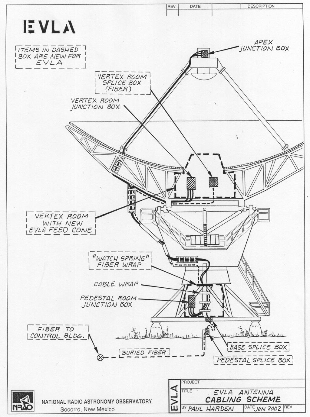
4 Fig. 2 Cabling Scheme VLA Fig. 2 shows the cabling scheme for the existing VLA antennas. All AC power, antenna and F-R motor drive cables, and other signals, are routed from the Pedestal Room to the Vertex Room or Apex via the AZIMUTH CABLE WRAP. This allows the cables to safely twist and flex as the antenna turns in azimuth. The cables also bend at the elevation axis. All cables run between junction boxes, such as from the Pedestal Room Junction Box to the Vertex Room Junction Box. In addition to providing an orderly cable breakout, these junction boxes also contain the gas discharge devices to protect the cabling from antenna lightning strikes. Communications to and from the antennas in the VLA is conducted along the buried waveguide. The waveguide is a single run along each arm, with a waveguide coupler at each pedestal. The waveguide enters the antenna at the bottom and into the Pedestal Room, through the yoke and into the IF/LO B-Rack in the Vertex Room. Rotary joints are provided at the Azimuth and Elevation axis. Fig. 3 Cabling Scheme - EVLA Fig. 3 shows the basic cabling scheme for the EVLA. Most antenna wiring and cabling will remain the same as the VLA. The largest difference will be the removal of the waveguide, and the addition of the fiber optic cables. Similar to the VLA waveguide, the EVLA fiber will enter the antenna into the Pedestal Room via the Pedestal Splice Box and Base Splice Box. The Fiber does not run through the Azimuth Cable Wrap, as fiber is very sensitive to any stretching that might occur. Instead, a special Watch-Spring Fiber wrap will allow the fiber to bend with antenna azimuth movements. From the Watch- Spring, the fiber will run to the Vertex Room along the existing cable trays, terminating into the new Vertex Room Splice Box. A new MCB Rack (not shown in Fig. 3) will provide for the fiber distribution throughout the Vertex Room.
5 Fig. 2
6 Fig. 3
7 Fig. 4 VLA Vertex Room The existing VLA Vertex Room is shown in Fig. 4. It is important to realize that the Vertex Room does not simply hang from the antenna dish, but is rather built inside of and around the existing antenna backup structure struts and members. The position of the existing electronic racks is shown. A-Rack contains the receivers, or front-ends of many of the observing bands. F-Rack contains the receivers and synthesizers for the remaining bands. B-Rack contains the IF/LO electronics, and the interface to the waveguide communications system. Note the waveguide entering the rear of the B-Rack. The Vertex Room Junction Box, Non-Critical and Critical Power Boxes are shown. The HVAC (air conditioning system) is also shown, with the air conditioning unit located outside of the Vertex Room, and the cold air supply ducting going to each electronic rack. Also note the Equipment Hoist and Access hatch outside the Vertex Room door. This is how heavy equipment (receivers, racks, etc.) are lifted from ground level and into the Vertex Room. Fig. 5 EVLA Vertex Room Fig. 5 shows the basic arrangement and geometry of the vertex room for EVLA. The basic Vertex Room structure will not change, as it is an integral part of the antenna backup structure. The VLA feeds will be removed and a new Feed Cone installed for housing and mounting the new feed horns. Note how the new Feed Cone is offset slightly from the octagon of the Vertex Room. This is to allow proper mounting of the feed cone and positioning of the feedhorns and receivers.
8 Fig. 4
9 Fig. 5
10 Fig. 6 EVLA Vertex Room Feeds The lower band feedhorns will be significantly larger than the existing VLA feedhorns in order to accommodate the wider bandwidths of the EVLA, as shown in Fig. 6. Of particular interest is the L-band feed (1-2GHz) with a new total length of over 13 feet. This will require the L-Band Receiver to be located underneath the Vertex Room floor. A hole in the floor, covered with a grate, will be provided to accommodate this. The S-Band (2-4GHz) feed and receiver also consumes considerable space. The C-Band (4-8GHz) Receiver will be mounted near the overhead, at about 6.5 feet high, for normal headroom. These clearances are important for determining the locations of other equipment. The hatched areas in Fig. 7 show the approximate obstructions due to the L and S-Band feeds and receivers. At the time of the Bins and Module PDR, it is not yet known how long the transition pieces on the L and S band waveguides will be. These are the pieces that connect the receivers to the feedhorns, and can vary from about 1 to 3 feet in length. As a result, the exact position of the L and S band receivers may be slightly higher, or lower, than shown.
11 Fig. 6
12 Fig. 7 EVLA Vertex Room Plan 1 Fig. 7 shows one plan for the EVLA Vertex Room layout. Obstructions caused by the L-Band and S-Band feeds and receivers are shown. About 3 feet of clearance must be maintained around these feeds for proper maintenance. The new Vertex Room Splice Box (fiber) and MCB Rack are located near the existing Vertex Room Junction Box. The receivers for the other bands are shown in the dashed boxes to indicate they are located inside the new Feed Cone, and thus above normal head level, but maintenance access from the floor must be provided. The B-Rack will be floor mounted near the door. The UX Converter, servicing the Ku, K, Ka and Q Band receivers, is mounted on the overhead shelf, in close proximity to these receivers, to keep cable lengths at a minimum. LO signals to the receivers, and RF signals from the receivers, pass through selector switches, mounted inside the Feed Cone. The new Sampler Rack is a slightly oversized rack, 32 in. wide, 30 in. deep, but only about 3 feet high. The majority of the signals to the Sampler Rack come from the B-Rack, and will run along cable trays between the two along the Vertex Room walls. Running cable trays directly across the Feed Cone would prevent access to the receivers. All connections to/from the Sampler Rack, including the fiber, is done via connectors on the front of the rack, and thus the rack can be mounted directly against the Vertex Room wall. Not shown is the air conditioning ducting that will run along the Vertex Room wall, from near the Critical Power Box, to the Sampler Rack, MCB Rack and terminating at the B-Rack. Flexible elephant trunk hose will provide cooling air to the UX Converter. All racks must be floor mounted in the EVLA, elevated by about 2 feet, to accommodate the air conditioning plenum underneath. Fig. 8 EVLA Vertex Room Plan 2 Fig. 8 is an alternative EVLA Vertex Room layout. In this case, the B-Rack remains virtually where it is in the VLA antenna, except mounted to the floor. The MCB and Sampler Racks are mounted side-by-side and against the wall, since no back or side access is required. Since both of these racks are halfsized racks, it is felt this may offer better access to the high-band receivers, if that becomes an issue.
13 Fig. 7
14 Fig. 8
FIBER OPTIC HARDWARE STEVE PAULOV
 C H A P T E R 7 FIBER OPTIC HARDWARE STEVE PAULOV The main purpose for hardware is to protect and organize splice and termination points. Hardware can be divided into two categories; indoor and outdoor.
2 Telecommunications Data Center Facility Requirements
 Generic Requirements for Telecommunications Data Center Equipment and Spaces GR-3160-CORE Table of Contents Table of Contents Generic Requirements Notice of Disclaimer..................... iii Preface...........................................
SECTION 5 -- EQUIPMENT LAYOUT & EQUIPMENT ENVIRONMENTS
 SECTION 5 -- EQUIPMENT LAYOUT & EQUIPMENT ENVIRONMENTS CONTENTS PAGE 1. GENERAL... 5-1 1.1. Introduction... 5-1 1.2. Equipment Layout Requirements... 5-1 2. EQUIPMENT FRAMES... 5-2 2.1. Introduction...
Vacuum Maintenance Manual (EXCERPT Tim Benedict)
") 1. Position a ladder, scaffold, or work stand, on the right side of Vacuum Skid where the blower motors are installed. 2. Locate the six (6) vacuum hoses connecting the blower motors to the HEPA housings
1. Position a ladder, scaffold, or work stand, on the right side of Vacuum Skid where the blower motors are installed. 2. Locate the six (6) vacuum hoses connecting the blower motors to the HEPA housings
or
 Infinite possibilities for your data center The F-Series TeraFrame T M Cabinet System The F-Series TeraFrame Cabinet System from Chatsworth Products, Inc. (CPI) provides configurable thermal management
SPOS (Station Point of Sale) 200. SFTP (Station Fare Transaction Processor) 35. CQD (Card Query Device) 35. HCR (Handheld Card Reader) Cradles 120
 200. SFTP (Station Fare Transaction Processor) 35. CQD (Card Query Device) 35. HCR (Handheld Card Reader) Cradles 120") DESIGN GUIDELINES PRESTO INSTALLATION & CONNECTIVITY PAGE 1 of 4 ELECTRICAL CONNECTIVITY AND WIRING Communications Conduits Conduits designated for Presto equipment data wiring shall be clearly identified
DESIGN GUIDELINES PRESTO INSTALLATION & CONNECTIVITY PAGE 1 of 4 ELECTRICAL CONNECTIVITY AND WIRING Communications Conduits Conduits designated for Presto equipment data wiring shall be clearly identified
Newark, Delaware Architectural Engineering Senior Thesis Portfolio
 Telecommunications System Design The represents the advancement of solar design in our world today. The building itself is an example of this. A Headquarters this dedicated to moving into the future should
Moving Containment Inside the Enclosure. Jeff Markle Great Lakes Case & Cabinet
 Moving Containment Inside the Enclosure Presented by Jeff Markle Great Lakes Case & Cabinet Containment Containment : To put constraint upon; to restrain; to confine; to keep within bounds Containment
Quick Start. This document describes how to install the Juniper Networks PTX5000 Packet Transport
 PTX5000 Packet Transport Router Quick Start September 2017 Part Number: 530-066788 Revision 01 This document describes how to install the Juniper Networks PTX5000 Packet Transport Router. Contents Quick
Target Interface / Construction Compliance Inspection Checklist
 TES A. Roads-Service, Lanes Common Items Trails and service roads provide adequate access to buildings for maintenance B. Testing Results-provided to the local government construction representative Data
NATIONAL RADIO ASTRONOMY OBSERVATORY Charlottesville, Virginia VERY LARGE ARRAY PROJECT VLA ELECTRONICS DIVISION MEMO #123
 NATIONAL RADIO ASTRONOMY OBSERVATORY Charlottesville, Virginia VERY LARGE ARRAY PROJECT VLA ELECTRONICS DIVISION MEMO #123 DESIGN SPECIFICATIONS FOR FEED AND RACK SUPPORT STRUCTURE FOR VLA ANTENNA Peter
ANSI/TIA/EIA-568-B Cabling Standard NOTE
 95 ANSI/TIA/EIA-569-A Though the ANSI/TIA/EIA-568-B Standard describes the subsystems of a structured cabling system, the TIA has published a more thorough document called ANSI/TIA/EIA-569-A Commercial
Thermal management. Thermal management
 Thermal management Thermal management Managing thermal loads is a major challenge for all Data Centre operators. Effecting proper control of the thermal environment drives energy consumption and ultimately
Installation Manual. Table of Contents
 Table of Contents Table of Contents... 4-1 4.1 Confirming the Installation Preparations... 4-1 4.2 Installation Flowchart... 4-1 4.3 Mounting the Switch to the Designated Position... 4-2 4.3.1 Mounting
1.8 METER SERIES 1194 ANTENNA SYSTEM
 April 20, 2016 REVISION J ASSEMBLY MANUAL 1.8 METER SERIES 1194 ANTENNA SYSTEM General Dynamics SATCOM Technologies 1700 Cable Drive NE Conover NC 28613 USA Phone 770-689-2040 www.gdsatcom.com 1.8 METER
Wire Communications Design jfm 07. An Inside Look at Outside Plant
 An Inside Look at Outside Plant BICSI Region Meeting 2007 Agenda What is CO-OSP? A close look at the 758-A standard Available Resources What is CO-OSP? Customer Owned Outside Plant Telecommunications infrastructure
PAR+ & MSC+ Controller. Installation Manual
 PAR+ & MSC+ Controller Installation Manual Contents Introduction... 1 System Configuration...1 Parts List and Tools Required for Installation...1 Installation Checklist...1 Mount Controller Pedestal on
E-Series Site Preparation Guide
 E-Series Site Preparation Guide September 2017 215-11797_A0 doccomments@netapp.com Table of Contents 3 Contents Deciding whether to use this guide... 10 Specifications of the model 3040 40U cabinet...
CTO Server and Network Cabinets
 DeltaV Distributed Control System Product Data Sheet January 2018 CTO Server and Network Cabinets CTO Server and Network Cabinet. Delivers standard cabinet with 19 frame construction for your DeltaV networking
EcoTec SP tables and base cabinets
 Shapes and colours Tabletops and furniture surfaces Table superstructures, base cabinets and handles 30 mm panel with replaceable edge, Antistatic, light grey 30 mm panel with impact-resistant edge band
BEAVER TECHNOLOGY SERVICES
 BEAVER TECHNOLOGY SERVICES EMPOWERED E E BY INNOVATION N O N CONTENTS CUSTOM FABRICATION ENGINEERING & CONSULTING SERVICES... 2 TRIPODS & ACCESSORIES... 3 HOISTS, DAVITS, CRANES & ACCESSORIES... 4 PORTABLE
RE Series Rack from Eaton Product Presentation
 RE Series Rack from Eaton Product Presentation AUG 2018 Quick Overview What is Eaton s RE Series Rack Platform? RE Series is an amalgamation of the NR & RE Series with many value-add component enhancements;
Model 90. thermwood. Thermwood CNC Machining Centers. Machine Features Shown
 22017 MADE IN USA 5 Axis Model 90 Thermwood, the industry leader in 5 Axis applications with more five-axis systems in operation than any other company. These 5 Axis CNC routers have become the accepted
RC3KD TriKit RC3000D to ANDREW Trifold Interface Kit. Installation Manual
 RC3KD TriKit RC3000D to ANDREW Trifold Interface Kit Installation Manual 26 March 2008 RESEARCH CONCEPTS INC. 5420 Martindale Shawnee, KS 66218 (913)422-0210 www.researchconcepts.com TABLE OF CONTENTS
2.4Meter Series 1252 Az/El Truss Mount
 4096-356 REVISION E April 21, 2016 Assembly Manual 2.4Meter Series 1252 Az/El Truss Mount General Dynamics 1700 Cable Drive NE Conover NC 28613 USA Phone 770-689-2040 www.gdsatcom.com 2.4M Series 1252
SPI PowerNet requirements for the non-contestable Interface Works at Deer Park Terminal Station
 SPI PowerNet requirements for the non-contestable Interface Works at Deer Park Terminal Station SPI PowerNet Reference: ZD23 Version: 1.1 Issue date: 15 May 2014 Contents 1 Scope... 3 2 Deer Park Terminal
XBR V4 INSTALLATION AND USER GUIDE
 XBR V4 INSTALLATION AND USER GUIDE xbr V4 Installation and User Guide Page 1 of 18 Revision History Dash#/Rev Date Author Description 0.1 04/03/2013 Eric Anderson Initial draft 0.2 04/08/2013 Eric Anderson
MODEL 8000MP LEVEL SENSOR
 1 MODEL 8000MP LEVEL SENSOR INSTRUCTIONS FOR INSTALLATION, OPERATION & MAINTENANCE VISIT OUR WEBSITE SIGMACONTROLS.COM 2 SERIES 8000MP LEVEL SENSOR 1. DESCRIPTION The Model 8000MP Submersible Level Sensor
OMEGA MODULAR PATCH PANEL EMPTY ENCLOSURE
 OMEGA MODULAR PATCH PANEL EMPTY ENCLOSURE The Omega MPP enclosure is based on a 19" frame, with 4 empty module slots for MPP modules. Highly flexible : any mix between twisted pair and optical fiber modules.
NOMAD 4000 Marking System
 Nomad 4000 Marking System General Arrangement SYSTEM OVERVIEW The Telesis NOMAD 4000 marking system permanently prints messages into a variety of materials such as steel, aluminum, and plastic. A hardened
3.0 METER POLAR TRUSS MOUNT
 Revision E June 2, 2016 Assembly Manual 3.0 METER POLAR TRUSS MOUNT 1700 Cable Drive NE Conover NC 28613 USA Phone 770-689-2040 www.gdsatcom.com 3.0 METER POLAR TRUSS MOUNT E Add Conover Address 6/2/16
Strip Till. Ultimate in Strip Till Versatility & Performance. The. Toll Free:
 Strip Till The Ultimate in Strip Till Versatility & Performance Toll Free: 1-800-537-7370 www.remlingermfg.com The Original Remlinger Precision Strip Till (PST) row unit was farmer inspired and tested.
INTRODUCTION CT87E FEATURES AND CONTROLS
 INTRODUCTION The CT87E is a precision instrument used to monitor and record the presence or absence of voltage, light, or sound level such as what would be produced by an operating electric motor or compressor.
Office of the Chief Information Officer Technical Note: IT-960-TN14 Effective: 05/25/2006 Last Revised: 02/17/2012 Issuing Office: OCIO
 Cabling Standards Office of the Chief Information Officer Technical Note: IT-960-TN14 Effective: 05/25/2006 Last Revised: 02/17/2012 Issuing Office: OCIO 1. Purpose CABLING STANDARDS This technical note
FABRICATED PRODUCT RANGE
 FABRICATED PRODUCT RANGE Mobile: +27(0)82 556 0793 Tel / Fax +27(0)11 472 0460 E-Mail: info@kraftig.co.za Website : www.kraftig.co.za Johannesburg / South Africa MOBILE LIFTING GANTRY Chain block and crawler
Network+ Guide to Networks 7 th Edition
 Network+ Guide to Networks 7 th Edition Chapter 4 Structured Cabling and Networking Elements 2016 Cengage Learning. May not be scanned, copied or duplicated, or posted to a publicly accessible website,
MICHIGAN DEPARTMENT OF TRANSPORTATION
 MICHIGAN DEPARTMENT OF TRANSPORTATION SPECIAL PROVISION FOR GROUNDING, BONDING, LIGHTNING PROTECTION AND SURGE PROTECTION FOR INTELLIGENT TRANSPORTATION SYSTEM EQUIPMENT ITS:CLC 1 of 5 APPR:LWB:DBP:07-31-13
Removal and Installation8
 8 Screw Types 8-4 Top Cover Assembly 8-5 Left Hand Cover 8-6 Right Hand Cover 8-10 Front Panel Assembly 8-14 Left Rear Cover 8-15 Right Rear Cover 8-16 Extension Cover (60" Model only) 8-17 Media Lever
HISTORIC AMERICAN ENGINEERING RECORD INDEX TO PHOTOGRAPHS. BLACK AND WHITE PHOTOGRAPHS OF HElM BRIDGE
 HISTORIC AMERICAN ENGINEERING RECORD Cerritos Channel Port oflong Beach Los Angeles County California BLACK AND WHITE PHOTOGRAPHS OF HElM BRIDGE Photographer: Stephen Schafer, September 2010 CA-HEIM-l
IBM. Rack Installation Instructions
 IBM Rack Installation Instructions Review the documentation that comes with your rack cabinet for safety and cabling information. When installing your server in a rack cabinet, consider the following:
Introduction to the CRS Back-to-Back System
 This chapter provides an overview of the CRS Back-to-Back System and describes what is required to interconnect system components. The chapter covers the following topics: System Overview, page 1 Cabling
Rack Installation Instructions
 Rack Installation Instructions Review the documentation that comes with your rack cabinet for safety and cabling information. When installing your server in a rack cabinet, consider the following: v Two
ACSUS-11. Access Cabinet Systems Cabinets & Accessories
 ACSUS-11 Access Cabinet Systems Cabinets & Accessories The cabinet has in the past been considered to be just a metal box, simply providing a mounting structure into which both active and passive equipment
Project Olympus Chassis Mechanical Specification
 Project Olympus Chassis Mechanical Specification Author: Larry Cannon, Senior Mechanical Engineer, Microsoft Revision History Date Description 03/01/2017 Version 0.7 11/01/2017 Version 1.0 Release to
FFI. Advances in Medium and Low Voltage Power Distribution ESS Metron Expo and Technical Seminars. Presented By: Greg Pelster & Robert Schmid
 Advances in Medium and Low Voltage Power Distribution ESS Metron Expo and Technical Seminars Presented By: Greg Pelster & Robert Schmid FFI Ferrie, Franzmann Industries LOW VOLTAGE SWITCHGEAR & LOW VOLTAGE
Project Overview and Status
 Project Overview and Status EVLA Advisory Committee Meeting, March 19-20, 2009 Mark McKinnon EVLA Project Manager Outline Project Goals Organization Staffing Progress since last meeting Budget Contingency
LED Lighting Kit For Elara NanoEdge Fixed Frame. Installation Guide. Attention: Read this guide before assembling your screen.
 LED Lighting Kit For Elara NanoEdge Fixed Frame Installation Guide Attention: Read this guide before assembling your screen. INTRODUCTION GETTING STARTED WARNING - Sharp Edges This product may contain
3.4M & 3.7M Az/El Truss Mount
 REVISION I March 25, 2009 Assembly Manual 3.4M & 3.7M Az/El Truss Mount 1500 Prodelin Drive Newton NC 28658 3.4M & 3.7M Az/El Truss Mount I Revise Logo 3/24/09 RAH H Revised Address 1/10/02 CLT G Redesign
DOCKING STATION SPECIFICATIONS
 ONE PERSON STATION Power Outlets Data Jack Plate Mouse Brackets Front Covers Cable Holes Cable Holes Overview: The Docking Station distributes power, data, and laptop storage to each user. It also offers
Precision Engineered for Positive Results. Manual & Electric Distributor
 Precision Engineered for Positive Results Manual & Electric Distributor Manual Distributor 45 Model Double Distributor Replacement Parts Add new efficiency to your operation with these features & benefits
S1 Access Control Gateway Datasheet
 S1 Access Control Gateway Datasheet Table of contents Information... 2 Technical Specifications... 2 Images... 2 Wiring and Cabling... 3 Option 1: LAN PoE (Preferred Option)... 3 Option 2: WIFI + GPO -
NZQA unit standard version 2 Page 1 of 5
 Page 1 of 5 Title Demonstrate knowledge of installation practices and procedures for telecommunications network equipment Level 3 Credits 10 Purpose This unit standard covers the installation of basic
CONTROLLING ROOFTOP UNIT (RTU) NOISE
 NOISE") HUSHCORE Acoustical Products & Systems Technical Discussion General Information Terminology & Definitions Product Types Treatment Strategies Applications/Uses Industrial Architectural HVAC OEM Environmental
HUSHCORE Acoustical Products & Systems Technical Discussion General Information Terminology & Definitions Product Types Treatment Strategies Applications/Uses Industrial Architectural HVAC OEM Environmental
PRODUCT OVERVIEW. Well Inspection Cameras & Systems. See what you re missing. Proudly made in the U.S.A.
 PRODUCT OVERVIEW Well Inspection Cameras & Systems See what you re missing. Proudly made in the U.S.A. See what you re missing. Aries provides the equipment you need for efficient well inspection to ensure
Centralite CT Moving Laser Patient Positioning System (MRR-1)
") Centralite CT Moving Laser Patient Positioning System (MRR-1) Installation and Setup Manual DIACOR, INC. 2550 DECKER LAKE BLVD., SUITE 26, WEST VALLEY CITY, UTAH 84119 800 342-2679 / 801 467-0050 / 801
Centralite CT Moving Laser Patient Positioning System (MRR-1) Installation and Setup Manual DIACOR, INC. 2550 DECKER LAKE BLVD., SUITE 26, WEST VALLEY CITY, UTAH 84119 800 342-2679 / 801 467-0050 / 801
QuickNetwork QND200 Distribution Panel
 QuickNetwork QND200 Distribution Panel Installation Guide CSQND200V1 10/04 Rev. A Before You Get Started This manual is designed to provide an overview of the installation process and guidelines for installing
Leveraging Fiber Properties to Our Advantage
 Leveraging Fiber Properties to Our Advantage Agenda Fiber Properties Air Blown Fiber Components How It Works Design Considerations We Treat Fiber like Copper We add layers of sheathing and pull it through
Com-Tray. Under Floor. Labor-saving assembly Field proven and tested Superior construction Shipped ready to assemble
 Com-Tray Chalfant, a leading supplier of cable trays and systems for utilities, industrial plants, and commercial service, offers Com-Tray, a unique modular, cost-saving system for routing and protecting
INSTALLATION INSTRUCTIONS
 INSTALLATION FORM# 597A-0711 (Replaces 597A- 1004) UNIT FILTER PLENUM CONTROL MOTOR ECONOMIZER FRESH AIR EXHAUST AIR ROOF CURB FLEXIBLE DUCT CON CEN TRIC DIFFUSER BOX INSTALLATION FLUSH MOUNT SYSTEMS Flush
Cisco CRS 3-Phase AC Power Distribution Unit Installation Guide 2. Cisco CRS 3-Phase AC Power Distribution Unit 2
 Cisco CRS 3-Phase AC Power Distribution Unit Installation Guide Cisco CRS 3-Phase AC Power Distribution Unit Installation Guide 2 Cisco CRS 3-Phase AC Power Distribution Unit 2 Revised: November 18, 2016,
Extended Frequency Range Upgrade Kit (50 GHz to 67 GHz)
") Installation Note Extended Frequency Range Upgrade Kit (50 GHz to 67 GHz) Upgrade Kit Number: E8364-60105 For E8364B/C Microwave Network Analyzers WITHOUT the Configurable Test Set Option (Option 014)
Installation Note Extended Frequency Range Upgrade Kit (50 GHz to 67 GHz) Upgrade Kit Number: E8364-60105 For E8364B/C Microwave Network Analyzers WITHOUT the Configurable Test Set Option (Option 014)
HVAC Project. Comparison of Revit MEP Automatic Duct Sizing and Equal Friction Method Manual Calculations
 346P HVAC Project Comparison of Revit MEP Automatic Duct Sizing and Equal Friction Method Manual Calculations ŀare Name: Date: 10 May 2010 Ben Meinke, Jimmy Principe, Richard Sniff Table of Contents Project
Siemon PON Fiber Cabling Solutions
 Siemon PON Fiber Cabling Solutions WWW.SIEMON.COM 8 Siemon Enterprise PON Fiber Cabling Solution Siemon Enterprise Passive Optical Network (PON) Fiber Cabling Solution improves the modularity, flexibility
REPORT. Energy Efficiency of the San Diego Supercomputer Center and Distributed Data Centers at UCSD. Prepared for:
 REPORT Energy Efficiency of the San Diego Supercomputer Center and Distributed Data Centers at UCSD Prepared for: San Diego Supercomputer Center 10100 John J Hopkins Drive San Diego, CA 92037 May 11, 2009
APC APPLICATION NOTE #146
 #146 Hot Aisle Containment Application Guidelines and Approved Configurations By Kevin Lemke Abstract The Hot Aisle Containment System (HACS) is a modular ceiling panel and door system for use in isolating
RF TARGET AND DECOY SIMULATOR
 RF TARGET AND DECOY SIMULATOR David Wayne dwayne@mi-technologies.com Anil Tellakula, George Cawthon, Jim Langston, Charles Pinson, Makary Awadalla MI Technologies, 1125 Satellite Boulevard, Suite 100,
DATACOM CABINETS SOLUTION GUIDE
 DATACOM CABINETS SOLUTION GUIDE designed to be better. LEGRAND S CABINET OFFERING Legrand cabinets are designed with cable management, airflow management and effortless installation to meet all network
Conceptual-Level Cost Estimate for Point Design of a 30-m Giant Segmented Mirror Telescope (GSMT)
") Conceptual-Level Cost Estimate for Point Design of a 30-m Giant Segmented Mirror Telescope (GSMT) ALL INFORMATION HEREIN IS COPYRIGHTED AND PROVIDED TO NOAO, AURA FOR ITS USE FOR NON-COMMERCIAL RESEARCH
Conceptual-Level Cost Estimate for Point Design of a 30-m Giant Segmented Mirror Telescope (GSMT) ALL INFORMATION HEREIN IS COPYRIGHTED AND PROVIDED TO NOAO, AURA FOR ITS USE FOR NON-COMMERCIAL RESEARCH
FLEXBOX. Installation Guide
 FLEXBOX Installation Guide FLEXBOX 1 Important Safety Instructions WEIGHT LIMIT MAXIMUM WEIGHT 50 LBS. THE STRUCTURE TO WHICH THE BOX IS MOUNTED (CEIL- ING, WALL, TABLE, POLE) MUST BE ABLE TO SUPPORT FIVE
Cabinet Location Plan FIG.01. Cabinet Symbol Key. Air Handler. Air Handler SAN disk storage. SAN disk storage. option B. Not To Scale.
 Cabinet front face - 09 Data Center Storage / Fit-Up Square Feet Square Meters Up Cabinet Symbol Key A Network Row A Network Substation B Server Cabinet A A A A4 A A6 A7 A8 A9 FIG.0 Data Center Square
Section 21. Telecommunication Hardware. BuyLog Catalog 21-1
 Introduction...21-1 Fiber Closure Hardware...21-2 Cable Location Surge Protectors...21-4 Introduction GE has been manufacturing Telecommunication Hardware products for over 20 years and has become a leader
AT&T Virtual Private Network Service (VPN) and AT&T VPN Express
 and AT&T VPN Express") AT&T Virtual Private Network Service (VPN) and AT&T VPN Express Site preparation guide This guide is designed to assist local on-site contacts to understand what you will need to accomplish in preparation
AT&T Virtual Private Network Service (VPN) and AT&T VPN Express Site preparation guide This guide is designed to assist local on-site contacts to understand what you will need to accomplish in preparation
Phoenix Install 4m 12/12
 Phoenix Install 4m 12/12 Place Instrument Change in Progress sign on console Follow instructions for removing the cage bottom Once removed, add or remove the appropriate rocket weights If necessary, follow
EVOTEK ADVANCED CEILING TECHNOLOGY
 EVOTEK ADVANCED CEILING TECHNOLOGY The EVOClean is a modular ceiling system with standard grid dimensions and components.the flexibility of the system is advantageous in the design of clean areas and the
Installation and Operation Instructions I/CO 2, I/CO 2 -VDC, I/CO 2 -T
 Installation and Operation Instructions I/CO 2, I/CO 2 -VDC, I/CO 2 -T READ THESE INSTRUCTIONS BEFORE YOU BEGIN INSTALLATION LOCATION The I/CO 2 transmitter is designed to mount over a standard single
APC APPLICATION NOTE #74
 #74 Configuration of InfraStruXure for Data Centers to Support Dell PowerEdge 1855 Abstract Many companies are making plans to incorporate Dell PowerEdge Blade Servers into their data center applications.
SYSTIMAX Rack and Cabinet Solution
 SYSTIMAX Rack and Cabinet Solution The SYSTIMAX Rack and Cabinet Solution offer is designed for use in telecommunications equipment installations, providing our SYSTIMAX BusinessPartners and customers
Serial ATA Hot Swap Drive Cage Upgrade Kit for: Intel Server Chassis SC5200 Intel Server Chassis SC5250-E
 Serial ATA Hot Swap Drive Cage Upgrade Kit for: Intel Server Chassis SC5200 Intel Server Chassis SC5250-E A Guide for Technically Qualified Assemblers of Intel Identified Subassemblies/Products Order Number:
PRODUCT OVERVIEW. Well Inspection Cameras & Systems. See what you re missing. Proudly made in the U.S.A.
 PRODUCT OVERVIEW Well Inspection Cameras & Systems See what you re missing. Proudly made in the U.S.A. See what you re missing. Aries provides the equipment you need for efficient well inspection to ensure
Plug & Play Universal Low-Loss Systems A LANscape Pretium Solutions Product
 Applications Data Center LAN/SAN Enterprise Building Backbone -to-the-desk Description Plug & Play Universal Systems are preterminated optical fiber cabling systems designed to dramatically improve performance
Table of Contents 1 ABOUT THIS GUIDE CONTACT INFORMATION ANTENNA INSTALLATION... 4
 Table of Contents 1 ABOUT THIS GUIDE... 3 1.1 CONTACT INFORMATION... 3 2 ANTENNA INSTALLATION... 4 2.1 GENERAL INFORMATION... 4 2.2 SPECIFIC MOUNTING EXAMPLES... 5 2.3 CONNECTOR MOISTURE PROTECTION...
Assembly Instructions
 Assembly Instructions Flat Screen Garage End User & IT Computer Cable Management May 2013 nylon zip-tie #2 (for computer wires) rear-access beam door (open) Figure 1 nylon zip-tie #1 (for #1 motor control
Current Control Houses
 Current Control Houses Building Shielding db Type Example 0 Transparent Wood 5 Poor Masonry 10 Moderate Concrete 20 Good Metal Siding 30 Metal All-Metal Current Control Houses Points of Entry Electrical
A note about our online installation instructions:
 A note about our online installation instructions: Most Modern Fan Co. products have been in our assortment for several years or longer. As we continually work to improve product performance and user experience,
Datasheet. Fiber Optic Modular Patch Panel Features
 Features Very high density, supports up to 24 duplex LC adapters (48 fibers), MT-RJ adapters (48 fibers) and simplex SC adapters (24 fibers) in 1U of rack space Pullout drawer enables ease of access to
Design and Installation Challenges: Aisle Containment Systems
 Design and Installation Challenges: Aisle Containment Systems 1 We all know the Benefits of Containment 1. Reduces Total Cost of Data Center Ownership 2. Eliminates hot spots 3. Supports higher heat and
Los Angeles Community College District Design Standards
 LACCD Facilities Design Standards - Structural Cabling and Telecommunications Room Facilities Ver Approved: DTC February 0, 0 LACCD has developed the following Districtwide standard for IT infrastructure
50 Years of Facility Operations or Rebuilding from the inside out
 50 Years of Facility Operations or Rebuilding from the inside out National Optical Astronomy Observatory (NOAO) NORTH Kitt Peak National Observatory and Tucson Headquarters Facility Presented by John Dunlop
System Storage EXP3000 Rack Installation Instructions
 System Storage EXP3000 Rack Installation Instructions Review the documentation that comes with your rack cabinet for safety and cabling information. When you install the IBM System Storage EXP3000 in a
Observatory Automation Project
 Observatory Automation Project Detail Design Review Control of Electric Dome Drive System Grant Matsushige/Steven Bauman Version 1.0 17 May 2010 1. Overview After the preliminary design review, it s been
e550 Wallstation MANUAL
 e550 Wallstation MANUAL 071014 The Enovate Medical e550 Wallstation was designed to set a new standard in quality. Enovate Medical s goal is to provide a wallstation ready for years of use and backed
400A Fiber Optic Interface Unit Space-Saving Enclosure Provides Easy Access to Connectors, plus Increased Security
 400A Fiber Optic Interface Unit Space-Saving Enclosure Provides Easy Access to Connectors, plus Increased Security Applications 400 A1 LIU 400 A2 LIU Because of its security features and flexible design,
BENCHMIKE PRO NEW. The Industry s leading off-line ID/OD/Wall measurement system
 BENCHMIKE PRO NEW The Industry s leading off-line ID/OD/Wall measurement system Industry s leading sample inspection system Measure manufactured cut samples fast and with the highest accuracy in the industry
Nov.08. Chinaracks Shanghai Technical Communication Company PRODUCT SPEC: Wide body Server Cabinet - Server Rack - Cabnet 42U
 PRODUCT SPEC: Wide body Server Cabinet - Server Rack - Cabnet 42U Nov.08 2012 http://www.globalsources.com/chinaracks.co www.chinaracks.net Mail: devis@chinaracks.net Chinaracks Shanghai Technical Communication
Cutting Cabling Costs By Mike Martin
 Data Center Solutions White 01 Cutting Cabling Costs By Mike Martin 603.474.2626 info@martinenclosures.com www.martinenclosures.com Are your cabling costs soaring out of control? Important cable management
APES-14 HD-6500 & HD-7000 Version Operator s Training Manual
 APES-14 HD-6500 & HD-7000 Version Operator s Training Manual Issue A1 09/03 PDI Part # 900600 Performance Design Inc. 2350 East Braniff St. Boise Idaho 83716 This manual contains very important safety
Properly Placing the Wireless Control Pad Coordinator/Repeater
 Properly Placing the Wireless Control Pad Coordinator/Repeater A new addition to NuVo s product lineup for 2009 is the Wireless Control Pad. The Wireless Control Pad provides customers the ability to control
15U Wall-Mount Server Rack Cabinet - 20 in. Deep - Hinged
 15U Wall-Mount Server Rack Cabinet - 20 in. Deep - Hinged Product ID: RK1520WALHM This 15U server or network rack cabinet lets you mount your EIA-310 compliant equipment to the wall, in a secure enclosure
lighting, electrics & communications
 lighting, electrics & communications P RO D U C T M A P...................................2 9 0 289 L I G H T I N G, E L E C T R I C S & C O M M U N I C AT I O N S O V E RV I E W....2 9 4 L I G H T I N
2.4 Meter Series 1253 Polar Truss Mount
 4096-479 July 7, 2009 Revision E ASSEMBLY MANUAL 2.4 Meter Series 1253 Polar Truss Mount General Dynamics 1500 PRODELIN DRIVE NEWTON, NC 28658 USA PH. 828-464-4141 www.gdsatcom.com 2.4 Meter Series 1253