Rotating Moving Boundary Analysis Using ANSYS 5.7
|
|
|
- Miles Glenn
- 6 years ago
- Views:
Transcription
1 Abstract Rotating Moving Boundary Analysis Using ANSYS 5.7 Qin Yin Fan CYBERNET SYSTEMS CO., LTD. Rich Lange ANSYS Inc. As subroutines in commercial software, APDL (ANSYS Parametric Design Language) provides a strong tool for software development. APDL is not only merely a language, but a language based on the applications of ANSYS. In such an environment the software development can be done based not only a language and library, but also on some applications. With ANSYS/FLOTRAN 5.7 enhanced with ALE and Interpolation, a rotating moving boundary calculation is designed with APDL. The APDL flow chart will be listed for general reference of rotating moving boundary analysis. The new approach is validated in 2 models: the flow around a rotating square and the flow around a rotating fan. Introduction Some examples show that interpolation of ANSYS version 5.7 can be used for data transformation of steady state compressible flow simulation to saving CPU time. In this case, the coarse mesh is used to get a result that is late transferred to a finer new mesh as initial condition for further analysis [1]. In another way, during the transient simulation of flow with moving boundary, the computational mesh may undergo considerably distortion using ALE (Arbitrary Lagrangian Eulerian) [2] Method. A distorted mesh with large aspect ratio, small mesh angel, etc. provides poor reference system and becomes unsuitable for further analysis. When this occurs, a more suitable mesh is desirable to be generated and all solution variables from the old distorted mesh are desirable to be transferred to the new one. This is known as interpolation or rezoning. In ANSYS version 5.7, there are some examples of ALE such as torsion oscillation and squeeze film [1]. All the rotating movement of boundary is less than 45 degree. In this paper, with ALE and Interpolation, a rotating moving boundary calculation approach is designed with APDL and the approach is validated in 2 models: the flow around a rotating square and the flow around a rotating fan. As subroutines in commercial software, APDL (ANSYS Parametric Design Language) provides a strong tool for software development. APDL is not only merely a language, but a language based on the applications of ANSYS. In such an environment the software development can be done based not only a language and library, but also on some applications. Rotating movement calculations are a kind of development using APDL based on applications of ALE and interpolation of ANSYS5.7. At last, the improvement requirements about interpolation accuracy, result file arrangement, tabular boundary conditions are listed. Models And Boundary Conditions Fan model and boundary conditions For ALE rotating boundary simulation, at least two mesh patterns must be prepared for interpolation. According to the model shape, three, four or more patterns are necessary. In figure 1, the simplest example of rotating fan is shown. The length of the domain is 20 mm, the breadth of inlet is 8 mm. The center of fan is mm away from the inlet and is at the centerline of the domain in y direction. The radius of circle area is 2 mm. There are all 8563 nodes and 8140 elements for the whole domain. There are 6286 nodes and 5869 elements in


2 circle areas. In the circle area, the movement of nodes is considered in ALE calculation. Out of the circle area, the nodes are fixed. Figure 1 - the domain of calculation. Detail of blades is shown in figure 2. In the model, there are 32 rotating blades in the circle area and they rotate around the center of the circle area. The length of blades is 0.4 mm and the breadth of blades is 0.04 mm. The outside of blades is 1.8 mm to the circle center and the inner side of blades is 1.4 mm to the circle center. The inlet of flow is at left side of the domain and the inlet velocity is 20 mm/s. Outlet is on the right side defined as zero pressure. The above and bottom of the domain are fixed wall with zero velocity in both x and y directions. In figure 3, the starting mesh is shown. With defined moving boundary conditions and method of ALE, the rotating blades move to the position in figure 4. Forty time steps are calculated from the position in figure 3 to the position in figure 4. The size of time step is s. Namely, 0.08 s elapses when blades rotate degree. Blades rotate at an angular velocity about RPM and the outside of blades moves at a tangent velocity about mm/s. In this case, fluid is uncompressible, Reynolds Number is 11.3 and laminar flow is defined. Figure 2 - Left: the detail of domain. Right: the detail of some blades.


3 Figure 3 - Left: the first mesh pattern for starting. Right: the blade position. Figure 4 - Left: the first mesh pattern before interpolation. Right: the blade position. When blades move to the position in figure 4, the mesh cannot be distorted anymore. Especially the aspect ration and angle of meshes in the forward direction become very bad. That means a more suitable mesh is desirable to be generated and all solution variables from the old distorted mesh are desirable to be transformed to the new one. As the reason of above, for interpolation, a new domain is made as in Fig. 5. The blades in figure 5 are all in the same position as in figure 4, but the domain is divided with different meshes compared with figure 4. The result is interpolated (or transferred) from the old mesh in figure 4 to the new mesh in figure 5. The old mesh in figure 4 is named as the first mesh pattern before interpolation. The new mesh in figure 5 is named the second mesh pattern for continuing. After the same time steps, blades move from the position in figure 5 to the position in figure 6. Figure 5 - Left: the second mesh pattern for continuing. Right: the blade position.


4 At last, the second mesh pattern in figure 6 constructs the same domain as the pattern in figure 3, but in a different mesh pattern. So, the above process can be repeated between figure 6 and figure times of interpolation are necessary for one rotation of fan. And the process is repeated again and again until the end time of calculation is arrived. Figure 6 - Left: the 2nd mesh pattern before interpolation. Right: the blade position The moving velocity of nodes on lines around every blade is defined to keep the good shape of the meshes during the calculation. There are all together 128 lines for all 32 blades. Rotating square cylinder model and boundary conditions For a rotating square cylinder, the 2D domain is shown in figure 7. The domain length in x direction is 20 m. The inlet breadth in y direction is 8 m. The center of rotating square is m away from the inlet and at the centerline of the domain in y direction. The radius of circle area is 2 m and the size of the square is 1.2 m. There are all 1771 nodes and 1669 elements for the whole domain. There are 576 nodes and 512 elements in areas between square and circle. The movement of nodes in the area between square and circle is considered in ALE calculation. There are 16 areas between square and circle. That let the 16 times interpolations be possible for one rotation of the square. Figure 7 - Domain of rotating square cylinder Inlet is at left side of the domain and is defined as 1.0 m/s. Outlet is at right side of the domain and is defined as zero pressure. The upper and lower boundaries are defined as no-slip wall. The fluid is uncompressible air and the density and viscosity are constant at 293 K. and one atmosphere pressure. So the Reynolds Number is and turbulent model of standard k-ε is used.
 is interpolated to the new mesh in figure 8(2-1) and the calculation then continues.")

 and 8(1-2).")
 (1-2) (2-1) (2-2) (3-1) (3-2) (4-1) (4-2) Figure 8 - (a) Left: (n-1) original shape of the nth mesh patterns.")


5 Four mesh patterns are necessary in this calculation as shown in figure 8. When the square rotates from the position of figure 8(1-1) to 8(1-2), e.g degrees, 200 time steps, the result of figure 8(1-2) is interpolated to the new mesh in figure 8(2-1) and the calculation then continues. These are repeated from pattern 2 to 3 and then from pattern 3 to 4. At last, when the square rotates 90 degree, the next necessary pattern becomes pattern one. With these four patterns, the calculation can go to the end time of the calculation. Time step size is s and there are 200 time steps between one interpolation such as that between figure 8(1-1) and 8(1-2). The four edges of square are defined as moving boundaries that are rotating at a rotational magnitude of 37.5 RPM. (1-1) (1-2) (2-1) (2-2) (3-1) (3-2) (4-1) (4-2) Figure 8 - (a) Left: (n-1) original shape of the nth mesh patterns. Right: (n-2) the shape of the nth mesh pattern after 10 time steps. (n=1,2,3,4). The moving velocity of some nodes is defined to keep the good shape of the meshes during the calculation. These nodes position radiation lines around the square of sections of blades. There are four radiation lines around every the square in Fig. 3. Analysis Results & Discussion The results of fan model The results of rotating fan are plotted in Fig. 9 and 10. The wall time of every picture is noted at the above-left corner respectively. As the rotating velocity is much slower than the inlet velocity, the rotation less affects the flow. No complex flow pattern in the area near the fan or after the fan blades can be observed. In another way, because the incompressible flow becomes steady state at once after the calculation, little change can be seen after 0.08 s too.

6 Figure 9 - Pressure variation of domain to time of 0.08 s intervals

7 Figure 10 - The velocity distribution of the domain at different time The results of rotating square cylinder The results of rotating square cylinder are shown in figure 11 and 12. In Fig.11, the velocity vectors at time 0.4 s, 0.5, 0.6, 0.7, , 1.0, 1.5, 2.0 and 2.5 s are plotted. The time is noted at the above-left corner of the every figure respectively. As the rotating velocity is faster than the inlet velocity, the rotation of square affects the flow strongly. A very complex flow pattern in the area near the square is observed.
8 Figure 11 - Velocity vectors of flow around the square cylinder at time 04 to 2.5 s.


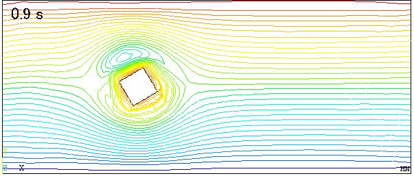
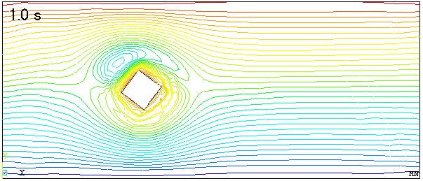
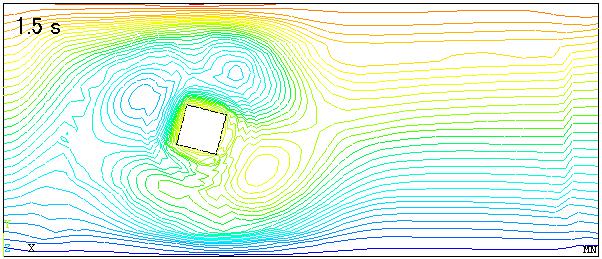
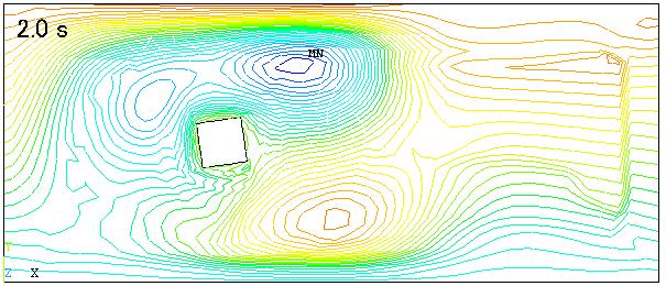
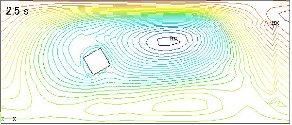
9 Figure 12 - Stream functions of flow around the square cylinder at time 04 to 2.5 s.

10 The stream functions of flow are shown in figure 12. They are at the same time as velocity vectors shown in figure 11. When the time increases the affected area become bigger and bigger. The corner nodes of the rotating square have the biggest radius to the rotating center. The tangent velocity of the four nodes should be the biggest velocity in the four moving edges of the square. The value can be estimated using the rotating angle velocity and it is about m/s. But near the square, the maximum velocity about 10 m/s is observed and increases to passing time. This can be considered as 1) an accumulation of error of a coarse mesh, 2) or the affection of an unsuitable turbulent model, 3) or the accumulation of error of many times interpolation. Until 2.5 s, 25 times of interpolation have been executed. After investigation about interpolation, the movement energy may become smaller than before interpolation. In figure 13, the above is the result before interpolation and the bottom is the result after interpolation. After interpolation the maximum velocity always become smaller than before as at the time 0.9 s in figure 13. So, the third reason can be put out of here. The previous two reasons are planned to investigate in detail. Figure 13 - Comparison of velocity vector distributions before and after interpolation at 0.8s Although, the above two models are validated, very complex manipulation must prepared for every calculation. At first several pattern of mashes must be made. Second, the interpolation time is not very easy to determine. Third, the accumulated error can not be avoided and the CPU time is wasted during many times of interpolations. Especially for 3D calculations, the above listed problems will become more rigid. Even, they may be difficulties that could not be solved for many models. Quite the contrary, the Shear-Slip Mesh Update Method [3] can be used in ANSYS very easily. If the Deformable-Spatial-Domain/Stabilized Space Time (DSD/SST) formulation [3] can be introduced into ANSYS. ANSYS can become a strong tool for moving boundary condition calculations.
11 Conclusion Rotating movement calculation has been verified to show the development possibility using APDL basing on applications of ALE and interpolation of ANSYS5.7. The models of rotating square and 32 blade rotating fan validate the method. In this paper, the authors have only enough time to time to put the method in order. Further investigations are scheduled about the result verification of flow around one rotating cylinder and the calculation of flow around two counter-rotating square cylinders. Although both examples are 2D models, the method can be considered as a general useful method for 3D rotating calculation too. Surely the following several matters should be improved to let the method can be much easily to use. 1) The pre processor should be improved to make the mesh patterns easily that can be interpolated to each other. 2) The accuracy of interpolating should be improved for transient ALE application. 3) The post processor should be improved to show the continuous result such as rotating calculation. 4) Other method such as the shear-slip mesh update method and the Deformable-Spatial-Domain/Stabilized Space Time (DSD/SST) formulation (3) should be introduced into ANSYS. References 1) New Features 5.7 Training Manual, ANSYS.inc August 15, ) C.W. Hirt, A.A. Amsden, and H.K. Cook, An arbitrary Lagrangian Eulerian computing method for all flow speeds. J. Comput. Phys. 14(1974) ) M. Behr and T. Tezduyar, The Shear-Slip Mesh Update Method, Comput. Methods Appl. Mech. Engrg. 174(1999)
Coupled Analysis of FSI
 Coupled Analysis of FSI Qin Yin Fan Oct. 11, 2008 Important Key Words Fluid Structure Interface = FSI Computational Fluid Dynamics = CFD Pressure Displacement Analysis = PDA Thermal Stress Analysis = TSA
Verification and Validation of Turbulent Flow around a Clark-Y Airfoil
 Verification and Validation of Turbulent Flow around a Clark-Y Airfoil 1. Purpose 58:160 Intermediate Mechanics of Fluids CFD LAB 2 By Tao Xing and Fred Stern IIHR-Hydroscience & Engineering The University
Simulation of Turbulent Flow in an Asymmetric Diffuser
 Simulation of Turbulent Flow in an Asymmetric Diffuser 1. Purpose 58:160 Intermediate Mechanics of Fluids CFD LAB 3 By Tao Xing and Fred Stern IIHR-Hydroscience & Engineering The University of Iowa C.
Strömningslära Fluid Dynamics. Computer laboratories using COMSOL v4.4
 UMEÅ UNIVERSITY Department of Physics Claude Dion Olexii Iukhymenko May 15, 2015 Strömningslära Fluid Dynamics (5FY144) Computer laboratories using COMSOL v4.4!! Report requirements Computer labs must
ANSYS AIM Tutorial Steady Flow Past a Cylinder
 ANSYS AIM Tutorial Steady Flow Past a Cylinder Author(s): Sebastian Vecchi, ANSYS Created using ANSYS AIM 18.1 Problem Specification Pre-Analysis & Start Up Solution Domain Boundary Conditions Start-Up
Introduction to ANSYS CFX
 Workshop 03 Fluid flow around the NACA0012 Airfoil 16.0 Release Introduction to ANSYS CFX 2015 ANSYS, Inc. March 13, 2015 1 Release 16.0 Workshop Description: The flow simulated is an external aerodynamics
Using a Single Rotating Reference Frame
 Tutorial 9. Using a Single Rotating Reference Frame Introduction This tutorial considers the flow within a 2D, axisymmetric, co-rotating disk cavity system. Understanding the behavior of such flows is
Computational Study of Laminar Flowfield around a Square Cylinder using Ansys Fluent
 MEGR 7090-003, Computational Fluid Dynamics :1 7 Spring 2015 Computational Study of Laminar Flowfield around a Square Cylinder using Ansys Fluent Rahul R Upadhyay Master of Science, Dept of Mechanical
ANSYS AIM Tutorial Turbulent Flow Over a Backward Facing Step
 ANSYS AIM Tutorial Turbulent Flow Over a Backward Facing Step Author(s): Sebastian Vecchi, ANSYS Created using ANSYS AIM 18.1 Problem Specification Pre-Analysis & Start Up Governing Equation Start-Up Geometry
CFD Simulation of a dry Scroll Vacuum Pump including Leakage Flows
 CFD Simulation of a dry Scroll Vacuum Pump including Leakage Flows Jan Hesse, Rainer Andres CFX Berlin Software GmbH, Berlin, Germany 1 Introduction Numerical simulation results of a dry scroll vacuum
CFD Analysis of 2-D Unsteady Flow Past a Square Cylinder at an Angle of Incidence
 CFD Analysis of 2-D Unsteady Flow Past a Square Cylinder at an Angle of Incidence Kavya H.P, Banjara Kotresha 2, Kishan Naik 3 Dept. of Studies in Mechanical Engineering, University BDT College of Engineering,
RBF Morph An Add-on Module for Mesh Morphing in ANSYS Fluent
 RBF Morph An Add-on Module for Mesh Morphing in ANSYS Fluent Gilles Eggenspieler Senior Product Manager 1 Morphing & Smoothing A mesh morpher is a tool capable of performing mesh modifications in order
This tutorial illustrates how to set up and solve a problem involving solidification. This tutorial will demonstrate how to do the following:
 Tutorial 22. Modeling Solidification Introduction This tutorial illustrates how to set up and solve a problem involving solidification. This tutorial will demonstrate how to do the following: Define a
Calculate a solution using the pressure-based coupled solver.
 Tutorial 19. Modeling Cavitation Introduction This tutorial examines the pressure-driven cavitating flow of water through a sharpedged orifice. This is a typical configuration in fuel injectors, and brings
The viscous forces on the cylinder are proportional to the gradient of the velocity field at the
 Fluid Dynamics Models : Flow Past a Cylinder Flow Past a Cylinder Introduction The flow of fluid behind a blunt body such as an automobile is difficult to compute due to the unsteady flows. The wake behind
Development of an Integrated Computational Simulation Method for Fluid Driven Structure Movement and Acoustics
 Development of an Integrated Computational Simulation Method for Fluid Driven Structure Movement and Acoustics I. Pantle Fachgebiet Strömungsmaschinen Karlsruher Institut für Technologie KIT Motivation
Design Optimization of a Weather Radar Antenna using Finite Element Analysis (FEA) and Computational Fluid Dynamics (CFD)
 and Computational Fluid Dynamics (CFD)") Design Optimization of a Weather Radar Antenna using Finite Element Analysis (FEA) and Computational Fluid Dynamics (CFD) Fernando Prevedello Regis Ataídes Nícolas Spogis Wagner Ortega Guedes Fabiano Armellini
Design Optimization of a Weather Radar Antenna using Finite Element Analysis (FEA) and Computational Fluid Dynamics (CFD) Fernando Prevedello Regis Ataídes Nícolas Spogis Wagner Ortega Guedes Fabiano Armellini
Verification of Laminar and Validation of Turbulent Pipe Flows
 1 Verification of Laminar and Validation of Turbulent Pipe Flows 1. Purpose ME:5160 Intermediate Mechanics of Fluids CFD LAB 1 (ANSYS 18.1; Last Updated: Aug. 1, 2017) By Timur Dogan, Michael Conger, Dong-Hwan
MASSACHUSETTS INSTITUTE OF TECHNOLOGY. Analyzing wind flow around the square plate using ADINA Project. Ankur Bajoria
 MASSACHUSETTS INSTITUTE OF TECHNOLOGY Analyzing wind flow around the square plate using ADINA 2.094 - Project Ankur Bajoria May 1, 2008 Acknowledgement I would like to thank ADINA R & D, Inc for the full
Simulation of Turbulent Flow over the Ahmed Body
 Simulation of Turbulent Flow over the Ahmed Body 58:160 Intermediate Mechanics of Fluids CFD LAB 4 By Timur K. Dogan, Michael Conger, Maysam Mousaviraad, and Fred Stern IIHR-Hydroscience & Engineering
Simulation of Turbulent Flow around an Airfoil
 1. Purpose Simulation of Turbulent Flow around an Airfoil ENGR:2510 Mechanics of Fluids and Transfer Processes CFD Lab 2 (ANSYS 17.1; Last Updated: Nov. 7, 2016) By Timur Dogan, Michael Conger, Andrew
Ashwin Shridhar et al. Int. Journal of Engineering Research and Applications ISSN : , Vol. 5, Issue 6, ( Part - 5) June 2015, pp.
 June 2015, pp.") RESEARCH ARTICLE OPEN ACCESS Conjugate Heat transfer Analysis of helical fins with airfoil crosssection and its comparison with existing circular fin design for air cooled engines employing constant rectangular
RESEARCH ARTICLE OPEN ACCESS Conjugate Heat transfer Analysis of helical fins with airfoil crosssection and its comparison with existing circular fin design for air cooled engines employing constant rectangular
Non-Newtonian Transitional Flow in an Eccentric Annulus
 Tutorial 8. Non-Newtonian Transitional Flow in an Eccentric Annulus Introduction The purpose of this tutorial is to illustrate the setup and solution of a 3D, turbulent flow of a non-newtonian fluid. Turbulent
Solved with COMSOL Multiphysics 4.0a. COPYRIGHT 2010 COMSOL AB.
 Journal Bearing Introduction Journal bearings are used to carry radial loads, for example, to support a rotating shaft. A simple journal bearing consists of two rigid cylinders. The outer cylinder (bearing)
Aerodynamic Study of a Realistic Car W. TOUGERON
 Aerodynamic Study of a Realistic Car W. TOUGERON Tougeron CFD Engineer 2016 Abstract This document presents an aerodynamic CFD study of a realistic car geometry. The aim is to demonstrate the efficiency
ANSYS AIM Tutorial Compressible Flow in a Nozzle
 ANSYS AIM Tutorial Compressible Flow in a Nozzle Author(s): Sebastian Vecchi Created using ANSYS AIM 18.1 Problem Specification Pre-Analysis & Start Up Pre-Analysis Start-Up Geometry Import Geometry Mesh
Speed and Accuracy of CFD: Achieving Both Successfully ANSYS UK S.A.Silvester
 Speed and Accuracy of CFD: Achieving Both Successfully ANSYS UK S.A.Silvester 2010 ANSYS, Inc. All rights reserved. 1 ANSYS, Inc. Proprietary Content ANSYS CFD Introduction ANSYS, the company Simulation
Estimating Vertical Drag on Helicopter Fuselage during Hovering
 Estimating Vertical Drag on Helicopter Fuselage during Hovering A. A. Wahab * and M.Hafiz Ismail ** Aeronautical & Automotive Dept., Faculty of Mechanical Engineering, Universiti Teknologi Malaysia, 81310
ANSYS AIM Tutorial Fluid Flow Through a Transition Duct
 ANSYS AIM Tutorial Fluid Flow Through a Transition Duct Author(s): Sebastian Vecchi, ANSYS Created using ANSYS AIM 18.1 Problem Specification Start Up Geometry Import Geometry Extracting Volume Suppress
International Power, Electronics and Materials Engineering Conference (IPEMEC 2015)
") International Power, Electronics and Materials Engineering Conference (IPEMEC 2015) Numerical Simulation of the Influence of Intake Grille Shape on the Aerodynamic Performance of a Passenger Car Longwei
International Power, Electronics and Materials Engineering Conference (IPEMEC 2015) Numerical Simulation of the Influence of Intake Grille Shape on the Aerodynamic Performance of a Passenger Car Longwei
Verification and Validation of Turbulent Flow around a Clark-Y Airfoil
 1 Verification and Validation of Turbulent Flow around a Clark-Y Airfoil 1. Purpose ME:5160 Intermediate Mechanics of Fluids CFD LAB 2 (ANSYS 19.1; Last Updated: Aug. 7, 2018) By Timur Dogan, Michael Conger,
McNair Scholars Research Journal
 McNair Scholars Research Journal Volume 2 Article 1 2015 Benchmarking of Computational Models against Experimental Data for Velocity Profile Effects on CFD Analysis of Adiabatic Film-Cooling Effectiveness
A B C D E. Settings Choose height, H, free stream velocity, U, and fluid (dynamic viscosity and density ) so that: Reynolds number
 so that: Reynolds number") Individual task Objective To derive the drag coefficient for a 2D object, defined as where D (N/m) is the aerodynamic drag force (per unit length in the third direction) acting on the object. The object
Individual task Objective To derive the drag coefficient for a 2D object, defined as where D (N/m) is the aerodynamic drag force (per unit length in the third direction) acting on the object. The object
FLUID MECHANICS TESTS
 FLUID MECHANICS TESTS Attention: there might be more correct answers to the questions. Chapter 1: Kinematics and the continuity equation T.2.1.1A flow is steady if a, the velocity direction of a fluid
ANSYS FLUENT. Airfoil Analysis and Tutorial
 ANSYS FLUENT Airfoil Analysis and Tutorial ENGR083: Fluid Mechanics II Terry Yu 5/11/2017 Abstract The NACA 0012 airfoil was one of the earliest airfoils created. Its mathematically simple shape and age
Express Introductory Training in ANSYS Fluent Workshop 06 Using Moving Reference Frames and Sliding Meshes
 Express Introductory Training in ANSYS Fluent Workshop 06 Using Moving Reference Frames and Sliding Meshes Dimitrios Sofialidis Technical Manager, SimTec Ltd. Mechanical Engineer, PhD PRACE Autumn School
Simulation and Validation of Turbulent Pipe Flows
 Simulation and Validation of Turbulent Pipe Flows ENGR:2510 Mechanics of Fluids and Transport Processes CFD LAB 1 (ANSYS 17.1; Last Updated: Oct. 10, 2016) By Timur Dogan, Michael Conger, Dong-Hwan Kim,
VERIFICATION OF CAMPBELL DIAGRAMS USING ANSYS - LINFLOW AND FUNDAMENTALS OF AEROELASTIC ANALYSES
 VERIFICATION OF CAMPBELL DIAGRAMS USING ANSYS - LINFLOW AND FUNDAMENTALS OF AEROELASTIC ANALYSES Olcay ÇİÇEKDAĞ - Aeronautics Eng, MSc., FİGES A.Ş. CONTENTS 1) AIM 2) STRUCTURAL VIBRATION ANALYSES 2.1)
Influence of mesh quality and density on numerical calculation of heat exchanger with undulation in herringbone pattern
 Influence of mesh quality and density on numerical calculation of heat exchanger with undulation in herringbone pattern Václav Dvořák, Jan Novosád Abstract Research of devices for heat recovery is currently
cuibm A GPU Accelerated Immersed Boundary Method
 cuibm A GPU Accelerated Immersed Boundary Method S. K. Layton, A. Krishnan and L. A. Barba Corresponding author: labarba@bu.edu Department of Mechanical Engineering, Boston University, Boston, MA, 225,
ANSYS AIM Tutorial Flow over an Ahmed Body
 Author(s): Sebastian Vecchi Created using ANSYS AIM 18.1 ANSYS AIM Tutorial Flow over an Ahmed Body Problem Specification Start Up Geometry Import Geometry Enclose Suppress Mesh Set Mesh Controls Generate
Using Multiple Rotating Reference Frames
 Tutorial 10. Using Multiple Rotating Reference Frames Introduction Many engineering problems involve rotating flow domains. One example is the centrifugal blower unit that is typically used in automotive
Drag and Lift Validation of Wing Profiles
 Drag and Lift Validation of Wing Profiles STAR European Conference 2010 London By: Dr Martin van Staden Aerotherm Computational Dynamics 14th IAHR Conference December 2009 Outline of Presentation Background
Backward facing step Homework. Department of Fluid Mechanics. For Personal Use. Budapest University of Technology and Economics. Budapest, 2010 autumn
 Backward facing step Homework Department of Fluid Mechanics Budapest University of Technology and Economics Budapest, 2010 autumn Updated: October 26, 2010 CONTENTS i Contents 1 Introduction 1 2 The problem
Simulation of Laminar Pipe Flows
 Simulation of Laminar Pipe Flows 57:020 Mechanics of Fluids and Transport Processes CFD PRELAB 1 By Timur Dogan, Michael Conger, Maysam Mousaviraad, Tao Xing and Fred Stern IIHR-Hydroscience & Engineering
SIMULATION OF PROPELLER-SHIP HULL INTERACTION USING AN INTEGRATED VLM/RANSE SOLVER MODELING.
 SIMULATION OF PROPELLER-SHIP HULL INTERACTION USING AN INTEGRATED VLM/RANSE SOLVER MODELING. M.N.Senthil Prakash, Department of Ocean Engineering, IIT Madras, India V. Anantha Subramanian Department of
Eulerian Techniques for Fluid-Structure Interactions - Part II: Applications
 Published in Lecture Notes in Computational Science and Engineering Vol. 103, Proceedings of ENUMATH 2013, pp. 755-762, Springer, 2014 Eulerian Techniques for Fluid-Structure Interactions - Part II: Applications
Simulation of Turbulent Flow over the Ahmed Body
 1 Simulation of Turbulent Flow over the Ahmed Body ME:5160 Intermediate Mechanics of Fluids CFD LAB 4 (ANSYS 18.1; Last Updated: Aug. 18, 2016) By Timur Dogan, Michael Conger, Dong-Hwan Kim, Maysam Mousaviraad,
Modeling Unsteady Compressible Flow
 Tutorial 4. Modeling Unsteady Compressible Flow Introduction In this tutorial, FLUENT s density-based implicit solver is used to predict the timedependent flow through a two-dimensional nozzle. As an initial
Possibility of Implicit LES for Two-Dimensional Incompressible Lid-Driven Cavity Flow Based on COMSOL Multiphysics
 Possibility of Implicit LES for Two-Dimensional Incompressible Lid-Driven Cavity Flow Based on COMSOL Multiphysics Masanori Hashiguchi 1 1 Keisoku Engineering System Co., Ltd. 1-9-5 Uchikanda, Chiyoda-ku,
LS-DYNA 980 : Recent Developments, Application Areas and Validation Process of the Incompressible fluid solver (ICFD) in LS-DYNA.
 in LS-DYNA.") 12 th International LS-DYNA Users Conference FSI/ALE(1) LS-DYNA 980 : Recent Developments, Application Areas and Validation Process of the Incompressible fluid solver (ICFD) in LS-DYNA Part 1 Facundo Del
12 th International LS-DYNA Users Conference FSI/ALE(1) LS-DYNA 980 : Recent Developments, Application Areas and Validation Process of the Incompressible fluid solver (ICFD) in LS-DYNA Part 1 Facundo Del
Express Introductory Training in ANSYS Fluent Workshop 08 Vortex Shedding
 Express Introductory Training in ANSYS Fluent Workshop 08 Vortex Shedding Dimitrios Sofialidis Technical Manager, SimTec Ltd. Mechanical Engineer, PhD PRACE Autumn School 2013 - Industry Oriented HPC Simulations,
Simulation of Turbulent Flow around an Airfoil
 Simulation of Turbulent Flow around an Airfoil ENGR:2510 Mechanics of Fluids and Transfer Processes CFD Pre-Lab 2 (ANSYS 17.1; Last Updated: Nov. 7, 2016) By Timur Dogan, Michael Conger, Andrew Opyd, Dong-Hwan
APPLIED COMPUTATIONAL FLUID DYNAMICS-PROJECT-3
 APPLIED COMPUTATIONAL FLUID DYNAMICS-PROJECT-3 BY SAI CHAITANYA MANGAVELLI Common Setup Data: 1) Mesh Proximity and Curvature with Refinement of 2. 2) Double Precision and second order for methods in Solver.
THE APPLICATION OF AN ATMOSPHERIC BOUNDARY LAYER TO EVALUATE TRUCK AERODYNAMICS IN CFD
 THE APPLICATION OF AN ATMOSPHERIC BOUNDARY LAYER TO EVALUATE TRUCK AERODYNAMICS IN CFD A SOLUTION FOR A REAL-WORLD ENGINEERING PROBLEM Ir. Niek van Dijk DAF Trucks N.V. CONTENTS Scope & Background Theory:
Advanced Mesh Update Techniques for Problems Involving Large Displacements
 WCCM V Fifth World Congress on Computational Mechanics July 7,, Vienna, Austria Eds.: H.A. Mang, F.G. Rammerstorfer, J. Eberhardsteiner Advanced Mesh Update Techniques for Problems Involving Large Displacements
Driven Cavity Example
 BMAppendixI.qxd 11/14/12 6:55 PM Page I-1 I CFD Driven Cavity Example I.1 Problem One of the classic benchmarks in CFD is the driven cavity problem. Consider steady, incompressible, viscous flow in a square
Adjoint Solver Workshop
 Adjoint Solver Workshop Why is an Adjoint Solver useful? Design and manufacture for better performance: e.g. airfoil, combustor, rotor blade, ducts, body shape, etc. by optimising a certain characteristic
An Introduction to SolidWorks Flow Simulation 2010
 An Introduction to SolidWorks Flow Simulation 2010 John E. Matsson, Ph.D. SDC PUBLICATIONS www.sdcpublications.com Schroff Development Corporation Chapter 2 Flat Plate Boundary Layer Objectives Creating
FLUENT Secondary flow in a teacup Author: John M. Cimbala, Penn State University Latest revision: 26 January 2016
 FLUENT Secondary flow in a teacup Author: John M. Cimbala, Penn State University Latest revision: 26 January 2016 Note: These instructions are based on an older version of FLUENT, and some of the instructions
Fluid-Structure Interaction in LS-DYNA: Industrial Applications
 4 th European LS-DYNA Users Conference Aerospace / Fluid-Struct. Inter. Fluid-Structure Interaction in LS-DYNA: Industrial Applications M hamed Souli Universite des Sciences et Technologie de Lille Laboratoire
MAE 3130: Fluid Mechanics Lecture 5: Fluid Kinematics Spring Dr. Jason Roney Mechanical and Aerospace Engineering
 MAE 3130: Fluid Mechanics Lecture 5: Fluid Kinematics Spring 2003 Dr. Jason Roney Mechanical and Aerospace Engineering Outline Introduction Velocity Field Acceleration Field Control Volume and System Representation
Optimization of under-relaxation factors. and Courant numbers for the simulation of. sloshing in the oil pan of an automobile
 Optimization of under-relaxation factors and Courant numbers for the simulation of sloshing in the oil pan of an automobile Swathi Satish*, Mani Prithiviraj and Sridhar Hari⁰ *National Institute of Technology,
SimCafe. ANSYS WB - Airfoil - Setup (Physics) Added by Benjamin J Mullen, last edited by Benjamin J Mullen on Apr 29, :18
 Added by Benjamin J Mullen, last edited by Benjamin J Mullen on Apr 29, :18") Page 1 of 5 Search Cornell SimCafe Home Edit Browse/Manage Login Simulation > > ANSYS WB - Airfoil - Setup (Physics) Search ANSYS WB - Airfoil - Setup (Physics) Added by Benjamin J Mullen, last edited
Page 1 of 5 Search Cornell SimCafe Home Edit Browse/Manage Login Simulation > > ANSYS WB - Airfoil - Setup (Physics) Search ANSYS WB - Airfoil - Setup (Physics) Added by Benjamin J Mullen, last edited
CFD MODELING FOR PNEUMATIC CONVEYING
 CFD MODELING FOR PNEUMATIC CONVEYING Arvind Kumar 1, D.R. Kaushal 2, Navneet Kumar 3 1 Associate Professor YMCAUST, Faridabad 2 Associate Professor, IIT, Delhi 3 Research Scholar IIT, Delhi e-mail: arvindeem@yahoo.co.in
NUMERICAL 3D TRANSONIC FLOW SIMULATION OVER A WING
 Review of the Air Force Academy No.3 (35)/2017 NUMERICAL 3D TRANSONIC FLOW SIMULATION OVER A WING Cvetelina VELKOVA Department of Technical Mechanics, Naval Academy Nikola Vaptsarov,Varna, Bulgaria (cvetelina.velkova1985@gmail.com)
Solution Recording and Playback: Vortex Shedding
 STAR-CCM+ User Guide 6663 Solution Recording and Playback: Vortex Shedding This tutorial demonstrates how to use the solution recording and playback module for capturing the results of transient phenomena.
Investigation of mixing chamber for experimental FGD reactor
 Investigation of mixing chamber for experimental FGD reactor Jan Novosád 1,a, Petra Danová 1 and Tomáš Vít 1 1 Department of Power Engineering Equipment, Faculty of Mechanical Engineering, Technical University
ANSYS AIM 16.0 Overview. AIM Program Management
 1 2015 ANSYS, Inc. September 27, 2015 ANSYS AIM 16.0 Overview AIM Program Management 2 2015 ANSYS, Inc. September 27, 2015 Today s Simulation Challenges Leveraging simulation across engineering organizations
Design Optimization of a Subsonic Diffuser. for a Supersonic Aircraft
 Chapter 5 Design Optimization of a Subsonic Diffuser for a Supersonic Aircraft 5. Introduction The subsonic diffuser is part of the engine nacelle leading the subsonic flow from the intake to the turbo-fan
Offshore Platform Fluid Structure Interaction (FSI) Simulation
 Simulation") Offshore Platform Fluid Structure Interaction (FSI) Simulation Ali Marzaban, CD-adapco Murthy Lakshmiraju, CD-adapco Nigel Richardson, CD-adapco Mike Henneke, CD-adapco Guangyu Wu, Chevron Pedro M. Vargas,
Offshore Platform Fluid Structure Interaction (FSI) Simulation Ali Marzaban, CD-adapco Murthy Lakshmiraju, CD-adapco Nigel Richardson, CD-adapco Mike Henneke, CD-adapco Guangyu Wu, Chevron Pedro M. Vargas,
Direct numerical simulations of flow and heat transfer over a circular cylinder at Re = 2000
 Journal of Physics: Conference Series PAPER OPEN ACCESS Direct numerical simulations of flow and heat transfer over a circular cylinder at Re = 2000 To cite this article: M C Vidya et al 2016 J. Phys.:
Effects of bell mouth geometries on the flow rate of centrifugal blowers
 Journal of Mechanical Science and Technology 25 (9) (2011) 2267~2276 www.springerlink.com/content/1738-494x DOI 10.1007/s12206-011-0609-3 Effects of bell mouth geometries on the flow rate of centrifugal
Coupling of STAR-CCM+ to Other Theoretical or Numerical Solutions. Milovan Perić
 Coupling of STAR-CCM+ to Other Theoretical or Numerical Solutions Milovan Perić Contents The need to couple STAR-CCM+ with other theoretical or numerical solutions Coupling approaches: surface and volume
Aero-Vibro Acoustics For Wind Noise Application. David Roche and Ashok Khondge ANSYS, Inc.
 Aero-Vibro Acoustics For Wind Noise Application David Roche and Ashok Khondge ANSYS, Inc. Outline 1. Wind Noise 2. Problem Description 3. Simulation Methodology 4. Results 5. Summary Thursday, October
Appendix: To be performed during the lab session
 Appendix: To be performed during the lab session Flow over a Cylinder Two Dimensional Case Using ANSYS Workbench Simple Mesh Latest revision: September 18, 2014 The primary objective of this Tutorial is
Open Source Software Course: Assignment 1
 Open Source Software Course: Assignment 1 Mengmeng Zhang Aeronautical and Vehicle Engineering, Royal Insistute of Technology (KTH), Stockholm, Sweden 2012-09-09 Mengmeng Zhang Open Source Software Course
Team 194: Aerodynamic Study of Airflow around an Airfoil in the EGI Cloud
 Team 194: Aerodynamic Study of Airflow around an Airfoil in the EGI Cloud CFD Support s OpenFOAM and UberCloud Containers enable efficient, effective, and easy access and use of MEET THE TEAM End-User/CFD
COMPUTATIONAL METHODS FOR ENVIRONMENTAL FLUID MECHANICS
 COMPUTATIONAL METHODS FOR ENVIRONMENTAL FLUID MECHANICS Tayfun Tezduyar tezduyar@rice.edu Team for Advanced Flow Simulation and Modeling (T*AFSM) Mechanical Engineering and Materials Science Rice University
TUTORIAL#3. Marek Jaszczur. Boundary Layer on a Flat Plate W1-1 AGH 2018/2019
 TUTORIAL#3 Boundary Layer on a Flat Plate Marek Jaszczur AGH 2018/2019 W1-1 Problem specification TUTORIAL#3 Boundary Layer - on a flat plate Goal: Solution for boudary layer 1. Creating 2D simple geometry
Tutorial: Simulating a 3D Check Valve Using Dynamic Mesh 6DOF Model And Diffusion Smoothing
 Tutorial: Simulating a 3D Check Valve Using Dynamic Mesh 6DOF Model And Diffusion Smoothing Introduction The purpose of this tutorial is to demonstrate how to simulate a ball check valve with small displacement
Modeling Evaporating Liquid Spray
 Tutorial 17. Modeling Evaporating Liquid Spray Introduction In this tutorial, the air-blast atomizer model in ANSYS FLUENT is used to predict the behavior of an evaporating methanol spray. Initially, the
Application of Wray-Agarwal Turbulence Model for Accurate Numerical Simulation of Flow Past a Three-Dimensional Wing-body
 Washington University in St. Louis Washington University Open Scholarship Mechanical Engineering and Materials Science Independent Study Mechanical Engineering & Materials Science 4-28-2016 Application
Tutorial: Hydrodynamics of Bubble Column Reactors
 Tutorial: Introduction The purpose of this tutorial is to provide guidelines and recommendations for solving a gas-liquid bubble column problem using the multiphase mixture model, including advice on solver
Module D: Laminar Flow over a Flat Plate
 Module D: Laminar Flow over a Flat Plate Summary... Problem Statement Geometry and Mesh Creation Problem Setup Solution. Results Validation......... Mesh Refinement.. Summary This ANSYS FLUENT tutorial
Microwell Mixing with Surface Tension
 Microwell Mixing with Surface Tension Nick Cox Supervised by Professor Bruce Finlayson University of Washington Department of Chemical Engineering June 6, 2007 Abstract For many applications in the pharmaceutical
Estimation of Flow Field & Drag for Aerofoil Wing
 Estimation of Flow Field & Drag for Aerofoil Wing Mahantesh. HM 1, Prof. Anand. SN 2 P.G. Student, Dept. of Mechanical Engineering, East Point College of Engineering, Bangalore, Karnataka, India 1 Associate
ON THE NUMERICAL MODELING OF IMPINGING JET HEAT TRANSFER
 ON THE NUMERICAL MODELING OF IMPINGING JET HEAT TRANSFER Mirko Bovo 1,2, Sassan Etemad 2 and Lars Davidson 1 1 Dept. of Applied Mechanics, Chalmers University of Technology, Gothenburg, Sweden 2 Powertrain
TUTORIAL#4. Marek Jaszczur. Turbulent Thermal Boundary Layer on a Flat Plate W1-1 AGH 2018/2019
 TUTORIAL#4 Turbulent Thermal Boundary Layer on a Flat Plate Marek Jaszczur AGH 2018/2019 W1-1 Problem specification TUTORIAL#4 Turbulent Thermal Boundary Layer - on a flat plate Goal: Solution for Non-isothermal
Computational Flow Analysis of Para-rec Bluff Body at Various Reynold s Number
 International Journal of Engineering Research and Technology. ISSN 0974-3154 Volume 6, Number 5 (2013), pp. 667-674 International Research Publication House http://www.irphouse.com Computational Flow Analysis
The Spalart Allmaras turbulence model
 The Spalart Allmaras turbulence model The main equation The Spallart Allmaras turbulence model is a one equation model designed especially for aerospace applications; it solves a modelled transport equation
Simulating Sinkage & Trim for Planing Boat Hulls. A Fluent Dynamic Mesh 6DOF Tutorial
 Simulating Sinkage & Trim for Planing Boat Hulls A Fluent Dynamic Mesh 6DOF Tutorial 1 Introduction Workshop Description This workshop describes how to perform a transient 2DOF simulation of a planing
SolidWorks Flow Simulation 2014
 An Introduction to SolidWorks Flow Simulation 2014 John E. Matsson, Ph.D. SDC PUBLICATIONS Better Textbooks. Lower Prices. www.sdcpublications.com Powered by TCPDF (www.tcpdf.org) Visit the following websites
ACTIVE SEPARATION CONTROL WITH LONGITUDINAL VORTICES GENERATED BY THREE TYPES OF JET ORIFICE SHAPE
 24 TH INTERNATIONAL CONGRESS OF THE AERONAUTICAL SCIENCES ACTIVE SEPARATION CONTROL WITH LONGITUDINAL VORTICES GENERATED BY THREE TYPES OF JET ORIFICE SHAPE Hiroaki Hasegawa*, Makoto Fukagawa**, Kazuo
Preliminary Spray Cooling Simulations Using a Full-Cone Water Spray
 39th Dayton-Cincinnati Aerospace Sciences Symposium Preliminary Spray Cooling Simulations Using a Full-Cone Water Spray Murat Dinc Prof. Donald D. Gray (advisor), Prof. John M. Kuhlman, Nicholas L. Hillen,
LES Analysis on Shock-Vortex Ring Interaction
 LES Analysis on Shock-Vortex Ring Interaction Yong Yang Jie Tang Chaoqun Liu Technical Report 2015-08 http://www.uta.edu/math/preprint/ LES Analysis on Shock-Vortex Ring Interaction Yong Yang 1, Jie Tang
Benchmark on the numerical simulation of a tube bundle vibration under cross flow
 Benchmark on the numerical simulation of a tube bundle vibration under cross flow Fabien Huvelin (University of Lille & EDF R&D) Marcus Vinicius Girao de Morais (University of Cergy-Pontoise & CEA) Franck
ENERGY-224 Reservoir Simulation Project Report. Ala Alzayer
 ENERGY-224 Reservoir Simulation Project Report Ala Alzayer Autumn Quarter December 3, 2014 Contents 1 Objective 2 2 Governing Equations 2 3 Methodolgy 3 3.1 BlockMesh.........................................
CFD Application in Offshore Structures Design at PETROBRAS
 CFD Application in Offshore Structures Design at PETROBRAS Marcus Reis ESSS CFD Director Mooring System Design of Floating Production Systems; Current and Wind Loads; Wave Induced Drag Coefficients. Case
Potsdam Propeller Test Case (PPTC)
") Second International Symposium on Marine Propulsors smp 11, Hamburg, Germany, June 2011 Workshop: Propeller performance Potsdam Propeller Test Case (PPTC) Olof Klerebrant Klasson 1, Tobias Huuva 2 1 Core
Second International Symposium on Marine Propulsors smp 11, Hamburg, Germany, June 2011 Workshop: Propeller performance Potsdam Propeller Test Case (PPTC) Olof Klerebrant Klasson 1, Tobias Huuva 2 1 Core