16. Holography. Dennis Gabor (1947) Nobel Prize in Physics (1971)
|
|
|
- Bartholomew Bishop
- 6 years ago
- Views:
Transcription

1 16. Holography Dennis Gabor (1947) Nobel Prize in Physics (1971) Photography Records intensity distribution of light. Does not record direction. Two-dimensional image. Holography = whole + writing Records intensity & direction of light. Information in interference pattern. Reconstruct image by passing original light through hologram. Need laser so that light interferes.


2 Recording Reconstructing Photograph of the recorded interference pattern in an amplitude-modulation hologram
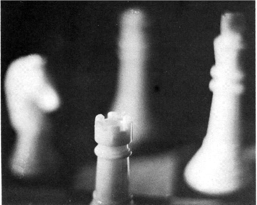
3 Holography vs. photography (from Each point in the holographic recording includes light scattered from every point in the scene, whereas each point in a photograph has light scattered only from a single point in the scene. A hologram differs from a photograph in several ways: The hologram allows the recorded scene to be viewed from a wide range of angles. The photograph gives only a single view. The reproduced range of a hologram adds many of the same depth perception cues that were present in the original scene, which are again recognized by the human brain and translated into the same perception of a three-dimensional image as when the original scene might have been viewed. The photograph is a flat two-dimensional representation. The developed hologram surface itself consists of a very fine, seemingly random pattern, which appears to bear no relationship to the scene which it has recorded. A photograph clearly maps out the light field of the original scene. When a hologram is cut in pieces, the whole scene can still be seen in each piece. When a photograph is cut in pieces, each piece shows only part of the scene. Holograms can only be viewed with very specific forms of illumination, whereas a photograph can be viewed in a wide range of lighting conditions.
4 Recording Amplitude and Phase Object Beam ( x, y) = a( x, y) exp[ jφ( x y) ] a, Reference Beam (, ) = (, ) exp ψ (, ) A xy Axy j xy Interference (, ) = (, ) + (, ) I x y A x y a x y 2 2 * * = A + a + A a+ Aa (, ) (, ) 2 (, ) (, ) cos ψ (, ) ϕ(, ) = A x y + a x y + A x y a x y x y x y
5 Reconstruction of wavefront, ( ) ( 2 2, ) ta x y = β A + a + A a+ Aa ( x y) I( x y) t A, For the reading (probe) beam of B( x, y), * (, ) (, ) B x y t x y = βaa B + βaa B + βa Ba + βaba = U + U + U + U A For B = A U3 x, y = β A a x, y ( ) ( ) 2 For B = A U4 x, y = β A a x, y ( ) ( ) 2
6 Original Referencing & Conjugate Referencing For B = A Virtual image 2 ( ) = β ( ) U3 x, y A a x, y For B = A 2 ( ) = β ( ) U4 x, y A a x, y real image U ~ a * 4 Hologram

7 Simple Hologram
8 Simple Hologram Consider Two beams cross at an angle θ Photographic plate beam 1 θ x z
9 Simple Hologram beam 1 l θ z θ x Extra path of beam 2 is l = z sin θ Displacements of two beams are E = E cos( kx ωt ) 1 o E ( ) 2 = Eo cos k x + zsinθ ωt
![Simple Hologram Thus displacement at film is: { ( ) ( [ l] )} E = E1+ E2 = Eo cos kx ω t + cos k x+ ωt Using the trig identity cos A+ cos B= 2cos A+ B cos A B ( )](/docs-images/78/78205479/images/10-0.jpg "( ) 1 1 2 2 ( ) ( 1 ) [ 1 l l] E = 2E cos k cos k x+ ωt o 2 2 Amplitude varies as Intensity varies as cos ( 1 kl) 2 2 2 2 2 2 ( 1 ) ( 1 l ) I = E cos k = cos kzsin")
10 Simple Hologram Thus displacement at film is: { ( ) ( [ l] )} E = E1+ E2 = Eo cos kx ω t + cos k x+ ωt Using the trig identity cos A+ cos B= 2cos A+ B cos A B ( ) ( ) ( ) ( 1 ) [ 1 l l] E = 2E cos k cos k x+ ωt o 2 2 Amplitude varies as Intensity varies as cos ( 1 kl) ( 1 ) ( 1 l ) I = E cos k = cos kzsin θ


11 Simple Hologram After the film is developed, lines (sinusoidal diffraction grating) appear on film. beam 1 z cos ( kz sin θ) 2 1 2
 ( ( ) ) 1 + E cos k( x zsin θ) ωt E = E cos kx ω t + E cos kz sin θ cos kx ωt 1 1 2 0 2 = E cos kx ω t + E cos k x+ zsin θ ωt 1 1 2 0 4 0 ( ) ( ) cos Acos B = cos A+ B + cos A B 1 1 2 2 4 0 ( )")
12 Simple Hologram When the beam 1 is shone on the developed film: ( 2 ) ( ) ( ) E E kz kx t 2 1 = o cos sin θ cos ω 1 2 { 1 cos sin } cos( ) = E + kz θ kx ωt o ( C) cos C = 1+ cos 2 ( ) o ( ) ( ) ( ) ( ( ) ) 1 + E cos k( x zsin θ) ωt E = E cos kx ω t + E cos kz sin θ cos kx ωt = E cos kx ω t + E cos k x+ zsin θ ωt ( ) ( ) cos Acos B = cos A+ B + cos A B ( ) beam 1?
13 Simple Hologram The three parts are: 1 E ( kx t) 2 0 cos ω Beam continuing in direction of beam 1 ( ) ( + θ ω ) E k x z t cos sin Beam in direction +θ. ( ) ( θ ω ) E k x z t cos sin Beam in direction -θ. Three beams emerge, one in direction 0, one at +θ and one at -θ.
14 You will get: Simple Hologram beam 1 Developed Photographic plate +θ θ virtual -θ θ +θ recreation of beam 2 (virtual image) -θ beam is real image real
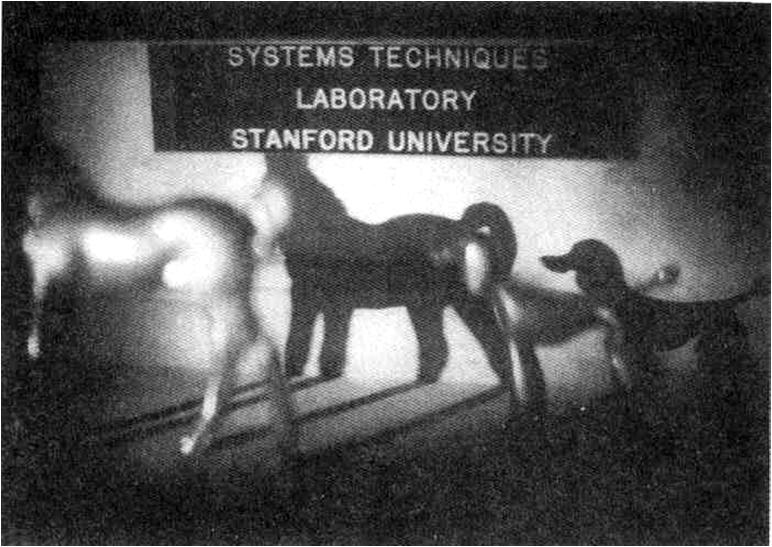
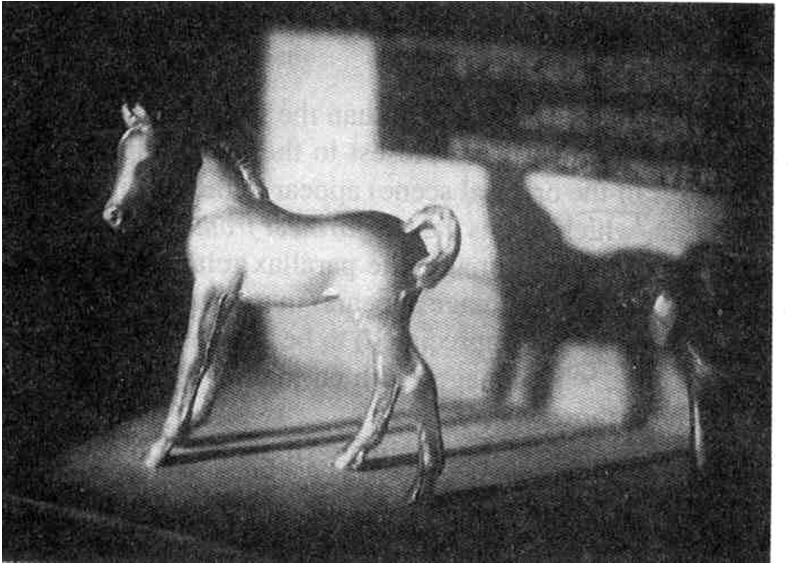
15 Holography of 3D Scenes (a) (b)

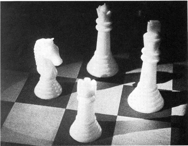
16 Parallax in Holograms
17 Holography Many different optical arrangements. Recording requirements: Laser light source(coherent light) Holographic film needs small grains. Good stability (no movements during exposure) Reconstruction requirements: Much less strict. Some do not need laser.
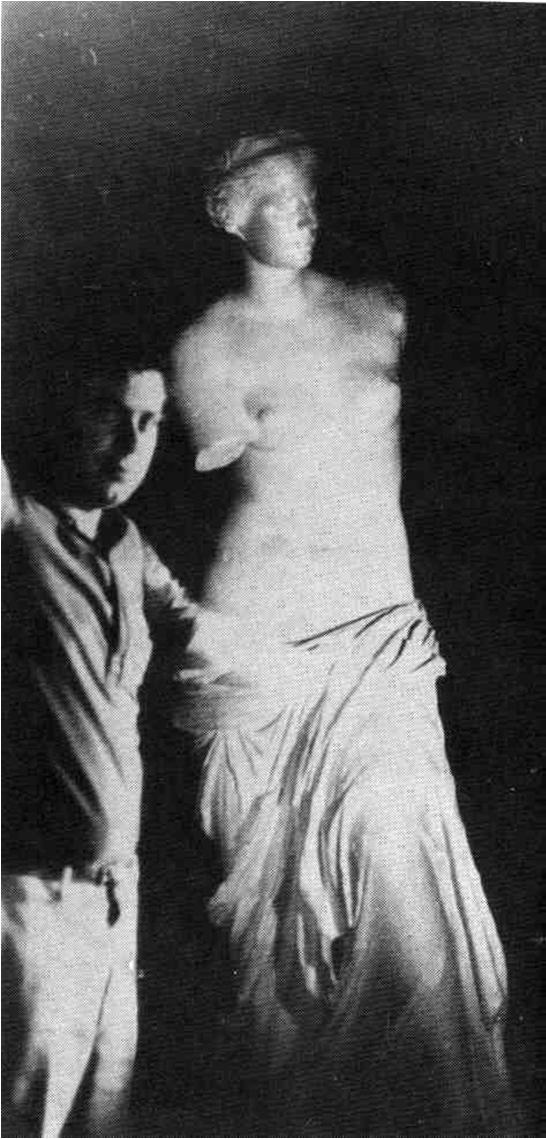
18 Applications of Holography Artistic creations. Storing & transporting delicate images Russian icons are shown as holograms. Holographic Interferometry. Strain analysis of objects under stress Used for measuring shape of objects. Data storage. Contain large amount of visual information Similar technique for storing digital data.

19 Holographic Interferometery Double exposure holographic interferometry. Two holograms on photographic plate. Object is stressed between exposures. Movement of object appears as interference fringes Real time holographic interferometry. Standard hologram of image made. Reconstruct image on top of object. Stress object & interference fringes appear.
20 Holographic Interferometery From each point on two images, light will have the displacements. ( ) ( ) E1 = Eocos kx ω t E2 = Eocos k x +Δx ωt Δx is movement of that point when object was stressed. Resultant displacement is sum of the two: 1 2 ( ) cos ( ) { cos ( )} E = E + E = E kx ω t + k x+δx ωt o x +Δx kδx = Eo cos k ω 2 t cos 2 Intensity varies as I kδx 2 2 cos Intensity shows how much (Δx) object has moved.

21 Contour Generation Double exposure hologram at the same time


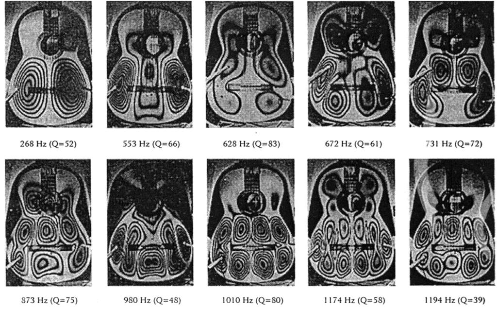
22 Vibration Analysis Double exposure hologram in sequence

23 Electronic Speckle Pattern Interferometry (ESPI)
")

24 Computer-generated hologram (CGH) 1. Detour-Phase CGH : amplitude pattern ( ) ( ) = = Δ + Δ = exp, X Y pq N p N q j pq f y q x up f j e a u U υ λ π υ φ

25 Computer-generated hologram (CGH) 2. Kinoform CGH: phase-only pattern
26 Aberration Compensation
27 Artificial Neural Networks (a) (b)
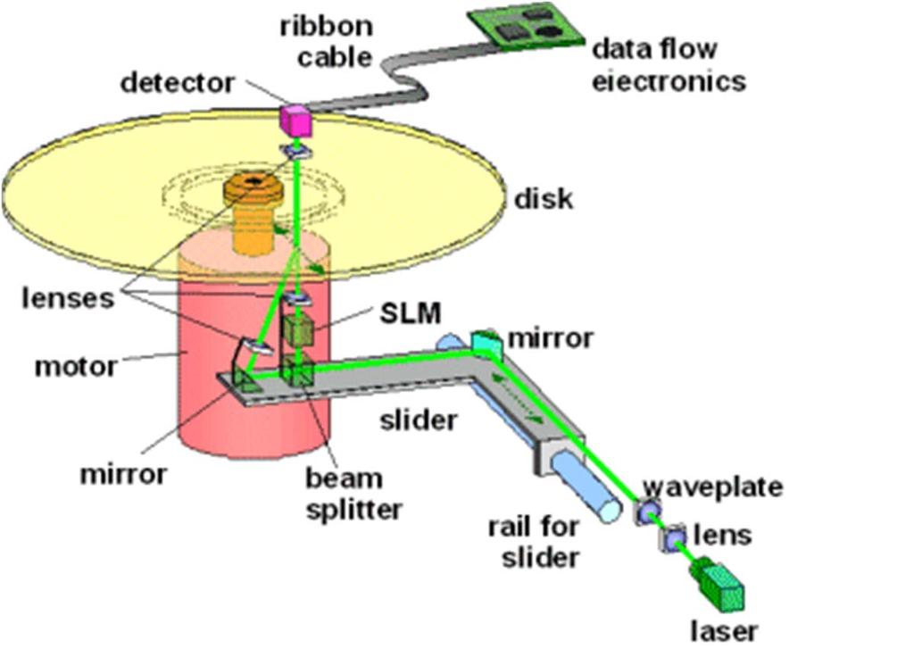
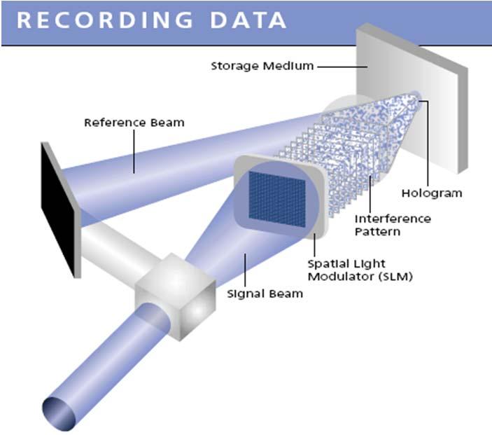
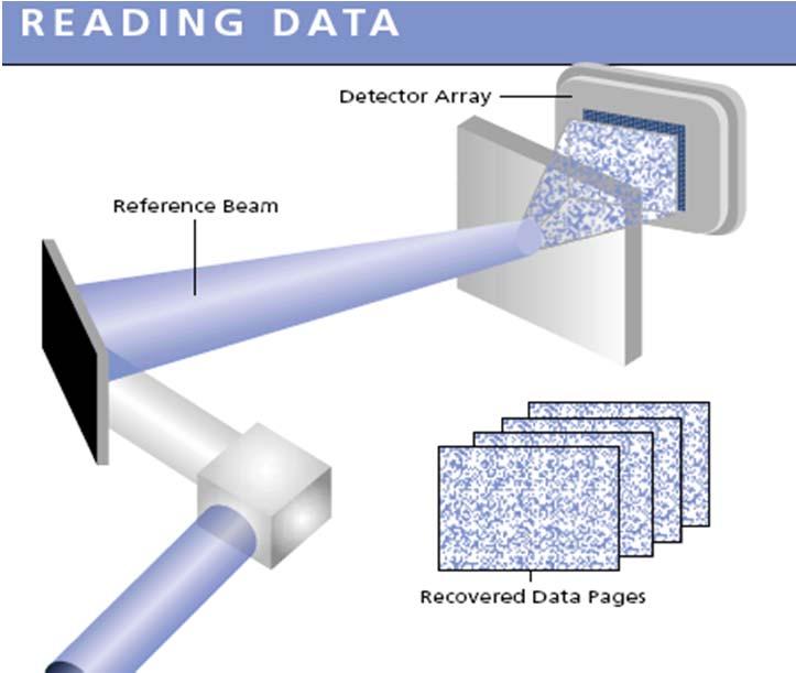
28 Holographic data storage
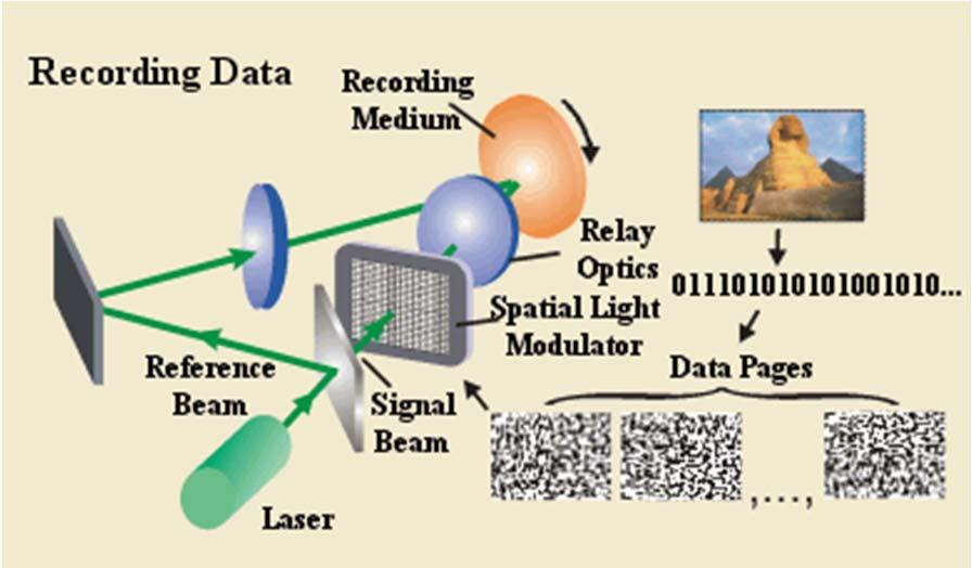
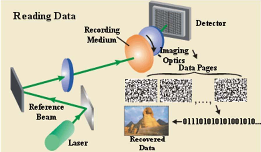
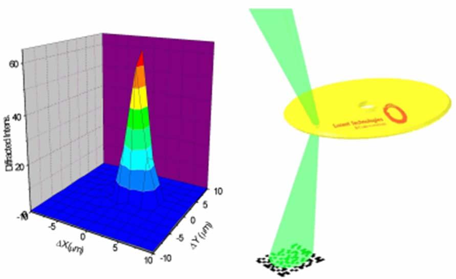
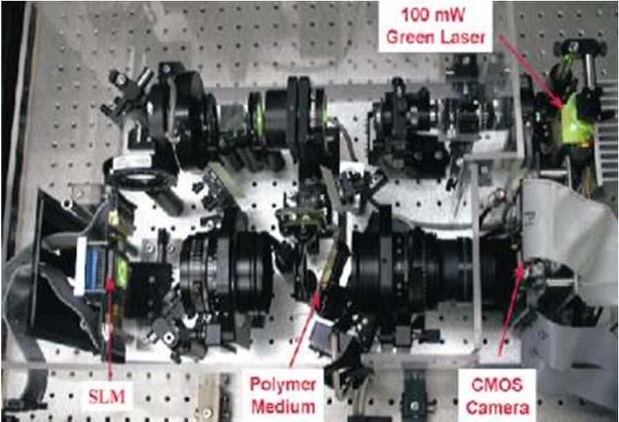
29 Holographic data storage From Lucent
Holography. How is that different than photography? How is it accomplished? Amplitude & Phase
 Holography 1948: Dennis Gabor proposes lensless imaging: wavefront reconstruction. Calls it total recording or Holo gram Concept: record and recreate wavefront incident on film. Amplitude & Phase How is
Digitalna Holografija i Primjene
 Digitalna Holografija i Primjene Hrvoje Skenderović Institut za fiziku 5. PIF Radionica, IRB, 16.12.2014. Holography Dennis Gabor invented holography in 1948 as a method for recording and reconstructing
Holography & Coherence For Holography need coherent beams Two waves coherent if fixed phase relationship between them for some period of time
 Holography & Coherence For Holography need coherent beams Two waves coherent if fixed phase relationship between them for some period of time Coherence Coherence appear in two ways Spatial Coherence Waves
Part 7 Holography. Basic Hologram Setup
 Part 7 Holography Basic Holographic Technique Light Sources Recording Materials Holographic Non-Destructive Testing Real-Time Double-Exposure Time-Average 2000 - James C. Wyant Part 7 Page 1 of 28 Basic
Tutorial Solutions. 10 Holographic Applications Holographic Zone-Plate
 10 Holographic Applications 10.1 Holographic Zone-Plate Tutorial Solutions Show that if the intensity pattern for on on-axis holographic lens is recorded in lithographic film, then a one-plate results.
d has a relationship with ψ
 Principle of X-Ray Stress Analysis Metallic materials consist of innumerable crystal grains. Each grain usually faces in a random direction. When stress is applied on such materials, the interatomic distance
Holography 24th October 2005
 24th October 2005 Contents 1 Introduction 4 2 Wavefront Reconstruction 4 2.1 Recording Amplitude and Phase................. 4 2.2 The Recording Medium...................... 6 2.2.1 Amplitude Transmittance
Shading of a computer-generated hologram by zone plate modulation
 Shading of a computer-generated hologram by zone plate modulation Takayuki Kurihara * and Yasuhiro Takaki Institute of Engineering, Tokyo University of Agriculture and Technology, 2-24-16 Naka-cho, Koganei,Tokyo
1 Laboratory #4: Division-of-Wavefront Interference
 1051-455-0073, Physical Optics 1 Laboratory #4: Division-of-Wavefront Interference 1.1 Theory Recent labs on optical imaging systems have used the concept of light as a ray in goemetrical optics to model
Draft SPOTS Standard Part III (7)
") SPOTS Good Practice Guide to Electronic Speckle Pattern Interferometry for Displacement / Strain Analysis Draft SPOTS Standard Part III (7) CALIBRATION AND ASSESSMENT OF OPTICAL STRAIN MEASUREMENTS Good
SPOTS Good Practice Guide to Electronic Speckle Pattern Interferometry for Displacement / Strain Analysis Draft SPOTS Standard Part III (7) CALIBRATION AND ASSESSMENT OF OPTICAL STRAIN MEASUREMENTS Good
Full-field optical methods for mechanical engineering: essential concepts to find one way
 Full-field optical methods for mechanical engineering: essential concepts to find one way Yves Surrel Techlab September 2004 1 Contents 1 Introduction 3 2 White light methods 4 2.1 Random encoding............................................
Fourier, Fresnel and Image CGHs of three-dimensional objects observed from many different projections
 Fourier, Fresnel and Image CGHs of three-dimensional objects observed from many different projections David Abookasis and Joseph Rosen Ben-Gurion University of the Negev Department of Electrical and Computer
Wholefield Optical Metrology: Surface Displacement Measurement
 Wholefield Optical Metrology: Surface Displacement Measurement C.R. Coggrave Phase Vision Ltd http://www.phasevision.com/ Introduction... Smooth wavefront interferometry...3 3 Holographic interferometry...5
Chapter 37. Wave Optics
 Chapter 37 Wave Optics Wave Optics Wave optics is a study concerned with phenomena that cannot be adequately explained by geometric (ray) optics. Sometimes called physical optics These phenomena include:
PHYSICS. Chapter 33 Lecture FOR SCIENTISTS AND ENGINEERS A STRATEGIC APPROACH 4/E RANDALL D. KNIGHT
 PHYSICS FOR SCIENTISTS AND ENGINEERS A STRATEGIC APPROACH 4/E Chapter 33 Lecture RANDALL D. KNIGHT Chapter 33 Wave Optics IN THIS CHAPTER, you will learn about and apply the wave model of light. Slide
HoloGraphics. Combining Holograms with Interactive Computer Graphics
 HoloGraphics Combining Holograms with Interactive Computer Graphics Gordon Wetzstein Bauhaus University Weimar [gordon.wetzstein@medien.uni-weimar.de] 1 Location Weimar Dunedin Courtesy: NASA 2 HoloGraphics
Problem Solving 10: Double-Slit Interference
 MASSACHUSETTS INSTITUTE OF TECHNOLOGY Department of hysics roblem Solving 10: Double-Slit Interference OBJECTIVES 1. To introduce the concept of interference. 2. To find the conditions for constructive
Chapter 37. Interference of Light Waves
 Chapter 37 Interference of Light Waves Wave Optics Wave optics is a study concerned with phenomena that cannot be adequately explained by geometric (ray) optics These phenomena include: Interference Diffraction
DYNAMIC ELECTRONIC SPECKLE PATTERN INTERFEROMETRY IN APPLICATION TO MEASURE OUT-OF-PLANE DISPLACEMENT
 Engineering MECHANICS, Vol. 14, 2007, No. 1/2, p. 37 44 37 DYNAMIC ELECTRONIC SPECKLE PATTERN INTERFEROMETRY IN APPLICATION TO MEASURE OUT-OF-PLANE DISPLACEMENT Pavla Dvořáková, Vlastimil Bajgar, Jan Trnka*
SIMULATION AND VISUALIZATION IN THE EDUCATION OF COHERENT OPTICS
 SIMULATION AND VISUALIZATION IN THE EDUCATION OF COHERENT OPTICS J. KORNIS, P. PACHER Department of Physics Technical University of Budapest H-1111 Budafoki út 8., Hungary e-mail: kornis@phy.bme.hu, pacher@phy.bme.hu
FRESNEL DIFFRACTION AND PARAXIAL WAVE EQUATION. A. Fresnel diffraction
 19 IV. FRESNEL DIFFRACTION AND PARAXIAL WAVE EQUATION A. Fresnel diffraction Any physical optical beam is of finite transverse cross section. Beams of finite cross section may be described in terms of
DETECTION AND QUANTIFICATION OF CRACKS IN PRESSURE VESSELS USING ESPI AND FEA MODELLS
 DETECTION AND QUANTIFICATION OF CRACKS IN PRESSURE VESSELS USING ESPI AND FEA MODELLS J GRYZAGORIDIS, DM FINDEIS, JR MYLES Department of Mechanical Engineering University of Cape Town Abstract Non destructive
MEFT / Quantum Optics and Lasers. Suggested problems from Fundamentals of Photonics Set 1 Gonçalo Figueira
 MEFT / Quantum Optics and Lasers Suggested problems from Fundamentals of Photonics Set Gonçalo Figueira. Ray Optics.-3) Aberration-Free Imaging Surface Determine the equation of a convex aspherical nonspherical)
University Physics (Prof. David Flory) Chapt_37 Monday, August 06, 2007
 Chapt_37 Monday, August 06, 2007") Name: Date: 1. If we increase the wavelength of the light used to form a double-slit diffraction pattern: A) the width of the central diffraction peak increases and the number of bright fringes within
Name: Date: 1. If we increase the wavelength of the light used to form a double-slit diffraction pattern: A) the width of the central diffraction peak increases and the number of bright fringes within
Photopolymer Diffractive Optical Elements in Electronic Speckle Pattern Shearing Interferometry
 Dublin Institute of Technology ARROW@DIT Articles Centre for Industrial and Engineering Optics 2006-01-01 Photopolymer Diffractive Optical Elements in Electronic Speckle Pattern Shearing Interferometry
INFLUENCE OF CURVATURE ILLUMINATION WAVEFRONT IN QUANTITATIVE SHEAROGRAPHY NDT MEASUREMENT
 1 th A-PCNDT 6 Asia-Pacific Conference on NDT, 5 th 1 th Nov 6, Auckland, New Zealand INFLUENCE OF CURVATURE ILLUMINATION WAVEFRONT IN QUANTITATIVE SHEAROGRAPHY NDT MEASUREMENT Wan Saffiey Wan Abdullah
MEASUREMENT OF THE WAVELENGTH WITH APPLICATION OF A DIFFRACTION GRATING AND A SPECTROMETER
 Warsaw University of Technology Faculty of Physics Physics Laboratory I P Irma Śledzińska 4 MEASUREMENT OF THE WAVELENGTH WITH APPLICATION OF A DIFFRACTION GRATING AND A SPECTROMETER 1. Fundamentals Electromagnetic
Interference. Electric fields from two different sources at a single location add together. The same is true for magnetic fields at a single location.
 Interference Electric fields from two different sources at a single location add together. The same is true for magnetic fields at a single location. Thus, interacting electromagnetic waves also add together.
ECE 4606 Undergraduate Optics Lab Holography. Holography. Outline. Subject of the Nobel prize in Physics to Gabor in 1971
 Holography C 4606 Undergraduate ptics Lab Holography utline Subject of the Nobel prize in Physics to Gabor in 1971 Basics Thin absorption holograms More considerations for thin holograms obert. McLeod,
High spatial resolution measurement of volume holographic gratings
 High spatial resolution measurement of volume holographic gratings Gregory J. Steckman, Frank Havermeyer Ondax, Inc., 8 E. Duarte Rd., Monrovia, CA, USA 9116 ABSTRACT The conventional approach for measuring
Control of Light. Emmett Ientilucci Digital Imaging and Remote Sensing Laboratory Chester F. Carlson Center for Imaging Science 8 May 2007
 Control of Light Emmett Ientilucci Digital Imaging and Remote Sensing Laboratory Chester F. Carlson Center for Imaging Science 8 May 007 Spectro-radiometry Spectral Considerations Chromatic dispersion
Optics Vac Work MT 2008
 Optics Vac Work MT 2008 1. Explain what is meant by the Fraunhofer condition for diffraction. [4] An aperture lies in the plane z = 0 and has amplitude transmission function T(y) independent of x. It is
We are IntechOpen, the world s leading publisher of Open Access books Built by scientists, for scientists. International authors and editors
 We are IntechOpen, the world s leading publisher of Open Access books Built by scientists, for scientists 3,800 116,000 120M Open access books available International authors and editors Downloads Our
9.0 Special Interferometric Tests for Aspherical Surfaces
 9.0 Special Interferometric Tests for Aspherical Surfaces 9.0 Special Interferometric Tests for Aspherical Surfaces - I n 9.1 Aspheric Surfaces 9.1.1 Conic 9.1.2 Sag for Aspheres n 9.2 Null Test 9.2.1
Wave Front Reconstruction from Off-Axis Holograms Using Four-Quarter Phase Shifting Method
 Journal of Sciences, Islamic Republic of Iran 18(1): 67-74 (007) University of Tehran, ISSN 1016-1104 http://jsciences.ut.ac.ir Wave Front Reconstruction from Off-Axis Holograms Using Four-Quarter Phase
Invited Paper. Nukui-Kitamachi, Koganei, Tokyo, , Japan ABSTRACT 1. INTRODUCTION
 Invited Paper Wavefront printing technique with overlapping approach toward high definition holographic image reconstruction K. Wakunami* a, R. Oi a, T. Senoh a, H. Sasaki a, Y. Ichihashi a, K. Yamamoto
Introduction to Computer-Based Holography
 Mitglied der Helmholtz-Gemeinschaft Introduction to Computer-Based Holography October 29, 2013 Carsten Karbach, Jülich Supercomputing Centre (JSC) Why computergenerated holography? Applications Source:
Chapter 8: Physical Optics
 Chapter 8: Physical Optics Whether light is a particle or a wave had puzzled physicists for centuries. In this chapter, we only analyze light as a wave using basic optical concepts such as interference
14 Chapter. Interference and Diffraction
 14 Chapter Interference and Diffraction 14.1 Superposition of Waves... 14-14.1.1 Interference Conditions for Light Sources... 14-4 14. Young s Double-Slit Experiment... 14-4 Example 14.1: Double-Slit Experiment...
Chapter 37 HW Q: 2, 4, 7, 10, P: 4, 8, 13, 19, 21, 28, 31, 36, 42, 59, 62
 Chapter 37 HW Q: 2, 4, 7, 10, P: 4, 8, 13, 19, 21, 28, 31, 36, 42, 59, 62 Wave Interference y = y 1 +y 2 = 2A cos (φ/2) sin (kx - ωt + φ/2) Δφ Resultant Amplitude: 2Acos 2 Constructive Interference: Δ
INTERFERENCE. where, m = 0, 1, 2,... (1.2) otherwise, if it is half integral multiple of wavelength, the interference would be destructive.
 otherwise, if it is half integral multiple of wavelength, the interference would be destructive.") 1.1 INTERFERENCE When two (or more than two) waves of the same frequency travel almost in the same direction and have a phase difference that remains constant with time, the resultant intensity of light
1.1 INTERFERENCE When two (or more than two) waves of the same frequency travel almost in the same direction and have a phase difference that remains constant with time, the resultant intensity of light
Experiment 8 Wave Optics
 Physics 263 Experiment 8 Wave Optics In this laboratory, we will perform two experiments on wave optics. 1 Double Slit Interference In two-slit interference, light falls on an opaque screen with two closely
Past Paper Questions Waves
 Past Paper Questions Waves Name 1. Explain the differences between an undamped progressive transverse wave and a stationary transverse wave, in terms of amplitude, (ii) phase and (iii) energy transfer.
Reflections from a thin film
 Reflections from a thin film l Part of the wave reflects from the top surface and part from the bottom surface l The part that reflects from the top surface has a 180 o phase change while the part that
Formulas of possible interest
 Name: PHYS 3410/6750: Modern Optics Final Exam Thursday 15 December 2011 Prof. Bolton No books, calculators, notes, etc. Formulas of possible interest I = ɛ 0 c E 2 T = 1 2 ɛ 0cE 2 0 E γ = hν γ n = c/v
Diffraction-based approaches to the in-situ measurement of dimensional variations in components produced by thermoplastic micro- and nano-embossing
 Diffraction-based approaches to the in-situ measurement of dimensional variations in components produced by thermoplastic micro- and nano-embossing Hayden Taylor and Duane Boning 23 January 2008 Microsystems
To see how a sharp edge or an aperture affect light. To analyze single-slit diffraction and calculate the intensity of the light
 Diffraction Goals for lecture To see how a sharp edge or an aperture affect light To analyze single-slit diffraction and calculate the intensity of the light To investigate the effect on light of many
E x Direction of Propagation. y B y
 x E x Direction of Propagation k z z y B y An electromagnetic wave is a travelling wave which has time varying electric and magnetic fields which are perpendicular to each other and the direction of propagation,
Lecture 39. Chapter 37 Diffraction
 Lecture 39 Chapter 37 Diffraction Interference Review Combining waves from small number of coherent sources double-slit experiment with slit width much smaller than wavelength of the light Diffraction
Aberrations in Holography
 Aberrations in Holography D Padiyar, J Padiyar 1070 Commerce St suite A, San Marcos, CA 92078 dinesh@triple-take.com joy@triple-take.com Abstract. The Seidel aberrations are described as they apply to
Simple, complete, and novel quantitative model of holography for students of science and science education
 Journal of Physics: Conference Series Simple, complete, and novel quantitative model of holography for students of science and science education To cite this article: Dale W Olson 2013 J. Phys.: Conf.
Chapter 38 Wave Optics (II)
") Chapter 38 Wave Optics (II) Initiation: Young s ideas on light were daring and imaginative, but he did not provide rigorous mathematical theory and, more importantly, he is arrogant. Progress: Fresnel,
Chapter 38 Wave Optics (II) Initiation: Young s ideas on light were daring and imaginative, but he did not provide rigorous mathematical theory and, more importantly, he is arrogant. Progress: Fresnel,
REMOTE SENSING OF SURFACE STRUCTURES
 REMOTE SENSING OF SURFACE STRUCTURES A.W. Koch, P. Evanschitzky and M. Jakobi Technische Universität München Institute for Measurement Systems and Sensor Technology D-8090 München, Germany Abstract: The
Auburn Hills, MI, USA, 2 Dept. of Mechanical Engineering, Oakland University, Rochester, MI, USA
 APPLICATIONS OF FULL FIELD OPTICAL METHOD FOR MEASURING STRAIN CONCENTRATION L. Zhang 1,, C. Du 1, Y.J. Zhou 1 and L.X. Yang 1 DaimlerChrysler Corporation, Advanced Stamping Manufacturing Engineering,
Metrology and Sensing
 Metrology and Sensing Lecture 4: Fringe projection 2016-11-08 Herbert Gross Winter term 2016 www.iap.uni-jena.de 2 Preliminary Schedule No Date Subject Detailed Content 1 18.10. Introduction Introduction,
Lecture Notes on Wave Optics (04/23/14) 2.71/2.710 Introduction to Optics Nick Fang
 2.71/2.710 Introduction to Optics Nick Fang") .7/.70 Introduction to Optics Nic Fang Outline: Fresnel Diffraction The Depth of Focus and Depth of Field(DOF) Fresnel Zones and Zone Plates Holography A. Fresnel Diffraction For the general diffraction
.7/.70 Introduction to Optics Nic Fang Outline: Fresnel Diffraction The Depth of Focus and Depth of Field(DOF) Fresnel Zones and Zone Plates Holography A. Fresnel Diffraction For the general diffraction
LED holographic imaging by spatial-domain diffraction computation of. textured models
 LED holographic imaging by spatial-domain diffraction computation of textured models Ding-Chen Chen, Xiao-Ning Pang, Yi-Cong Ding, Yi-Gui Chen, and Jian-Wen Dong* School of Physics and Engineering, and
MICHELSON S INTERFEROMETER
 MICHELSON S INTERFEROMETER Objectives: 1. Alignment of Michelson s Interferometer using He-Ne laser to observe concentric circular fringes 2. Measurement of the wavelength of He-Ne Laser and Na lamp using
Second International Conference on Photomechanics and Speckle Metrology
 PROCEEDINGS REPRINT ~ SPIE-The International Society for Optical Engineering Reprinted from Second International Conference on Photomechanics and Speckle Metrology, Speckle Techniques, Birefringence Methods,
Center for Nondestructive Evaluation The Johns Hopkins University Baltimore, Maryland 21218
 HIGH RESOLUTION HOLOGRAPHIC CONTOURING James W. Wagner Center for Nondestructive Evaluation The Johns Hopkins University Baltimore, Maryland 21218 INTRODUCTION Optical contouring techniques which incorporate
Analysis of an Effect of Perturbations in SWHM and Illuminating Optical Scheme Parameters on an Aerial Image
 Analysis of an Effect of Perturbations in SWHM and Illuminating Optical Scheme Parameters on an Aerial Image Borisov M.V., Chelyubeev D.A., Chernik V.V., Gavrikov A.A., Knyazkov D.Yu., Mikheev P.A., Rakhovskіy
Development of shape measuring system using a line sensor in a lateral shearing interferometer
 Development of shape measuring system using a line sensor in a lateral shearing interferometer Takashi NOMURA*a, Kazuhide KAMIYA*a, Akiko NAGATA*a, Hatsuzo TASHIRO **b, Seiichi OKUDA ***c a Toyama Prefectural
Securing of Two and Three Dimensional Information Based on In-line Digital Holography
 Securing of Two and Three Dimensional Information Based on In-line Digital Holography Hesham Eldeeb Computer & System Department Electronic Research Institute National Research Center, Dokki, Giza Cairo,
Mahdi Amiri. May Sharif University of Technology
 Course Presentation Multimedia Systems 3D Technologies Mahdi Amiri May 2014 Sharif University of Technology Binocular Vision (Two Eyes) Advantages A spare eye in case one is damaged. A wider field of view
Laser sensors. Transmitter. Receiver. Basilio Bona ROBOTICA 03CFIOR
 Mobile & Service Robotics Sensors for Robotics 3 Laser sensors Rays are transmitted and received coaxially The target is illuminated by collimated rays The receiver measures the time of flight (back and
Using a multipoint interferometer to measure the orbital angular momentum of light
 CHAPTER 3 Using a multipoint interferometer to measure the orbital angular momentum of light Recently it was shown that the orbital angular momentum of light can be measured using a multipoint interferometer,
Physics Midterm I
 Phys121 - February 6, 2009 1 Physics 121 - Midterm I Last Name First Name Student Number Signature Tutorial T.A. (circle one): Ricky Chu Firuz Demir Maysam Emadi Alireza Jojjati Answer ALL 10 questions.
Chapter 38. Diffraction Patterns and Polarization
 Chapter 38 Diffraction Patterns and Polarization Diffraction Light of wavelength comparable to or larger than the width of a slit spreads out in all forward directions upon passing through the slit This
NOVEL TEMPORAL FOURIER-TRANSFORM SPECKLE PATTERN SHEARING INTERFEROMETER
 NOVEL TEMPORAL FOURIER-TRANSFORM SPECKLE PATTERN SHEARING INTERFEROMETER C. Joenathan*, B. Franze, P. Haible, and H. J. Tiziani Universitaet Stuttgart, Institut fuer Technische Optik, Pfaffenwaldring 9,
Flatness Measurement of a Moving Object Using Shadow Moiré Technique with Phase Shifting
 Flatness Measurement of a Moving Object Using Shadow Moiré Technique with Phase Shifting Jiahui Pan, Dirk Zwemer, Gregory Petriccione, and Sean McCarron AkroMetrix, LLC, 700 NE Expy., C-100, Atlanta, GA,
Holographic Method for Extracting Three-Dimensional Information with a CCD Camera. Synopsis
 Mem. Fac. Eng., Osaka City Univ., Vol. 36,pp. 1-11.(1995) Holographic Method for Extracting Three-Dimensional Information with a CCD Camera by Hideki OKAMOTO*, Hiroaki DEDA*, Hideya TAKAHASHI**, and Eiji
Chapter 2: Wave Optics
 Chapter : Wave Optics P-1. We can write a plane wave with the z axis taken in the direction of the wave vector k as u(,) r t Acos tkzarg( A) As c /, T 1/ and k / we can rewrite the plane wave as t z u(,)
Physical & Electromagnetic Optics: Diffraction Gratings
 31/05/2018 Physical & Electromagnetic Optics: Diffraction Gratings Optical Engineering Prof. Elias N. Glytsis School of Electrical & Computer Engineering National Technical University of Athens Multiple
13. Brewster angle measurement
 13. Brewster angle measurement Brewster angle measurement Objective: 1. Verification of Malus law 2. Measurement of reflection coefficient of a glass plate for p- and s- polarizations 3. Determination
Module 18: Diffraction-I Lecture 18: Diffraction-I
 Module 18: iffraction-i Lecture 18: iffraction-i Our discussion of interference in the previous chapter considered the superposition of two waves. The discussion can be generalized to a situation where
Digital Pulse Acoustic Lensless Fourier Method for Ultrasonic Imaging
 Bulg. J. Phys. 34 (2007) 59 70 Digital Pulse Acoustic Lensless Fourier Method for Ultrasonic Imaging A. Andreeva, M. Burova, J. Burov Faculty of Physics, University of Sofia, 5 James Bourchier Blvd., Sofia
Applications of Piezo Actuators for Space Instrument Optical Alignment
 Year 4 University of Birmingham Presentation Applications of Piezo Actuators for Space Instrument Optical Alignment Michelle Louise Antonik 520689 Supervisor: Prof. B. Swinyard Outline of Presentation
STUDY ON LASER SPECKLE CORRELATION METHOD APPLIED IN TRIANGULATION DISPLACEMENT MEASUREMENT
 STUDY ON LASER SPECKLE CORRELATION METHOD APPLIED IN TRIANGULATION DISPLACEMENT MEASUREMENT 2013 г. L. Shen*, D. G. Li*, F. Luo** * Huazhong University of Science and Technology, Wuhan, PR China ** China
Measurement of Highly Parabolic Mirror using Computer Generated Hologram
 Measurement of Highly Parabolic Mirror using Computer Generated Hologram Taehee Kim a, James H. Burge b, Yunwoo Lee c a Digital Media R&D Center, SAMSUNG Electronics Co., Ltd., Suwon city, Kyungki-do,
Holographic measurement and synthesis of optical field using a spatial light modulator
 Holographic measurement and synthesis of optical field using a spatial light modulator Joonku Hahn NCRCAPAS School of Electrical Engineering Seoul National University Introduction Overview of digital holography
Experiment 1: Diffraction from a Single Slit
 012-05880D Slit Accessory Experiment 1: Diffraction from a Single Slit Purpose Theory EQUIPMENT REQUIRED track and from the Basic Optics System (OS-8515) Diode Laser (OS-8525) Single Slit Disk (OS-8523)
Winter College on Optics in Environmental Science February Adaptive Optics: Introduction, and Wavefront Correction
 2018-23 Winter College on Optics in Environmental Science 2-18 February 2009 Adaptive Optics: Introduction, and Wavefront Correction Love G. University of Durham U.K. Adaptive Optics: Gordon D. Love Durham
G3 TWO-SOURCE INTERFERENCE OF WAVES
 G3 TWO-SOURCE INTERFERENCE OF WAVES G4 DIFFRACTION GRATINGS HW/Study Packet Required: READ Tsokos, pp 624-631 SL/HL Supplemental: Hamper, pp 424-428 DO Questions pp 631-632 #1,3,8,9,10 REMEMBER TO. Work
Interference of Light
 Lecture 22 Chapter 22 Physics II Wave Optics: Interference of Light Course website: http://faculty.uml.edu/andriy_danylov/teaching/physicsii Wave Motion Interference Models of Light (Water waves are Easy
PHYS 1402 DIFFRACTION AND INTERFERENCE OF LIGHT: MEASURE THE WAVELENGTH OF LIGHT
 PHYS 1402 DIFFRACTION AND INTERFERENCE OF LIGHT: MEASURE THE WAVELENGTH OF LIGHT I. OBJECTIVE The objective of this experiment is to observe the interference pattern from a double slit and a diffraction
Coupling of surface roughness to the performance of computer-generated holograms
 Coupling of surface roughness to the performance of computer-generated holograms Ping Zhou* and Jim Burge College of Optical Sciences, University of Arizona, Tucson, Arizona 85721, USA *Corresponding author:
Vibration parameter measurement using the temporal digital hologram sequence and windowed Fourier transform
 THEORETICAL & APPLIED MECHANICS LETTERS 1, 051008 (2011) Vibration parameter measurement using the temporal digital hologram sequence and windowed Fourier transform Chong Yang, 1, 2 1, a) and Hong Miao
Today s Outline - April 17, C. Segre (IIT) PHYS Spring 2018 April 17, / 22
 PHYS Spring 2018 April 17, / 22") Today s Outline - April 17, 2018 C. Segre (IIT) PHYS 570 - Spring 2018 April 17, 2018 1 / 22 Today s Outline - April 17, 2018 Diffraction enhanced imaging C. Segre (IIT) PHYS 570 - Spring 2018 April 17,
Today s Outline - April 17, 2018 C. Segre (IIT) PHYS 570 - Spring 2018 April 17, 2018 1 / 22 Today s Outline - April 17, 2018 Diffraction enhanced imaging C. Segre (IIT) PHYS 570 - Spring 2018 April 17,
Projection of speckle patterns for 3D sensing
 Journal of Physics: Conference Series Projection of speckle patterns for 3D sensing To cite this article: J García et al 008 J. Phys.: Conf. Ser. 139 0106 View the article online for updates and enhancements.
Secondary grating formation by readout at Bragg-null incidence
 Secondary grating formation by readout at Bragg-null incidence Ali Adibi, Jose Mumbru, Kelvin Wagner, and Demetri Psaltis We show that when a dynamic hologram is read out by illumination at the Bragg nulls
Ray Optics. Lecture 23. Chapter 23. Physics II. Course website:
 Lecture 23 Chapter 23 Physics II Ray Optics Course website: http://faculty.uml.edu/andriy_danylov/teaching/physicsii Let s finish talking about a diffraction grating Diffraction Grating Let s improve (more
Waves & Oscillations
 Physics 42200 Waves & Oscillations Lecture 42 Review Spring 2013 Semester Matthew Jones Final Exam Date:Tuesday, April 30 th Time:1:00 to 3:00 pm Room: Phys 112 You can bring two double-sided pages of
Downloaded from UNIT 06 Optics
 1 Mark UNIT 06 Optics Q1: A partially plane polarised beam of light is passed through a polaroid. Show graphically the variation of the transmitted light intensity with angle of rotation of the Polaroid.
3. Image formation, Fourier analysis and CTF theory. Paula da Fonseca
 3. Image formation, Fourier analysis and CTF theory Paula da Fonseca EM course 2017 - Agenda - Overview of: Introduction to Fourier analysis o o o o Sine waves Fourier transform (simple examples of 1D
Overview of techniques applicable to self-interference incoherent digital holography
 J. Europ. Opt. Soc. Rap. Public. 8, 13077 (2013) www.jeos.org Overview of techniques applicable to self-interference incoherent digital holography J. Hong jisoohong@mail.usf.edu Department of Physics,
Wave Phenomena Physics 15c
 Wave Phenomena Physics 15c Lecture 23 Coherence Laser, Holography CUE Evaluation! This course is being evaluated because the course head has requested that the course be included in the CUE Guide. As you
Consideration of time to create real-time video of a kinoform using a web camera
 Consideration of time to create real-time video of a kinoform using a web camera Masataka Tozuka Kunihiko Takano Makoto Ohki Koki Sato Optical Engineering 50(9), 091306 (September 2011) Consideration of
Optics Wave Behavior in Optics Diffraction
 Optics Wave Behavior in Optics Diffraction Lana Sheridan De Anza College June 15, 2018 Last time Interference of light: the Double-Slit experiment multiple slit interference diffraction gratings Overview
s70 Prototype of a Handheld Displacement Measurement System Using Multiple Imaging Sensors
 Journal of JSEM, Vol.15, Special Issue (2015) s70-s74 Copyright C 2015 JSEM Prototype of a Handheld Displacement Measurement System Using Multiple Imaging Sensors Motoharu FUJIGAKI 1, Hiroki MIAMIO 2,
EVALUATION OF DIGITAL HOLOGRAPHIC RECONSTRUCTION TECHNIQUES FOR USE IN ONE-SHOT MULTI-ANGLE HOLOGRAPHIC TOMOGRAPHY
 EVALUATION OF DIGITAL HOLOGRAPHIC RECONSTRUCTION TECHNIQUES FOR USE IN ONE-SHOT MULTI-ANGLE HOLOGRAPHIC TOMOGRAPHY Thesis Submitted to The School of Engineering of the UNIVERSITY OF DAYTON In Partial Fulfillment