Chapters 1 4: Overview
|
|
|
- Earl Holland
- 6 years ago
- Views:
Transcription
1 Chapters 1 4: Overview Photogrammetry: introduction, applications, and tools GNSS/INS-assisted photogrammetric and LiDAR mapping LiDAR mapping: principles, applications, mathematical model, and error sources and their impact. QA/QC of LiDAR mapping Quaternions & rotation in space This chapter will be focusing on the different alternatives for the registration of laser scans. Point-based registration, Feature-based registration, and Image-based registration 1
2 Chapter 6 REGISTRATION OF LASER SCANNING POINT CLOUDS 2
3 Outline Introduction: Terrestrial Laser Scanners (TLS) and applications Prior work: Registration paradigm, point-based registration, feature-based registration Methodology: Linear features extraction, parameter estimation alternatives, matching process, and parameter refinement Experimental results: Segmentation and registration results Conclusions and future work 3


4 Terrestrial Laser Scanners FARO Focus3D X ,000 points/second 330 m range ±2 mm range error * Leica Scanner P20 1 million points/second 120 m range ±6mm at100 M position error * Terrestrial Laser Scanner (TLS) refers to LiDAR equipment that is mounted on a tripod. 4
5 Terrestrial Laser Scanners Laser ranging A Object Terrestrial Laser Scanner* * 5


6 Terrestrial Laser Scanners Laser ranging Laser unit coordinate system β A Laser beam coordinate system Object Terrestrial Laser Scanner* * The delivered point cloud will be relative to the laser unit coordinate system. 6


7 Introduction: TLS Applications Digital Building Model generation, Cultural heritage documentation, Industrial site modeling, Landslide hazard analysis, and Many other civilian and military applications

8 Introduction: TLS Applications 3D modeling of electrical substations 8
 require")


9 Introduction: TLS Registration Complex surfaces (or objects) require multiple scans with overlap for a full 3D model: The separate point clouds must be registered to a common reference frame. Original Scans Registered Scans 9
10 Introduction: TLS Registration Complex surfaces (or objects) require multiple scans with overlap for a full 3D model: The separate point clouds must be registered to a common reference frame. X n =? Y n =? Z n =? ω n =? φ n =? κ n =? ST2 ST1 ST3 ST4 ST5 ST8 ST7 ST6 10
11 Introduction: TLS Registration 11
12 Introduction: Coarse Vs. Fine Registration Transformation Parameters using linear features Coarse Registration Fine Registration 12


13 Introduction: Coarse Vs. Fine Registration After Coarse Registration After Fine Registration 13
14 Registration and Mobile LiDAR Data For LiDAR data, which has been captured by a mobile system whether terrestrial or airborne, the point cloud will be given relative to a unified coordinate system. Defined by the onboard GNSS/INS unit Registration is not necessary for this type of data. However, in some situations, systematic errors in the data acquisition system will lead to discrepancies among overlapping point clouds. Therefore, we might need to register overlapping mobile LiDAR data. The impact of the systematic errors will lead to coarsely To ensure the alignment of the different datasets, and registered datasets. Thus we need to only worry about the To evaluate the fine quality registration of the system of such performance data. (QC). 14
15 Introduction: TLS & ALS Registration 15
16 Registration Paradigm Elements Registration Primitives Transformation Parameters Similarity Measure Matching Strategy Features that will be identified in the individual scans, e.g. Points, Lines, and Planar features Transformation parameters that describe the relationship between the reference frames of the different scans Describes the coincidence of conjugate primitives after registering different scans to a common reference frame Controlling framework which is used for manipulating primitives, transformation parameters, and similarity measure (Habib A. & Al-Ruzouq R., 2004) 16
17 Registration using Exact Point Correspondence Fine Registration 17
.")

18 Registration: Prior Work Registration is performed using corresponding points, which could be signalized targets). ~10 cm Example of targets used in the registration of terrestrial laser scans (photos courtesy of leica-geosystems) 18

19 Registration: Prior Work Targets for ALS registration ~1 m Example of targets used in the registration of airborne laser scans under special circumstance (photo courtesy of Csanyi & Toth, 2007) 19
20 Registration: Point-Based Mathematical Model and are corresponding points in scans and, respectively; is the coordinate of relative to the reference frame of scan ; is the coordinate of relative to the reference frame of scan ; is the shift between the reference frames of the two scans (relative to the reference frame of scan ); is the rotation matrix between the reference frames of the two scans; and S is For the scale LiDAR factor. data, the scale might not be necessary. 20
21 Registration: Horn s Approach Closed form solution, which is based on least-squares adjustment, for estimating the transformation parameters relating two 3D coordinate systems using corresponding points (Horn, 1987) Procedure: Estimate the rotation matrix, Estimate the scale factor, and Estimate the shifts. 21
22 Registration: Horn s Approach Rotation Estimation: / & / 22
23 Registration: Horn s Approach Rotation Estimation: The first step is evaluating the centroid of the points in each dataset: & Subtract the centroid from each of the coordinates of the different points in both datasets & derive the corresponding unit vector: Then, we can write the following constraint: 23
24 Registration: Horn s Approach Rotation Estimation: Using quaternions, we can derive the rotation matrix through the following procedure. We need to derive Errors. min that minimizes the Sum of Squared min min 2 24
25 Quaternion-Based Derivation of Rotation Estimation: min Note: min 2 & are always +ve. Thus: is minimized when maximized is 25
26 Quaternion-Based Derivation of Rotation Estimation: max max max max max. max max.. max. 26
27 Quaternion-Based Derivation of Rotation Estimation: 27
28 Quaternion-Based Derivation of Rotation Estimation:,,,, Remember that & are pure quaternions. Trace ( ) = 0 Trace = 0 28
29 Quaternion-Based Derivation of Rotation Estimation: max, 1 max This is the case only when is the eigenvector of. will be maximum when is the eigenvector of that corresponds to the largest eigenvalue. 29
30 Quaternion-Based Derivation of Rotation Estimation:
31 Estimation of the Scale Factor & Translation Scale and Shift Estimation: The scale factor can be derived according to the following formula: / The translation component can be estimated as follows: 31
32 Point-Based Registration without Exact Point-to-Point Correspondence Fine Registration 32
33 Registration: Prior Work Commonly Adopted Point-Based Registration Methodologies without Exact Point-to-Point Correspondence: The Iterative Closest Point ICP (Besl and Mckay, 1992) The Iterative Closest Patch ICPatch (Habib et al., 2010) The Iterative Closest Projected Point ICPP (Al-Durgham et al., 2011) Point-based registration methodologies require good initial approximations of the transformation parameters, which could be established through manual interaction. 33
34 Registration: Prior Work Iterative Closest Point (ICP): Note: ICP assumes point-to-point correspondence which is invalid among LiDAR points due to the irregular sampling nature of the points. 34
35 Registration: Prior Work Iterative Closest Point (ICP): Besl and McKay (1992) Points as primitives 3D rigid body transformation Minimizes Euclidian distances Performed iteratively Problem: Exact point correspondences cannot be guaranteed when dealing with irregular point clouds. Surface 1 Surface 2 Iteration 1 Iteration 2 35
36 Registration: Prior Work Iterative Closest Point (ICP): Chen and Medioni (1992) Points and planes as primitives Minimizes normal distances Prerequisite: The algorithm requires local plane fitting. Surface 1 Surface 2 Iteration 1 Iteration 2 36
37 Registration: Prior Work Iterative Closest Point (ICP): Variants Points and triangular irregular network (TIN) patches 3D similarity transformation Coplanarity constraint and modified weight matrix Performed iteratively Surface 1 Surface 2 Iteration 1 Iteration 2 ICPatch 37
38 Registration: Prior Work Iterative Closest Patch (ICPatch): 38
39 Registration: Prior Work Iterative Closest Patch (ICPatch): Conditions for valid conjugate point-patch pairs: Triangular patch Δp 1 p 2 p 3 must be the closest to the transformed point p t, i.e. n=min. The normal distance, n, must be within a threshold. The projection of p t, p, must fall within Δp 1 p 2 p 3. p 3D Similarity Transformation S 1 S 2 p t p p 3 p t n p 1 p 2 39
40 Registration: Prior Work Iterative Closest Patch (ICPatch): Similarity Measure: p 1, p 2, p 3 and p t are assumed to be coplanar, i.e. the volume of the pyramid formed by vertices p 1, p 2, p 3 and p t should be zero. p 3 p t p 1 p 2 X Y Z X Y Z X Y Z X Y Z p p p t t t p p p det 0 p p p p p p
41 Registration: Prior Work Iterative Closest Patch (ICPatch): Similarity measure: p 3 = p t + random & systematic errors Correspondence assumption is not true. Point-based procedure, while using non-conjugate points from a valid point-patch pair Z Modify weights so the misclosure vector is minimized in the direction normal to the TIN patch. U p Y X V 1 W V V 3 p t U 41 V 2 X V M Y W Z Q M Q M 1 1 T UVW XYZ Weight restriction Q ' UVW qw 1 T 1 XYZ ' UVW Q' M Q M
42 Registration: Prior Work Iterative Closest Projected Point (ICPP): For a point in S 1, find the closest three points in S 2. A match is established between a point in S 1 and a triangle,, in S 2. The pair (, ) is used for matching through the conventional ICP techniques, thus named the ICPP. 0 Conditions:,,, Compatible surface normals 42
43 Feature-Based Registration Coarse Registration 43
44 Registration: Prior Work Registration Methodologies Based on Linear and Planar Features: Linear and planar features provide strong link between laser scans, and a good initial approximation of the transformation parameters is not required. Linear and planar features can be utilized to register TLS data using different features individually and also by combining some of them (Jaw and Chuang,2008). Photogrammetric data can be incorporated to take advantage of additional information (Canaz and Habib, 2013). Manual identification of conjugate features is usually required. 44
45 Registration: Prior Work Registration Methodologies Based on Linear and Planar Features: An automatic registration method of laser scans using extracted linear and planar features is proposed by Yao et al., Measures that describe the shape and distribution of groups of linear features in 3D space are proposed. The line-based approach usually failed in outdoor environments. Sensitive to existing symmetries present in the extracted features 45
46 Registration: Prior Work Registration Based on Linear Features: Z Line Y Line b Coordinate System 1 2 shifts across the line direction 2 rotation angles defined by the line direction X 1 shift 1 rotation 1 scale Z Y Line Line X Coordinate System 2 In total, 7 transformation parameters (,,,,,, can be estimated using two skew lines. Two coplanar and non-parallel lines are enough for the estimation of the shift and rotation parameters (scale is defined by the range measurements). 46
47 Objective & Methodology Develop a matching strategy for the automatic registration of terrestrial laser scans in a pairwise fashion using 3D linear features: Linear features extraction from TLS scans Mathematical model for estimating the transformation parameters Invariant characteristics of 3D linear features for the matching strategy & RANSAC approach Iterative Closest Projected Point (ICPP) for identifying the most probable matches among the linear features and the refinement of the transformation parameters 47
48 Methodology: Alternative Approaches 1 RANSAC approach 2 Association-based sample consensus approach 3 Solution frequency approach 48
49 Methodology: Primitive Extraction Linear Features Extraction from Terrestrial Laser Scans: Planar patch segmentation and intersection for the extraction of linear features (Lari and Habib, 2014) A region growing methodology for the extraction of cylindrical/linear features from the scans Plane1 (X,Y,Z) (X,Y,Z) Plane2 Planar patch segmentation and intersection procedure (X,Y,Z) (X,Y,Z) Region growing methodology for the extraction of cylindrical/linear features 49
50 Methodology: Primitive Extraction Linear Features Extraction from Terrestrial Laser Scans: Parameter-domain segmentation for planar patch detection and intersection for the extraction of linear features Adaptive cylinder analysis for local point density estimation and attribute derivation Parameter-domain segmentation Intersection of neighboring planar features Projection of planer points within a buffer onto the intersection line 50
51 Methodology: Primitive Extraction Linear Features Extraction from Terrestrial Laser Scans: Parameter-domain segmentation for planar patch detection and intersection for the extraction of linear features Plane1 Buffer Intersection (X,Y,Z) Linear Feature (X,Y,Z) Plane2 Planar patch segmentation and intersection procedure (Al-Durgham, 2007) 51
52 Methodology: Primitive Extraction Linear Features Extraction from Terrestrial Laser Scans: Region growing methodology for the extraction of cylindrical/linear features PCA and adaptive cylinder analysis for local point density estimation and identification of seed points Minimum/non-singular parameterization of cylindrical/linear features Region growing segmentation Projection of points onto the linear feature or the axis of the cylindrical feature Seed Point 52
53 Methodology: Similarity Measure Linear Features for the Estimation of Transformation Parameters (Non-Linear Mathematical Model): (,, ) Line (,, ) 3D similarity transformation Mathematical relationship 53 Line (,, ), ~ (0,Σ), Σ = σ Gauss Markov representation of the mathematical model (,, )
54 Methodology: Similarity Measure Linear Features for the Estimation of Transformation Parameters (Non-Linear Mathematical Model): Due to the nature of the linear feature extraction procedure, the definition of the line end points is quite arbitrary (noncorresponding end points). (,, ) Line Line (,, ), ~ (0,Σ), Σ = σ 54
55 Methodology: Similarity Measure Linear Features for the Estimation of Transformation Parameters (Non-Linear Mathematical Model): Weight modification to account for the non-corresponding end points along conjugate linear features (Renaudin et al., 2011) ~ (0,Σ), Σ = σ Change the stochastic properties of the random noise vector: { } =, =0 55
56 Methodology: Similarity Measure Linear Features for the Estimation of Transformation Parameters (Linear Mathematical Model): Line a Line c (a c & b d) Line b Line d,,,and are the unit vectors along the lines a, b, c, d. 56
57 Methodology: Similarity Measure Linear Features for the Estimation of Transformation Parameters (Linear Mathematical Model): = - By applying the least-squares principle: Σ minimum Σ + -2 R ) Σ is minimum when ( R )is maximum 57
58 Methodology: Similarity Measure Linear Features for the Estimation of Transformation Parameters (Linear Mathematical Model): Using quaternion (Q = + ) to represent, A = (0, ), C = (0, ) ( R ) = Max Q Q* The unit quaternion Q that maximizes is the eigenvector that corresponds to the largest eigenvalue of N. can be derived using this eigenvector. 58
59 Methodology: Similarity Measure Linear Features for the Estimation of Transformation Parameters (Linear Mathematical Model): Line a Line c Line b Line d Shifts can be derived using the mid-point of the common perpendicular line. 59
60 Methodology: Matching Strategy Linear Features for the Estimation of Transformation Parameters (Linear Mathematical Model): Directional Ambiguity (Skew Lines) Line a Line c Line c (a c & b d) Line b Coordinate System 1 Option 1 Line d Line d Option 2 Dir. ( ) = Dir. () Dir. ( ) = Dir. () Option 1: eigenvector with the largest eigenvalue Option 2: eigenvector with the smallest eigenvalue Two sets of transformation parameters Line c Option 3 Line d Line c Line d Option 4 60
61 Methodology: Matching Strategy Invariant Characteristics of Corresponding 3D Linepairs: angular separation ϴ Line b Line b spatial separation D Line a Top view of lines a and b Side view of lines a and b Line a 61
62 Methodology: Matching Strategy Matching Ambiguity: For line pairs whose angular and spatial separations are the same, there will be an ambiguity in the automatic matching process. a? d b Matching Options Lines in Scan 1 Lines in Scan 2 62
63 Methodology: Matching Strategy Number of Possible Combinations for Laser Scans (1, 2): # line pairs in Scan 1= 1/2, n number of lines in scan 1 # line pairs in Scan 2= 1, m : number of lines in scan 2 All possible combinations of line pair = 1 Candidate matches are line pairs which have similar angular and spatial separation values ( ). 63
64 Methodology: Matching Strategy Select line pair combination from the candidate matches If No YES Solve for transformation parameters/check No YES Check line alignment/update the number of required trials () YES Transformation parameters from all matched lines No Select the solution which yields the highest number of matches in the point matching level (ICPP) ICPP : combination in question : total number of required trials RANSAC Flow Chart 64
65 Methodology: Matching Strategy Lines Alignment Process (Inliers Detection): Line Line Line b Lines in Scan 1 Lines from Scan 2 Line All the aligned lines will be used to solve for the transformation parameters again. 65
66 Methodology: Matching Strategy Lines Alignment Process (Inliers Detection): Check if a linear feature a has a collinear mate such as line c Local coordinate system (U, V, W) definition for line a If line c is collinear with line a, it will not have any components along the (V, W) axes when line c is transformed into the local coordinate system (U,V,W). 66
67 Methodology: Matching Strategy Required RANSAC Trials (Stopping Criteria): The number of the required RANSAC trials is determined as a function of the total number of hypothesized matches and the number of compatible line matches in each trial. Probability of having at least one correct combination of conjugate line pairs after N trials/draws = 0.99 (pre-specified) Probability of having a correct draw of conjugate line pairs: = 67
68 Methodology: Matching Strategy Required RANSAC Trials (Stopping Criteria): Probability of not having a correct draw of conjugate line pairs after N trials: number of Inliers number of candidate matches Required trials: log N number of Inliers log 1 number of candidate matches The number of inlieres is determined in each RANSAC trial as, m : number of matched/compatible lines 68


69 Methodology: Matching Strategy ICPP Registration (Parameter Refinement): Refines the estimated transformation parameters Derives the compatible matches among points in the scans 69
70 Association-Based Sample Consensus Approach for the Registration of TLS Scans using Linear Features 70
71 Association-based Sample Consensus Approach To identify the correspondences between linear features in the overlapping scans, an ( ) association matrix is constructed with its elements initialized to zero n, m: is number of lines in the two scans The construction of the association matrix starts by identifying the line pairs in the overlapping scans that have similar angular and spatial separations taken two at a time. For any matched line pairs, increase the votes in the corresponding elements in the association matrix. This process is repeated until all the pairs with similar angular and spatial separations are considered. 71

72 Association-based Sample Consensus Approach Example of constructing the Association Matrix: Scan 1 Building Model Scan 2 72


73 a3 a4 a2 b4 a1 a2 a1 b3 b2 b1 b1 Association-based Sample Consensus Approach The linear features are extracted by intersecting the segmented a1 b1 planar features through parameter-domain segmentation (Lari & a2 b2 Habib, 2013 ). a1 b2 a2 b1 a1 b1 a2 b4 a1 b4 a2 b1 Matching Options Pairs with similar separation values 73
74 Association-based Sample Consensus Approach Association ambiguity: b3 b2 b1 b4 Scan 1 Scan 2 74
75 Association-based Sample Consensus Approach Association ambiguity: b3 b2 b1 b4 Scan1 Scan 2 ID a1 a2 a3 a4 a5 a6 a7 a8 b b b b Final association matrix 75
76 Association-based Sample Consensus Approach Association ambiguity: ID a1 a2 a3 a4 a5 a6 a7 a8 b b First highest vote b b Second highest vote The The second highest vote vote should not not pertain the to same the row same or column row or column of the first of the highest first vote highest in the vote in the association matrix a3 a3 a4 a6 & & b3 b3 b4 b4 should should have have the the same same spatial spatial and and angular separation. 76
77 Association-based Sample Consensus Approach Construct association matrix Sample selection from the association matrix If YES No Solve for transformation parameters YES Check line alignment/ update the number of required trials ( ) No No Select the solution which has the highest number of matches in the point matching level (ICPP) ICPP Association-Based Sample Consensus Flow Chart 77
78 Solution Frequency Approach for the Registration of TLS Scans using Linear Features 78
79 Solution-Frequency Approach The candidate matches of linear features are used to solve for the transformation parameters. Hypothesis: Among all the candidate matches, conjugate linear features will lead to similar sets of transformation parameters. By using each set of transformation parameters individually to transform a certain 3D point, similar transformation parameters will lead to a group of transformed points, which are spatially close to each other. 79
80 Solution-Frequency Approach Option to store transformation parameters All the estimated transformation parameters can be stored in two separate Kd-Trees (two Kd-Trees instead of one to avoid spatial deformation when using 6 dimensions): Kd-Tree 1 (XT, YT, ZT) Kd-Tree 2 (ω, φ, κ) Starting from Kd-Tree 2, find the most repeated set of rotation angles (rotations peak). For this peak, find the most repeated translations associated with those rotation angles. Exhaustive search that might lead to wrong peak for the translations 80
81 Solution-Frequency Approach Z Center point of scan 1 Y Select the average of transformation parameters associated with these points X Coordinate system Scan 1 Coordinate system Scan 2 81
82 Solution-Frequency Approach Select line combinations from the candidate matches If No Yes Solve for the transformation parameters/ check No Transform the center of Scan1 into the coordinate system defined by Scan 2 Find the transformed point which has the largest number of neighbors Solution Frequency Flow Chart : : 82


83 Solution-Frequency Approach Peak : 78 points Transformed center of a scan using 14,828 candidate matches 83
84 Experimental Results Real Datasets 84

85 Experimental Results (I) Power Plant Dataset Scanner Specifications: Range: 0.6m - 120m 122,000 pts/sec ~ Max Ranging error = ± 2mm at 25m Scans: Scans ID Rough Overlap Percentage % % % % % % Scans are down-sampled to 400 pts/m 85 FARO Focus3D S *FARO Laser Scanner Focus3D Manual October 2011
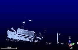
86 Experimental Results (I) Power Plant Dataset: Scan 0 Scan 6 Scan 5 Scan 4 Scan 1 Scan 2 Scan 3 Scanner Positions 86
 Part of the scan: only precise")
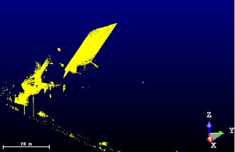
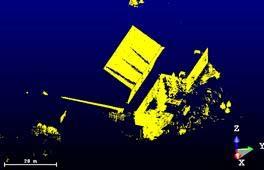
87 Experimental Results (I) Power Plant Dataset: Segmentation Segmentation Result (scan 5 ) Part of the scan: only precise features 87
")


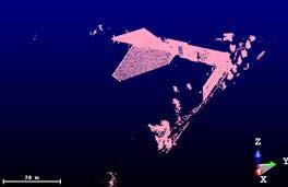
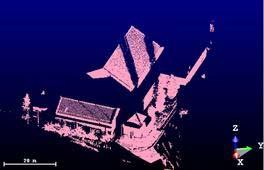
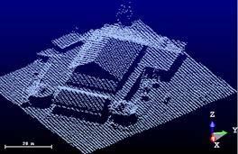
88 Experimental Results (I) Power Plant Dataset: Segmentation Top View 88 Side View Side View
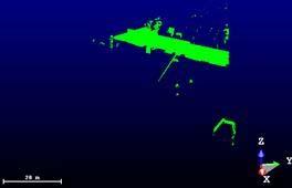
89 Experimental Results (I) Power Plant Dataset: Segmentation Long and precise fitting of lines: Scan ID Number of Linear Features Lines > 1m, Sigma <.1m 89
90 Experimental Results (I) Power Plant Dataset: Registration Scans ID RANSAC approach: all combinations # Combinations Candidate matches Solutions (1) Order among the solutions (2) Order among the conducted trials 90 Order of most probable solution (1) Order of most probable solution (2) 5-0 4,517,568 14, , ,726,068 26, , ,855,460 60, , ,517,568 13, ,949, , , ,544, , ,106 Combinations: total number of line pairs combinations in the scans Candidate matches: lines with similar angular and spatial separation values Solutions: number of times in which 3 lines aligned (7 lines for scans 5 and 6)
91 Experimental Results (I) Power Plant Dataset: Registration Scans ID Association approach: all combinations Combinations Candidate matches Solutions (1) Order among the solutions (2) Order among the conducted trials 91 Order of most probable solution (1) Order of most probable solution (2) 5-0 4,517,568 14, ,726,068 26, , ,855,460 60, , ,517,568 13, ,490,568 86, , ,544, , ,022 Combinations: total number of line pairs combinations in the scans Candidate matches: lines with similar angular and spatial separation values Solutions: number of times in which 3 lines aligned (7 lines for scans 5 and 6)
92 Experimental Results (I) Power Plant Dataset: Registration Association and Vs. RANSAC (probability) RANSAC Scan ID Number of Trials Number of Solutions 5-0 2, , , , , ,
93 Experimental Results (I) Power Plant Dataset: Registration Association and Vs. RANSAC (probability) Association Scan ID Number of Trials Number of Solutions 5-0 1, , , , , ,
94 Experimental Results (I) Power Plant Dataset: Registration Frequency-Based Approach Scans ID Candidate matches Peak Size (transformed center) , , , , , ,
95 Experimental Results (I) Power Plant Dataset: Registration Transformation Parameters using linear features Scans ID XT (M) YT (M) ZT (M) ωº φº κº RANSAC approach 95
 Power Plant")

96 Experimental Results (I) Power Plant Dataset: Registration Association and Vs. RANSAC 96
 using after ICPP linear procedure")
97 Experimental Results (I) Power Plant Dataset: Registration Transformation Parameters using linear features Registered Scans (5 and 0) using after ICPP linear procedure features 97
")

98 Experimental Results (I) Power Plant Dataset: Registration 98

99 Experimental Results Power Plant Dataset: Registration 99


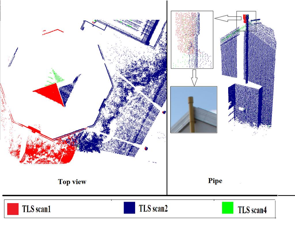
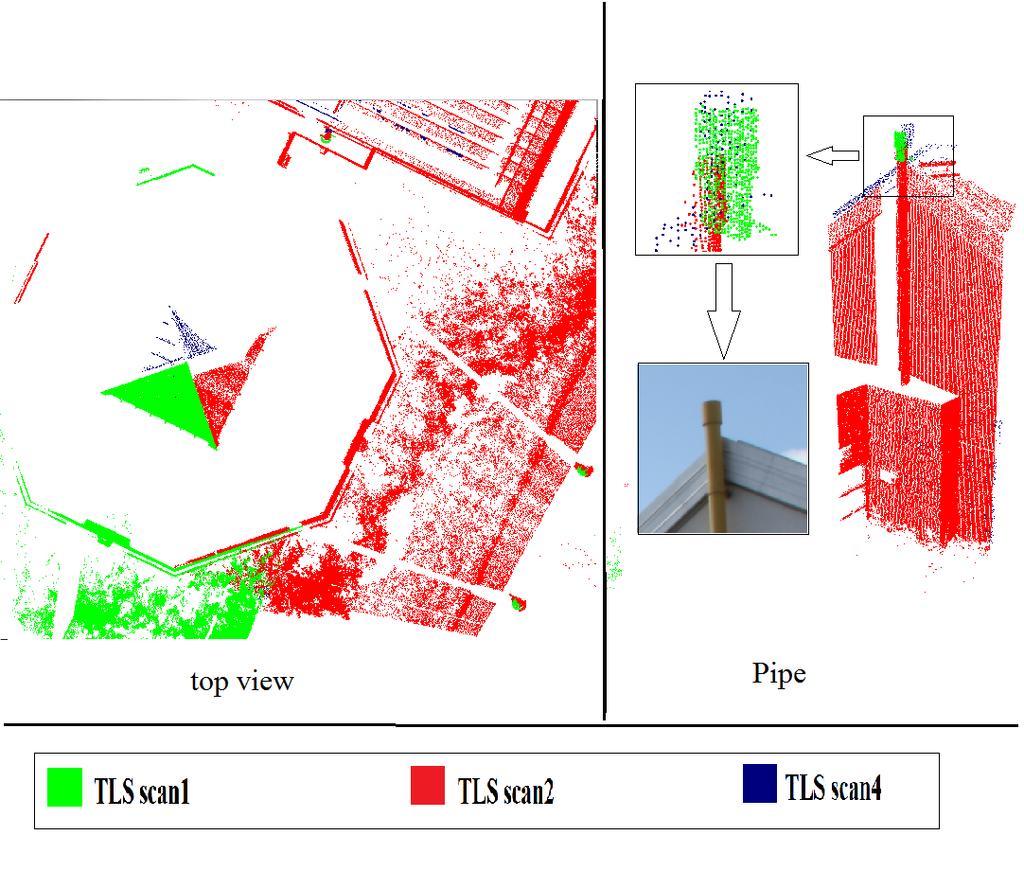
100 Experimental Results (II) A set of four laser scans of the Ronald McDonald House have been acquired using Leica HDS6100 laser scanner. Ronald McDonald House 100
101 Experimental Results (II) Scanner Positions Ronald McDonald House Scan4 Scan2 Scan3 Scan1 101
102 Experimental Results (II) Overlap area Scan 1 Scan 3 Example of the extracted lines from scans 1 and 3 102
103 Experimental Results (II) 103 Line ID a1 a2 a3 a4 a5 a6 a7 a8 a9 a11 a13 a14 a17 a19 a21 a22 a23 a24 a26 b b b b b b b b b b b b b b b b b b b b b b b b Example of an association matrix from scans 1 and 3
 Scans")

104 Experimental Results (II) Scans 11,2,3, 1 and and 2 34 registered together 104
")


105 Experimental Results (II) Top View of the registered scans Side view of the registered scans 105
106 Conclusions The proposed research outlined several approaches for the automatic registration of terrestrial laser scans using linear features. Parameter-domain and region growing approaches for the extraction of linear features from terrestrial laser scans are introduced. The synergistic integration of two different registration methodologies (i.e., linear features and ICPP) helps in overcoming the drawbacks of each method. The registration results for the electrical substation are satisfactory. 106
107 Current & Future Work Develop an automatic matching procedure that will be able to estimate the transformation parameters between multiple laser scans simultaneously Utilize non-positional point cloud characteristics such as intensity/rgb information for the automatic matching process Hypothesis generation using more than two lines at a time Recognition and modeling of objects of interest 107
108 Planar and Linear Feature-Based Registration of Terrestrial Laser Scans with Minimal Overlap Using Photogrammetric Data CASE STUDY 108


109 3D Data Derivation 3D data can be obtained through either photogrammetric or laser scanning systems. Direct Acquisition of 3D Point Cloud Camera source: Laser Scanner source: 109
110 Registration: Introduction Relationship between the TLS scans and a reference frame has to be estimated to align the scans relative to a single coordinate system: registration Problem. 110
111 Registration: Introduction The most commonly used method for registering 3D data is the Iterative Closes Point (ICP); Besl and McKay, Similar method to the ICP; Chen and Medioni 1992 These registration methods require large overlap area among the scans. In this research, the large overlap area requirement among the scans is reduced using photogrammetric data, which can be acquired in a relatively short time, as additional information. 111


112 Research Objectives The primary objective of this research is to avoid the large overlap area requirement among the TLS scans using photogrammetric data (planar & linear features). The second objective is to compare and analyze the results of the planar and linear feature-based registration approaches using quality control techniques. A quantitative quality control is proposed by calculating the point to plane normal distance between the registered surfaces. 112
113 Proposed Approach: Conceptual Basis Capture TLS data with minimal overlap Capture overlapping images of the object of interest Generate 3D features (planar or linear features) from the photogrammetric model, which is defined relative to an arbitrary reference frame: Photogrammetrically Reconstructed Data (PRD) Least-Squares Adjustment (LSA) for the registration of the TLS data using the PRD Derive the corresponding TLS features to those in the PRD The TLS data is aligned relative to the photogrammetric model, which is finally aligned to the global reference frame. This is done through a single step procedure. 113


114 Registration Paradigm Registration Primitives: Points, planar, and linear features are possible primitives. 114
115 Registration Paradigm Transformation Parameters: Rigid body transformation The photogrammetric model and TLS scans need to be rotated, scaled, and shifted until they fit at the global coordinate system. Similarity Measure: Mathematically describes the coincidence of conjugate primitives after applying the appropriate transformation parameters Matching Strategy: Utilizes primitives, similarity measure, and transformation parameters to automatically solve the registration problem 115

116 Features Extraction: Photogrammetric Data Planar Features Three or four non-collinear points are observed in multiple images and their object space coordinates are estimated through the bundle adjustment procedure. 116
.")
117 Features Extraction: Data Planar Features A segmentation procedure, which is established by Lari et al. (2011), is used to derive the planar features within the building in question. The TLS planar feature will be represented by randomly selected points (three or more noncollinear points). The number of points is equivalent to the number of points defining the corresponding planar feature in the PRD (no need for conjugate points). 117
118 Features Extraction: Photogrammetric Data : the vector connecting the perspective center to the beginning point along the line in object space; : the vector connecting the perspective center to the ending point along the line in object space; : the vector connecting the perspective center to the intermediate point along the corresponding image line. Linear Features The linear feature in the PRD will be represented by two points. Coplanarity Constraint (Habib et. al, 2004; Habib et. al, 2007, and Renaudin et. al, 2011)
.")

119 Features Extraction: Data Linear Features Two points, which define the linear features, are extracted automatically through the intersection of neighboring segmented planes (Al-Durgham, 2007; Lari et al, 2011). The TLS linear feature will be represented by two points. No need for conjugate points along the TLS and PRD linear features Source: Al-Durgham, MSc Thesis, 119
120 Transformation Parameters Similarity Measure Point-Based 3D Similarity Transformation / / / / PRD = Photogrammetrically Reconstructed Data / = scan or PRD : coordinates in the global reference frame /: the observation vector (model coordinates) : the translation vector between scan / i/prd and global coordinate system (reference scan) / : the scale factor between scan i /PRD and global coordinate system /: the rotation matrix relating scan i /PRD and global coordinate system; defined by the angles: Ω, Ф, and К 120
121 Transformation Parameters Similarity Measure Non-corresponding Points Along Conjugate Features Planar Features Linear Features 121

122 LSA Weight Modification / / / / =0 original weight matrix Planar Features Linear Features


123 Quality Control Procedure Quality Control Qualitative Quality Control Quantitative Quality Control Compared with the "Iterative Closest Projected Point ICPP(Al-Durgham, 2011) Point-to-plane normal distances between the registered PRD and TLS scans 123
 TLS scan1 TLS scan2 TLS scan3 TLS scan4 TLS scan1 TLS scan2 TLS scan3 TLS scan4 %1 %0 %0 %1 %0 %0 %0 %0 %19 %0 %0 %19 124")
124 Dataset Description 4 minimally overlapping TLS scans were collected using a Trimble GS200 scanner around the Rozsa Center (UofC). Rozsa Center ( TLS scan1 TLS scan2 TLS scan3 TLS scan4 TLS scan1 TLS scan2 TLS scan3 TLS scan4 %1 %0 %0 %1 %0 %0 %0 %0 %19 %0 %0 %19 124
125 Dataset Description 16 images of the Rozsa Center were collected for photogrammetric object reconstruction using a Canon EOS Rebel XS camera. Top view of overlap area and camera positions among the 16 images covering Rozsa Center 125

126 Results: Planar Feature-Based Registration 126
127 Results: Planar Feature-Based Registration XT (m) YT (m) ZT (m) Scale Ω ( o ) Ф ( o ) Κ ( o ) TLS scan TLS scan (±0.0287) (±0.0219) (±0.0805) (±0.1133) (±0.2092) (±0.0484) TLS scan (±0.0221) (±0.0293) (±0.0431) (±0.0624) (±0.0781) (±0.0441) TLS scan PRD (±0.0298) (±0.0184) (±0.0234) (±0.0163) (±0.0916) (±0.0143) (±0.0003) (±0.1273) (±0.2271) (±0.0769) (±0.0419) (±0.0447) (±0.2261) 127

128 Results: Planar Feature-Based Registration 128
 0.")
 0.051-0.09 0.019-0.033 0.016 Std_Dev (m) 0.070 0.043 0.013 0.036 0.")
129 Results: Planar Feature-Based Registration TLS scan1 vs. PRD TLS scan2 vs. PRD TLS scan3 vs. PRD TLS scan4 vs. PRD Plane ID Plane 1 Plane 2 Plane 3 Plane 4 Plane 5 Plane 8 Plane 9 Plane 12 Plane 13 Plane XZplanplanplanplanplane plane plane YZ- XZ- XY- XZ- Slope XZ- XY-plane YZ-plane Orientation Mean (m) Std_Dev (m) RMSE (m) Plane ID Plane 14 Plane 16 Plane 17 Plane 20 Plane 21 Plane YZplanplanplanplanplane XZ- YZ- XY- YZ- Orientation Mean (m) Std_Dev (m) RMSE (m) Plane ID Plane 22 Plane 23 Plane 24 Plane 26 Plane 27 Plane 28 Plane 29 Plane 30 Plane XZplanplanplane plane plane plane plane YZ- XZ- Slope YZ- Slope YZ- Orientation YZ-plane Mean (m) Std_Dev (m) RMSE (m) Plane ID Plane 22 Plane 23 Plane 24 Plane 26 Plane 35 Plane 36 Plane XZplanplanplane YZ- XZ- Slope XZ- YZ- Orientation plane plane plane Mean (m) Std_Dev (m) RMSE (m)

130 Results: Linear Feature-Based Registration 130

 (±0.1569) TLS scan3 69.639 92.565 1.284 0.681 0.")
 (±0.1071) TLS scan4-41.787 91.305-0.751-0.803 0.")
 (±0.1263) PRD 5.461 1.635 37.384 0.998 31.338-74.")
 (±0.1408) (±0.")
131 XT (m) YT (m) ZT (m) Scale Ω ( o ) Ф ( o ) Κ ( o ) TLS scan TLS scan (±0.0685) (±0.0341) (±0.1226) (±0.2571) (±0.5158) (±0.1569) TLS scan (±0.0661) (±0.0646) (±0.7231) (±0.4161) (±0.5422) (±0.1071) TLS scan (±0.0983) (±0.0724) (±0.3747) (±0.4175) (±0.2541) (±0.1263) PRD (±0.0722) (±0.0393) (±0.0336) (±0.0006) (±0.8272) (±0.1408) (±0.7643) Results: Linear Feature-Based Registration 131

132 Results: Linear Feature-Based Registration 132
 -0.030 0.")
 0.054 0.049 0.040 0.133 0.019 0.046 0.105 0.007 0.007 Plane ID Plane 14 Plane 16 Plane 17 Plane 20 Plane 21 Plane Orientation YZplane XZplane YZplane XYplane YZplane Mean (m) 0.035-0.")
133 Results: Linear Feature-Based Registration TLS scan1 vs. PRD TLS scan2 vs. PRD TLS scan3 vs. PRD TLS scan4 vs. PRD Plane ID Plane 1 Plane 2 Plane 3 Plane 4 Plane 5 Plane 8 Plane 9 Plane 12 Plane 13 Plane Orientation XZplane YZplane XZplane XYplane XZplane Slope plane XZplane XYplane YZplane Mean (m) Std_Dev (m) RMSE (m) Plane ID Plane 14 Plane 16 Plane 17 Plane 20 Plane 21 Plane Orientation YZplane XZplane YZplane XYplane YZplane Mean (m) Std_Dev (m) RMSE (m) Plane ID Plane 22 Plane 23 Plane 24 Plane 26 Plane 27 Plane 28 Plane 29 Plane 30 Plane Orientation XZplane YZplane XZplane Slope plane YZplane Slope plane YZplane YZplane Mean (m) Std_Dev (m) RMSE (m) Plane ID Plane 22 Plane 23 Plane 24 Plane 26 Plane 35 Plane 36 Plane Orientation XZplane YZplane XZplane Slope plane XZplane YZplane Mean (m) Std_Dev (m) RMSE (m)
134 Linear Feature-Based Registration Potential Problem: Occurs when the derived linear features from neighboring plane intersections might not correspond to physical linear features that could be identified in the imagery. 134

135 Linear Feature-Based Registration Potential Problem: 135
136 TLS scans TLS scan2 TLS scan3 TLS scan4 PRD Comparison with the ICPP Parameters the ICPP Planar based Linear based the ICPP vs. the ICPP vs. Linear vs. method registration registration planar based linear based planar based XT (m) YT (m) ZT (m) Scale Ω( o ) ф( o ) κ( o ) XT (m) YT (m) ZT (m) Scale Ω( o ) ф( o ) κ( o ) XT (m) YT (m) ZT (m) Scale Ω( o ) ф( o ) The ICPP is possible only after adding κ( o ) XT (m) more scans to increase the overlap YT (m) ZT (m) percentage among the scans. Scale Ω( o ) ф( o ) κ( o )
137 Conclusions & Recommendations Commonly used registration methods cannot align TLS scans with minimal overlap area. The proposed registration method depends on derived planar and linear features from a photogrammetric model to register TLS scans with minimal overlap. Qualitative and quantitative QC procedures proved the feasibility of the proposed approach. Planar feature-based registration is quite reliable. Linear feature-based registration will have problems when the TLS features are not visible in the image data. Current & future work: Automated feature extraction from imagery (Dense Matching Algorithms) Use airborne datasets for the registration of TLS data 137
138 References Al-Durgham, K., & Habib, A. (2014). Association-Matrix-Based Sample Consensus Approach for Automated Registration of Terrestrial Laser Scans Using Linear Features. Photogrammetric Engineering & Remote Sensing,80(11), Al-Durgham, K., Habib, A., & Mazaheri, M. (2014, March). Solution frequency-based procedure for automated registration of terrestrial laser scans using linear features. In Proceedings of the ASPRS 2014 Annual Conference, Louisville, Kentucky (pp ). Al-Durgham, M. M. (2007, September). Alternative methodologies for the quality control of lidar systems. In Masters Abstracts International (Vol. 46, No. 03). Al-Durgham, M., Detchev, I., & Habib, A. (2011). Analysis of two triangle-based multi-surface registration algorithms of irregular point clouds. ISPRS-International Archives of the Photogrammetry, Remote Sensing and Spatial Information Sciences, 3812, Besl, P. J., & McKay, N. D. (1992, April). Method for registration of 3-D shapes. In Robotics-DL tentative (pp ). International Society for Optics and Photonics. Canaz, S., & Habib, A. (2014). Photogrammetric features for the registration of terrestrial laser scans with minimum overlap. Journal of Geodesy and Geoinformation, 2(1). Chen, Y., & Medioni, G. (1991, April). Object modeling by registration of multiple range images. In Robotics and Automation, Proceedings., 1991 IEEE International Conference on (pp ). IEEE. Csanyi, N., & Toth, C. K. (2007). Improvement of lidar data accuracy using lidar-specific ground targets. Photogrammetric Engineering & Remote Sensing,73(4), Fischler, M. A., & Bolles, R. C. (1981). Random sample consensus: a paradigm for model fitting with applications to image analysis and automated cartography. Communications of the ACM, 24(6), Habib, A., Kersting, A. P., Bang, K. I., & Lee, D. (2010). Alternative methodologies for the internal quality control of parallel LiDAR strips.geoscience and Remote Sensing, IEEE Transactions on, 48(1), Habib, A. F., & Alruzouq, R. I. (2004). Line based modified iterated Hough transform for automatic registration of multi source imagery. The Photogrammetric Record, 19(105), Horn, B. K. (1987). Closed-form solution of absolute orientation using unit quaternions. JOSA A, 4(4), Jaw, J. J., & Chuang, T. Y. (2008). Registration of ground based LiDAR point clouds by means of 3D line features. Journal of the Chinese Institute of Engineers, 31(6), Lari, Z., & Habib, A. (2014). An adaptive approach for the segmentation and extraction of planar and linear/cylindrical features from laser scanning data.isprs Journal of Photogrammetry and Remote Sensing, 93, Renaudin, E., Habib, A., & Kersting, A. P. (2011). Featured-based Registration of terrestrial laser scans with minimum overlap using photogrammetric data.etri Journal, 33(4), Yao, J., Ruggeri, M. R., Taddei, P., & Sequeira, V. (2010). Automatic scan registration using 3D linear and planar features. 3D Research, 1(3),
RANSAC APPROACH FOR AUTOMATED REGISTRATION OF TERRESTRIAL LASER SCANS USING LINEAR FEATURES
 RANSAC APPROACH FOR AUTOMATED REGISTRATION OF TERRESTRIAL LASER SCANS USING LINEAR FEATURES K. AL-Durgham, A. Habib, E. Kwak Department of Geomatics Engineering, University of Calgary, Calgary, Alberta,
Association-Matrix-Based Sample Consensus Approach for Automated Registration of Terrestrial Laser Scans Using Linear Features
 Association-Matrix-Based Sample Consensus Approach for Automated Registration of Terrestrial Laser Scans Using Linear Features Kaleel Al-Durgham and Ayman Habib Abstract This paper presents an approach
SOLUTION FREQUENCY-BASED PROCEDURE FOR AUTOMATED REGISTRATION OF TERRESTRIAL LASER SCANS USING LINEAR FEATURES INTRODUCTION
 SOLUTION FREQUENCY-BASED PROCEDURE FOR AUTOMATED REGISTRATION OF TERRESTRIAL LASER SCANS USING LINEAR FEATURES ABSTRACT Kaleel Al-Durgham, Ayman Habib, Mehdi Mazaheri Department of Geomatics Engineering,
AN ADAPTIVE APPROACH FOR SEGMENTATION OF 3D LASER POINT CLOUD
 AN ADAPTIVE APPROACH FOR SEGMENTATION OF 3D LASER POINT CLOUD Z. Lari, A. F. Habib, E. Kwak Department of Geomatics Engineering, University of Calgary, Calgary, Alberta, Canada TN 1N4 - (zlari, ahabib,
INFO0948 Fitting and Shape Matching
 INFO0948 Fitting and Shape Matching Renaud Detry University of Liège, Belgium Updated March 31, 2015 1 / 33 These slides are based on the following book: D. Forsyth and J. Ponce. Computer vision: a modern
Intensity Augmented ICP for Registration of Laser Scanner Point Clouds
 Intensity Augmented ICP for Registration of Laser Scanner Point Clouds Bharat Lohani* and Sandeep Sashidharan *Department of Civil Engineering, IIT Kanpur Email: blohani@iitk.ac.in. Abstract While using
Model-based segmentation and recognition from range data
 Model-based segmentation and recognition from range data Jan Boehm Institute for Photogrammetry Universität Stuttgart Germany Keywords: range image, segmentation, object recognition, CAD ABSTRACT This
Algorithm research of 3D point cloud registration based on iterative closest point 1
 Acta Technica 62, No. 3B/2017, 189 196 c 2017 Institute of Thermomechanics CAS, v.v.i. Algorithm research of 3D point cloud registration based on iterative closest point 1 Qian Gao 2, Yujian Wang 2,3,
FAST REGISTRATION OF TERRESTRIAL LIDAR POINT CLOUD AND SEQUENCE IMAGES
 FAST REGISTRATION OF TERRESTRIAL LIDAR POINT CLOUD AND SEQUENCE IMAGES Jie Shao a, Wuming Zhang a, Yaqiao Zhu b, Aojie Shen a a State Key Laboratory of Remote Sensing Science, Institute of Remote Sensing
IGTF 2016 Fort Worth, TX, April 11-15, 2016 Submission 149
 IGTF 26 Fort Worth, TX, April -5, 26 2 3 4 5 6 7 8 9 2 3 4 5 6 7 8 9 2 2 Light weighted and Portable LiDAR, VLP-6 Registration Yushin Ahn (yahn@mtu.edu), Kyung In Huh (khuh@cpp.edu), Sudhagar Nagarajan
CE 59700: LASER SCANNING
 Digital Photogrammetry Research Group Lyles School of Civil Engineering Purdue University, USA Webpage: http://purdue.edu/ce/ Email: ahabib@purdue.edu CE 59700: LASER SCANNING 1 Contact Information Instructor:
AUTOMATIC GENERATION OF DIGITAL BUILDING MODELS FOR COMPLEX STRUCTURES FROM LIDAR DATA
 AUTOMATIC GENERATION OF DIGITAL BUILDING MODELS FOR COMPLEX STRUCTURES FROM LIDAR DATA Changjae Kim a, Ayman Habib a, *, Yu-Chuan Chang a a Geomatics Engineering, University of Calgary, Canada - habib@geomatics.ucalgary.ca,
DETECTION AND ROBUST ESTIMATION OF CYLINDER FEATURES IN POINT CLOUDS INTRODUCTION
 DETECTION AND ROBUST ESTIMATION OF CYLINDER FEATURES IN POINT CLOUDS Yun-Ting Su James Bethel Geomatics Engineering School of Civil Engineering Purdue University 550 Stadium Mall Drive, West Lafayette,
FULL AUTOMATIC REGISTRATION OF LASER SCANNER POINT CLOUDS
 FULL AUTOMATIC REGISTRATION OF LASER SCANNER POINT CLOUDS Devrim Akca Institute of Geodesy and Photogrammetry, ETH - Zurich, Switzerland http://www.photogrammetry.ethz.ch 1 The Goal: is automatic registration
REGISTRATION OF AIRBORNE LASER DATA TO SURFACES GENERATED BY PHOTOGRAMMETRIC MEANS. Y. Postolov, A. Krupnik, K. McIntosh
 REGISTRATION OF AIRBORNE LASER DATA TO SURFACES GENERATED BY PHOTOGRAMMETRIC MEANS Y. Postolov, A. Krupnik, K. McIntosh Department of Civil Engineering, Technion Israel Institute of Technology, Haifa,
Surface Registration. Gianpaolo Palma
 Surface Registration Gianpaolo Palma The problem 3D scanning generates multiple range images Each contain 3D points for different parts of the model in the local coordinates of the scanner Find a rigid
Reconstruction of complete 3D object model from multi-view range images.
 Header for SPIE use Reconstruction of complete 3D object model from multi-view range images. Yi-Ping Hung *, Chu-Song Chen, Ing-Bor Hsieh, Chiou-Shann Fuh Institute of Information Science, Academia Sinica,
FOOTPRINTS EXTRACTION
 Building Footprints Extraction of Dense Residential Areas from LiDAR data KyoHyouk Kim and Jie Shan Purdue University School of Civil Engineering 550 Stadium Mall Drive West Lafayette, IN 47907, USA {kim458,
EXTENDED GAUSSIAN IMAGES FOR THE REGISTRATION OF TERRESTRIAL SCAN DATA
 ISPRS WG III/3, III/4, V/3 Workshop "Laser scanning 2005", Enschede, the Netherlands, September 2-4, 2005 EXTENDED GAUSSIAN IMAGES FOR THE REGISTRATION OF TERRESTRIAL SCAN DATA Christoph Dold Institute
High Definition Modeling of Calw, Badstrasse and its Google Earth Integration
 Master Thesis Yuanting LI High Definition Modeling of Calw, Badstrasse and its Google Earth Integration Duration of the Thesis: 6 months Completion: July, 2014 Supervisors: Prof.Dr.-Ing.Dieter Fritsch
Model Fitting, RANSAC. Jana Kosecka
 Model Fitting, RANSAC Jana Kosecka Fitting: Overview If we know which points belong to the line, how do we find the optimal line parameters? Least squares What if there are outliers? Robust fitting, RANSAC
PLANE-BASED COARSE REGISTRATION OF 3D POINT CLOUDS WITH 4D MODELS
 PLANE-BASED COARSE REGISTRATION OF 3D POINT CLOUDS WITH 4D MODELS Frédéric Bosché School of the Built Environment, Heriot-Watt University, Edinburgh, Scotland bosche@vision.ee.ethz.ch ABSTRACT: The accurate
Structured light 3D reconstruction
 Structured light 3D reconstruction Reconstruction pipeline and industrial applications rodola@dsi.unive.it 11/05/2010 3D Reconstruction 3D reconstruction is the process of capturing the shape and appearance
Chapters 1 7: Overview
 Chapters 1 7: Overview Photogrammetric mapping: introduction, applications, and tools GNSS/INS-assisted photogrammetric and LiDAR mapping LiDAR mapping: principles, applications, mathematical model, and
Robust Range Image Registration using a Common Plane
 VRVis Technical Report 1 Robust Range Image Registration using a Common Plane Joachim Bauer bauer@icg.vrvis.at Konrad Karner karner@vrvis.at Andreas Klaus klaus@vrvis.at Roland Perko University of Technology
Stereo and Epipolar geometry
 Previously Image Primitives (feature points, lines, contours) Today: Stereo and Epipolar geometry How to match primitives between two (multiple) views) Goals: 3D reconstruction, recognition Jana Kosecka
AUTOMATIC ORIENTATION AND MERGING OF LASER SCANNER ACQUISITIONS THROUGH VOLUMETRIC TARGETS: PROCEDURE DESCRIPTION AND TEST RESULTS
 AUTOMATIC ORIENTATION AND MERGING OF LASER SCANNER ACQUISITIONS THROUGH VOLUMETRIC TARGETS: PROCEDURE DESCRIPTION AND TEST RESULTS G.Artese a, V.Achilli b, G.Salemi b, A.Trecroci a a Dept. of Land Planning,
Robotics Programming Laboratory
 Chair of Software Engineering Robotics Programming Laboratory Bertrand Meyer Jiwon Shin Lecture 8: Robot Perception Perception http://pascallin.ecs.soton.ac.uk/challenges/voc/databases.html#caltech car
A 3D Point Cloud Registration Algorithm based on Feature Points
 International Conference on Information Sciences, Machinery, Materials and Energy (ICISMME 2015) A 3D Point Cloud Registration Algorithm based on Feature Points Yi Ren 1, 2, a, Fucai Zhou 1, b 1 School
arxiv: v1 [cs.cv] 28 Sep 2018
![arxiv: v1 [cs.cv] 28 Sep 2018](/thumbs/93/113542646.jpg "arxiv: v1 [cs.cv] 28 Sep 2018") Camera Pose Estimation from Sequence of Calibrated Images arxiv:1809.11066v1 [cs.cv] 28 Sep 2018 Jacek Komorowski 1 and Przemyslaw Rokita 2 1 Maria Curie-Sklodowska University, Institute of Computer Science,
Camera Pose Estimation from Sequence of Calibrated Images arxiv:1809.11066v1 [cs.cv] 28 Sep 2018 Jacek Komorowski 1 and Przemyslaw Rokita 2 1 Maria Curie-Sklodowska University, Institute of Computer Science,
Homographies and RANSAC
 Homographies and RANSAC Computer vision 6.869 Bill Freeman and Antonio Torralba March 30, 2011 Homographies and RANSAC Homographies RANSAC Building panoramas Phototourism 2 Depth-based ambiguity of position
arxiv: v1 [cs.cv] 28 Sep 2018
![arxiv: v1 [cs.cv] 28 Sep 2018](/thumbs/91/106305353.jpg "arxiv: v1 [cs.cv] 28 Sep 2018") Extrinsic camera calibration method and its performance evaluation Jacek Komorowski 1 and Przemyslaw Rokita 2 arxiv:1809.11073v1 [cs.cv] 28 Sep 2018 1 Maria Curie Sklodowska University Lublin, Poland jacek.komorowski@gmail.com
Extrinsic camera calibration method and its performance evaluation Jacek Komorowski 1 and Przemyslaw Rokita 2 arxiv:1809.11073v1 [cs.cv] 28 Sep 2018 1 Maria Curie Sklodowska University Lublin, Poland jacek.komorowski@gmail.com
Estimation of Camera Pose with Respect to Terrestrial LiDAR Data
 Estimation of Camera Pose with Respect to Terrestrial LiDAR Data Wei Guan Suya You Guan Pang Computer Science Department University of Southern California, Los Angeles, USA Abstract In this paper, we present
Structured Light II. Thanks to Ronen Gvili, Szymon Rusinkiewicz and Maks Ovsjanikov
 Structured Light II Johannes Köhler Johannes.koehler@dfki.de Thanks to Ronen Gvili, Szymon Rusinkiewicz and Maks Ovsjanikov Introduction Previous lecture: Structured Light I Active Scanning Camera/emitter
SEMANTIC FEATURE BASED REGISTRATION OF TERRESTRIAL POINT CLOUDS
 SEMANTIC FEATURE BASED REGISTRATION OF TERRESTRIAL POINT CLOUDS A. Thapa*, S. Pu, M. Gerke International Institute for Geo-Information Science and Earth Observation (ITC), Hengelosestraat 99, P.O.Box 6,
Fitting. Fitting. Slides S. Lazebnik Harris Corners Pkwy, Charlotte, NC
 Fitting We ve learned how to detect edges, corners, blobs. Now what? We would like to form a higher-level, more compact representation of the features in the image by grouping multiple features according
Reconstruction of Polygonal Faces from Large-Scale Point-Clouds of Engineering Plants
 1 Reconstruction of Polygonal Faces from Large-Scale Point-Clouds of Engineering Plants Hiroshi Masuda 1, Takeru Niwa 2, Ichiro Tanaka 3 and Ryo Matsuoka 4 1 The University of Electro-Communications, h.masuda@euc.ac.jp
Prof. Jose L. Flores, MS, PS Dept. of Civil Engineering & Surveying
 Prof. Jose L. Flores, MS, PS Dept. of Civil Engineering & Surveying Problem One of the challenges for any Geographic Information System (GIS) application is to keep the spatial data up to date and accurate.
A NEW AUTOMATIC SYSTEM CALIBRATION OF MULTI-CAMERAS AND LIDAR SENSORS
 A NEW AUTOMATIC SYSTEM CALIBRATION OF MULTI-CAMERAS AND LIDAR SENSORS M. Hassanein a, *, A. Moussa a,b, N. El-Sheimy a a Department of Geomatics Engineering, University of Calgary, Calgary, Alberta, Canada
A COMPETITION BASED ROOF DETECTION ALGORITHM FROM AIRBORNE LIDAR DATA
 A COMPETITION BASED ROOF DETECTION ALGORITHM FROM AIRBORNE LIDAR DATA HUANG Xianfeng State Key Laboratory of Informaiton Engineering in Surveying, Mapping and Remote Sensing (Wuhan University), 129 Luoyu
3D Computer Vision. Structured Light II. Prof. Didier Stricker. Kaiserlautern University.
 3D Computer Vision Structured Light II Prof. Didier Stricker Kaiserlautern University http://ags.cs.uni-kl.de/ DFKI Deutsches Forschungszentrum für Künstliche Intelligenz http://av.dfki.de 1 Introduction
EVALUATION OF SEQUENTIAL IMAGES FOR PHOTOGRAMMETRICALLY POINT DETERMINATION
 Archives of Photogrammetry, Cartography and Remote Sensing, Vol. 22, 2011, pp. 285-296 ISSN 2083-2214 EVALUATION OF SEQUENTIAL IMAGES FOR PHOTOGRAMMETRICALLY POINT DETERMINATION Michał Kowalczyk 1 1 Department
A DATA DRIVEN METHOD FOR FLAT ROOF BUILDING RECONSTRUCTION FROM LiDAR POINT CLOUDS
 A DATA DRIVEN METHOD FOR FLAT ROOF BUILDING RECONSTRUCTION FROM LiDAR POINT CLOUDS A. Mahphood, H. Arefi *, School of Surveying and Geospatial Engineering, College of Engineering, University of Tehran,
Least Squares 3D surface matching
 Least Squares 3D surface matching Devrim Akca Institute of Geodesy and Photogrammetry Swiss Federal Institute of Technology Zurich www.photogrammetry.ethz.ch 1 The Objective: Co-registration of overlapping
Correspondence. CS 468 Geometry Processing Algorithms. Maks Ovsjanikov
 Shape Matching & Correspondence CS 468 Geometry Processing Algorithms Maks Ovsjanikov Wednesday, October 27 th 2010 Overall Goal Given two shapes, find correspondences between them. Overall Goal Given
Manhattan-World Assumption for As-built Modeling Industrial Plant
 Manhattan-World Assumption for As-built Modeling Industrial Plant Tomohiro Mizoguchi 1, Tomokazu Kuma 2, Yoshikazu Kobayashi 3 and Kenji Shirai 4 Department of Computer Science, College of Engineering,
City-Modeling. Detecting and Reconstructing Buildings from Aerial Images and LIDAR Data
 City-Modeling Detecting and Reconstructing Buildings from Aerial Images and LIDAR Data Department of Photogrammetrie Institute for Geodesy and Geoinformation Bonn 300000 inhabitants At river Rhine University
Chapters 1 7: Overview
 Chapters 1 7: Overview Chapter 1: Introduction Chapters 2 4: Data acquisition Chapters 5 7: Data manipulation Chapter 5: Vertical imagery Chapter 6: Image coordinate measurements and refinements Chapter
Feature Based Registration - Image Alignment
 Feature Based Registration - Image Alignment Image Registration Image registration is the process of estimating an optimal transformation between two or more images. Many slides from Alexei Efros http://graphics.cs.cmu.edu/courses/15-463/2007_fall/463.html
AUTOMATED COARSE REGISTRATION OF POINT CLOUDS IN 3D URBAN SCENES USING VOXEL BASED PLANE CONSTRAINT
 AUTOMATED COARSE REGISTRATION OF POINT CLOUDS IN 3D URBAN SCENES USING VOXEL BASED PLANE CONSTRAINT Y. Xu a,, R. Boerner a, W. Yao a,b, L. Hoegner a, U. Stilla a a Photogrammetry and Remote Sensing, Technische
Advanced point cloud processing
 Advanced point cloud processing George Vosselman ITC Enschede, the Netherlands INTERNATIONAL INSTITUTE FOR GEO-INFORMATION SCIENCE AND EARTH OBSERVATION Laser scanning platforms Airborne systems mounted
Mosaics. Today s Readings
 Mosaics VR Seattle: http://www.vrseattle.com/ Full screen panoramas (cubic): http://www.panoramas.dk/ Mars: http://www.panoramas.dk/fullscreen3/f2_mars97.html Today s Readings Szeliski and Shum paper (sections
GENERATING BUILDING OUTLINES FROM TERRESTRIAL LASER SCANNING
 GENERATING BUILDING OUTLINES FROM TERRESTRIAL LASER SCANNING Shi Pu International Institute for Geo-information Science and Earth Observation (ITC), Hengelosestraat 99, P.O. Box 6, 7500 AA Enschede, The
Index. 3D reconstruction, point algorithm, point algorithm, point algorithm, point algorithm, 263
 Index 3D reconstruction, 125 5+1-point algorithm, 284 5-point algorithm, 270 7-point algorithm, 265 8-point algorithm, 263 affine point, 45 affine transformation, 57 affine transformation group, 57 affine
Extraction of façades with window information from oblique view airborne laser scanning point clouds
 Extraction of façades with window information from oblique view airborne laser scanning point clouds Sebastian Tuttas, Uwe Stilla Photogrammetry and Remote Sensing, Technische Universität München, 80290
Perception IV: Place Recognition, Line Extraction
 Perception IV: Place Recognition, Line Extraction Davide Scaramuzza University of Zurich Margarita Chli, Paul Furgale, Marco Hutter, Roland Siegwart 1 Outline of Today s lecture Place recognition using
Flexible Calibration of a Portable Structured Light System through Surface Plane
 Vol. 34, No. 11 ACTA AUTOMATICA SINICA November, 2008 Flexible Calibration of a Portable Structured Light System through Surface Plane GAO Wei 1 WANG Liang 1 HU Zhan-Yi 1 Abstract For a portable structured
Semi-Automatic Approach for Building Reconstruction Using SPLIT-MERGE-SHAPE Method
 Semi-Automatic Approach for Building Reconstruction Using SPLIT-MERGE-SHAPE Method Jiann-Yeou RAU, Liang-Chien CHEN Tel: 886-3-4227151 Ext. 7651,7627,7622 Fax: 886-3-4255535 {jyrau, lcchen} @csrsr.ncu.edu.tw
Point Cloud Processing
 Point Cloud Processing Has anyone seen the toothpaste? Given a point cloud: how do you detect and localize objects? how do you map terrain? What is a point cloud? Point cloud: a set of points in 3-D space
Uncertainties: Representation and Propagation & Line Extraction from Range data
 41 Uncertainties: Representation and Propagation & Line Extraction from Range data 42 Uncertainty Representation Section 4.1.3 of the book Sensing in the real world is always uncertain How can uncertainty
HEURISTIC FILTERING AND 3D FEATURE EXTRACTION FROM LIDAR DATA
 HEURISTIC FILTERING AND 3D FEATURE EXTRACTION FROM LIDAR DATA Abdullatif Alharthy, James Bethel School of Civil Engineering, Purdue University, 1284 Civil Engineering Building, West Lafayette, IN 47907
3D Environment Reconstruction
 3D Environment Reconstruction Using Modified Color ICP Algorithm by Fusion of a Camera and a 3D Laser Range Finder The 2009 IEEE/RSJ International Conference on Intelligent Robots and Systems October 11-15,
SIFT: SCALE INVARIANT FEATURE TRANSFORM SURF: SPEEDED UP ROBUST FEATURES BASHAR ALSADIK EOS DEPT. TOPMAP M13 3D GEOINFORMATION FROM IMAGES 2014
 SIFT: SCALE INVARIANT FEATURE TRANSFORM SURF: SPEEDED UP ROBUST FEATURES BASHAR ALSADIK EOS DEPT. TOPMAP M13 3D GEOINFORMATION FROM IMAGES 2014 SIFT SIFT: Scale Invariant Feature Transform; transform image
POINT CLOUD REGISTRATION: CURRENT STATE OF THE SCIENCE. Matthew P. Tait
 POINT CLOUD REGISTRATION: CURRENT STATE OF THE SCIENCE Matthew P. Tait Content 1. Quality control: Analyzing the true errors in Terrestrial Laser Scanning (TLS) 2. The prospects for automatic cloud registration
Interactive Collision Detection for Engineering Plants based on Large-Scale Point-Clouds
 1 Interactive Collision Detection for Engineering Plants based on Large-Scale Point-Clouds Takeru Niwa 1 and Hiroshi Masuda 2 1 The University of Electro-Communications, takeru.niwa@uec.ac.jp 2 The University
BUILDING DETECTION AND STRUCTURE LINE EXTRACTION FROM AIRBORNE LIDAR DATA
 BUILDING DETECTION AND STRUCTURE LINE EXTRACTION FROM AIRBORNE LIDAR DATA C. K. Wang a,, P.H. Hsu a, * a Dept. of Geomatics, National Cheng Kung University, No.1, University Road, Tainan 701, Taiwan. China-
Automatic Image Alignment (feature-based)
") Automatic Image Alignment (feature-based) Mike Nese with a lot of slides stolen from Steve Seitz and Rick Szeliski 15-463: Computational Photography Alexei Efros, CMU, Fall 2006 Today s lecture Feature
Automatic Image Alignment (feature-based) Mike Nese with a lot of slides stolen from Steve Seitz and Rick Szeliski 15-463: Computational Photography Alexei Efros, CMU, Fall 2006 Today s lecture Feature
Feature Detectors and Descriptors: Corners, Lines, etc.
 Feature Detectors and Descriptors: Corners, Lines, etc. Edges vs. Corners Edges = maxima in intensity gradient Edges vs. Corners Corners = lots of variation in direction of gradient in a small neighborhood
Automatic registration of terrestrial laser scans for geological deformation monitoring
 Automatic registration of terrestrial laser scans for geological deformation monitoring Daniel Wujanz 1, Michael Avian 2, Daniel Krueger 1, Frank Neitzel 1 1 Chair of Geodesy and Adjustment Theory, Technische
LIDAR Data for Photogrammetric Georeferencing
 LIDAR Data for Photogrammetric Georeferencing Ayman HABIB, Mwafag GHANMA and Eui-Myoung KIM, Canada Key words: laser scanning, photogrammetry, triangulation, linear-features, absolute orientation, registration.
[Youn *, 5(11): November 2018] ISSN DOI /zenodo Impact Factor
![[Youn *, 5(11): November 2018] ISSN DOI /zenodo Impact Factor](/thumbs/91/105079225.jpg "[Youn *, 5(11): November 2018] ISSN DOI /zenodo Impact Factor") GLOBAL JOURNAL OF ENGINEERING SCIENCE AND RESEARCHES AUTOMATIC EXTRACTING DEM FROM DSM WITH CONSECUTIVE MORPHOLOGICAL FILTERING Junhee Youn *1 & Tae-Hoon Kim 2 *1,2 Korea Institute of Civil Engineering
GLOBAL JOURNAL OF ENGINEERING SCIENCE AND RESEARCHES AUTOMATIC EXTRACTING DEM FROM DSM WITH CONSECUTIVE MORPHOLOGICAL FILTERING Junhee Youn *1 & Tae-Hoon Kim 2 *1,2 Korea Institute of Civil Engineering
CSE 252B: Computer Vision II
 CSE 252B: Computer Vision II Lecturer: Serge Belongie Scribes: Jeremy Pollock and Neil Alldrin LECTURE 14 Robust Feature Matching 14.1. Introduction Last lecture we learned how to find interest points
LIDAR SYSTEM SELF-CALIBRATION USING PLANAR PATCHES FROM PHOTOGRAMMETRIC DATA
 LIDAR SSTEM SELF-CALIBRATION USING PLANAR PATCHES FROM PHOTOGRAMMETRIC DATA Ayman F. Habib a, *, Ki In Bang a, Sung-Woong Shin b, Edson Mitishita c a Department of Geomatics Engineering, University of
TERRESTRIAL LASER SCANNER TECHNIC AS A METHOD FOR IDENTIFICATION AREAS OF SLOPS
 77 TERRESTRIAL LASER SCANNER TECHNIC AS A METHOD FOR IDENTIFICATION AREAS OF SLOPS Bartłomiej Ćmielewski, Bernard Kontny Institute of Geodesy and Geoinformatics, Wroclaw University of Environmental and
LOAM: LiDAR Odometry and Mapping in Real Time
 LOAM: LiDAR Odometry and Mapping in Real Time Aayush Dwivedi (14006), Akshay Sharma (14062), Mandeep Singh (14363) Indian Institute of Technology Kanpur 1 Abstract This project deals with online simultaneous
LATEST TRENDS on APPLIED MATHEMATICS, SIMULATION, MODELLING
 3D surface reconstruction of objects by using stereoscopic viewing Baki Koyuncu, Kurtuluş Küllü bkoyuncu@ankara.edu.tr kkullu@eng.ankara.edu.tr Computer Engineering Department, Ankara University, Ankara,
5.2 Surface Registration
 Spring 2018 CSCI 621: Digital Geometry Processing 5.2 Surface Registration Hao Li http://cs621.hao-li.com 1 Acknowledgement Images and Slides are courtesy of Prof. Szymon Rusinkiewicz, Princeton University
Icl: Iterative closest line
 Icl: Iterative closest line A novel point cloud registration algorithm based on linear features Majd Alshawa * Abstract. The problem of matching 3D TLS point clouds is a necessary stage which precedes
BUILDING ROOF RECONSTRUCTION BY FUSING LASER RANGE DATA AND AERIAL IMAGES
 BUILDING ROOF RECONSTRUCTION BY FUSING LASER RANGE DATA AND AERIAL IMAGES J.J. Jaw *,C.C. Cheng Department of Civil Engineering, National Taiwan University, 1, Roosevelt Rd., Sec. 4, Taipei 10617, Taiwan,
CLASSIFICATION FOR ROADSIDE OBJECTS BASED ON SIMULATED LASER SCANNING
 CLASSIFICATION FOR ROADSIDE OBJECTS BASED ON SIMULATED LASER SCANNING Kenta Fukano 1, and Hiroshi Masuda 2 1) Graduate student, Department of Intelligence Mechanical Engineering, The University of Electro-Communications,
Camera Pose Measurement from 2D-3D Correspondences of Three Z Shaped Lines
 International Journal of Intelligent Engineering & Systems http://www.inass.org/ Camera Pose Measurement from 2D-3D Correspondences of Three Z Shaped Lines Chang Liu 1,2,3,4, Feng Zhu 1,4, Jinjun Ou 1,4,
Today s lecture. Image Alignment and Stitching. Readings. Motion models
 Today s lecture Image Alignment and Stitching Computer Vision CSE576, Spring 2005 Richard Szeliski Image alignment and stitching motion models cylindrical and spherical warping point-based alignment global
BUILDING MODEL RECONSTRUCTION FROM DATA INTEGRATION INTRODUCTION
 BUILDING MODEL RECONSTRUCTION FROM DATA INTEGRATION Ruijin Ma Department Of Civil Engineering Technology SUNY-Alfred Alfred, NY 14802 mar@alfredstate.edu ABSTRACT Building model reconstruction has been
Aalborg Universitet. Published in: Accuracy Publication date: Document Version Early version, also known as pre-print
 Aalborg Universitet A method for checking the planimetric accuracy of Digital Elevation Models derived by Airborne Laser Scanning Høhle, Joachim; Øster Pedersen, Christian Published in: Accuracy 2010 Publication
Object Reconstruction
 B. Scholz Object Reconstruction 1 / 39 MIN-Fakultät Fachbereich Informatik Object Reconstruction Benjamin Scholz Universität Hamburg Fakultät für Mathematik, Informatik und Naturwissenschaften Fachbereich
Structure from Motion. Prof. Marco Marcon
 Structure from Motion Prof. Marco Marcon Summing-up 2 Stereo is the most powerful clue for determining the structure of a scene Another important clue is the relative motion between the scene and (mono)
Chapter 4. Clustering Core Atoms by Location
 Chapter 4. Clustering Core Atoms by Location In this chapter, a process for sampling core atoms in space is developed, so that the analytic techniques in section 3C can be applied to local collections
A SYSTEM OF THE SHADOW DETECTION AND SHADOW REMOVAL FOR HIGH RESOLUTION CITY AERIAL PHOTO
 A SYSTEM OF THE SHADOW DETECTION AND SHADOW REMOVAL FOR HIGH RESOLUTION CITY AERIAL PHOTO Yan Li a, Tadashi Sasagawa b, Peng Gong a,c a International Institute for Earth System Science, Nanjing University,
RANSAC and some HOUGH transform
 RANSAC and some HOUGH transform Thank you for the slides. They come mostly from the following source Dan Huttenlocher Cornell U Matching and Fitting Recognition and matching are closely related to fitting
A Multi-Resolution ICP with Heuristic Closest Point Search for Fast and Robust 3D Registration of Range Images
 A Multi-Resolution ICP with Heuristic Closest Point Search for Fast and Robust 3D Registration of Range Images Timothée Jost and Heinz Hügli Institute of Microtechnology, University of Neuchâtel, Breguet
Index. 3D reconstruction, point algorithm, point algorithm, point algorithm, point algorithm, 253
 Index 3D reconstruction, 123 5+1-point algorithm, 274 5-point algorithm, 260 7-point algorithm, 255 8-point algorithm, 253 affine point, 43 affine transformation, 55 affine transformation group, 55 affine
Instance-level recognition part 2
 Visual Recognition and Machine Learning Summer School Paris 2011 Instance-level recognition part 2 Josef Sivic http://www.di.ens.fr/~josef INRIA, WILLOW, ENS/INRIA/CNRS UMR 8548 Laboratoire d Informatique,
Scan Matching. Pieter Abbeel UC Berkeley EECS. Many slides adapted from Thrun, Burgard and Fox, Probabilistic Robotics
 Scan Matching Pieter Abbeel UC Berkeley EECS Many slides adapted from Thrun, Burgard and Fox, Probabilistic Robotics Scan Matching Overview Problem statement: Given a scan and a map, or a scan and a scan,
Robot Mapping. SLAM Front-Ends. Cyrill Stachniss. Partial image courtesy: Edwin Olson 1
 Robot Mapping SLAM Front-Ends Cyrill Stachniss Partial image courtesy: Edwin Olson 1 Graph-Based SLAM Constraints connect the nodes through odometry and observations Robot pose Constraint 2 Graph-Based
3D Models and Matching
 3D Models and Matching representations for 3D object models particular matching techniques alignment-based systems appearance-based systems GC model of a screwdriver 1 3D Models Many different representations
Shape Modeling of A String And Recognition Using Distance Sensor
 Proceedings of the 24th IEEE International Symposium on Robot and Human Interactive Communication Kobe, Japan, Aug 31 - Sept 4, 2015 Shape Modeling of A String And Recognition Using Distance Sensor Keisuke
AUTOMATIC EXTRACTION OF BUILDING FEATURES FROM TERRESTRIAL LASER SCANNING
 AUTOMATIC EXTRACTION OF BUILDING FEATURES FROM TERRESTRIAL LASER SCANNING Shi Pu and George Vosselman International Institute for Geo-information Science and Earth Observation (ITC) spu@itc.nl, vosselman@itc.nl
Automatic Image Alignment
 Automatic Image Alignment with a lot of slides stolen from Steve Seitz and Rick Szeliski Mike Nese CS194: Image Manipulation & Computational Photography Alexei Efros, UC Berkeley, Fall 2018 Live Homography
MULTIPLE-SENSOR INTEGRATION FOR EFFICIENT REVERSE ENGINEERING OF GEOMETRY
 Proceedings of the 11 th International Conference on Manufacturing Research (ICMR2013) MULTIPLE-SENSOR INTEGRATION FOR EFFICIENT REVERSE ENGINEERING OF GEOMETRY Feng Li, Andrew Longstaff, Simon Fletcher,
Surgery Simulation and Planning
 Surgery Simulation and Planning S. H. Martin Roth Dr. Rolf M. Koch Daniel Bielser Prof. Dr. Markus Gross Facial surgery project in collaboration with Prof. Dr. Dr. H. Sailer, University Hospital Zurich,